

Page 1
Motors | Autom ation | Energy | Transmi ssion & Distribu tion | Coatings
Digital I/O Expansion Module
Módulo de Expansión de I/O Digitales
Módulo de Expansão de I/O Digitais
CFW300-IODR
Installation, Configuration and Operation Guide
Guía de Instalación, Configuración y Operación
Guia de Instalação, Configuração e Operação
WEG Drives & Con trols - Automação LTDA.
Jaraguá do Sul - S C - Brazil
Phone 55 (47) 3276-4000 - Fa x 55 (47) 3276-4020
São Paulo - SP - Bra zil
Phone 55 (11) 5053-2300 - Fax 55 (11) 5052-4212
automacao@weg.net
www.weg.net
1 INFORMAÇÕES DE SEGURANÇA
1.1 AVISOS DE SEG URANÇA
NOTA !
Somente utili zar o módulo d e expansão de I /O digitais (C FW300-I ODR)
nos inversores WEG série CFW300.
Recomenda-se a leitura do manual do usuário do CFW300 antes
de instala r ou operar esse ac essório.
O conteúdo deste guia fornece informações importantes para o correto
entendimento e bom funcionamento deste módulo.
1.2 RECOMENDAÇÕES PRELIMINARES
ATENÇÃO!
Sempre desco necte a alim entação ge ral antes de c onectar ou
desconectar os acessórios do inversor de frequência CFW300.
Aguarde pelo me nos 10 minutos pa ra garanti r a desenerg ização
completa do inversor.
2 INFORMAÇÕES GERAIS
Este guia orienta na instalação, configuração e operação do módulo de expansão
de I/O digita is (CFW300-IO DR).
3 CONTEÚD O DA EMBAL AGEM
Ao receber o p roduto, verifica r se a embalagem co ntém:
Acessório em embalagem anti-estática.
Guia de instalação, configuração e operação.
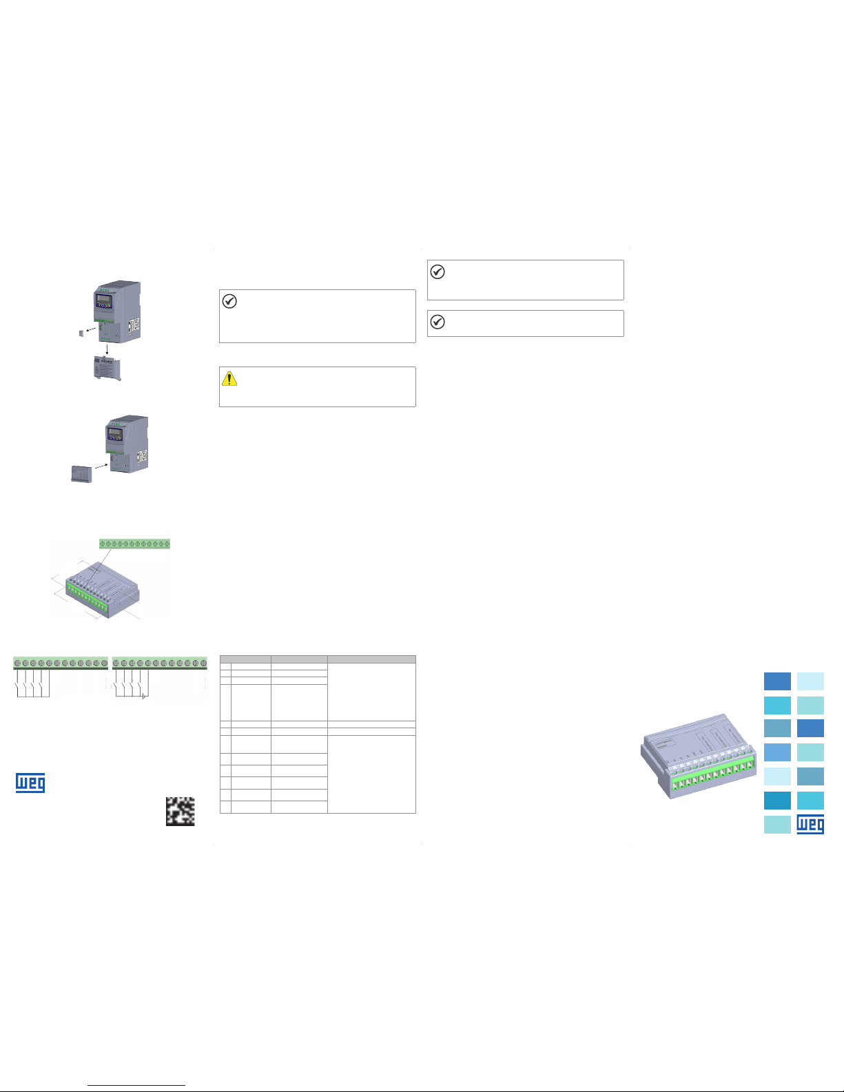
4 INSTALAÇÃO D O ACESSÓRIO
O CFW300 -IODR é faci lmente cone ctado ao inve rsor de freq uência CF W300
utilizando o conceito “plug-and-play”. Os procedimentos abaixo devem ser seguid os
para a correta instalação e colocação em funcionamento:
1. Com o invers or desenergiza do, retire a tampa de ac essórios de expa nsão de
IO’s e a tampa de prote ção da conexão dos ac essórios de expan são de IO’s
(XC4) do inver sor (Figura A1).
2. Encaixe o ac essório a ser ins talado conform e indicado na Figura A1.
3. E nergize o inversor.
5 CONFIGU RAÇÕES
As conexões d o acessór io CFW300 -IODR deve m ser feitas no c onector de
expansão d e I/O conform e Tabe la 1. Os pinos do conector do acessório são
apresentados na Figura A2. A Figura A3 apresenta exemplo s de ligação da s
entradas digitais, nas configurações NPN e PNP.
Tabela 1: Sinais do conector de exp ansão de I/O
Conector Descrição Especificações
13 DI5 Entrada digital 5 4 e ntradas digi tais config uráveis (NPN
ou PNP) e isolad as
Funções programáveis
At ivo alto (PNP): níve l baixo máxi mo
de 10 Vcc. Nível alto mín imo de 20 Vcc
At ivo baixo (NPN): níve l baixo máxim o
de 3 Vcc. Nível alto m ínimo de 10 Vcc
Tens ão de entrada máxi ma: 30 Vcc
C orrente de entrada t ípica: 11 mA
C orrente de entrada m áxima: 20 mA
14 DI6 Entrada digital 6
15 DI7 Entrada digital 7
16 DI8 Entrada digital 8
17 GND Referênci a 0 V N ão interligado co m o PE
18 GND Referência 0 V Não inte rligado com o PE
19 DO2 - RL - C Saída digital 2
(Ponto comum do relé 2)
3 relés com contato NA (Normalmente
aberto)
Tens ão máxima: 250 Vca
C orrente máx ima: 5 A (Carga res istiva)
C orrente mínima: >100 mA
Funções programáveis
20 DO2 - RL - NO Saída digital 2
(Ponto NA do relé 2)
21 DO3 - RL - C Saída digital 3
(Ponto comum do relé 3)
22 DO3 - RL - NO Saída digital 3
(Ponto NA do relé 3)
23 DO4 - RL - C Saída digital 4
(Ponto comum do relé 4)
24 DO4 - RL - NO Saída digital 4
(Ponto NA do relé 4)
NOTA !
Por padrão, as e ntradas dig itais do inve rsor CFW3 00 e do acess ório
CFW300 -IODR estão c onfigura das como ativo b aixo (NPN). Para a lterar,
verifiq ue a utilizaç ão do parâme tro P271 no manual d e programaç ão
do CFW300 .
NOTA !
A versão de so ftware do ac essório CF W300-IOD R pode ser vis ualizada
no parâmet ro P024 do inversor CFW3 00.
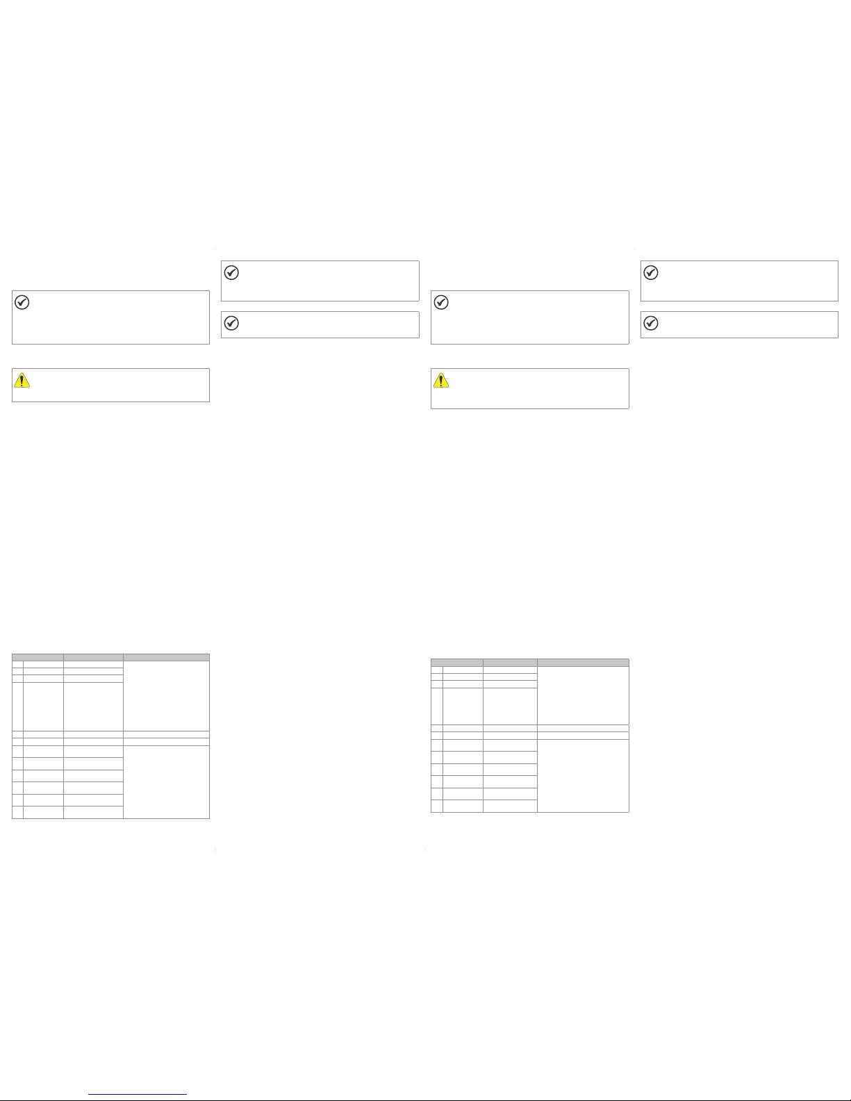
PortuguêsAPPENDI X A - FIGURES
ANEXO A - FIG URAS
(a) Removal of th e accessory a nd connecti on protection c overs (XC4) from th e IO expansion
(a) Remoción d e las tapas de ac cesorios y de pr otección de la co nexión (XC4) de la
expansió n de IO´s
(a) Remoção da s tampas de ace ssórios e de pro teção da conexã o (XC4) da expans ão de IO's
(b) Accessory connection
(b) Conexión del accesorio
(b) Conexão de acessório
Figure A1: (a) to (b) Installati on of accessory
Figura A1: (a) a (b) Instalació n del accesorio
Figura A1: (a) a (b) Instalação d e acessório
20.6 [0.81]
64 [2.52]
46.8 [1.84]
I/O expansion connector
Conector de expansión de I/O
Conector de ex pansão de I/O
Figure A2: CFW300-IODR di mentions in mm [in]
Figura A2: Dimensiones de l CFW300-IODR e n mm [in]
Figura A2: Dimensões do CF W300-IODR em mm [in]
13 14 15
DI5
DI6
DI7
DI8
GND
GND
DO2 - RL - C
DO3 - RL - C
DO4 - RL - C
DO2 - RL - NO
DO3 - RL - NO
DO4 - RL - NO
16 17 18 19 20 21 22 23 24
External supply
Fuente externa
Fonte externa
13 14 15
DI5
DI6
DI7
DI8
GND
GND
DO2 - RL - C
DO3 - RL - C
DO4 - RL - C
DO2 - RL - NO
DO3 - RL - NO
DO4 - RL - NO
16 17
24 V
18 19 20 21 22 23 24
(a) Digital I nputs as acti ve low (NPN)
(a) Entradas D igitales co mo activo bajo (N PN)
(a) Entradas D igitais com o ativo baixo (NPN )
(b) Digital i nputs as acti ve high (PNP)
(b) Entradas d igitales co mo activo alto (PN P)
(b) Entradas d igitais com o ativo alto (PNP)
Figure A3: (a) to (b) Signals on the IO exp ansion connector
Figura A3: (a) a (b) Señales en el con ector de expansión d e IOs
Figura A3: (a) a (b) Sinais no conector d e expansão de IO’s
Document: 1000 3311198 / 00
131212 25
Page 2
English
Español
1 SAFETY INFORMATION
1.1 SAFETY WAR NINGS
NOTE!
Only use the digitals I/O expansion module (CFW300-IODR) on WEG
CFW300 inverter s.
It is recommend ed to read the CF W300 user ma nual before in stalling
or operati ng this accessor y.
This guide contains important information regarding the proper
understanding and correct operation of this module.
1.2 PRELIMINARY RECOMMENDATIONS
ATTENTION!
Always disconnect the general power supply before connecting or
disconnecting the accessories of the CFW300 frequency inverter.
Wait for at least 10 minutes for t he full discharg e of the inverter.
2 GENERAL INFORMATION
This guid e provides directio ns for the installati on, configuration a nd operation of
the digital I/O expansion module (CFW300-IODR).
3 CONTENT O F THE PACKAGE
Upon receiving the product, check if the package contains:
Accessory in anti-static package.
Installation, configuration and operation guide.
4 INSTALLATION OF THE ACCES SORY
The CFW30 0-IODR is e asily conne cted to the CFW3 00 frequen cy inverter by m eans
of the plug-a nd-play con cept. The proc edures bel ow must be obse rved for th e proper
installation and start-up:
1. With th e inverter d e-energiz ed, remove the cov er of the IO expan sion acces sory
and the protection cover of the connection of the inverter IO expansion
accesso ry (XC4) (Figure A1).
2. F it the accessor y to be installed as sh own in Figure A1.
3. Po wer up the inverter.
5 CONFIGU RATIONS
The CFW300-IODR connections must be done to the I/O expansion connector as
per Table 1. The Accessory c onnector pins are s hown in Figure A2.
The Figure A3 shows conne ction examples o f digital inputs, i n the NPN and PNP
configurations.
Tabl e 1: Signals of the I/O expansion connector
Connector Description Specifications
13 DI5 Digital input 5 4 configurable and isolated digital
inputs (NPN or P NP)
Programmable functions
Active high (PNP): maximum low
level of 10 Vdc. Minimu m high level
of 20 Vdc
Ac tive low (NPN): ma ximum low
level of 3 Vdc. Minim um high level
of 10 Vdc
M aximum input vo ltage: 30 Vdc
Typi cal input curren t: 11 mA
M aximum input cu rrent: 20 mA
14 DI6 Digital input 6
15 DI7 Digital input 7
16 DI8 Digital input 8
17 GND Reference 0 V Not interconnected with the PE
18 GND Reference 0 V Not interconnected with the PE
19 DO2 - RL - C Digital ou tput 2
(Common point of relay 2)
3 relays with NO contact (Normally
open)
M aximum voltage: 25 0 Vac
M aximum cur rent: 5 A (Resis tive
load)
M inimum current: >100 mA
Programmable functions
20 DO2 - RL - NO Digital ou tput 2
(NO point of rel ay 2)
21 DO3 - RL - C Digital outp ut 3
(Common point of relay 3)
22 DO3 - RL - NO Digital out put 3
(NO point of rel ay 3)
23 DO4 - RL - C Digital output 4
(Common point of relay 4)
24 DO4 - RL - NO Digita l output 4
(NO point of rel ay 4)
NOTE!
As default, th e digital in puts of the CF W300 inver ter and of the
CFW300 -IODR acce ssory are c onfigure d as active low ( NPN). In
order to chan ge the configuratio n, check the use of param eter P271
in the progra mming manual of the C FW300.
NOTE!
The soft ware version of th e CFW300-I ODR can be viewe d in parameter
P024 of the CFW30 0 inverter.
1 INFORMACIONES DE SEGURIDAD
1.1 AVISOS DE SEG URIDAD
¡NOTA!
Solamente utilizar el módulo de expansión de I/O digitales
(CFW300 -IODR) en los conve rtidores WEG ser ie CFW300.
Se recomienda la le ctura del manua l del usuario de l CFW300 antes
de instala r o operar este acce sorio.
El contenido de esta guía suministra informaciones importantes para
el correcto entendimiento y el buen funcionamiento de este módulo.
1.2 RECOMENDACIONES PRELIMINARES
¡ATENCIÓN!
Siempre desconecte la alimentación general antes de conectar o
desconectar los accesorios del convertidor de frecuencia CFW300.
Aguarde por lo me nos 10 minutos par a garantiza r la desener gización
completa del convertidor.
2 INFORMACIONES GENERALES
Esta guía orienta para la instalación, configuración y operación del módulo de
expansión de I/O digitales (CFW300-IODR).
3 CONTENIDO DEL EMBALAJE
Al recibir el producto, verifique si el embalaje contiene:
Accesorio en embalaje antiestático.
Guía de instalación, configuración y operación.
4 INSTALACIÓN DEL ACCESORIO
El CFW300-IODR es fácilmente conectado al convertidor de frecuencia CFW300
utilizan do el concepto “pl ug-and-play”. Los pr ocedimientos d e abajo deber án ser
seguidos para la correcta instalación y puesta en funcionamiento:
1. Con el c onvertidor sin tens ión, retire la tapa de los ac cesorios de expans ión
de IOs y la tapa d e protección de la co nexión de los acc esorios de expa nsión
de IOs (XC4) de l convertidor (Figura A1).
2. E ncaje el acceso rio a ser instalado, c onforme es indic ado en la Figura A1.
3. Energice el convertidor.
5 CONFIGURACIONES
Las conex iones del acc esorio CF W300-IODR d eben ser hec has en el cone ctor de
expansión de I/O conforme la Tabla 1. Los termin ales del conecto r del accesorio
son presen tados en la Figura A2. La Figura A3 presenta e jemplos de con exión de
las entradas digitales, en las configuraciones NPN y PNP.
Tabl a 1: Señal es del conector de ex pansión de I/O
Conector Descripción Especificaciones
13 DI5 Entrada digital 5 4 entradas digitales configurables (NPN
o PNP) y aislada s
Funciones programables
Ac tivo alto (PNP): ni vel bajo máx imo
de 10 Vcc. Nivel alto mín imo de 20 Vcc
Ac tivo bajo (NPN ): nivel bajo má ximo
de 3 Vcc. Nivel alto m ínimo de 10 Vcc
Tensi ón de entrada máx ima: 30 Vcc
C orriente de entra da típica: 11 mA
C orriente de entra da máxima: 20 mA
14 DI6 Entrada digital 6
15 DI7 Entrada digital 7
16 DI8 Entrada digit al 8
17 GND Referenci a 0 V No interconectado con el PE
18 GND R eferencia 0 V No interconectado con el PE
19 DO2 - RL - C Salida digi tal 2 (Punto
común del rel é 2)
3 relés con contacto NA (Normalmente
abierto)
Tensi ón máxima: 250 Vca
Corriente máxima: 5 A (Carga resistiva)
C orriente mínima : >100 mA
Funciones programables
20 DO2 - RL - NO Salida digi tal 2 (Punto
NA del relé 2)
21 DO3 - RL - C Salida digit al 3 (Punto
común del rel é 3)
22 DO3 - RL - NO Salida dig ital 3 (Punto
NA del relé 3)
23 DO4 - RL - C Salida digital 4 ( Punto
común del rel é 4)
24 DO4 - RL - NO Salida d igital 4 (Punto
NA del relé 4)
¡NOTA!
De forma est ándar, las entradas di gitales del conv ertidor CFW30 0, así
como las del accesorio CFW300-IODR están configuradas como activo
bajo (NPN). Par a cambiar, verifi que la utilizac ión del paráme tro P271 en
el manual de programación del CFW300.
¡NOTA!
La versió n de softwa re del acces orio CFW3 00-IODR p uede ser
visualiz ada en el parámetr o P024 del convertido r CFW300.
 Loading...