

Page 1

USER MANUAL
3D PRINTER
Page 2

ONTENTS
1.ATTENTIONS
1.1 ABOUT THE INSTRUCTION BOOK
1.2 SAFETY ATTENTIONS
1.3 PRINTING CONSUMABLE ITEMS
1.4 ENVIRONMENTAL REQUIREMENTS
2.PRINTER BRIEF INTRODUCTION
2.1 APPEARANCE INTRODUCTION
2.2 TECHNICAL PARAMETERS
3. INSTALLATION OF SOFTWARE
3.1. INSTALL PYTHON
3.2. THE INSTALLATION OF REPLICATORG AYCE SPECIAL USE VERSION
3.3. THE INSTALLATION OF CURA AYCE SPECIAL USEVERSION
4. PRINT THE FIRST MODEL
4.1. LINKED WITH POWER SUPPLY
4.2. ASSEMBLY OF FILAMENT
4.3. PRINTING PREPARATION
4.4. PRINTING MODEL
4.5. REMOVING MODEL
5. SOFTWARE DETAILED INTRODUCTION
5.1. CURA SOFTWARE INTRODUCTION
5.2. REPLICATORG SOFTWARE INTRODUCTION
6. PERATION PANEL SETTING
6.1. OPERATION PANEL INTRODUCTION
6.2. THE COMMON OPERATION ON THE OPERATION PANEL
6.3. THE PRINT SEETTINGS FOR DUAL-EXTRUDER PRINTER
7.REGULAR REPAIR AND MAINTANCE
7.1. PRINTER DAILY MAINTENANCE GUIDE
7.2. PRINTING EXTRUDER MAINTENANCE AND REPLACEMENT
8. FREQUENTLY ASKED QUESTIONS AND TROUBLESHOOTING(FAQ)
2
2
2
3
3
4
4
6
7
7
8
9
12
12
13
14
15
15
16
16
25
32
32
33
38
41
41
46
49
NTENT
S
Page 3

1 2
GB
1. ATTENTIONS
1.1 About the instruction book
This instruction book contains 3D printer’s installation, use, maintenance, common
problems and other important information. Please read this instruction book
carefully before use 3D printer. For 3D printer damage and other damages caused
by violation of safety matters and operation procedures given in the instruction
book, it will be borne by the user.
1.2 Safety Attentions
1. In the printing or just after printing of 3D printers, as nozzle temperature reach
up to 200°C, it is forbidden to touch the printing head directly at this moment.
2. 3D printer is equipped with active air filtration system; it can handle the most
irritating gases emitted after heating of filaments in printing. But if printing is
needed for long time, please use the printer under the well-ventilated environment.
3. As 3D printer is complicated for its structure, if there is fault, please refer to the
instruction book to eliminate the faults. If the fault still can’t be solved, please
contact the after-sales department of company. To the printer maintained by user
without authorization, the company would not guarantee maintenance.
4. As 3D printer is equipped with high voltage inside, it is forbidden to disassemble
the printer by the non-professional staff. To any consequence caused by violation of
this matter, it would be borne by users.
5. Please use the power cable (4) and Print cable (3) provided by company. Any
printer failure and other consequences caused by using the power cable (4) and
Print cable (3) provided by third parties , it would be borne by user.
6. There is no memory function of 3D printer, when the 3D printer begin to print
model must to Remain energized.
7. When the printer is connected to ReplicatorG software to print, avoiding
computer appears hibernation, Otherwise, Printing is interrupted.
Page 4

8. The socket-outlet shall be installed near the equipment and shall be easily
accessible
1.3 Printing Consumable Items
Use the printer, please use the printing consumable items provided by the
company. The printing consumable sold in the retail market is of different
specifications and quality levels, it is very easy to block the printer nozzle and
damage the nozzle and electrical machine. For the printer faults caused by use the
consumables of third party, our company would not guarantee to repair.
1.4 Environmental Requirements
The 3D printer is applied with fully enclosed structure, strongly adaptive to the
environment temperature, and can work normally in the 5℃ to 40℃ environment.
If the environment temperature exceeds this range, the printing quality of finished
product will be dropped accordingly.
After the printing consumables opened with its package, if they are not used for a
long time, please seal it by sealed package. Especially to the PLA consumables, it
would absorb the moisture in the air to affect the quality of printing finished
products after long time exposure to air.
8
The socket-outlet shall be inst
Page 5
3 4
GB
2. PRINTER BRIEF INTRODUCTION
The printer is applied with FDM (Fused Deposition Modelin) theory, which performs
the slicing conversion for the STL 3D model, and then prints out the real finished
product one by one. The printer is of metal frame, fully closed structure, removable
printing platform, active air filtration system and one series of innovative design,
and is characterized of high printing speed, high quality finished products, easy
maintenance, and high-intensity continuous printing.
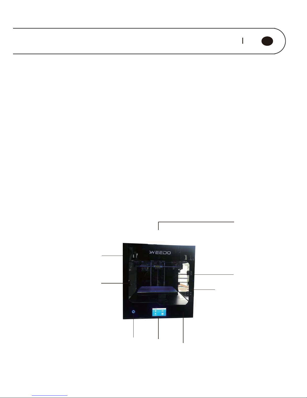
2.1 Appearance Introduction
The Front View of Printer
༃
༄
༅
༆
༇
༈
༊
༉
Page 6
༃
Up Cover
༄
Front Decorative Panel
༅
Left Side Door
༆
Power Switch
༇
Touch Screen
༈
Front door
༉
Acrylic Platform
༊
Filament Hold
༉
༉
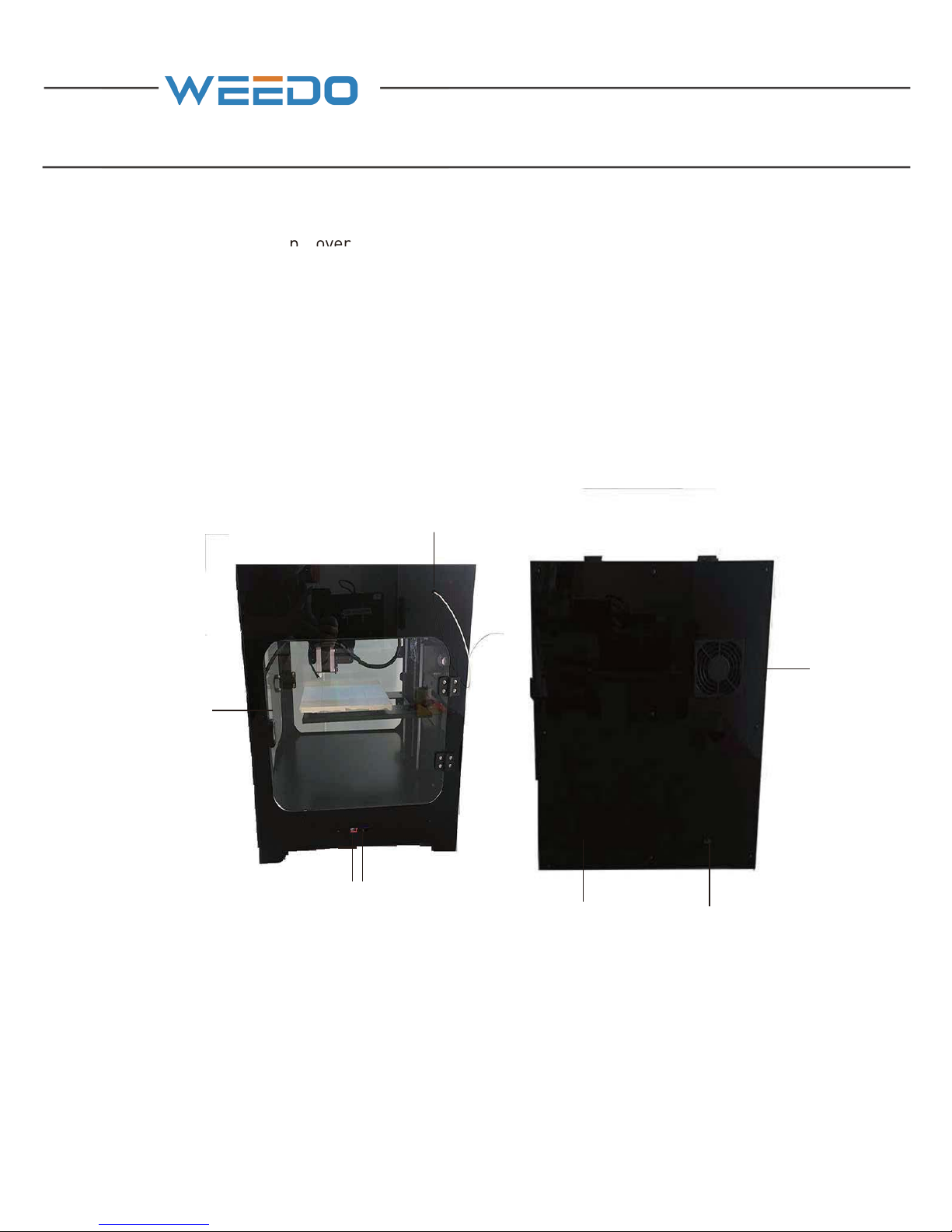
The Right View and Back View of Printer
༃
Right Side Door
༄
SD Card (7) Socket
༅
USB Line Socket
༆
Power Socket
༇
Chassis Fan
༈
Air Filtration Fan
Filament External Entreance
༃
༄༅
༆
༇
༈
Page 7
5 6
GB
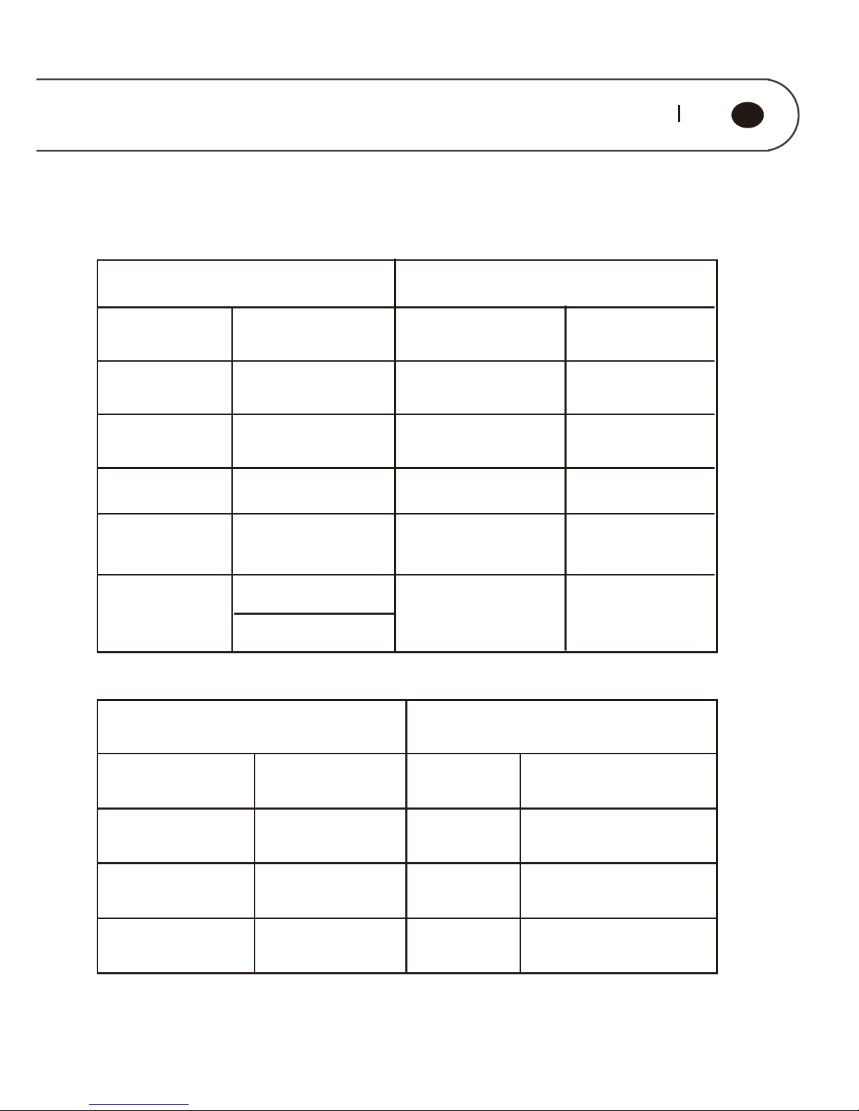
2.2 Technical Parameters
Printing Parameters
Machine Parameters
280 *200*200 mm Display Screen Model
English/German/F
rench/Italian
Layer Thickness
0,1 ~ 0,5 mm
490 * 450 * 510mm
Nozzle Diameter
0,4 mm Machine Weight 25 kg
Machine Color
Black
230 V ~ 50HZ,2A
Printing Speed
20 ~ 150 mm/s
Positional
Accuracy
Z axis 0.00125mm
XY axis 0.011mm
Filtration System
Three Layers of
Mesh Filter
Consumable Parameters
Software Parameters
Consumable
Type
PLA/PLA Pro/
PVA /ABS
Printing
Software
Cura WEEDO Version/
ReplicatorG WEEDO
Consumable
Diameter
1,75 mm STL/GCODE/OBJ
Consumable color
Optional for
multi-colors
Windows/Linux/IOS
Printing
Method
USB/SD Card (7)
Machine Size
Power Input
File Format
Operating
System
Print Size
Nozzle Number
2
11
1
Notes: 1:Special needs
*2 *2
Page 8
3.INSTALLATION OF PRINTING SOFTWARE
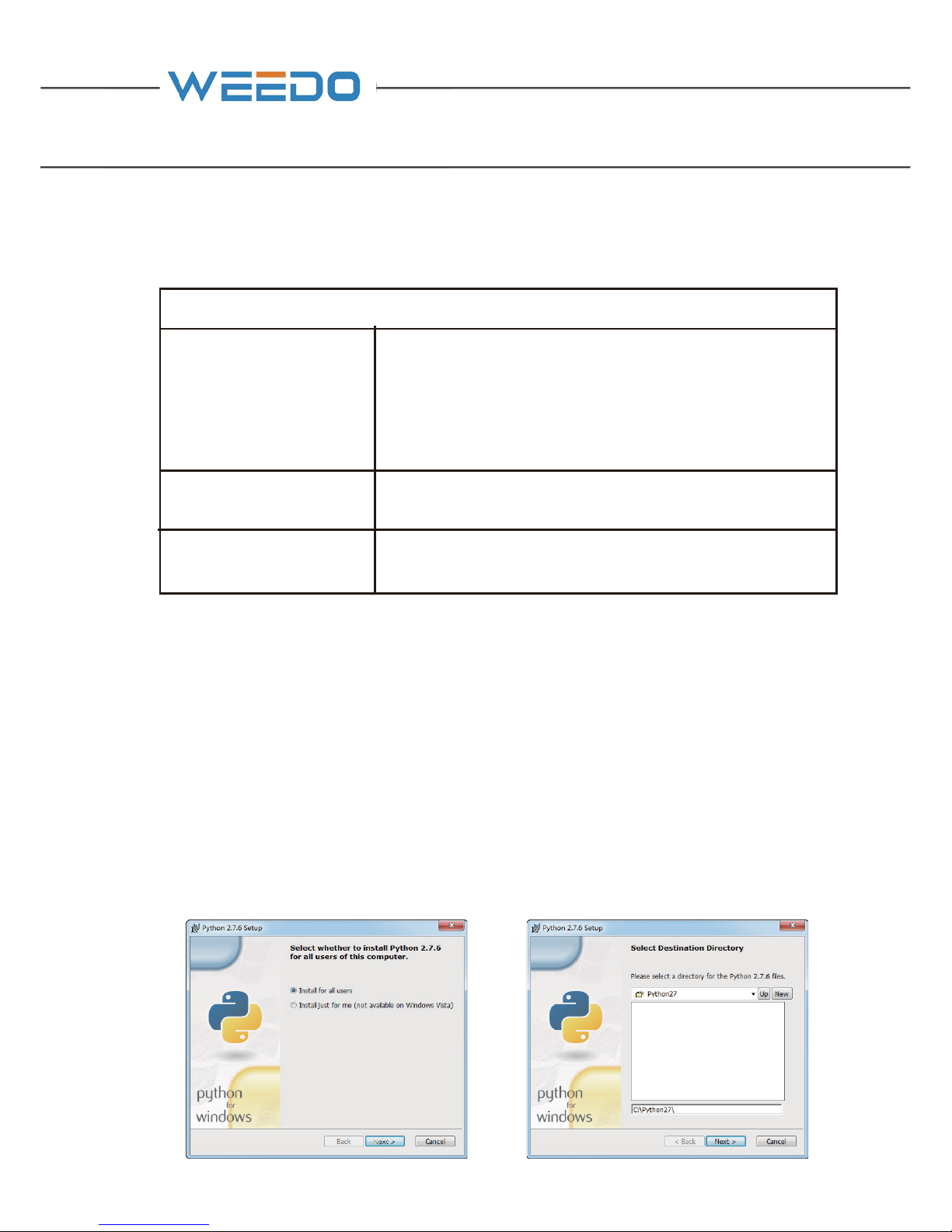
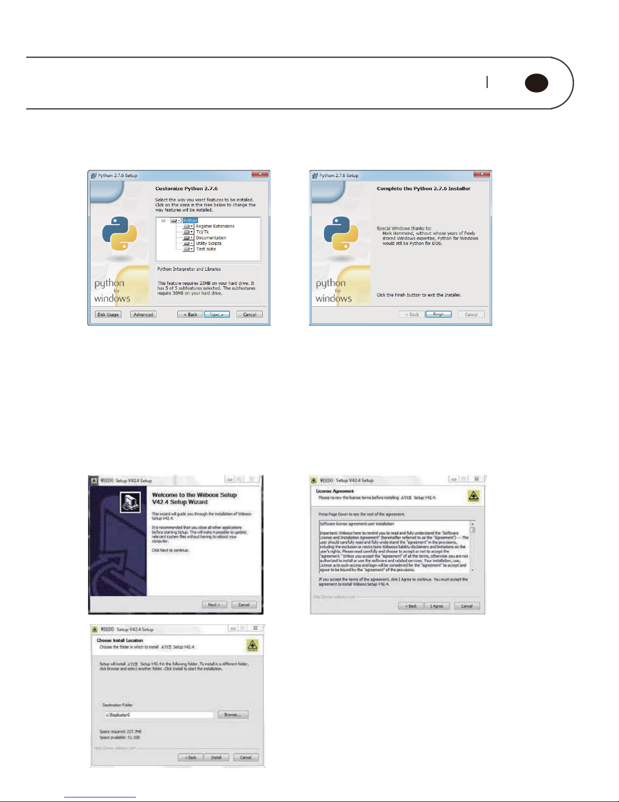
3.1. Install Python
Python is an object-oriented、literal-style computer programming language.
ReplicatorG slicing software (skeinforge) is written in Python language. And so
Python must be installed before installing ReplicatorG software,Otherwise,
ReplicatorG software can not start .Open the CD (14) or go to official website to
download the installation package(www.ayce.ch). Runing the python-2.7.6.exe,
execute the installer and follow the directions to install the software. Please choose
the defaultpath as the Destination Directory, otherwise the following ReplicatorG
software could not find the library path.
Software Type Software usage
Weedo _V44EN.exe
(ReplicatorG)
Thisprogramisusedtotransfer"gcode"and"x3g"file
to"stl"file.Whenthe3Dprinterconnectedtocomputer
by a digital wire, youcanuseReplicaterGtocontrolthe
printingfromcomputer.
Python _ 2.7.6.msi
Python is a must program for ReplicatorG, and it makes
ReplicatorG can achieve model data format conversion.
Cura _WeedoV1.2.5.exe
Cura is an open source software. It can be used to slice
3D Model.
Page 9
7 8
GB
Choose the default option to install all the features.
Run the software installation package from CD (14), WEEDO_V42.4_EN, in the
installation wizard window, click “next”→“I Agree” to continue. In the window of
selection installation path window, please use the program default route.
After the installation is complete, click Finish to exit。
3.2. The Installation of ReplicatorG WEEDO Special Use Version
Page 10
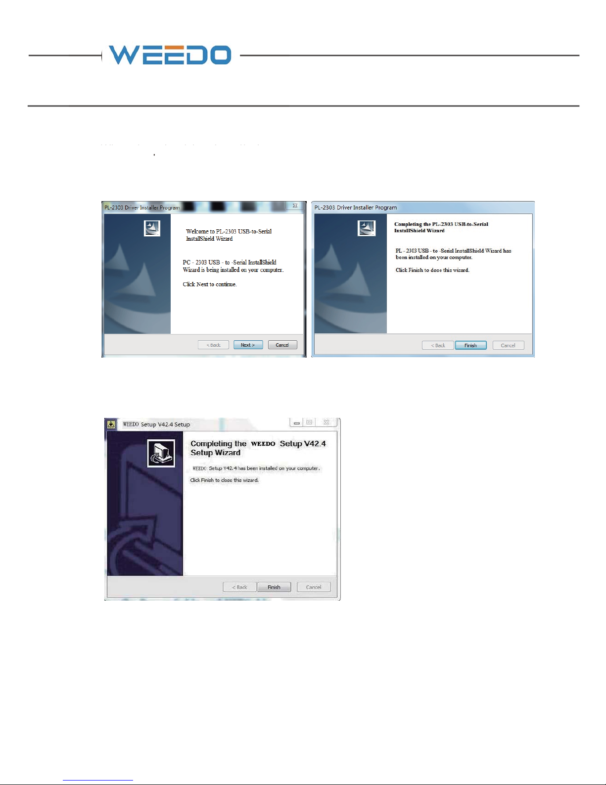
When the print driver installation screen pops up, click "Next" to continue. After the
printer driver installation is complete, click "Finish" to exit.
After the software installation is complete, click "Finish" to exit.
3.3. The Installation of Cura Special Use Version
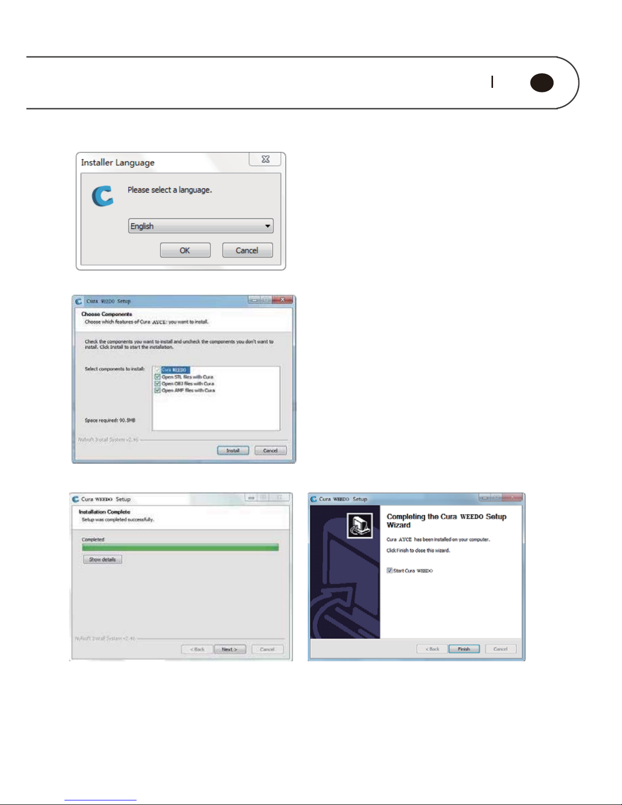
Run the software installation package from CD (14), Cura-14.07-WEEDO, in the
installation wizard window, click “install”→“Next”→“Finish”. In the window of
selection installation path window, please use the program default route.
When the print driver installation scr
Page 11
9 10
GB
Note: Cura installation path is the root directory of Disc C
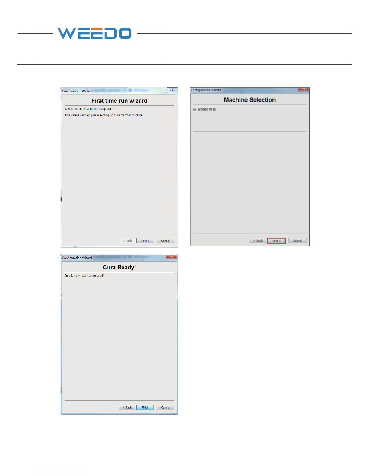
When it is first time to use Cura software, go to the guide interface, click “Next”, go
into the computer model selection interface, select WEEDO F152, click “Next”, go to
the ready interface, click “Finish”, the installation is completed.
Page 12
Page 13
11 12
GB
4.PRINT THE FIRST MODEL
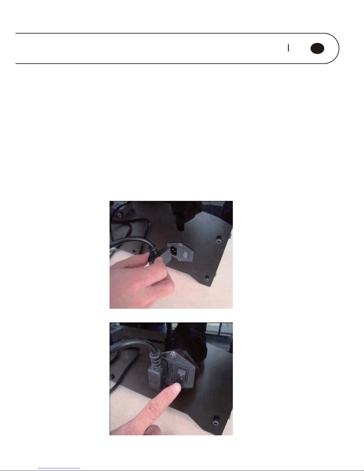
4.1. Attaching the Power Cable (4)
Pick up the power cord from the accessory box, put the male head into the power
outlet and female head into the 24V external power wide-mouth adapter; connect
the 24V external power round port to the power input jack at the back of the printer.
External 24V power supply
Page 14
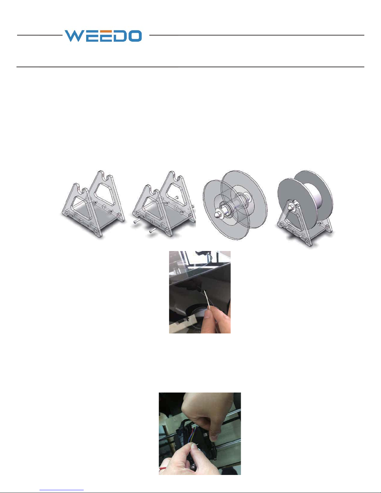
4.2. Assembly of Filament
Assemble the filament support (2) according to the “Instruction of Filament Support
Setting”, and after it’s done, find out one end of filament from the material tray (2)
and sent it to the feed pipe at the back board of printer, until the filament thread out
from another end of material pipe.
Open the cover plate on the printer; pull out the filament around 20cm from the
material pipe. Break straight the end of filament, right hand presses down the
handle of nozzle, and left hand holds the filament and plug it into the feed inlet,
insertion depth is about 5cm.
Page 15
13 14
GB
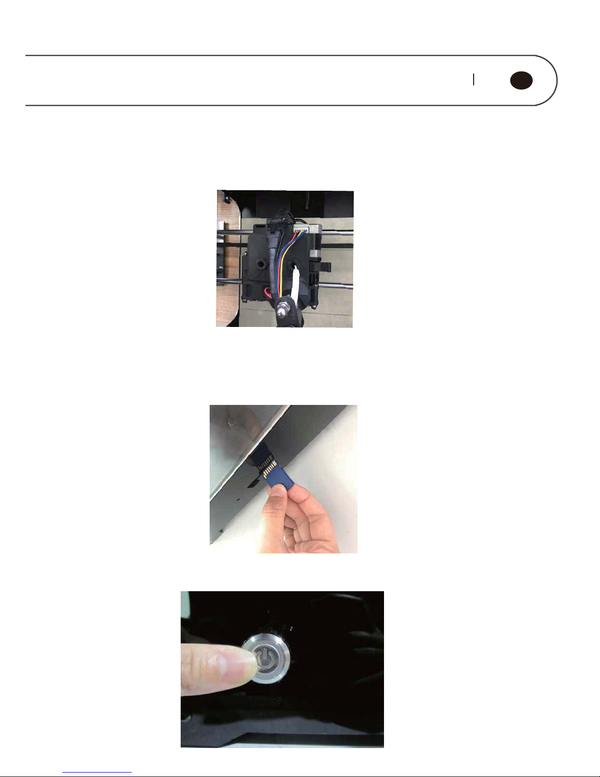
Stuff the excess material filament back to the feeding pipe, and then place the
feeding pipe on the feeding hole.
4.3. Printing Preparation
Take out the SD card (5) presented in accompany with printer, and plug it to the card
slot.
Press down the power button at the rear panel, and start up the printer power
supply.
Page 16
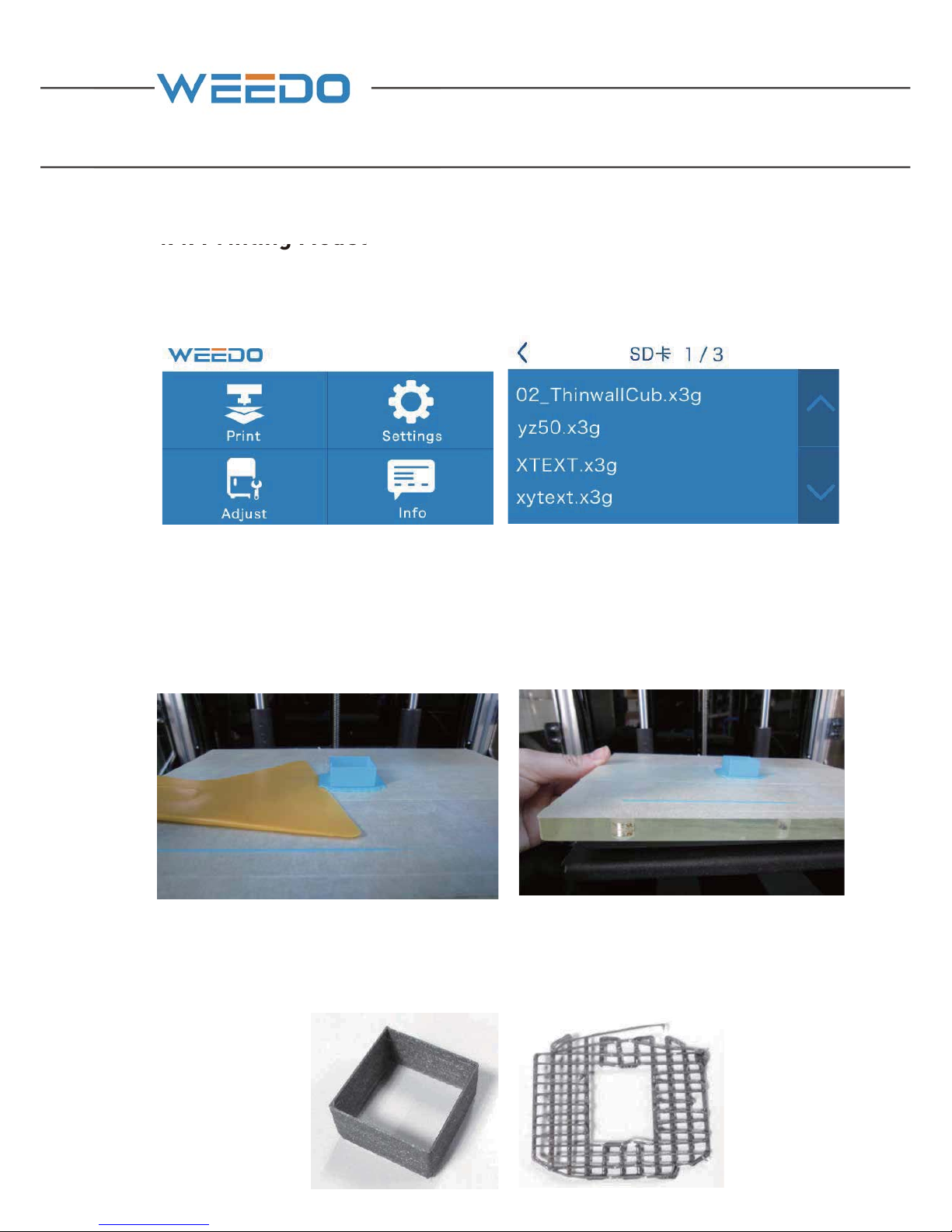
4.4. Printing Model
On the operation panel, choose “Print” the files in the SD card”→”02▁
ThinwallCub.x3g”, press it to start printing.
4.5. Removing Model
After model is completed with printing, it uses the presented plastic scraper (13) in
accompany with printer, to take the model out along with model edge, or firstly
disassemble the printing platform and take out model.
(This cube is to check whether the distance between nozzle and build plate is normal.
If the strip is of the same width and the width of the gaps between strips is 3 times of
the width of the strip, it means the distance between nozzle and build plate is
normal.)
Page 17
15 16
GB
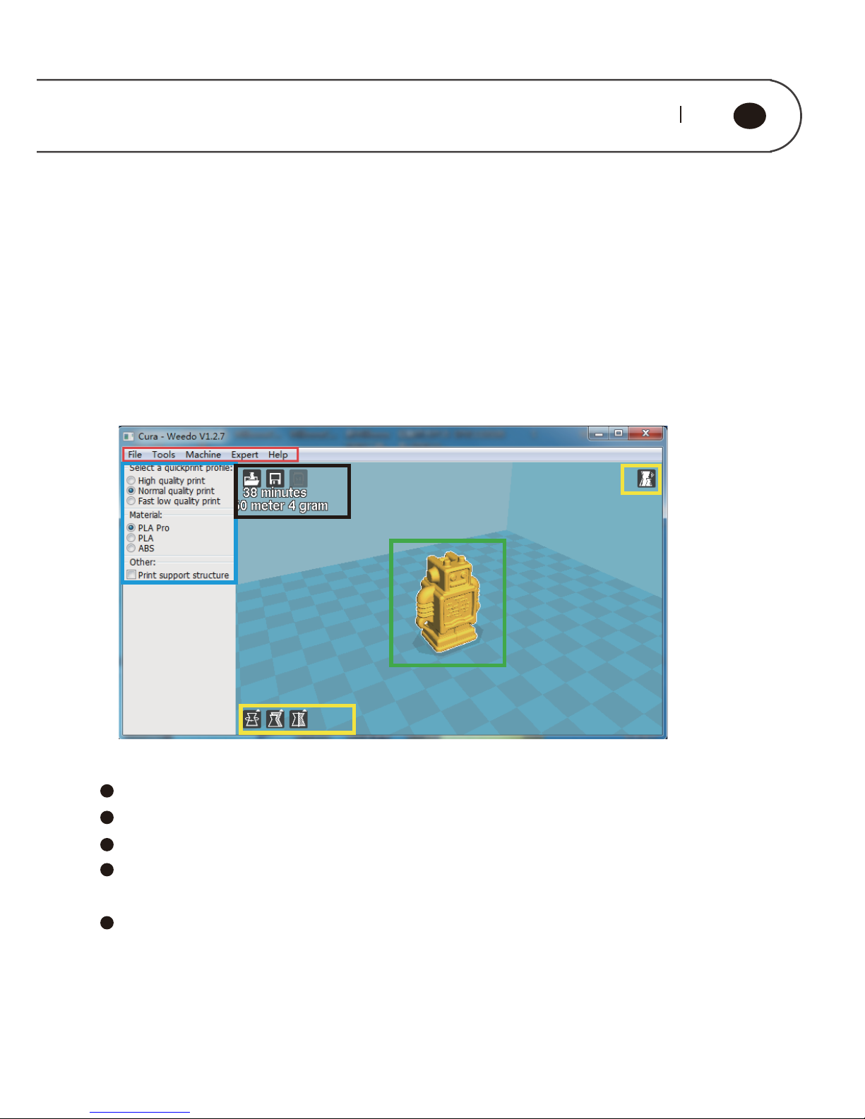
The figure below displays a typical interface of Cura
Red Box is Menu Bar
Blue Box is Printing Parameters Setting Bar
Yellow Box is used to Adjust model, and to check model
Black Box is the operation related to Printing,grey buttons displays it
can’t be used temporarily under the current condition.
Green Box is Model Preview
5.1.2. The Preference Menu
Click “File” on the menu bar ė “Preference”, enter the preference menu, as shown
in figure below, it can perform the following setting˖
5. SOFTWARE DETAILED INTRODUCTION
5.1. Cura Software Introduction
5.1.1. Basic Interface
Page 18
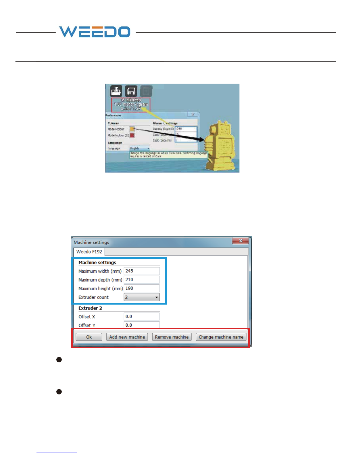
Please note: After language is switched, it can be effective only after restart.
5.1.3. Machine Setting
Dual-extruder machine use single nozzle printing
Click “Machine” on the menu bar→ “Machine Setting”, enter to machine setting
interface, as shown in figure below.
Blue Box refers to the size of machine printing platform, we have already
performed the preset according to your choice of model, please do not change these
data.
Red Box refers to the associated settings of machine, including adding new
machine model you need, delete the machine model you don't need, also can modify
the name of machine model, modification of machine model name would not
change any parameters.
Page 19
17 18
GB
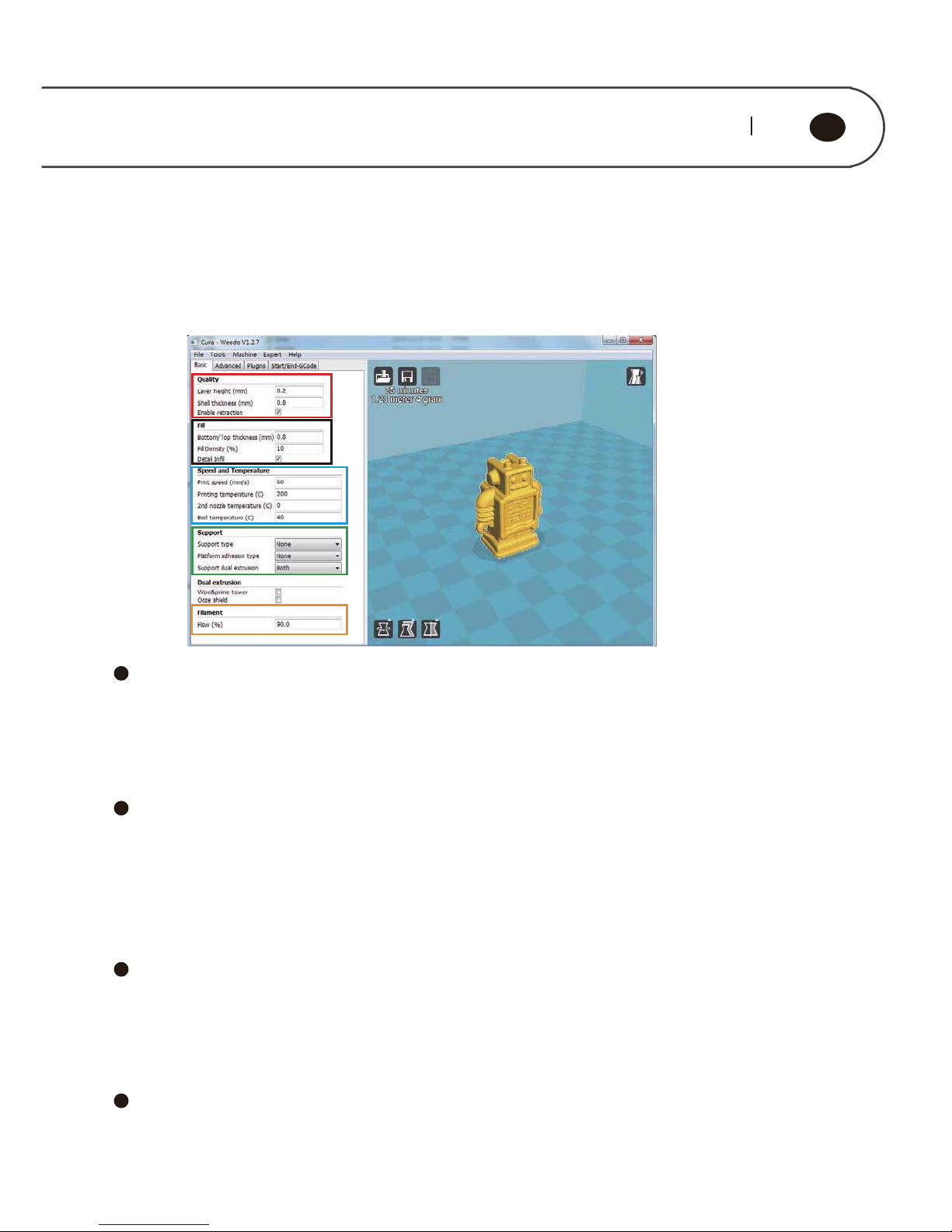
5.1.4. Printing Parameters Settings
Click “Expert” on the menu bar→ “Switch to full settings… ”, go into the complete
setting interface, as shown in figure below.
Red Box is Printing Quality Parameter.
Layer height: is the printing precision we usually refer to, and is generally chosen
between 0.1 and 0.25, the smaller the data is, the higher the model precision is.
External shell layer thickness: the thickness of outermost surface can improve the
surface quality, and is multiple of nozzle size (is also the multiple of 0.4)
Black Box is Stuffing Parameters.
Bottom and top thickness: the thickness of model bottom layer and top layer, it is
suggested to use the same parameter as the external shell.
Packed density: It refers to packed density of model. The interior of model is not
completely packed, and it would not affect the surface quality, but affect the
intensity only.
Blue Box is Speed and Temperature Parameters
Printing speed: If the printing object is relatively small, please use the low speed.
Printing temperature: it refers to the temperature of printing spray-head, the
temperature to print the PLA/PLA pro consumables is 190-210 degree.For
Dual-extruder printer it may be 170-190degree.
Green Box is Support Parameters
Support type: shown as figure below, “None” refers to not use the support,
“Touching build plate” is external support, “Everywhere” is complete support, the
support type can be choose according to the model suspending in the air.
Page 20
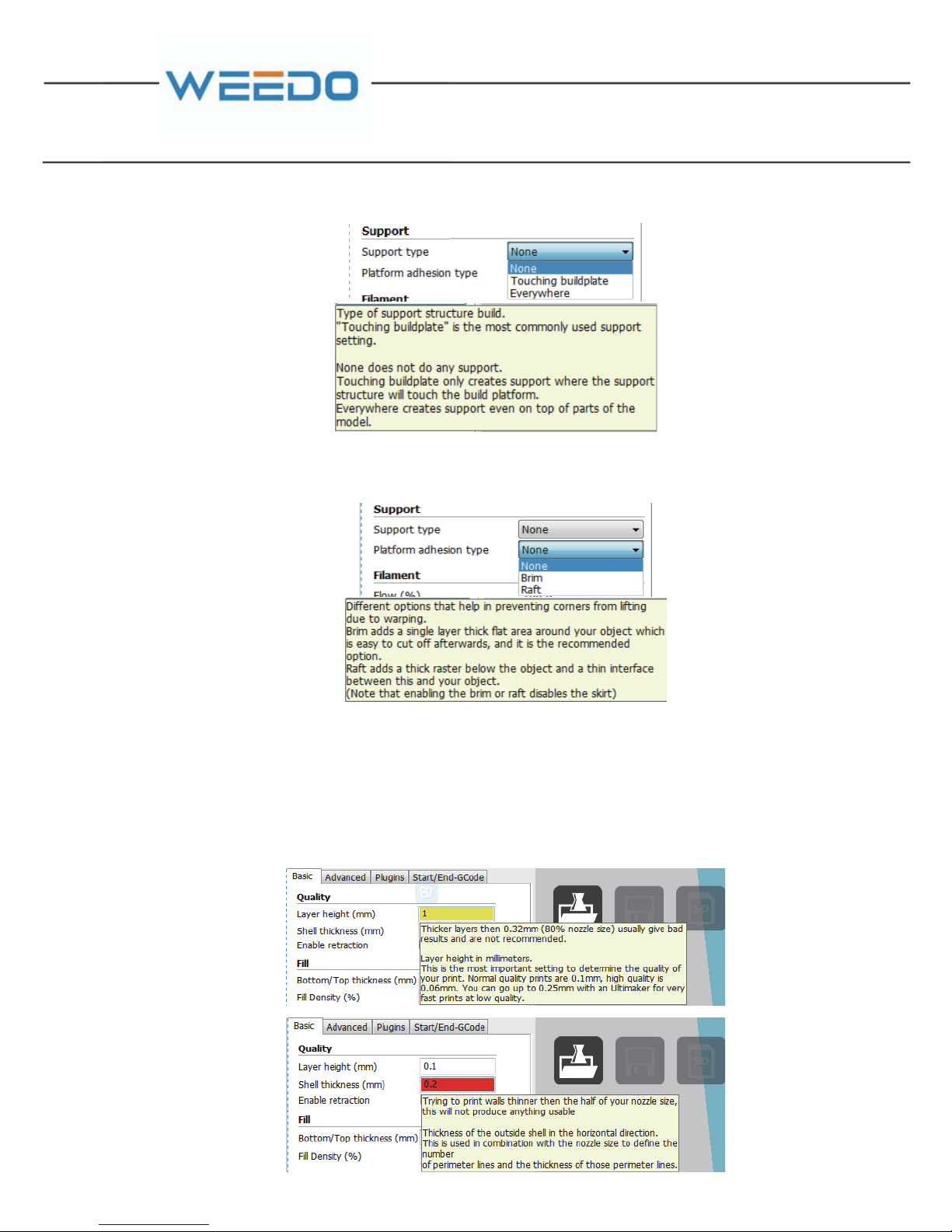
Printing platform adhesive base type: as shown in figure below, “None” refers to not
used pad, “Brim” refers to edge pad, “Raft” refers to bottom gridding pad.
◆Orange Box is the filament flow rate parameters
The filament rate parameter is generally 90%.
Please note: when it is wrong or ineffective for filling the parameters, software
would use yellow and pink to provide indication, yellow refers to warning, red refers
to error, it can be seen when the mouse hovers, as shown in figure below.
Page 21
19 20
GB
5.1.5. Model Conversion
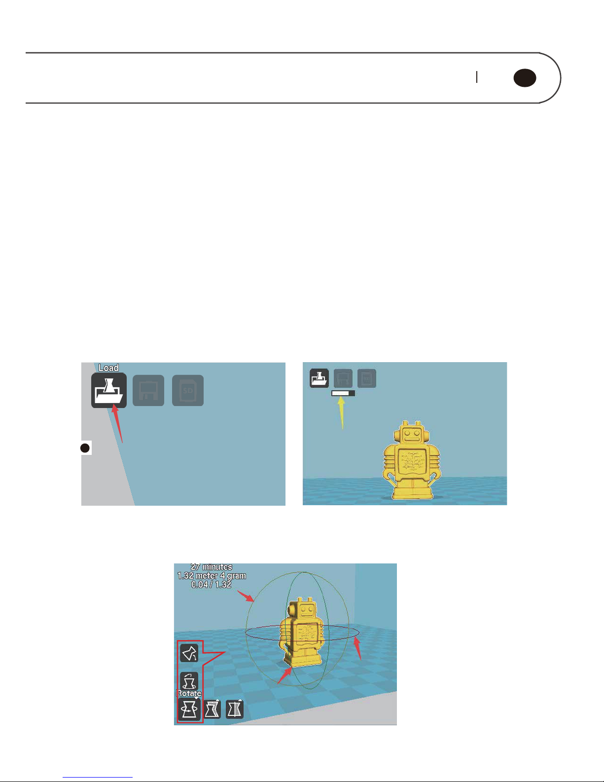
5.1.5. 1.Model Loading
Open Cura software, as shown in figure below, click the loading button of “Load” of
red arrow pointing on the interface, the model needed to print is choose in the
pop-up window. Please note: Yellow arrow pointing is the progress bar, Cura
section engine is always started, when model or parameter is changed, engine
would re-start slicing. To the computer with low configuration, the frequent
modification of parameter and changing model may cause the Caton phenomenon
(E.g the software interface can not display a progress bar or the software interface
is grayed for a long time). when the engine is started, the operation speed shouldn’t
5.1.5.2. Model Adjustment
Page 22
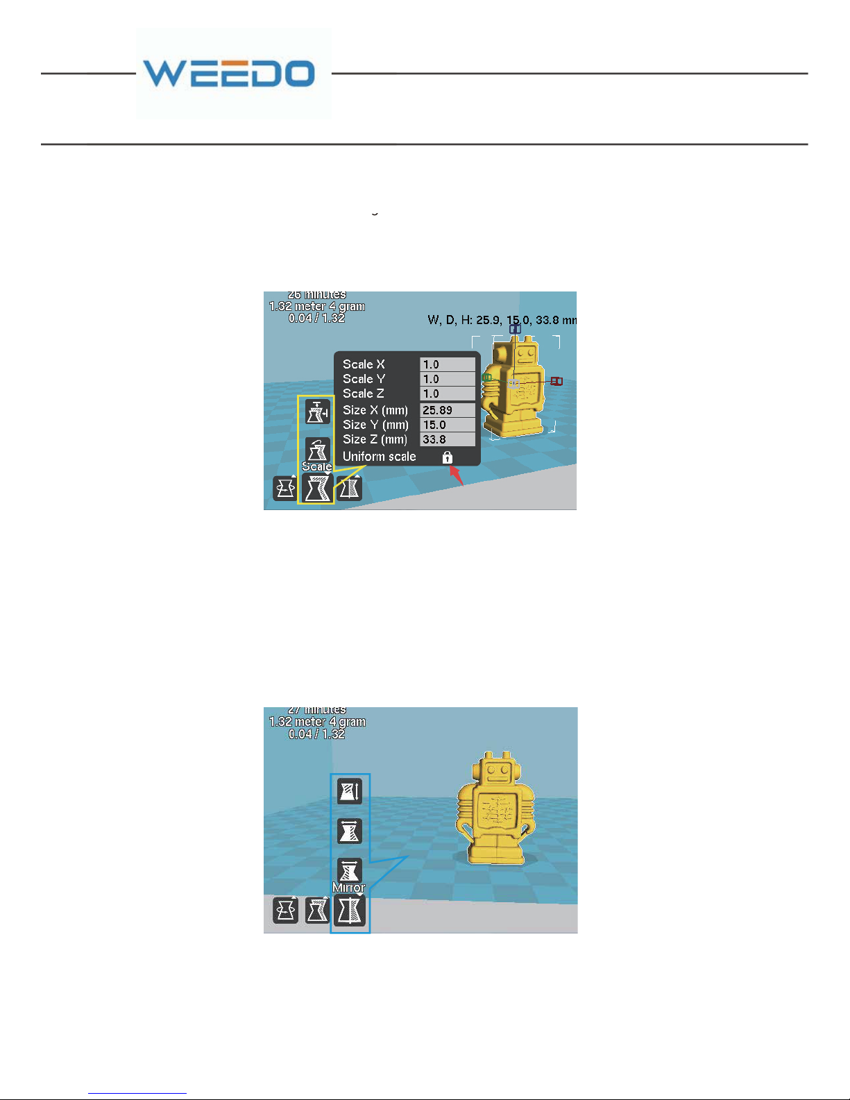
Red Box is Model Rotation Setting. Click the rotation button, and then hold the left
key of mouse, and drag the ring shape edge frame around the model to adjust the
model, it can perform rotation adjustment to the model from three directions of “X,
Y, Z”.
Yellow Box is Model Zoom Setting. Click on the zoom button, and pop up model
zoom scale and model size dialogue window. In the item of “Scale”, it inputs the
proportion factor needed with zoom to adjust the model size. When the icon “” red
arrow pointing is at the lock-out state, any direction zoom would perform the zoom
to the model entity; When the icon “” is at the open state, it can perform the single
direction zoom to the model.
Blue box is model mirror image, click the mirror image button, three buttons would
pop up and they represent the mirror images of three directions of Z, Y, X
respectively.
Red Box is Model Rotation Setting.
C
Page 23
21 22
GB
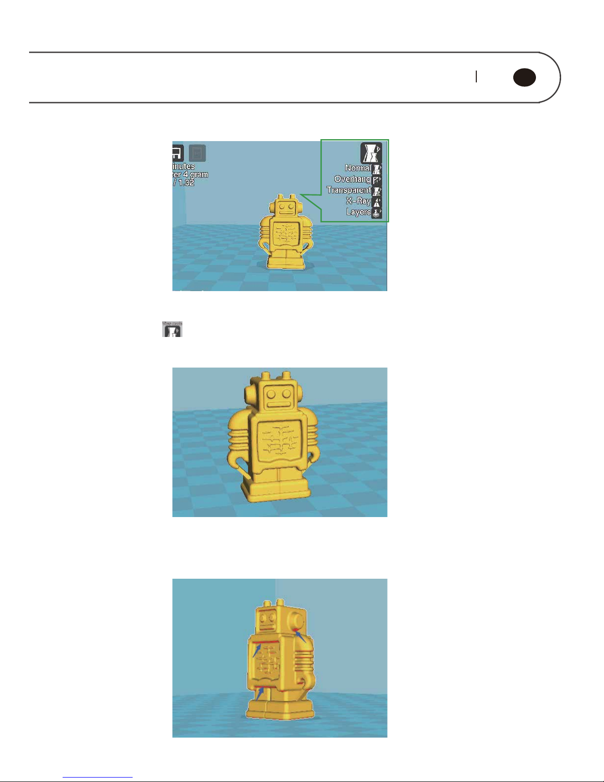
Green Box is Check Mode Option
Click the button , five modes buttons, respectively:
“Normal” is normal mode, show the model appearance only, which is default mode
“Overhang” refers to overhang mode, and would indicate the overhang part of
model, these part may hang down in the absence of support. The red area pointed
by blue arrow is as shown in figure below.
Page 24
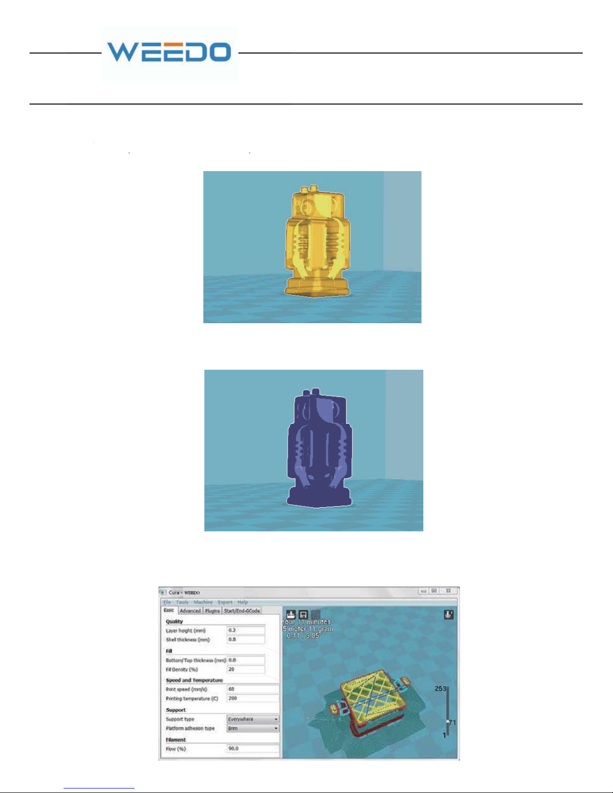
“Transparent” refers to transparent mode, and can watch the internal structure of
model.
“X-Ray” refers to X ray mode, and is similar to the transparent mode, but ignore the
surface.
“Layers” refers to layered mode, and can watch the movement path of spray-head
and support structure, as shown in figure below:
Page 25
23 24
GB
5.1.5.3. Generation of Gcode Code and X3G File
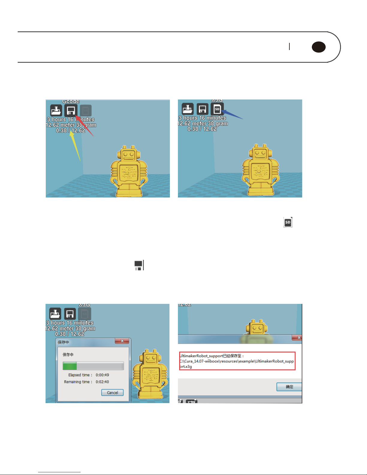
Yellow arrow refers to the data which is
result of model conversion, including
printing the time-consuming and
filament use volume. If the cost of
filament is set, it would display the
model cost. At this moment, the button
of save “ ” can be used, and click the
button the red arrow points, to generate
When the model generates code of
Gcode, the icon blue arrow points “ ”
is changed from grey to white, and it
indicates the button can be used, and
clicks the button to generate X3G file.
When x3g file is generated, it would pop
up the progress bar as shown in figure
above.
After x3g file is completed with save, it
would pop up the indication as shown in
figure above, namely it is x3g file storage
path.
Page 26
5.2. ReplicatorG Software Introduction
5.2.1. Basic Interface
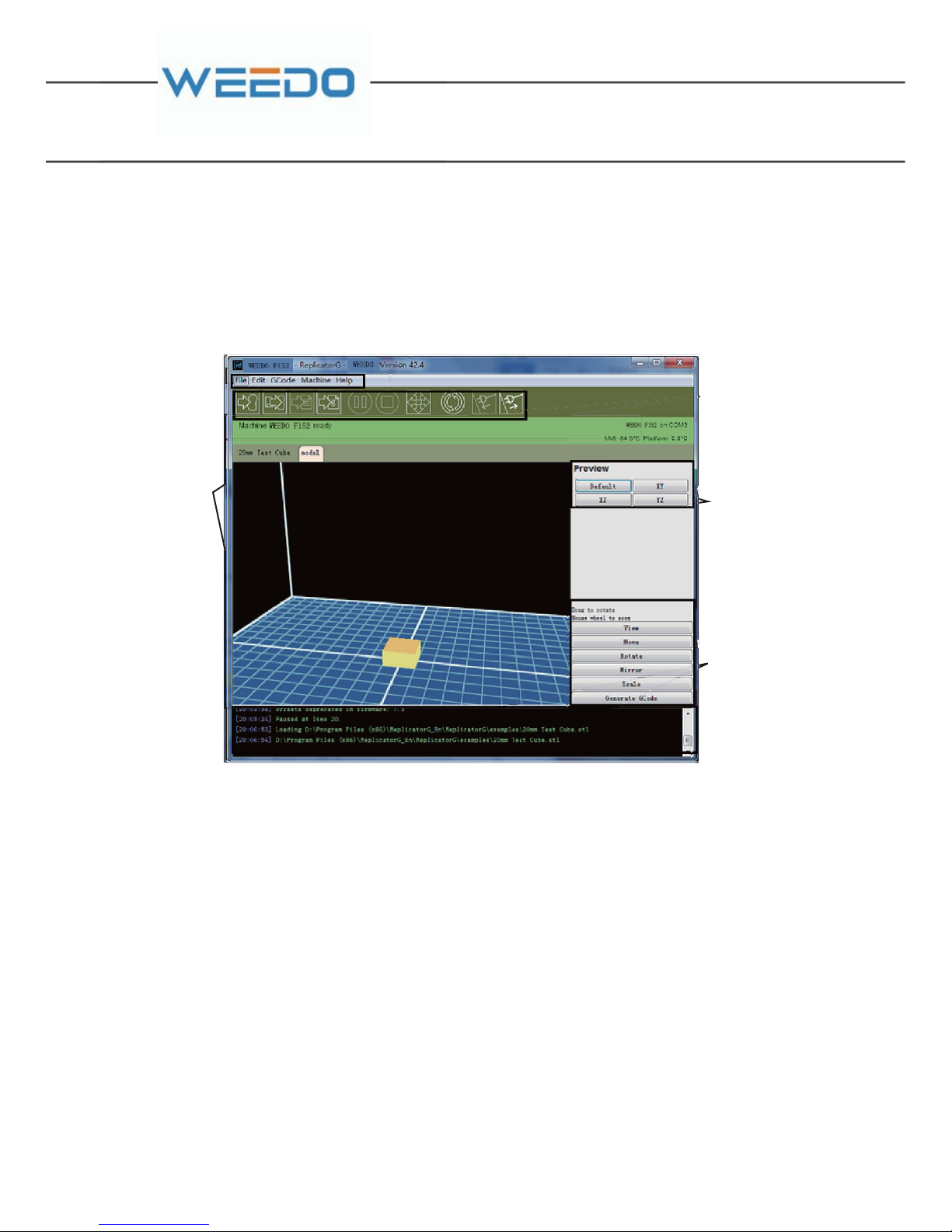
The software interface of ReplicatorG is as follows.
1.Menu bar. The main menu has five options: File, Edit, GCode, Machine and Help.
You can find the detailed information in 5.2.1.
2.Tool bar. It displays ten most common used function, please refer to 5.2.2 for
details.
3.Status bar. It shows the status of your connection to your printer, the current
temperature of the nozzle and your build progress.
4.Model/code preview. The 3D model you've selected will displayed in the ”model”
tab, and when the GCode generation is completed, you'll see a "Gcode" tab appear
beside your ”model” tab.
5.Model control panel. You can control different parts of your machine from the
control panel include such operations as move, rotate, scale and so on.
6.Message output window. It shows you the output messages the machine and the
skeinforge (slice Software) running in the background. (Note: We use a tool called
Meaubar
Tool b ar
Status Bar
Model/Code
Preview
Model Control
Panel
Message Output
Window
M
M
M
M
Page 27
25 26
GB
5.2.2. Menu bar
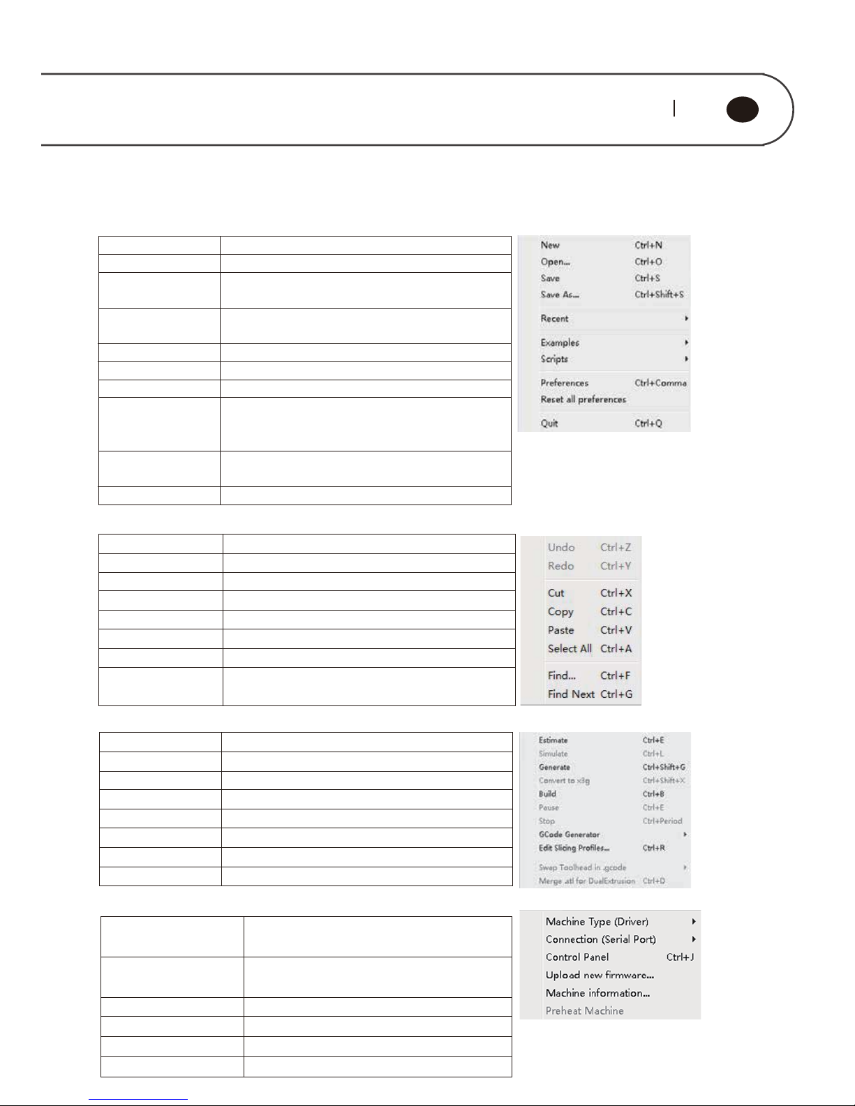
1.File
New: Create a new GCode file
Open PrintSTL model or GCodefile
Save Allows you to save the current STL model or
GCode file
Save as
Allows youto save the modified STL model or
GCode files as specified file name
Recent
Open therecent file list.
Examples
Open thesamplemodel list
Scripts
Open the script file list
Preferences
Open the parameter setting window (if you are not
clear about the specific function of some settings,
do not change them).
Reset all
Preferences
Reset all software parameters to the default
settings
Quit
Exit the software environment
2.Edit
3.GCode
Machine Type
(Driver)
Choosethe machine type
Connection(Serial
Port)
Choose the serial port to connect the
machine to the computer
ControlPanel Openthe manual control panel
Upload new firmware Update the firmware online
Machine information Display the machine informa tion
Preheat Machine Preheat theheat plate and the nozzle
4.Machine
Undo Cancel or modify your previous actions
Redo Redo ormodify your previous actions
Cut Cut code(onlyeffective in the GCodetab)
Copy Copy code (only effective in theGCode tab)
Paste Paste code (onlyeffective in theGCode tab)
SelectAll Select code(only effective in theGCode tab)
Find Findcode (only effective inthe GCodetab)
Findnext Find next code (only effective in the GCode
tab)
Estimate Estimate thebuildtime
Simulate Simulation build
Convertto Gcode ConvertSTLmodel to GCode
Build Build the object from Gcode file
Pause Pause a print
Stop Stop a print
GCodeGenerator Choose the Gcode Generation tool
Edit Slicing Profiles Edit Gcode Generation Profiles
Page 28
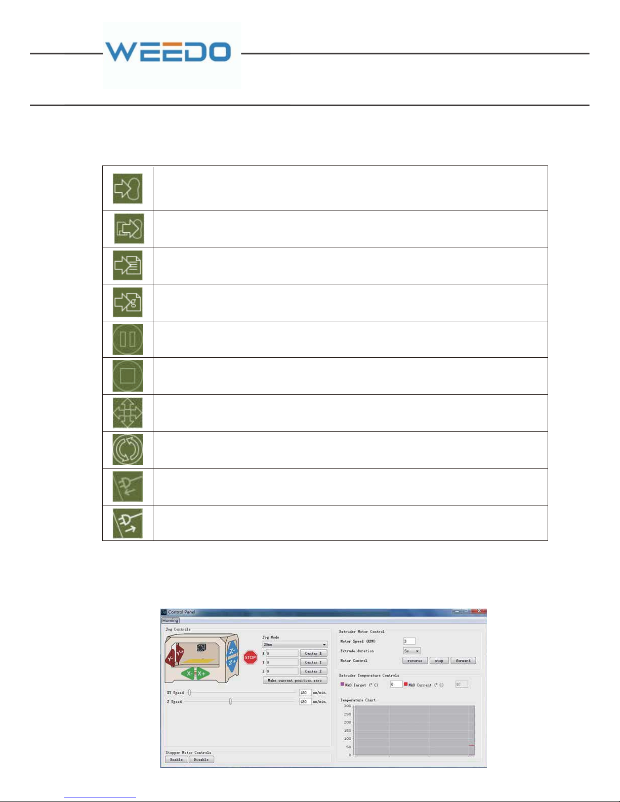
5.2.3. Tool Bar
Start a printvia USB,if the STL model has not converted toGcode,the software will firstly
use The previous conversion parameters to start convert the model before build your
object
This will allow you to print one of the list of the files currently on the SD card ( 7) in your
machine
Convert your Gcode file to an s3g file and save it
Opens up the Generate Gcode window
Pause a print
Stop a print
Open the manual control panel from which you can control different parts of your
machine.
Reset the machine
Connect to your machine
Disconnect from your machine
5.2.4. Control Panel
Click the tool bar and open the Control panel as follows, by which you can control
the movement of the XYZ axels, the build plate and the nozzle.
.2.3. Tool Ba
r
Page 29
27 28
GB
The left of the screen is a sketch of your machine, on the sketch exist several arrow
buttons of the Jog Controls of the XYZ axis. Click the corresponding button of each
axis, the motor will operate accordingly. The right boxes beside the sketch show Jog
Mode control, you can choose the movement distance of every click. Below the
sketch you can adjust the speed of each motor.
The right of the screen displays control boxes of the motor controlled the nozzle.
You can choose the Motor Speed, Extrude duration and the direction of the motor.
Note: Only when the nozzle has filament in it and the nozzle has been heated to the
proper temperature, you can let the motor make a positive or reverse movement.
Otherwise the motor gear will slip when wear occurs and seriously affect the life of
the nozzle.
The lower right part is the temperature control of the nozzle. You can change the
temperature of it by inputting the figures into the text boxes. If you change the
temperature of the nozzle simultaneously, the machine would preheat the nozzle.
The lower left part enables you to decide whether you want to control the stepper
motor.
5.2.5. Toolbar of Control Panel
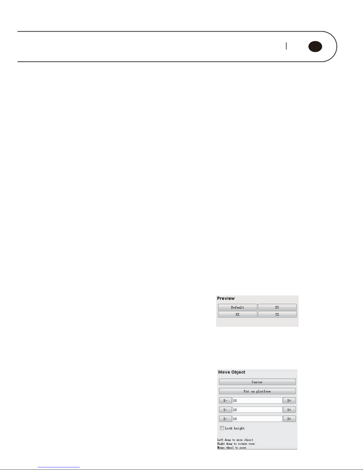
1.View
Click the “View” button in the toolbar on the right. You
can click and drag in the preview window to rotate your
view by using both left and right mouse button. Click
the button in the Preview window reset or change your
view direction.
Default
XY
XZ
Reset the object to a default orientation
Top view
Frontview
YZ Side view
2.Move
Go to the "Move" panel. Click and left drag to move your
object in the Preview window, click and right drag to
rotate your view direction. Click the button in the Move
panel to move the object by specific amounts.
Page 30
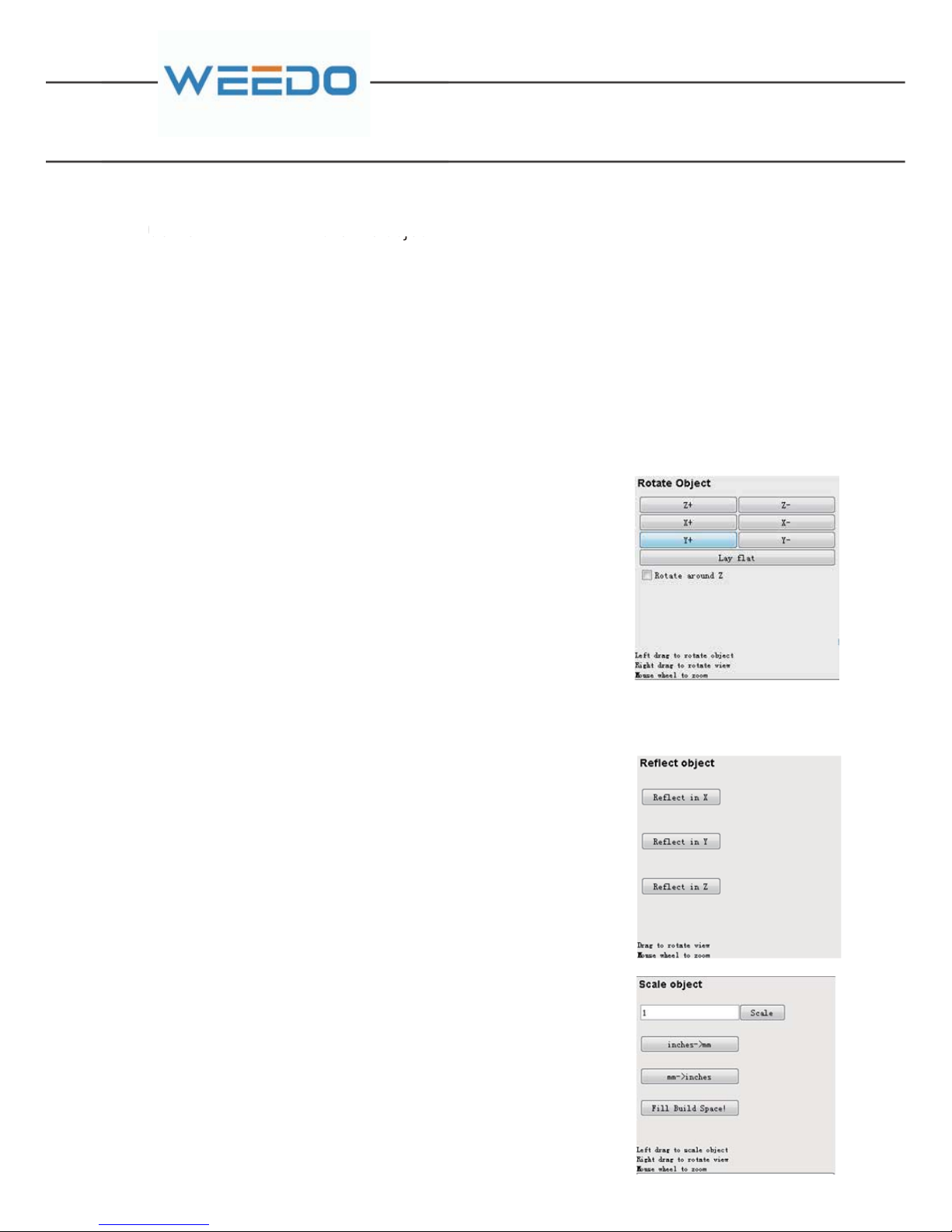
Center Move the object to the center of the platform
Put on platform Place the object so its bottom rests on the
build platform
Note: Be sure to use the above two instructions to move the object to the center of
the platform and place its bottom on the build platform when converting the
GCode, otherwise it may damage the nozzle.
Lock the height Lock the Z axis coordinates of the object, so you can only drag the
object in XY Plane.
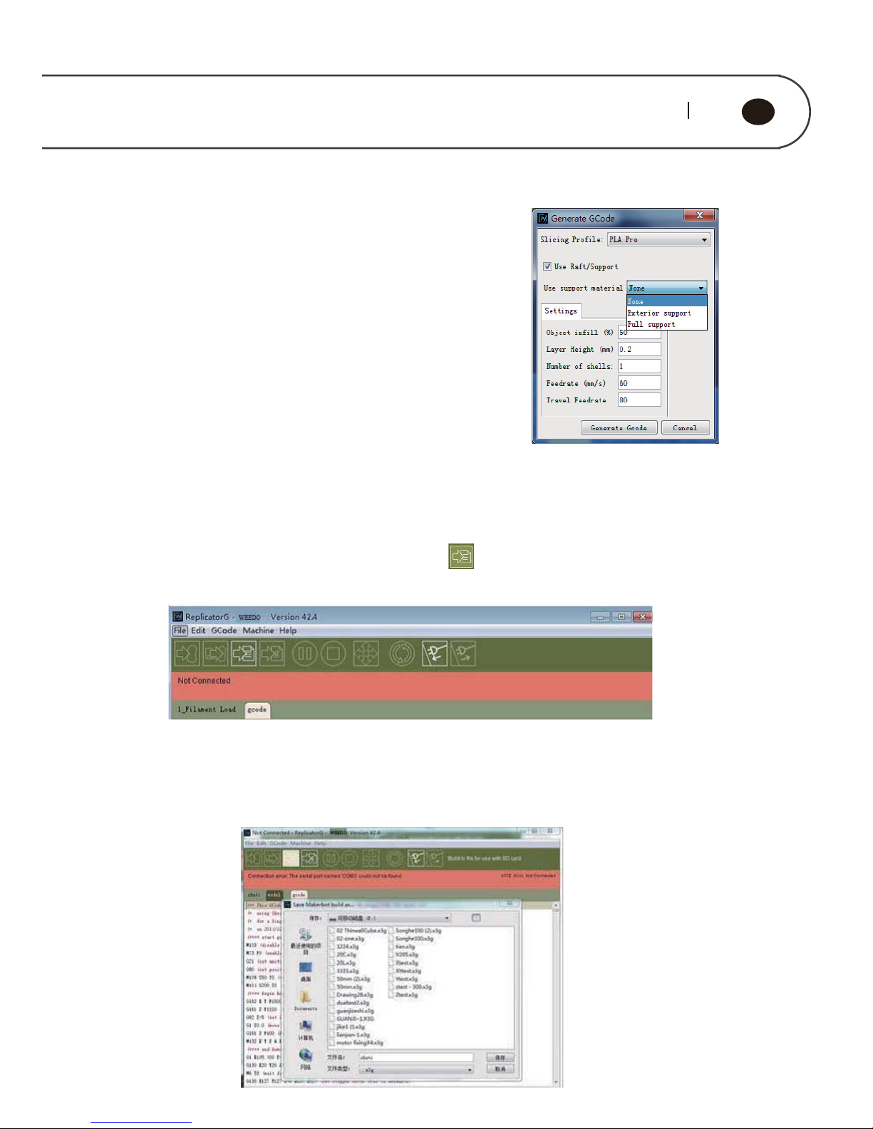
3.Rotate
Click on the "Rotate" button in the toolbar. Left drag to
rotate your object in the Preview window, right drag will
change your view direction. You can also use the individual
axis buttons to rotate your object in 90° increments in the
Rotate Object panel.
Lay flat Make the bottom of the object oriented
correctly in relation to the platform
Rotate around Z If check the checkbox, you can only
rotates the object in the Preview window
around the Z axis.
4.Mirror
Turn to the “Mirror” button. Click the buttons in the
Reflect Object panel to reflect the object in X, Y or Z axis.
5.Scale
Click on the "Scale" button at the bottom of the toolbar. You
can click and drag in the Preview window until the object is
the desired size, the scale ratio displays in the Scale box.
inches->mm
mm->inches
Full Build
Spaces
The size unit of the object changes from
inches to mm, enlarging the size 25.4
times of its ordinary size.
The size unit of the object changes mm
to inches, shrinking the size to 25.4
times of its ordinary size.
Make the object as large as your
machine can print it.
Page 31
29 30
GB
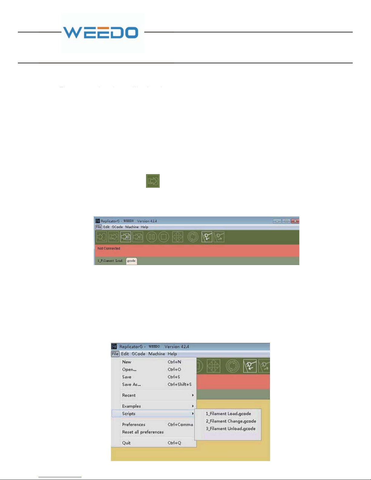
5.2.6. Generate GCode
Click the “Generate GCode” button at the lower right, the
following parameter setting window pops up.
1.Slicing Profile. You can choose ABS or PLA from the
dropdown menu.
2.Use Raft/Support. You can choose whether you need a
raft or support in this checkbox.
3.Printing parameters. You can change some settings
such as Layer Height, Object infill, Feed rate and so on;
these settings are described in more detail in the next
section.
5.2.7. x3g File
Start the ReplicatorG, after GCode generation is completed (see section 5.2.5 for
detailed GCode generation process), click the third button on the toolbar to
convert GCodeto x3g file before being sent to your machine.
A pop-up window prompts you for the file name and save path to save your object.
Note: Do not support a file name written in Chinese characters and the file name
has a limitation within 20 characters.
Page 32
The conversion time will take about 15-30s according to the size of the Gcode file.
After this process, insert the SD card (5) into the SD card slot (6) on the card reader
and connect it to the USB interface on the computer. Copy the saved x3gfile to the
root directory and then eject theSD reader (6).
Insert the SD card (5) into the SD slot in the machine, there are two ways to start
building a project using x3g file.
Method 1: Build a project from SD card (5) when the computer connecting to the
machine
Chick on the second button , the pop-up window will list all the x3g files in the
SD card (7). Choose your file and click “Y” to continue. The ReplicatorG can monitor
the real time progress of your object and the temperature of the nozzle.
Method 2: Build a project offline by the control panel, the specific process in
described in section 6.3 in detail.
5.2.8. Common Used Scripts
The Commonly used function of the scripts comes with the software such as
Filament Change and Plate Leveling. Select the “File-> Scripts” from the menu,
open one script and then click the first button on the tool bar to run the script.
The conversion time will take about
Page 33
31 32
GB
6. Operation Panel Setting
There is SD card slot at the right side of 3D printer, which can directly print the
model file in the SD card.The filament-replacement, debugging and other operation
can be controlled on the touch panel.
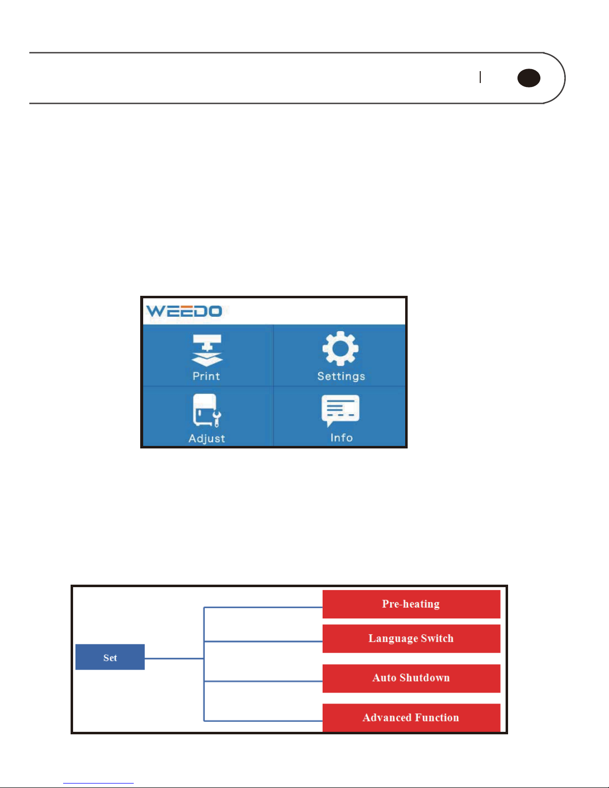
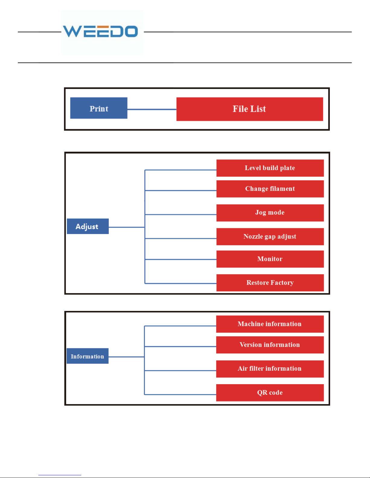
The menu tree of touch screen panel is shown in the figure below, the menu is
divided into three layers, and menu structure may be adjusted for firmware
upgrades.The left-side is the start menu, right side is submenu.Click to enter the
submenu,click the return key on the top left corner to return to the previous menu.
6.1. Operation Panel Introduction
Page 34
6.2. THE COMMON OPERATION ON THE OPERATION PANEL
6.2.1. Print
Page 35
33 34
GB
6.2.2. SETTINGS
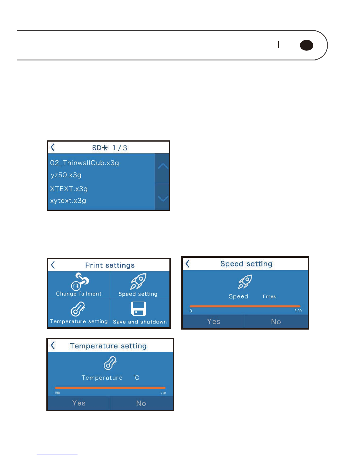
In the start menu, choose “Print”to enter the SD Card file list.This machine support
English and Chinese file name models.The list is displayed with x3g format file in the
SD card (5) root directory in the way of reverse chronological order. Use up and down
arrow buttons to choose the files needed to print, the left top arrow button is to return
to previous menu.
After choosing the file and during printing, many operations are available for example
pause printing,quit printing,pause and change filament,speed
adjustment,temperature adjustment, save and shutdown etc.
Page 36
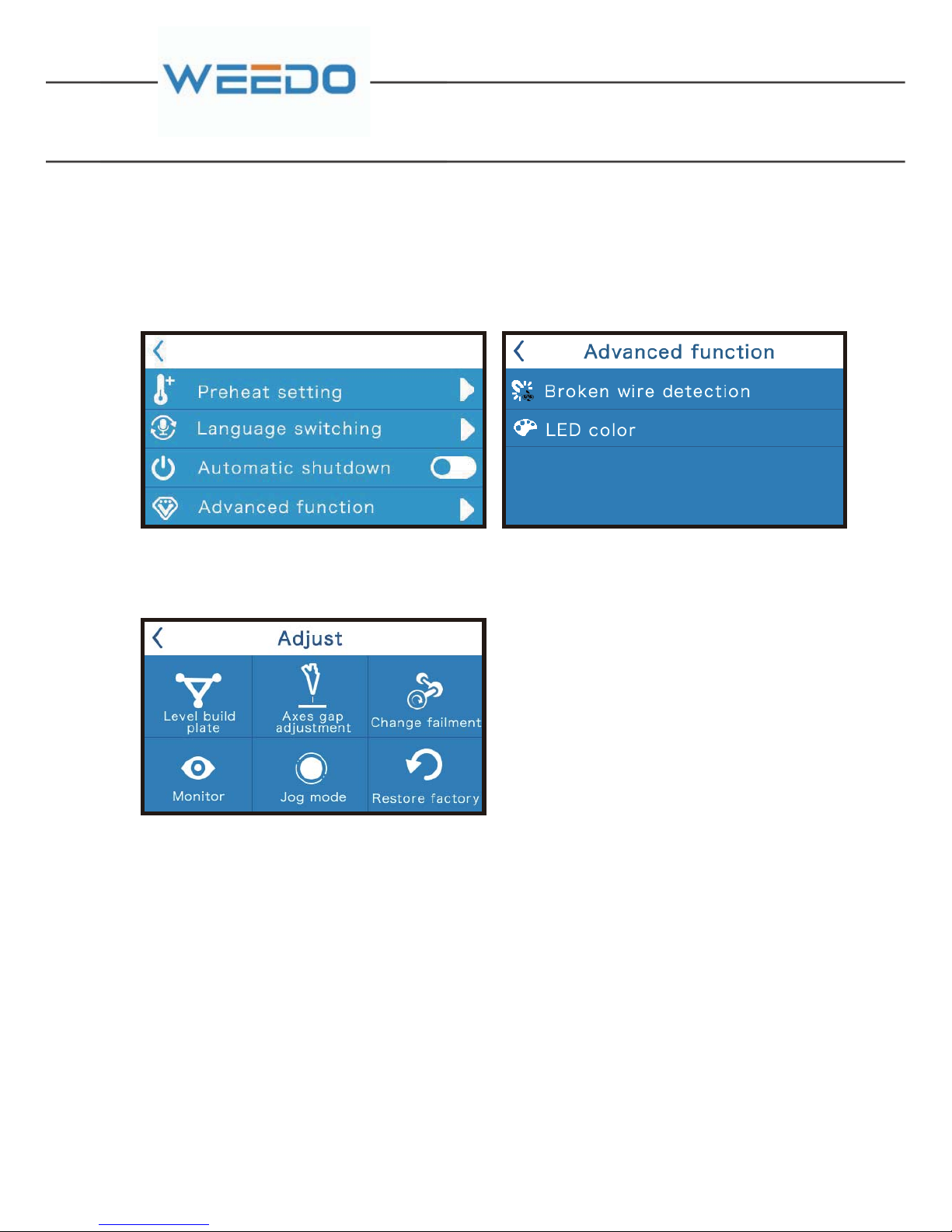
Preheat setting,Language switching,Automatic shutdown and advanced function
can be set here.
Broken wire detection and LED color can be set in “Advanced function”
6.2.3. ADJUST
Level build plate
Nozzle gap adjustment
Press “Level build plate” in the “Adjust” menu, the printer will automatically level
the build plate. Please operate according to the screen tips and keep the build plate
in rising status until hearing the sounds, it means the leveling operation is
finished.Press the return button to the previous menu.
We have adjusted well the nozzle gap for new printers,so you do not need to do it
again. When you change a new nozzle, you need to adjust the nozzle gap. Please
refer to "daily maintenance " replace the nozzle "nozzle gap calibration".
Page 37
35 36
GB
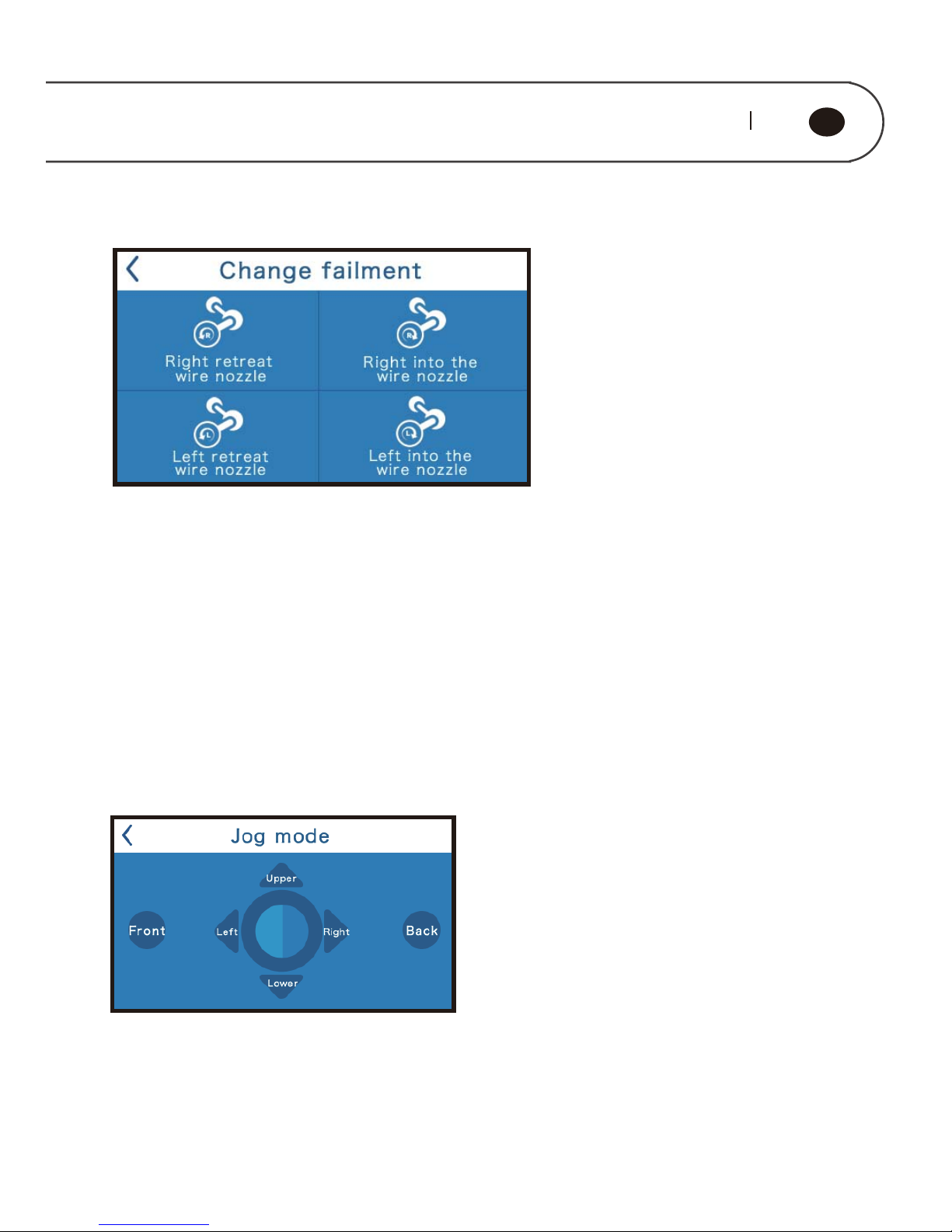
Press “Change filament” to enter the submenu and enter the manual filament
replacement interface.
Press “Right retreat wire nozzle” to enter to the filament return program. Nozzle is
heated to preset temperature, and then start nozzle motor to return filament back.
Press “Right into wire nozzle” to enter to the filament enter program. Nozzle is
heated to preset temperature, and then start nozzle motor to enter the filament.
Press “Monitor”, it will show the real-time status of the printer.
Press “Jog mode” to the submenu and enter printer jog debugging interface.
Touch screen display X, Y, Z axes three direction key, click each key can control the
axis motor move according to the indicated direction.
Change filament
Monitor
JOG MODE
Page 38
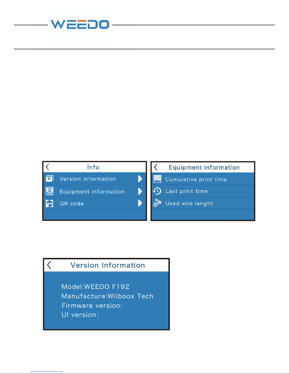
It shows the equipment version,model etc. information.
Press “Restore factory”, the printer will Restore the factory default Settings. After
pressing “Restore factory”,you had better turn off the printer and restart.
6.2.4. INFORMATION
Equipment information
Press"equipment information" to enter running time statistics interface.It shows
the cumulative printing time, The last print time-consuming and filament length,
etc.
RSTORE FACTORY
Version information
Page 39
37 38
GB
6.3 The print settings for dual-extruder printer
6.3.1. Machine settings
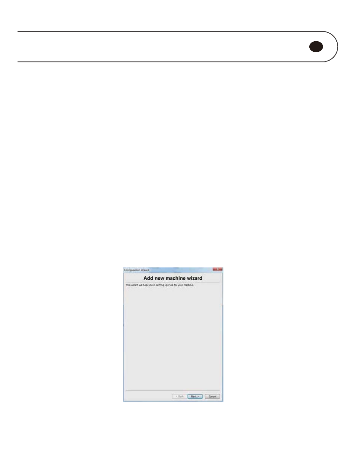
The Cura Software is suitable for the print parameter settings of single and dualextruder printer. Contrast to the single extruder printer, the parameter settings
for the second printing extruder is added to the print settings for dual-extruder
printer. When you set the parameters of the dual-extruder printing model, please
read the parameter settings related to Cura software in Chapter 5.
Start the Cura software, click on "Machine" → "Machine Setting" from the menu
bar to enter the machine settings interface, as is shown below; click on the " Add
New machine" to enter the wizard interface; click on the "Next" to enter the
machine selection interface, as is shown below; select the machine that matches
your model, click on "Next", and the machine settings interface will pop up; click
"OK" to complete machine adding.
Page 40
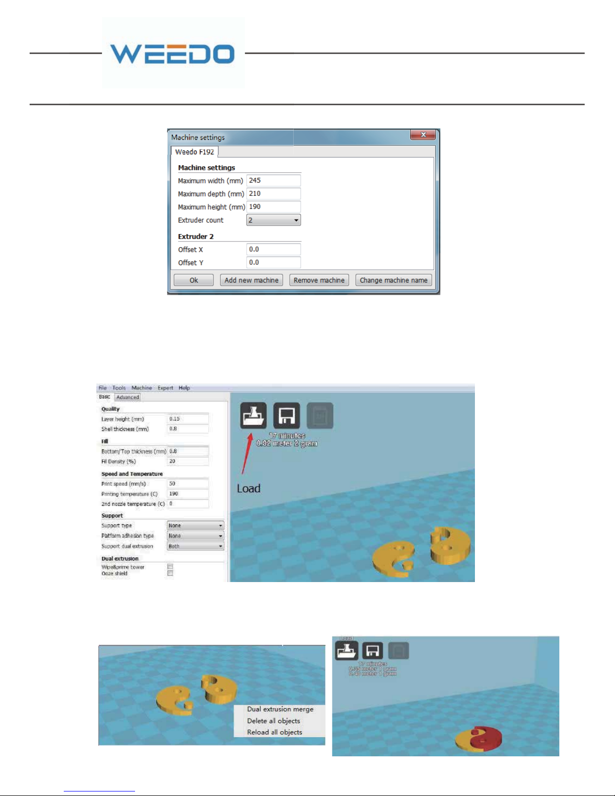
6.3.2. Two-color print settings
Prepare for two-color printing model and load the model. The model can be
directly dragged into the Cura Software (or use the Load button to load )
After right-click the printing platform and select "Dual extrusion merge" from
the window that pops up, then the model merger is complete.
Page 41

39 40
GB
6.3.3. Parameter settings of two-color printing
Click on "Expert" from the menu bar and select "Switch to full settings ..." in the
pop-up dialog box.
After setting up the parameters, the Cura engine will slice the model and
generate Gcode code. Click the " " button to save the Gcode code, and then click
the " " button to generate x3g file; copy the x3g file to the SD card and then print
with the dual-extruder printer.
In the full settings mode interface, you need to pay attention to the following
parameters:
◆2nd extruder temperature (C)
For two-color printing, you can set this value directly according to the printing
temperature.
◆ Support dual extrusion Select "Both"
◆Wipe & prime tower and Ooze shield Please tick the box to select
◆Filament The flow rate is set between 85% -90 %.
Page 42
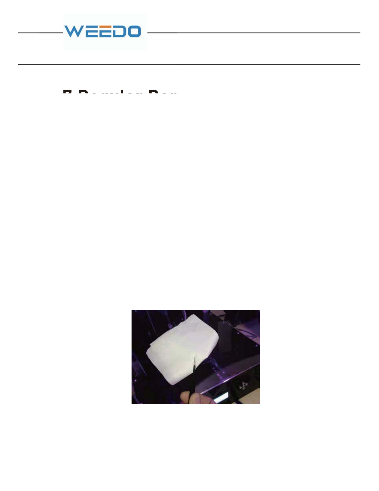
7.1. Printer Regular Maintenance Guide
The regular maintenance mainly contains: clean printer nozzle, replace the printer
platform sticker (1), printer platform regular check and leveling, replace air
filtration core, optical shaft and screw rod maintenance and others.
7.1.1. Cleaning Printing Nozzle
In the process of 3D printing, the part of consumable debris and dust particles is
likely to accumulate around the printing nozzle. As time goes on, these
accumulative materials can lead to that printing precision becomes poor or nozzle
is block and others. Therefore, before printing for each time, it needs to observe
whether the nozzle is blocked and perform the cleaning.
Maintenance method: The printing nozzle is usually cleaned by tweezers (10), and
the impurities around nozzle are wiped out by the cleaning cloth.
7.Regular Repair and Maintenance
3D Printer needs to perform the regular maintenance, as well as some daily
maintenance, in order to ensure the printer can maintain the high performance to
run stably.
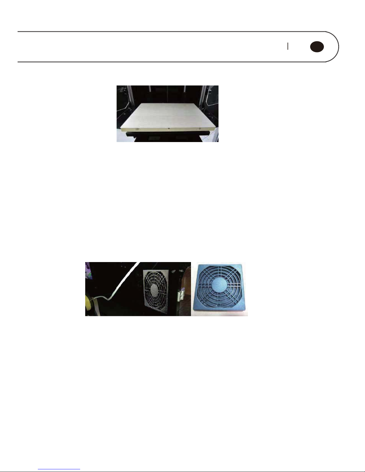
7.1.2. Replacing Printer Platform Sticker (1)
Check whether the printer sticker (1) surface is worn and uneven on the printing
platform, if sticker (1) is worn, it must be replaced, and avoid the model falling from
the platform when printing.
Maintenance method: firstly find out a roll of tape sticker (1) presented in
accompany printer on the accessories box.
Page 43
41 42
GB
Tear out tape sticker (1) on the printing platform from the bottom of left side, strip
slowly, don't leave any residuals, and then paste the new stickers (1).
Note that it doesn't leave gap between the stickers (1).
7.1.3. Replacing Air Filtration Core Components
The air filtration core components are suggested to be replaced after use 500
hours, otherwise it would lead to dust filtration effect greatly reduced.
Maintenance Method:
Firstly, use strength to take out the fan cover board entirety at the right side of
printer, and then find out one filtration core component cover board from the list
box in accompany with printer and install it directly.
7.1.4. Printing Platform Regular Check and Leveling
It is very important to perform the regular check and leveling on the printing
platform, and the level of printing platform would play severe impact the model’s
molding.
Leveling Method:
Nozzle gap adjustment:
Press “Level build plate” in the “Adjust” menu, the printer will automatically level the
build plate. Please operate according to the screen tips and keep the build plate in
rising status until hearing the sounds, it means the leveling operation is
finished.Press the return button to the previous menu.
Page 44
7.1.5. X / Y offset adjustment of the right and left Nozzle
For
dual-extruder printer,when you change nozzle you have to do the things
bellow:
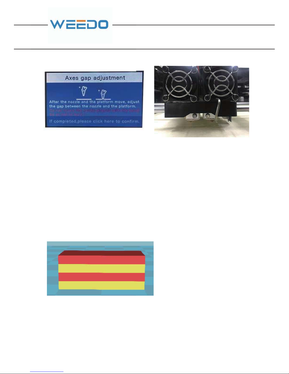
Print the rectangular test block file dualtest.x3g on the SD card, and the file model
is a four-layer rectangular block as below
When we want to change a new nozzle,firstly, Press “Level build plate” in the “Adjust”
menu.DO with what the machine tell you to do,after we finished the Level build plate.
We need to press “Axes gap adjustment” ,then the nozzle will move to the plate,at this
time we use Hex wrench 2.0mm(11) to adjust the height of the nozzle make sure the
nozzle on the surface of the plate.When all of these things done.We can print.
*2
Among them, the first and the third layer from the bottom (the yellow part ) will be
printed by the left Nozzle; the second and the fourth layer (the red part) will be printed
by the right Nozzle.
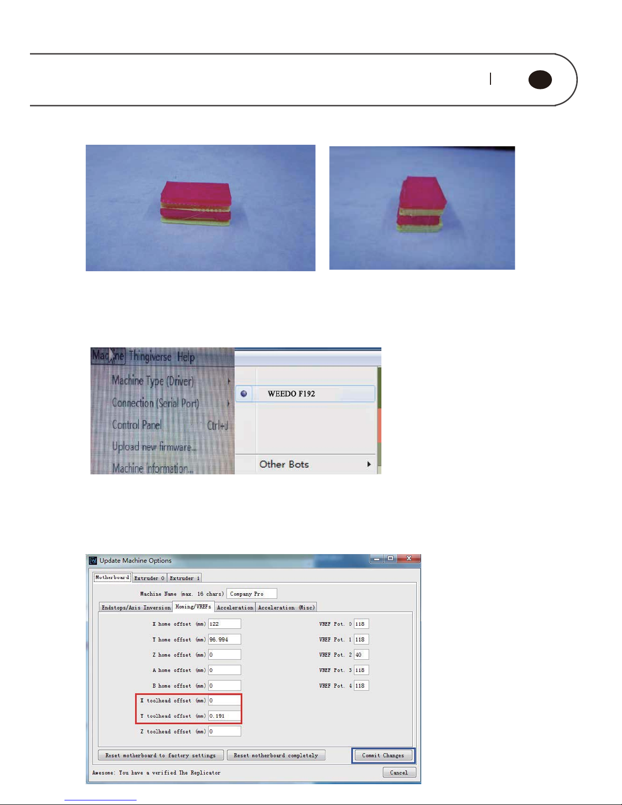
If there are separated parts printed by the left and right Nozzles in the printed block,
which means that there is a deviation on the red and yellow part in the X, Y direction (
as shown below), then you need to conduct Nozzle offset adjustment .
Page 45
43 44
GB
Offset adjustment steps:
Open the ReplicatorG printing software, select "Machine " → " Machine Type ( Driver
) " on the menu bar, then select a machine that matches your model.
Connect the printer to the ReplicatorG printing software, select "Machine " → "
Onboard Preferences" on the menu bar, and enter the interface for printer parameter
setting. Select "Homing / VREFs" option and adjust X toolhead offset and Y toolhead
offset value.
Page 46
Page 47
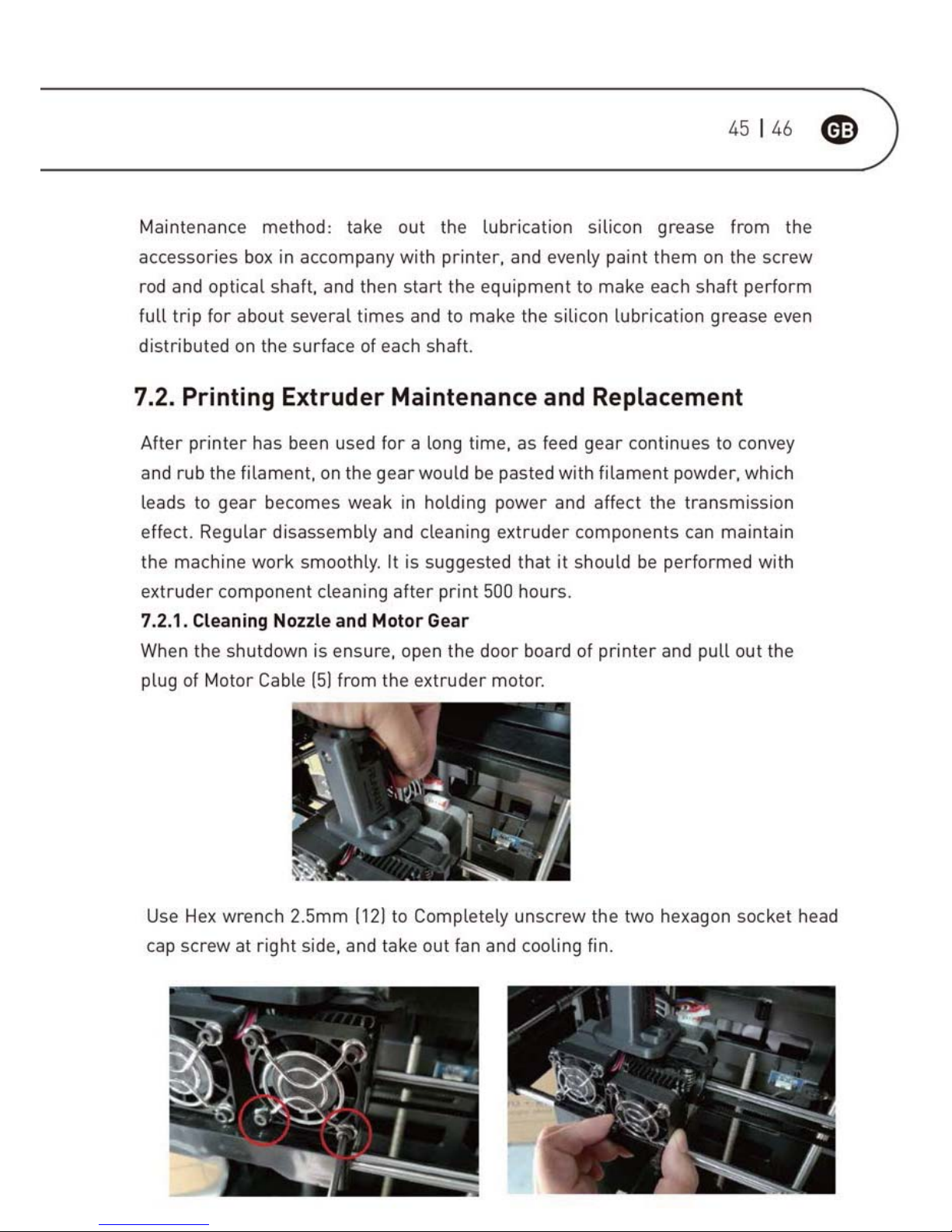
Page 48
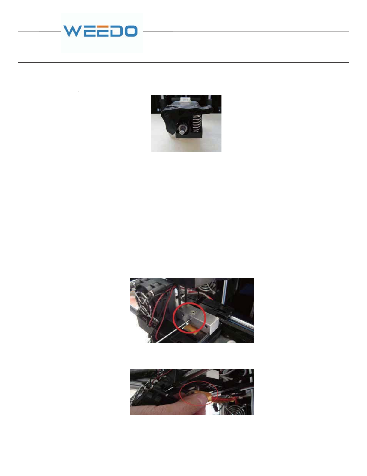
Then, take out the whole motor and feed gear from right back side
The filament debris on the motor gear is performed with cleaning by tweezers (8) ,
and installed is performed according reverse procedures after cleaning.
Note: Finally plug in the motor connection line.
7.2.2. Replacing Printing Nozzle
When the operation is inappropriate or the filament materials is not selected
properly, they would cause nozzle blockage. In the necessary cases, it needs to
perform the nozzle replacement.
Dis-assembly Procedure:
Firstly, take out the motor gear components, the specific procedure can be referred
to chapter 7.2.1 of “Cleaning Nozzle and Motor Gear”.
Use Hex wrench 2mm (11) to tighten the screw fixed nozzle throat.
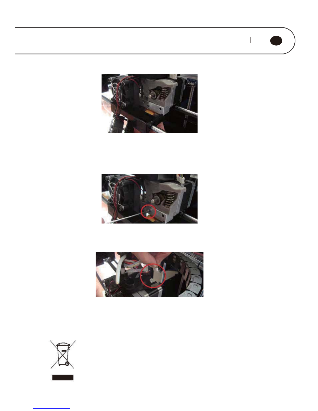
Take out the whole component of nozzle from the bottom and pull out the
connecting line plug of nozzle.
The process of nozzle dis-assembly is over.
The Installation Process of New Nozzle Components:
Firstly, place the motor gear a component at the original position, which is used to
determine the length that nozzle throat stretches out above the aluminum block.
Then, take out the whole motor an
d
Page 49
47 48
GB
The throat pipe part of new nozzle is inserted into the aluminum block from the
bottom, the top of throat pipe closely contacts with the bottom of motor gear (note:
Motor position can’t be moved); and then Use Hex wrench 2mm (11) to screw down
the screw of fixed throat pipe.
For next, well install the fan, cooling fin and motor, Use Hex wrench 2.5mm (12) to
screw down the two hexagon socket head cap screw on the top, and finally plug in
the motor cable (5)
The whole process is over. After the nozzle is replaced, it can start printing model
only after the printer platform is re-calibrated.
7.2.3. Appliance’s end of life
The crossed-out wheeled bin symbol indicates that the item should
be disposed of separately from household waste. The item should
be handed in for recycling in accordance with local environmental
regulations for waste disposal. By separating a marked item from
household waste, you will help reduce the volume of waste sent to
incinerators or land-fill and minimize any potential negative
impact on human health and the environment.
Page 50
8.Frequently Asked Questions
and Troubleshooting (FAQ)
Should the filament replacement operation be run for operating the printer
each time?
The filament replacement operation should not be run for startup of printer
each time, but only be used in the filament replacement.
After the model is completed with printing, can it be taken down the model
by hand immediately?
Please do not get model by hand immediately, please wait the model
cooling for a moment, and gently shovel away the model by scraper (13) ; be
attention not to shovel the tape sticker (1) on the printing platform to bad.
Power indicator light is bad, how do we do?
Please check whether the power cable (4) is well connected with printer,
and the power switch on the printer is “1”, and the power button has already
been opened.
The model bottom does not stick platform, or model is moved, how do we
deal?
Please check whether it is correct for temperature set for printing platform,
and whether the printing platform has already reached the setting
temperature.
If the printing platform temperature is correct, please check whether the
printing platform (printing platform) is flat, adjust the printing platform.
Page 51
49 50
GB
5.The printing nozzle is blocked and unable to feed filament material, how
do we deal?
Please check whether the filament material is used up on the reel support,
1) The filament materials are used up, which shows the filament material is
left in the printer nozzle. Please use Hex wrench 2.5mm (12) disassemble
the fan above the printing nozzle, and use Hex wrench 2mm (11) to Loosen
the screw which fixed nozzle ,take off the printing nozzle and then heat the
printer nozzle to 230°C, use tweezers (8) to pull out the filament section
carefully. Shut down the printer and re-install it after the printing nozzle
cools down.
2) The filament materials aren’t used up, which shows the printing nozzle is
blocked. Please use Hex wrench 2.5mm (12) disassemble the fan on the top
of printing nozzle, and check whether the feed gear is twined with filaments.
If there is twined filament, it cuts off the filament at the top of aluminum
block ,use Hex wrench 2mm (11) to Loosen the screw which fixed nozzle,
and removes the printing nozzle, and then heat the printing nozzle to 230°C,
Use tweezers (8) to pull out the filament section. Shut down the printer,
Unplug Motor Cable (5) cord and then take out the whole motor and feed
gear, clean the filament debris in the feed gear by tweezers (8) , and
installed is performed according reverse procedures after cleaning. If there
is no twined filament, please heat the printer nozzle to 230°C, press down
the handle of nozzle, manually input filament materials, slightly use
strength to push filament materials down, push out the filaments left in the
printing nozzle, and then take out filament materials manually, repeat
several times, until the printing nozzle is completely cleaned.
Please be carefully to dredge the printing nozzle, in order to avoid scalding.
If the printing nozzle can’t be dredged, please contact our company for
replacement of printing nozzle. The printing nozzle is replaced; it can start
to work until the printing platform is needed to adjust to flat once again.
Unable to generate Gcode Tip?
Python software has something wrong with the Installation. If user only
installed ReplicatorG , Please Uninstall the software , and install Python
Page 52

,and then re-install ReplicatorG; If user has installed Python and
ReplicatorG, Please Uninstall original Python and ReplicatorG, and
re-install them. The default installation path is C drive.
After installing the print software driver, connect Print cable (3) and point
out not connect to the printer?
First make sure the printer is on, the USB connection is already seated, the
printer USB port is correct, and check whether has clicked "connect the
printer" option on the software, or failing that, you can restart your
computer to try again.
If still cannot connect, consider whether the print driver is not installed well,
or you can re-install the print software to try again
After installing the printing software, there will be an error message in the
screen:
Could not create the java virtual machine.
One possibility: The system configuration issues cause problems of java
virtual machine, the front desk software report errors without starting.
Allow customers to enter the C drive ReplicatorG installation directory, run
ReplicatorGxp .EXE and try.
One possibility: problems of the virtual memory settings. It is possible that
the consumer has set up a 5-10g virtual memory and beyond the maximum
of software identification. Selecting automatically assigned in system
Settings:
Using Netfabb software to view the model dimensions, check whether there
is a error in the model ,check whether the model there is a problem and
how to fix the problem model.
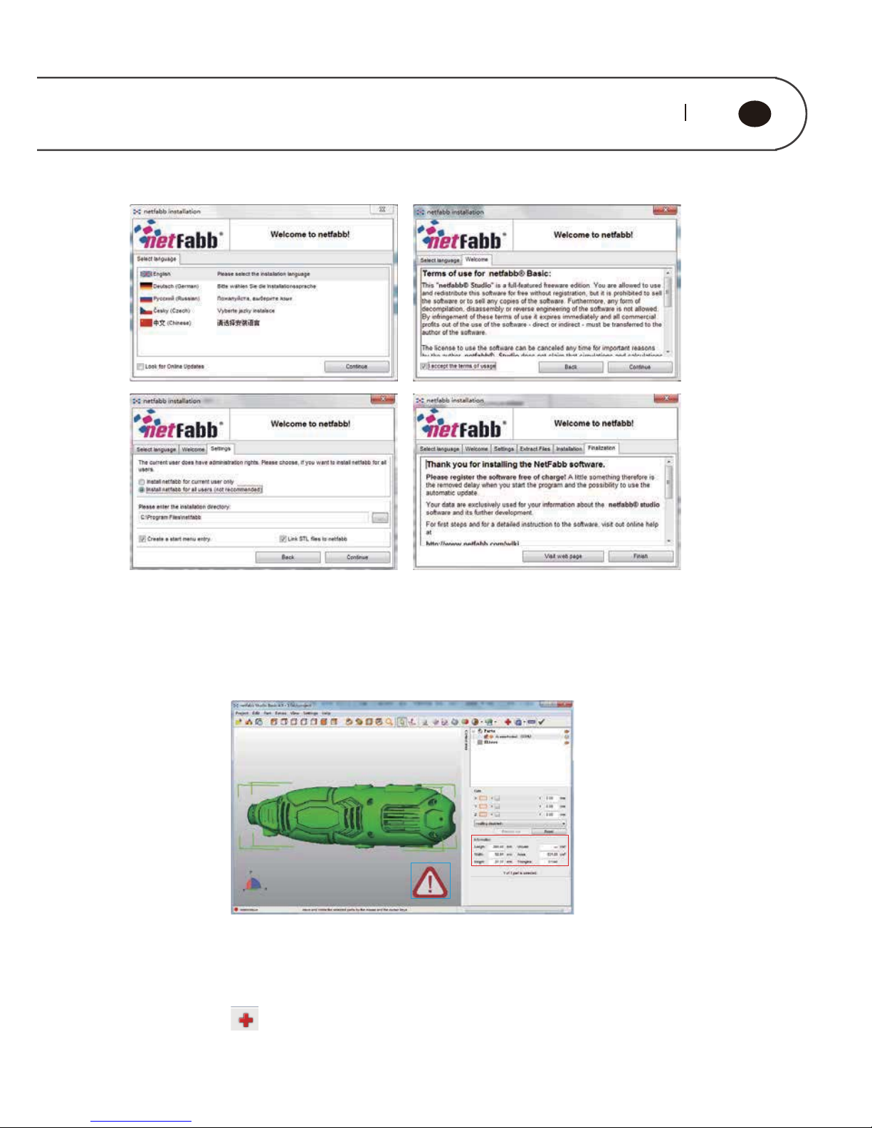
Run the software installation package, Netfabb Installer-offline, in the
installation wizard window, click “Continue” to install the software. After
installation is complete, click "Finish" to exit.
Page 53
51 52
GB
The figure below displays a standard interface of netfabb studio
Red box is model size.
Before using ReplicatorG for model slice, you can view the model size by Netfabb.
When model size exceeds the maximum print size, it is unable for model sliced.
Blue box is these is a error for model. If the interface displays an exclamation mark
at the bottom right, it means that the model error. When the STL model is abnormal
or has error, it will not print or print out physical distortion occurs. Using Netfabb
can easily repair STL model error. Click on the menu bar. Model errors sections
in yellow lines represent. Click “Automatic repair “- “Default repair” -”Execute” to
repair option to use the default.
Page 54
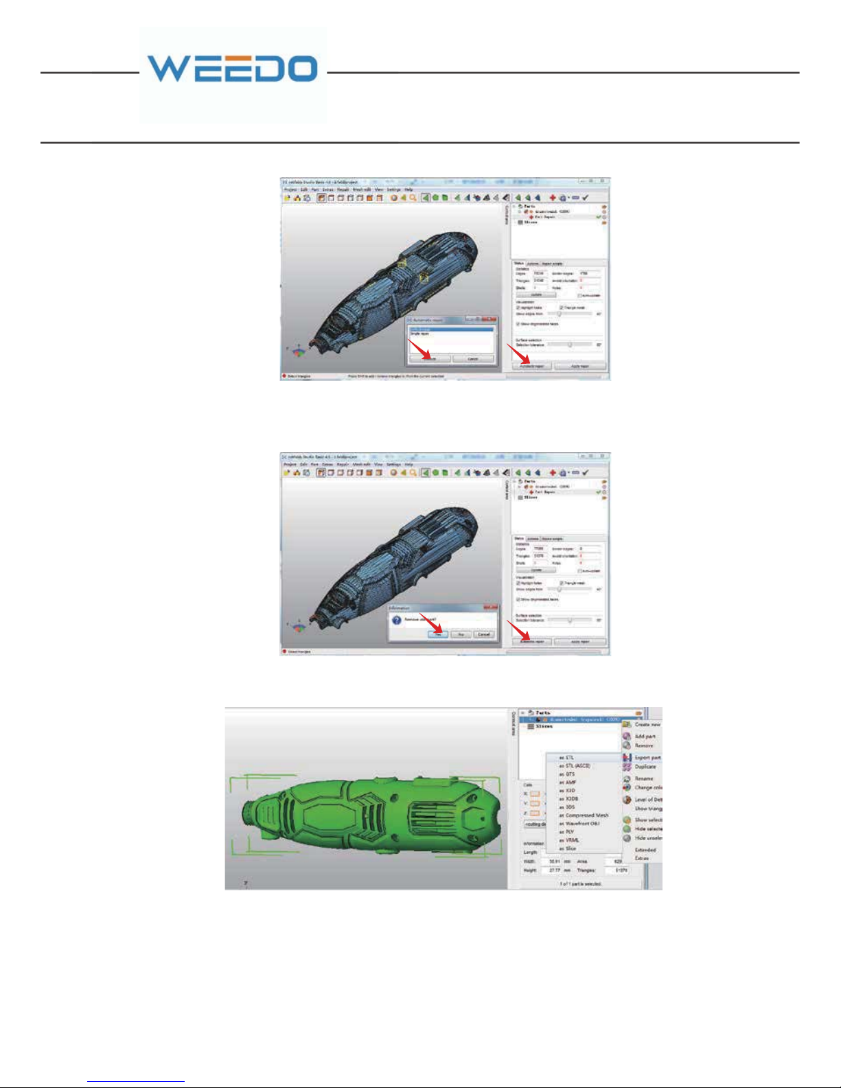
Model repair is successful, the model of the yellow lines disappear. Click “Apply
repair” after repair model will replace the original model. Click “Yes”
Right click on the model in the model name list. Export the model to STL file.
Page 55
53 54
GB
WARRANTY CARD
Firstname Lastname
Street/No. Telephone
Postal Code City Mobil
Item-nu mber Barcode (EAN)
Warranty
(please mark with a cross)
Salesreceipt number/Date
(Please also attach a copy ofthe salesreceipt)
Yes No
Purchased at WEEDO store
Which error occurred (please specify)
(Please describe the problem or malfunction of your device as accurately as
possible. This allows us to process your complaint more quickly and efficiently. An
imprecise description with terms like "device is not working" or "broken device" can
delay the process considerably).
Page 56
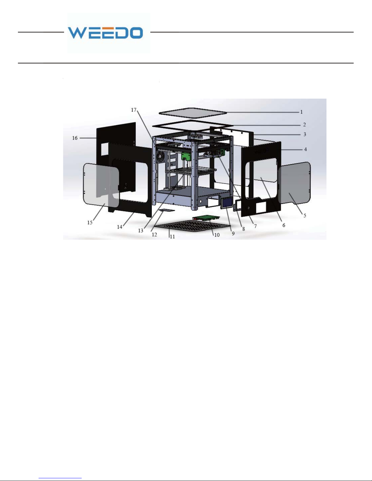
TECHNICAL DRAWING
SPARE PARTS LIST
1. Top decorative door
2. Top decorative panel
3. Right decorative panel
4. Front decorative panel
5. Front decorative door
6. Right decorative door
7. Nozzle Assemlbe part
8. Touch Screen decorative panel
9. Touch Screen
10.Motherboard
11. Cover
12. Relay module
13. Prnting plate
14. Left decorative panel
15. Left decorative door
16.Rear decorative panel
17. Air filter fan
TECHNICAL DRAWIN
G
Page 57
55 56
GB
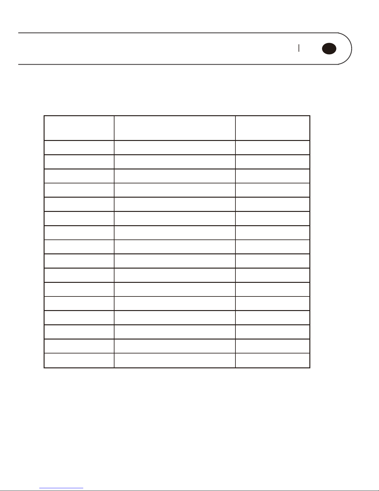
NO. Fitting Quantity
1
2
3
4
5
6
7
8
9
10
11
12
13
14
15
16
1
1
1
1
1
1
1
1
1
1
1
1
1
1
1
1
Tape sticker
Reel support
Print cable
Power Cable
SD Card
SD Reader
Knife
Tweezers
Metal Wrench
Hex wrench 1.5mm
Hex wrench 2.0mm
Hex wrench 2.5mm
Plastic Scraper
X Moter line
X Switch line
Z Switch
 Loading...