

Page 1

USER MANUAL
ENGLISH (EU) – 01/03/2018 – ISSUE 2
Page 2

M1200 – User manual – English (EU) – 01/03/2018 - ISSUE 2
Page 3

M1200 – User manual – English (EU) – 01/03/2018 - ISSUE 2
3
TABLE OF CONTENTS
1. INTRODUCTION ____________________ 4
2. IMPORTANT INFORMATION ___________ 4
3. PRODUCT DESCRIPTION _____________ 5
4. FOAMSTREAM® ___________________ 11
4.1 HOW FOAMSTREAM® KILLS WEEDS ______________________ 11
4.2 INDICATORS ____________________________________________ 11
4.3 CAUTION – POISONOUS WEEDS ____________________________ 12
4.4 THE EFFECT OF THE SYSTEM ON PLANTS _____________________ 12
5. PRE-START CHECKS ________________ 14
6. START PROCEDURE ________________ 15
7. SCREEN AND PLC NAVIGATION _______ 18
8. USING THE M1200 _________________ 19
9. FOAMSTREAM® APPLICATION (KILLING
WEEDS) ____________________________ 21
9.1 HOSE REEL _____________________________________________ 21
9.2 SPEED _________________________________________________ 21
9.3 USE OF THE LANCE _______________________________________ 21
9.4 TREATMENT OF THICK WEEDS ______________________________ 22
9.5 TREATMENT _____________________________________________ 22
9.6 CONFIRMATION OF TREATMENT ____________________________ 22
9.7 CORRECT POSTURE_______________________________________ 22
10. SHUT-DOWN PROCEDURE _________ 23
11. BASIC FAULT FINDING ___________ 24
12. SERVICE CHECKS AND INTERVALS _ 29
13. LOADING AND HANDLING ________ 30
14. SCHEMATICS ___________________ 31
15. WARRANTY ____________________ 34
16. PRODUCT CERTIFICATION ________ 36
Page 4

M1200 – User manual – English (EU) – 01/03/2018 - ISSUE 2
4
1. Introduction
Thank you for purchasing the Weedingtech M1200!
IT IS IMPORTANT THAT ALL OPERATORS READ AND
UNDERSTAND THESE INSTRUCTIONS BEFORE USING
THE MACHINE
Having read these instructions, the operator will:
• Understand how the M1200 works
• Identify key components in the M1200
• Know how to carry out pre-start and start-up
procedures
• Observe safe operating practices
• Be able to effectively operate the M1200
• Be able to shut down and clean the M1200
• Be able to perform basic maintenance and
troubleshooting tasks
PLEASE KEEP THESE INSTRUCTIONS IN A SAFE PLACE
FOR FUTURE REFERENCE
2. Important information
The following PPE (Personal Protective Equipment) are
recommended when operating the M1200:
• Eye protection is required when handling
Foamstream® concentrate
• Gloves are required as the lance assembly will get hot
• Safety Footwear suitable for working in the areas
concerned is recommended
• No specific protective clothing is required, although
use of overalls and a HI-Viz vest is suggested as best
practice.
IT IS THE RESPONSIBILITY OF THE OPERATOR TO WEAR
APPROPRIATE PPE
Never operate the machine without checking that there are
adequate supplies of clean diesel, clean water and clean
Foamstream® concentrate in the appropriate tanks.
The M1200 produces VERY HOT water. This can cause
serious burns and injury if used incorrectly.
Never point the lance at people or animals as this machine
operates at high temperature and low pressure.
All personnel operating a M1200 machine must be deemed
competent to do so and must be adequately trained. A copy
of the training record is available on demand.
Always check the M1200 for any damage before use.
Damaged cables, hoses or connections must be reported
immediately, and the machine taken out of use until repairs
have been completed.
Use only genuine Weedingtech spare parts and
Foamstream® consumables. This will ensure the best
performance of your machine and maintain the warranty of
the unit.
The M1200 must never be modified, safety interlocks
bypassed or settings adjusted (unless specified in these
guidance notes) without Weedingtech’s written consent.
Ensure that the M1200 is placed in an area where there is
adequate ventilation when in use.
Page 5
M1200 – User manual – English (EU) – 01/03/2018 - ISSUE 2
5
Ensure that the consumable liquid (foam concentrate) is not
subject to temperatures below 5 degrees centigrade at any
time.
Ensure that both the M1200 and its water tank are securely
attached to the transport vehicle. It is the responsibility of
the vehicle driver to ensure that any load is secure and that
any payload restrictions are observed you can refer to
section 13 for more information on transport.
NEVER OPERATE THE M1200 WITHOUT FOAMSTREAM®
CONCENTRATE
3. Product description
The M1200 weed control unit consists of:
• Foamstream®
• Water tank (780 litres)
• Hose reel (30 metres)
• Lance
The M1200 houses a diesel-powered boiler, a dieselpowered generator, a logic controller (PLC), a piston pump,
a 52 litres diesel tank, and a 22 litres Foamstream®
concentrate tank.
When the water reaches 95 degrees centigrade, a valve
opens allowing water to flow from the lance (12 lpm @ 12
bar) and a venturi mixer opens to allow Foamstream®
concentrate to be injected at a ratio of 99.5 parts water to
0.5 parts concentrate. Air is added to the water and
Foamstream® mix as it exits the lance to create the foam.
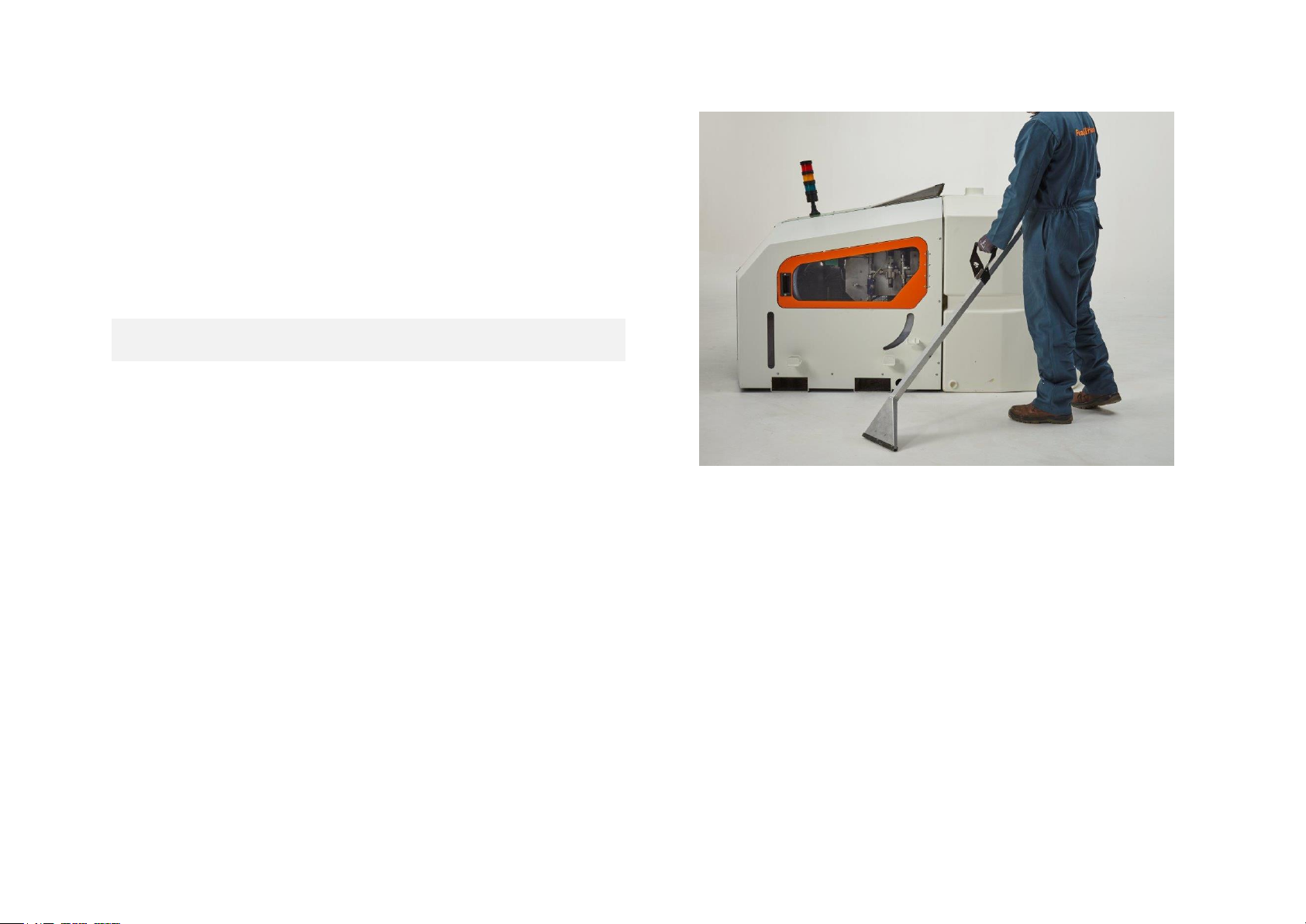
Figure 1 - M1200 (operator not included)
When the machine is switched on and operational, water is
pumped at 12 litres per minute and passes through the
boiler to be heated up to a minimum of 95 degrees
centigrade.
The M1200 has been designed to require no manual input or
adjustment. The PLC monitors the system pressure,
temperature and flow rate to ensure optimum performance
of the unit.
A pressure relief valve and over-temperature sensor ensure
that internal pressure and temperature will not exceed 35
bar or 120 degrees centigrade in the event of a system fault.
Operation of the M1200 is via the user interface at the front
of the unit (see section 6 for details).
Page 6

M1200 – User manual – English (EU) – 01/03/2018 - ISSUE 2
6
Filters are fitted to the diesel, water and foam systems to
ensure supplies are kept clean and free from debris. These
needs to be checked daily (see section 5).
Access panels to the right and left-hand side of the M1200
can be opened with a key to allow access to filters, pipes
and hydraulic components. These panels can be easily
removed for maintenance purposes. Access to the
electronics is via a door on the front of the M1200 which can
be opened by a key.
The water tank (780 litres) can be either separate from the
unit or attached to it by bolts on the frame. There are two
hydraulic connections (water supply, water return), one
electrical connection (water sensor) and 13 bolts when the
tank is attached to the unit.
An automatic hose reel is located inside the unit to allow the
30 metres hose to be stowed safely when the M1200 is not
in use. The hose comes off the top of the reel and is
connected to the lance via a connector.
M1200
HEIGHT (mm)
1200
WIDTH (mm)
1206
DEPTH (mm)
1250 or 2120 (with tank)
WEIGHT (kg)
326 EMPTY, 400 FULL
WATER
780 LITRES
FUEL
DIESEL – 52 LITRES
FOAMSTREAM
FOAMSTREAM – 22 LITRES
GENERATOR OIL
1.2 LITRES SAE 5W40
PUMP OIL
0.3 LITRES SAE 5W40
FLOW RATE
12 LITRES PER MINUTE
OPERATING
PRESSURE
30 BAR ON HEAT UP, 12 BAR
TRIGGER OPEN
OPERATING
TEMPERATURE
95 – 110 °C
PRESSURE
RELIEF VALVE
35 BAR
OVER
TEMPERATURE
CUT-OUT
125 °C
GENERATOR
4.5 kVA – DIESEL POWERED
BOILER
95 kWh – DIESEL POWERED
Page 7
M1200 – User manual – English (EU) – 01/03/2018 - ISSUE 2
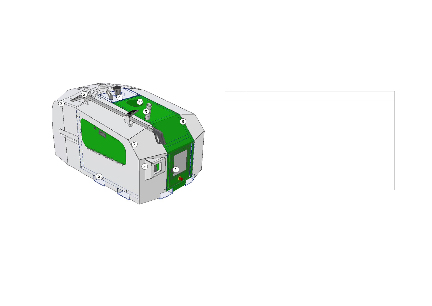
Figure 2 – Perspective view of the M1200
Num.
Description
1
Control panel
2
Lance
3
Water tank
4
Exhaust hood
5
Hose reel orifice
6
Forks entry
7
Left cover panel
8
Right cover panel
9
Traffic lights
10
Hot air extraction fan
Page 8
M1200 – User manual – English (EU) – 01/03/2018 - ISSUE 2
8
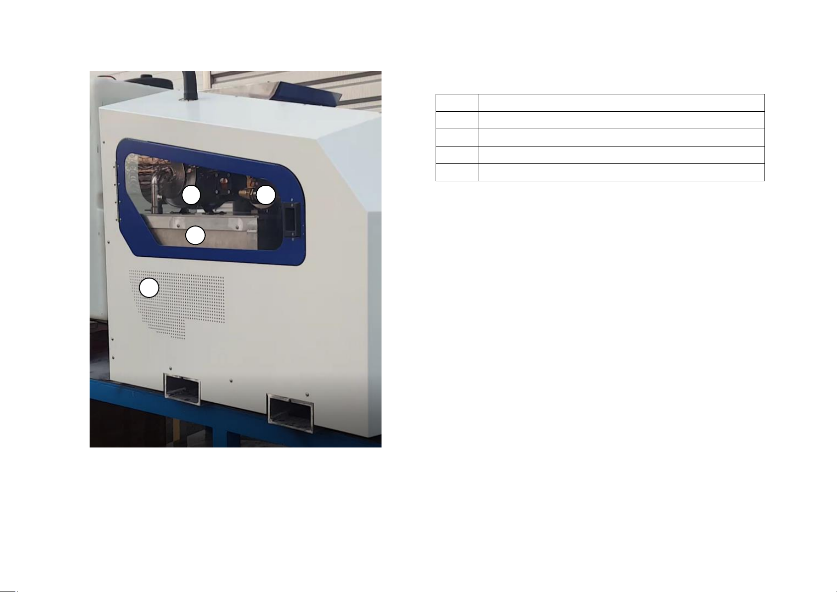
Figure 3 - Left inside view of the M1200
Num.
Description
1
Diesel particulates filter (Optional extra)
2
Water pump
3
Diesel generator vent (CAUTION HOT)
4
Diesel generator (CAUTION HOT)
1 2
3
4
Page 9
M1200 – User manual – English (EU) – 01/03/2018 - ISSUE 2
9
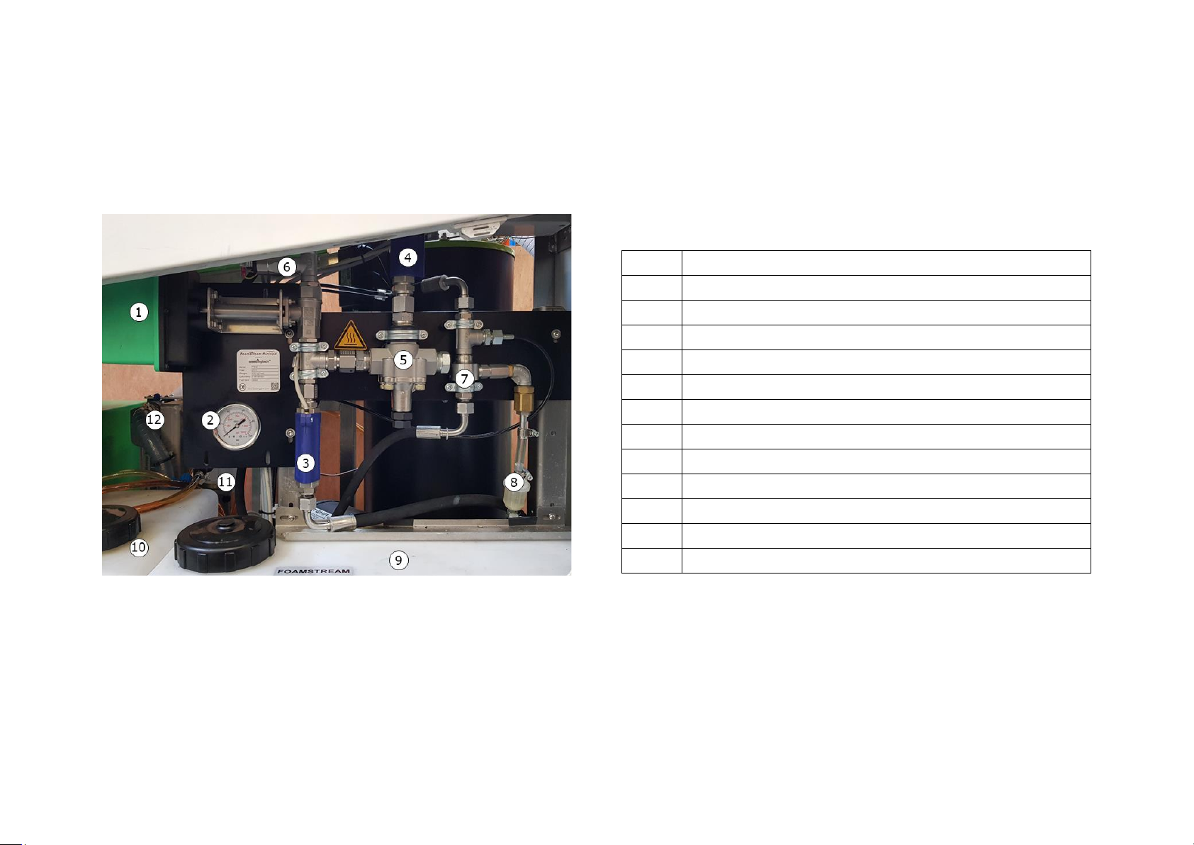
Figure 4 - Right view of the inside of the M1200
um.
Description
1
Lance solenoid valve
2
Pressure gauge
3
Main flow switch
4
Return to tank flow switch
5
Pressure relief valve (PRV)
6
Lance pressure switch
7
Venturi
8
Foam filter
9
Foam tank
10
Diesel tank
11
Boiler diesel filter
12
Water filter
Page 10
M1200 – User manual – English (EU) – 01/03/2018 - ISSUE 2
10
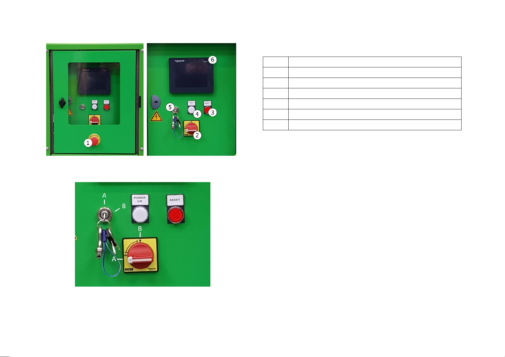
Figure 5 - Closed control box (left) open (right)
Figure 6 – Detail of the switches on the front panel
Num.
Description
1
Emergency stop
2
Main contact switch
3
Boiler reset button
4
Power light
5
Diesel generator start key
6
PLC screen (touch screen)
Page 11
M1200 – User manual – English (EU) – 01/03/2018 - ISSUE 2
4. FOAMSTREAM®
4.1 How FOAMSTREAM® kills weeds
Foamstream® uses heat to kill weeds. Water is heated to
near boiling point and then mixed with the Foamstream®
concentrate to produce foam before being applied. The foam
blanket ensures that the heat is held on the plant so that the
weeds experience hot, killing temperatures for a few
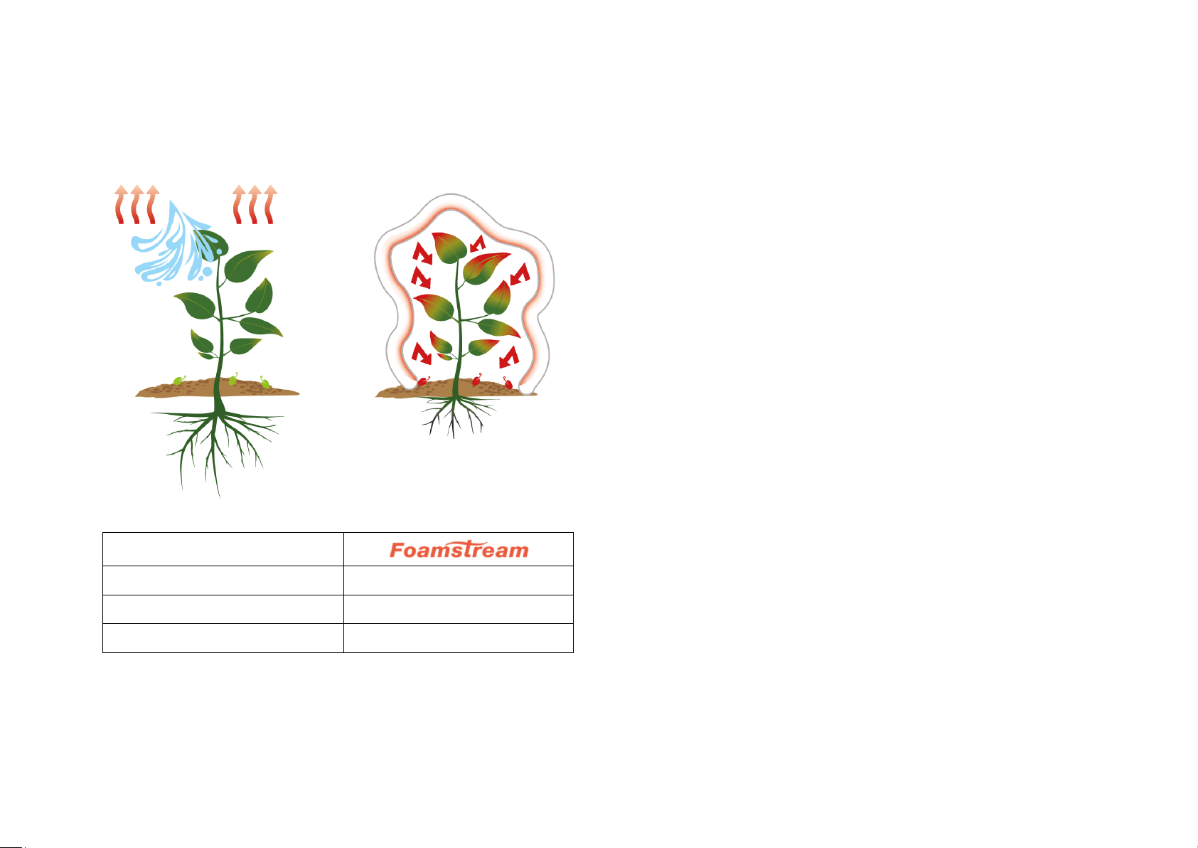
seconds. Figure 10 below explains and compares the process
to hot water and steam.
4.2 Indicators
The lances can apply large volumes of water and foam and
can be used to kill larger weeds. Foam cover, and hence heat
retention on weeds, is easier to achieve on prostrate plants
that are near the ground. Tall plants should be trodden
down either by foot or by using the lance outlet, to aid foam
cover and heat retention.
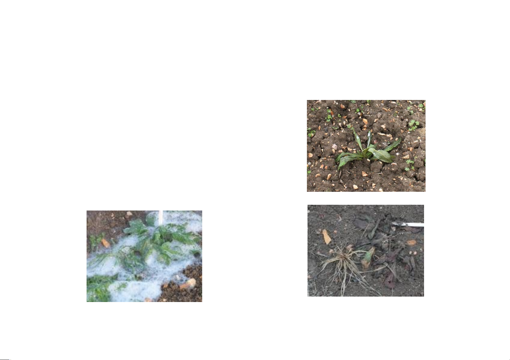
Figure 7 - Foamstream during treatment
Immediately after treatment, weeds will go dark green and
limp. This indicates that the machine is operating properly.
The weeds will die; this becomes more obvious within the
next one to seven days (depending on species and weather).
If weeds fail to go limp, temperatures may be too low or
forward speed to high.
Figure 8 - Weed immediately after treatment with Foamstream
Figure 9 - Weed 24 hours after treatment with Foamstream
Page 12
M1200 – User manual – English (EU) – 01/03/2018 - ISSUE 2
12
If weeds go brown immediately after treatment, this could
indicate that forward speed is too slow and excessive heat
is being applied.
Figure 10 - Foamstream's triple action
Steam / Hot Water
Kills the leaves
Kills weeds
No effects on seeds
Sterilises seeds
Very weak effect on roots
Damages the root
In general, annual weeds are easier to kill than biennial or
perennial ones. Weed species that originate from desert or
semi-arid regions are more heat tolerant and will need a
slightly prolonged treatment period compared to other
species.
Biennial or perennial weeds usually have parts protected
against heat (especially regenerative parts under the soil,
the Rhizome). Foamstream is a contact application, it will
kill foliage but many perennial and biennial plants will
regenerate. The number of repeat treatments required to
completely kill weeds depends on the species and their size.
4.3 Caution – poisonous weeds
Some poisonous weeds, such as common ragweed (Senecio
jacobaea) may still be attractive to animals after treatment
with Foamstream. When treating any area where animals
are likely to graze after treatment with Foamstream, check
for the presence of such potentially toxic weeds and remove
them or keep out of reach of animals that are at risk.
4.4 The effect of the system on plants
The M1200 has been designed to operate in an urban
environment and control weed growth on both hard surfaces
and cultivated land. These weeds may be in, at, or around
kerbs and channels, footpath edges, driveways, boundaries,
obstacles etc.
Within these environments there are various plant species
that need to be controlled. These species may vary in type
and growth patterns depending on the specific geographic
location.
The system, through its unique operation, delivers a plant
kill based on thermal activity penetrating and breaking down
the cell structure of the plant.
With varying plants in the target area it is important for the
operator have some knowledge of the weed types, sizes and
Page 13

M1200 – User manual – English (EU) – 01/03/2018 - ISSUE 2
13
ages that they are treating, as this impacts on the speed of
operation to deliver an effective kill.
For maximum efficacy, it is important that all weeds in the
target area are in contact with the hot foam. Either flatten
tall weeds i.e. by treading or use of the lance or ensure that
the stems are ‘ring barked’ (completely surrounded by a
blanket of foam). The density of the plants and foliage is a
very important aspect for the operator to be aware of, as
this also impacts on the speed of operation. It should be
noted:
• As the height and/or density of the target plants
increases, the speed of operation will be slower.
• In a situation where regular treatment of the area is
part of a maintenance programme the weeds will
generally be easier to treat as regrowth should be
reduced.
• Regular treatment also allows increased speed of
operation, as the volume of target plants to kill will be
minimised on each maintenance cycle.
Page 14

M1200 – User manual – English (EU) – 01/03/2018 - ISSUE 2
14
5. Pre-start checks
THESE CHECKS MUST BE COMPLETED BEFORE EACH
START OF THE M1200. ANY FAULTS MUST BE RECTIFIED
BEFORE THE M1200 IS SWITCHED ON.
✓ The M1200 water tank is securely attached to the
transport vehicle
✓ The M1200 is in good condition and panels are
closed
✓ There are no signs of leaks from any pipe or
connection
✓ Pipe routes are clear of sharp edges and hot
surfaces
✓ Air intakes are clear of debris
✓ Generator and boiler exhaust are secure and clear of
debris and obstruction
✓ Water tank is full of clean water
✓ Water filter is clean and free from debris
✓ Water feed valve is connected and in the ‘on’ (inline)
position
✓ The water return pipe and water level sensor is
connected
✓ Air has been bled from water system (see section 7)
✓ Fuel tank is full of clean diesel fuel (derv or gasoil)
✓ Boiler fuel filter is clean and free from debris
✓ Foamstream® concentrate tank is full of
Foamstream® concentrate
✓ Foamstream® filter is clean and free from debris
✓ The consumable has not been subject to
temperatures below 5°C and frozen or separated
✓ Vent screw on Foamstream® tank filler cap is open
✓ Generator engine oil level is correct
✓ Pump oil level is correct
✓ The lance, hose reel and hose are securely
connected and free from damage
✓ Lance wear pads are not excessively worn
Page 15
M1200 – User manual – English (EU) – 01/03/2018 - ISSUE 2
15
6. Start procedure
✓ Complete pre-start checks (see section 5)
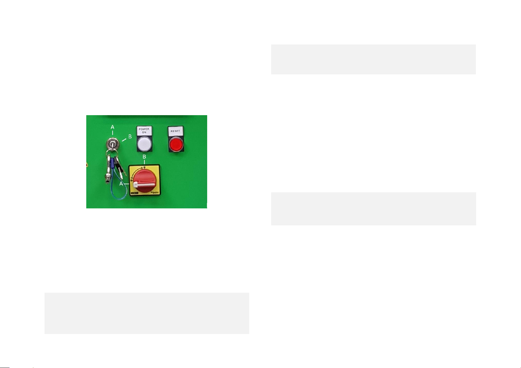
✓ Start the generator by turning the key in a clockwise
direction to position ‘B’, release to position ‘A’ when the
engine starts (see Figure 11)
✓ Turn the isolator switch to position ‘B’ (see Figure 11), the
PLC screen should illuminate (see Figure 12)
Figure 11 - Details of the switches of the front panel
✓ The reset indicator (red light) lights up and ‘FAULT’ will
appear on the top right hand corner of the PLC screen
✓ Press the ‘RESET’ button (red button on the front panel,
see Figure 5), the ‘FAULT’ indicator goes out and you
should see the screen represented in Figure 12
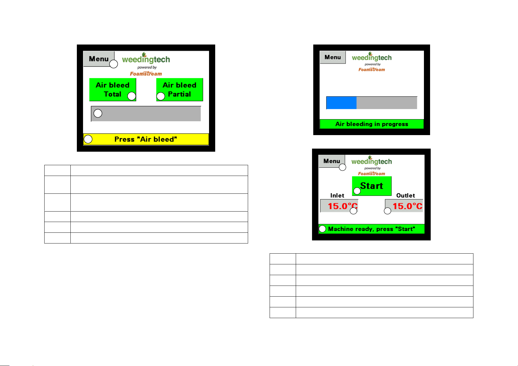
✓ Wait a few seconds before requesting air bleed: buttons
‘1’ or ‘2’ in Figure 12
If you have disconnected the water tank or are starting
for the first time of the day, please use “Air bleed full”
If you just took a break or want to perform an additional
air bleed, please select “Air bleed partial”
When bleeding the machine, the trigger must be
pushed to allow water to flow out of the lance. Failure to
do so will cause the machine to display a fault message.
✓ Once button ‘1’ or ‘2’ is pressed the bleed screen
represented in Figure 13 will appear.
✓ Wait until the purge is completed. A new screen will
appear, represented in Figure 14.
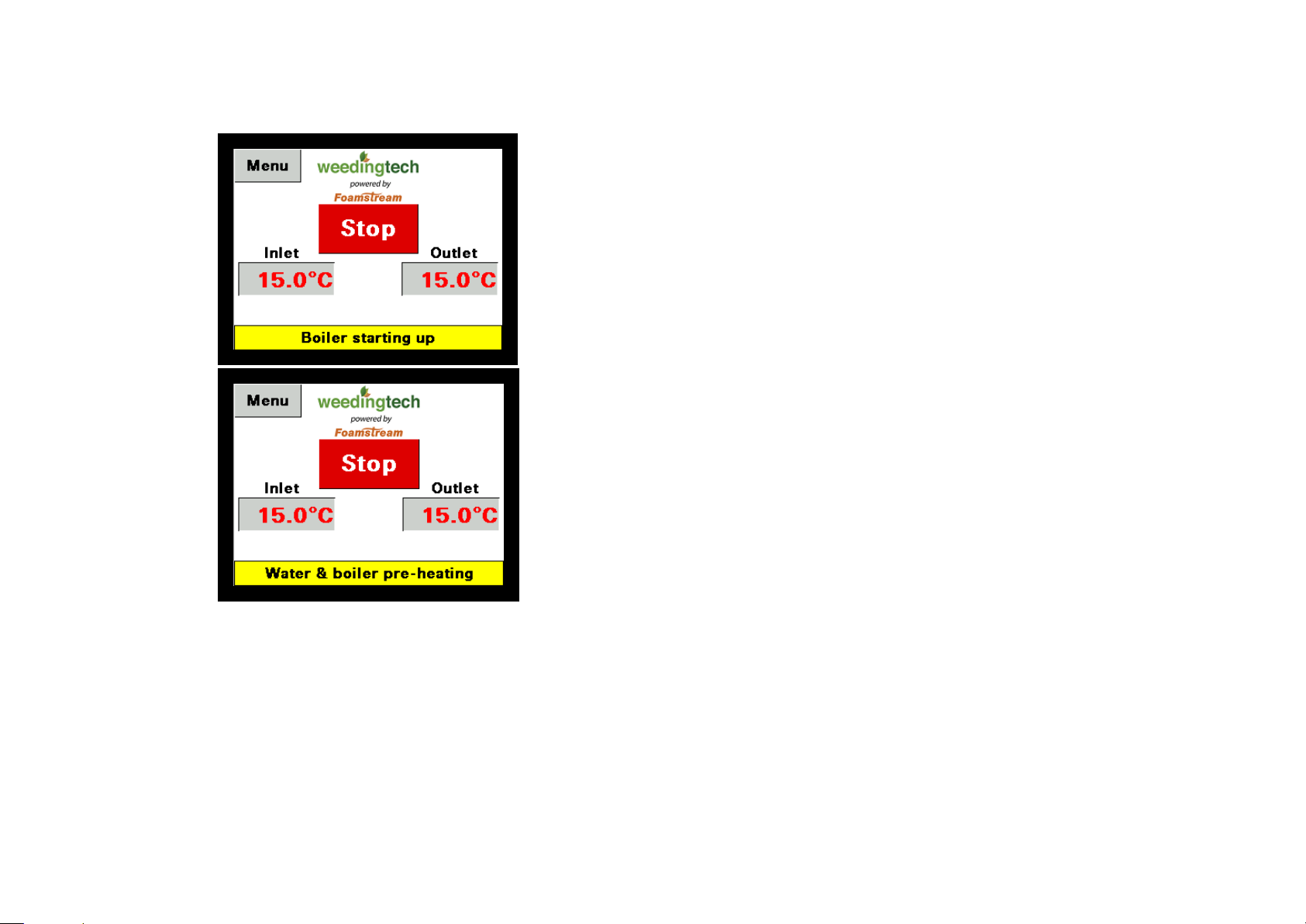
✓ Press ‘START’, the button turns green and the screen
represented on Figure 15 will appear.
✓ The amber ‘HEATER’ light will illuminate and the red
‘FAULT’ button should go out. This indicates that the
boiler has switched on and is heating the water
✓ The green ‘READY’ light will illuminate when the M1200
has reached operating temperature and the system is
ready for use (3 – 5 minutes).
AFTER A COLD NIGHT (BELOW 0 DEGREES CELSIUS),
LET THE GENERATOR RUN FOR 15 MINUTES TO WARM
UP THE MACHINE BEFORE STARTING THE PUMP OR
BLEEDING THE UNIT
Page 16
M1200 – User manual – English (EU) – 01/03/2018 - ISSUE 2
16
Figure 12 - Start-up screen of the PLC
Num.
Description
1
Press this button to purge the M1200 for 30
seconds.
2
Press this button to purge the M1200 for 10
seconds.
3
Indication message.
4
Air bleed status indicator.
5
Menu access
Figure 13 - Bleed screen of the PLC
Figure 14 - Start screen of the PLC
Num.
Description
1
Start button
2
Boiler water input temperature
3
Boiler water output temperature
4
Indication message
5
Menu access
1
2
3
4
5
1
2 3
4
5
Page 17
M1200 – User manual – English (EU) – 01/03/2018 - ISSUE 2
17
Figure 15 - Running screen of the PLC
Page 18
M1200 – User manual – English (EU) – 01/03/2018 - ISSUE 2
18
7. Screen and PLC navigation
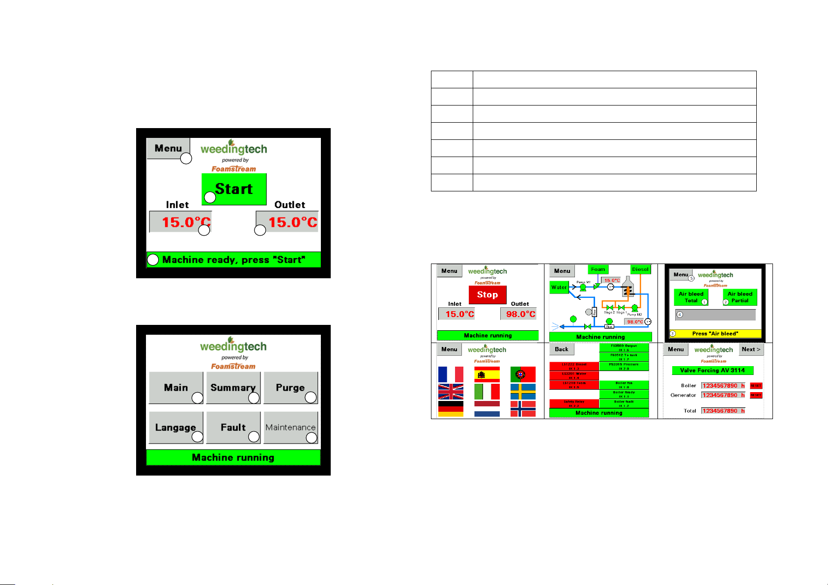
When the M1200 is ready to start, the screen below will
appear (same as Figure 14)
To access the menu, click on the “Menu” button on the top
right hand side of the screen. The screen in will appear.
Figure 16 - Menu screen
Num.
Description
1
Return to main page
2
Go to summary screen
3
Purge
4
Language selection
5
Fault summary panel
6
Maintenance mode
Users have no need to access pages ‘5’ and ‘6’. Page ‘6’ is
restricted by a password. The screens are summarized in
the table below (in the same order as is Figure 16)
1
2 3
4
5
1 2
3
4 5
6
Page 19

M1200 – User manual – English (EU) – 01/03/2018 - ISSUE 2
19
8. Using the M1200
The generator manufacturer does not recommend to use the
generator below 6 degrees Celsius and above 40 degrees
Celsius of ambient temperatures.
The M1200 control panel gives important feedback on the
status of the M1200:
Status
Red
Orange
Green
Ready
Fixed
Fixed
Stand-by
Fixed
Flashing
Boiler active
Fixed
Boiler fault
Fixed
Water tank too hot
Flashing
Level sensor low
Flashing
Boiler overtemp.
Fixed
Flashing
WHITE ‘POWER’ LIGHT
When the generator is on, this light should be illuminated. If
the generator does not start, then the generator plug should
be checked. If the generator breaker position is correct and
the generator does not start the M1200 should be checked
by a competent service engineer.
AMBER ‘HEATER’ LIGHT
If the amber light is illuminated the water is below 96
degrees centigrade and is being heated. If the amber light
does not illuminate, and the red fault light stays on, there
may be a system fault (see below)
GREEN ‘READY’ LIGHT
When this light is illuminated the M1200 is ready for use. If
the green light is not illuminated the water may need
heating (amber light will be on) or there is a system fault
(red fault light will be on, see below).
FLASHING ORANGE LIGHT
If the amber light is flashing the water in the water tank is
too hot. If water in the water tank exceeds 45°C the boiler
will shut down. The water tank will need to be drained and
refilled with cold water, or the level topped up with cold
water.
RED ‘RESET’ LIGHT
The red reset light should switch off when the reset button
is pressed during start up. If the light stays on there is an
electrical fault which needs rectification. The M1200 should
be switched off until the fault has been corrected.
FLASHING RED ‘RESET’ LIGHT
A flashing red reset light indicates a boiler fault. The M1200
must be switched off and checked by a competent service
engineer.
RED ‘FAULT’ LIGHT
The red fault light will illuminate at start up until the green
button is pressed and the amber light illuminates. If the red
light stays on, and the amber light fails to illuminate, the
system may need to be bled to remove air (see section 7).
Page 20

M1200 – User manual – English (EU) – 01/03/2018 - ISSUE 2
20
If the red light fails to switch off after bleeding there is a
system fault. The M1200 should be switched off until the
fault has been corrected by a competent service engineer.
RED ‘FAULT’ AND FLASHING AMBER LIGHT
An illuminated red fault light and flashing amber light
indicates the boiler is too hot. The M1200 should be switched
off and checked by a competent service engineer.
GREEN AND AMBER WITH FLASHING RED ‘FAULT’ LIGHT
A flashing red fault light with illuminated green and amber
lights indicates one of the fluid levels is low (water,
Foamstream® or diesel). The levels should be checked and
filled up accordingly.
THE M1200 SHOULD BE SWITCHED OFF AND CHECKED
BY A COMPETENT SERVICE ENGINEER IF IT DOES NOT
OPERATE AS EXPECTED, OR THE LIGHTS ILLUMINATE IN
A DIFFERENT WAY THAN EXPLAINED.
Page 21

M1200 – User manual – English (EU) – 01/03/2018 - ISSUE 2
21
9. FOAMSTREAM® application (killing
weeds)
To effectively control vegetation with the herbicide-free
Foamstream® system, you must co-ordinate all the different
elements that give a successful result. If one element is not
functioning properly, the desired result will not be achieved.
For effective results the Foamstream® system requires the:
• Correct volume
• Correct temperature
• Correct method
• Correct quantity of foam agent
This section looks at the speed and method of application.
9.1 Hose reel
The M1200 unit is fitted with an automatic hose reel which
contains 30 m of hose as standard. The hose comes off the
top of the reel, and is connected to the lance by a swivelling
connection covered by an insulating sleeve.
Only remove as much hose as is required.
Once finished, rewind the hose onto the reel neatly.
9.2 Speed
Operators will average approximately 2 - 4 kilometres per
hour, when proficient at applying the Foamstream® with the
M1200. Foamstream® and the M1200 are unaffected by
weather, thus ensuring overall productivity each week is
similar.
DO NOT HURRY!
If the operator moves too quickly over the vegetation, the
required volume of hot water and foam may not have
penetrated or been applied correctly. Total vegetation control
will not have been achieved.
9.3 Use of the lance
To kill weeds effectively, the lance head must be no more than
25 mm above the ground at all times. If possible, keep the
lance head in contact with the ground. While every element
of the treatment is important, the most critical aspect is to
ensure the lance head is not lifted from the targeted area.
Control of vegetation for up to 90 days will only be achieved
if the temperature measured at the lance head does not fall
below 96oC. If the lance head is more than 30mm above the
ground, a less than acceptable result may be achieved due to
the rapid temperature loss.
It is recommended the operator keeps the trigger open if
possible. This maintains constant flow of hot water and foam
and ensures that they are leaving the lance at the correct
temperature.
If the trigger is released for more than 30 seconds, the
operator will have to wait until the water and foam mixture is
replaced, this normally takes up to 45 seconds.
When moving the lance head from one treatment zone to
another, turn off trigger and ensure the hot water and foam
is not applied to sensitive plant areas.
Page 22

M1200 – User manual – English (EU) – 01/03/2018 - ISSUE 2
22
If there is a reduction in foam produced from the lance head,
you will not achieve the desired kill. You can check this by
lifting the lance and observing the water flow.
9.4 Treatment of thick weeds
The Foamstream system works by penetration of heat into
plant cells. In cases of dense growth and dense swards of
grass (especially species such as kikuyu) progress will be
slower as a greater volume of liquid (thermal energy) is
required to ensure a result.
The Foamstream system is designed to control vegetation up
to 200 mm high in optimum conditions.
9.5 Treatment
The 'treatment zone' will be stated in the job specification.
The operator must kill the total area of the plant in the
treatment zone including any parts that hang over onto the
sealed area.
9.6 Confirmation of treatment
With practice, operators will become familiar with
determining whether weeds have been treated correctly.
Broad leaf weeds will go floppy and wilt (similar to boiled
cabbage). In most cases these will go darker in colour.
Grasses: usually, grasses immediately lighten in colour and
flatten to the ground. This can be difficult to observe when
using hot foam.
Moss will go bright green.
In all cases, a distinctive smell (similar to cooking spinach)
also assists to confirm a result.
VISUAL CONFIRMATION THAT THE TREATMENT HAS BEEN
SUCCESSFUL IS ESSENTIAL.
9.7 Correct posture
When using the equipment for several hours per day it is
important that operators adopt the correct posture and
technique.
Remember it is the heat that controls the vegetation.
When treating straight stretches of roads or parks, use just
the trigger hand to guide the lance. This keeps your back
upright and not twisted and you are not encouraged to push
down with the other hand.
Only use the other hand when changing direction or raising
the lance.
When walking, swap trigger hands every so often to rest the
muscles.
Page 23
M1200 – User manual – English (EU) – 01/03/2018 - ISSUE 2
23
10. Shut-down procedure
Upon completion of work, or when taking a break, the unit
must be shut down correctly:
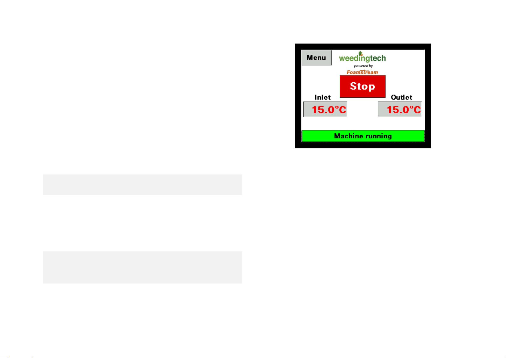
• Press the red stop button pictured on Figure 17. All
lights will extinguish apart from the white ‘power’ light
and the red fault light. The red fault light will remain
on until the water temperature in the M1200 drops
to a safe level and the pump stops.
• Wait until the red fault light switches off
• Turn the isolator switch to ‘A’.
• Turn the generator key switch to ‘A’.
DO NOT USE THE EMERGENCY STOP TO STOP THE
MACHINE OTHER THAN IN AN EMERGENCY.
The emergency stop should only be used in an ‘emergency’
for example:
• Water temperature exceeds 120 degrees centigrade
• Steam emits from the lance
• A significant leak occurs
IF THE EMERGENCY STOP HAS BEEN USED THE M1200
SHOULD BE CHECKED BY A COMPETENT SERVICE
ENGINEER, AND ANY FAULTS RECTIFIED BEFORE THE
M1200 IS SWITCHED BACK ON AGAIN.
Figure 17 – Stop button showing on the PLC
Page 24
M1200 – User manual – English (EU) – 01/03/2018 - ISSUE 2
24
11. Basic fault finding
The PLC of the M1200 is designed to help the user in case
something goes wrong.
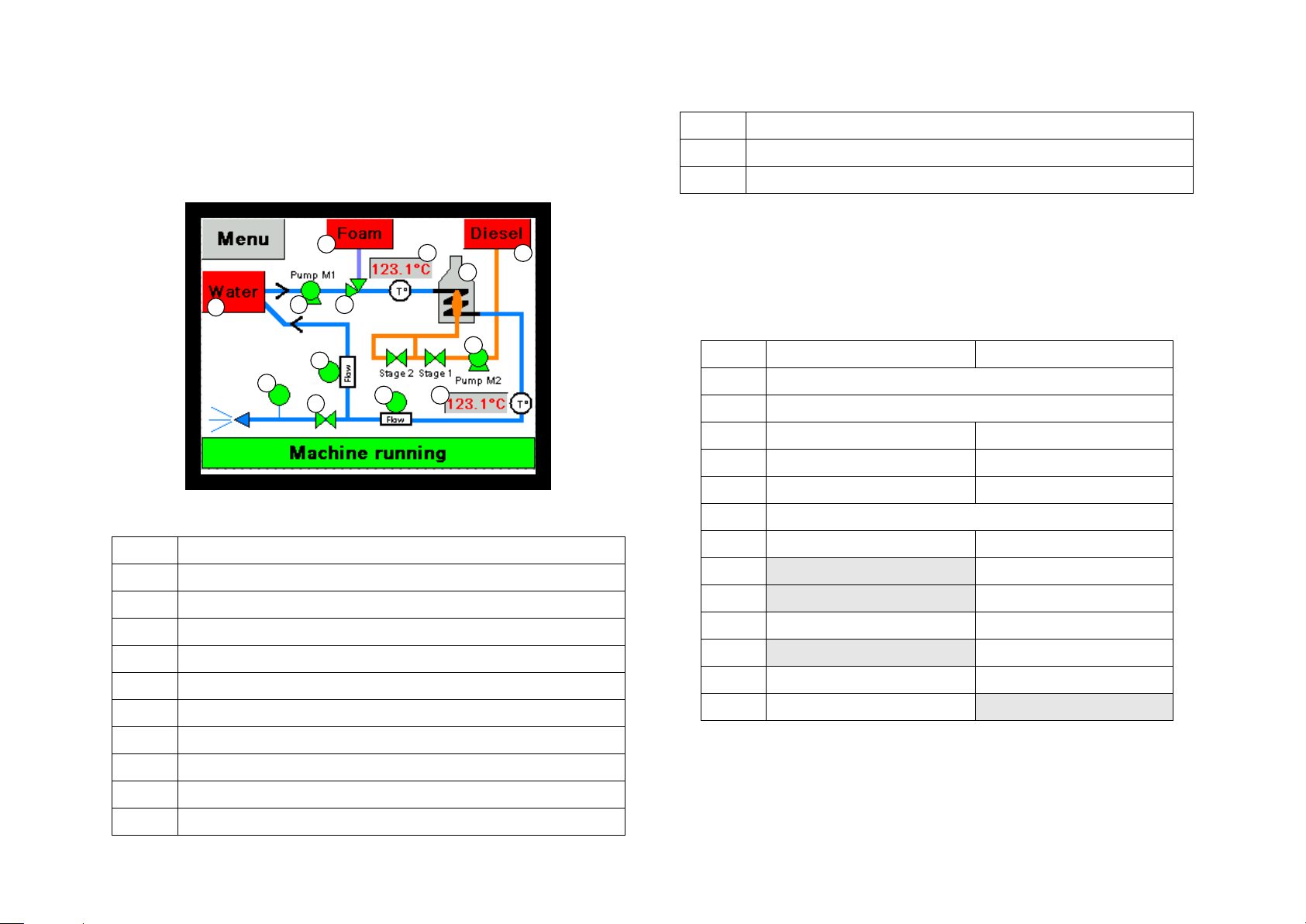
Figure 18 – Summary screen of the PLC
Num.
Description
1
Boiler incoming water temperature
2
Boiler outgoing water temperature
3
Foamstream tank level sensor
4
Water tank level sensor
5
Diesel level sensor
6
Boiler controller
7
Water pump
8
Venturi
9
Lance solenoid valve
10
Lance flow switch
11
Lance pressure switch
12
Boiler diesel pump
13
Return to tank flow switch
Green colour indicates that the sensor is seeing a signal and
grey or red that it doesn’t. Red colour does not necessarily
mean that there is an issue with the sensor. Normal sensor
states during start-up/shut-down and normal operation are
described in the table below.
Num.
Start-up
Running
1
Not applicable
2
Not applicable
3
Green
Green
4
Green
Green
5
Green
Green 6 Should be visible
7
Green
Green
8
Grey
Green
9
Grey
Green
10
Green
Green
11
Grey
Green
12
Green
Green
13
Green
Grey
When a fault occurs, a fault message will be displayed in the
box no4 of Figure 14. Below are the faults that can appear
in that screen and what they mean.
1
2
3
4
5
6
7
8
9
10
11
12
13
Page 25

M1200 – User manual – English (EU) – 01/03/2018 - ISSUE 2
25
Sentence
Colour
Explanation
Machine running
Green
Machine is running and
producing foam
Clear fault
Red
Press the red button on
front panel to clear the fault
Outlet temp. too
high
Red
The temperature at boiler
outlet is too high. Clean the
water filter and check for
leaks. If the problem
persists, please contact
your WTL distributor
Inlet temp. too
high
Red
The temperature in the
main water tank is too high
(more than 45C) and the
machine has stopped. Let
the water cool down in the
tank or top it up with cooler
water.
Low level in
foam tank
Yellow
The foam level is low, the
machine will keep running 2
minutes and will then stop.
Please top up.
Low level in
water tank
Yellow
Same as above
Low level in
diesel tank
Yellow
Same as above
Outlet pressure
too low
Red
The lance valve is open and
the flow is ok but there is
no signal from the pressure
switch. Please control the
pressure on the pressure
gauge of the side panel. If
the pressure is below 5 bars
this means you have no
lance or a large leak before
the lance. If the pressure is
above 5 bars you might
have an issue with the
pressure switch and need to
change it
Boiler fault,
press "Reset"
Red
Press "Reset". If the boiler
does not start, stop the
machine and restart it. If
the problem persists, please
call a Weedingtech
distributor.
Boiler could not
start
Red
20s after the start-up signal
is given, the boiler is not
started. Press "Reset" and
try again. If the boiler does
not start, stop the machine
and restart it. Check on the
summary screen that “stage
1” and “stage 2” are in
green, if not check that the
plugs have not fallen out of
the boiler. If that is not the
case and the problem
persists, please call a
Weedingtech distributor.
Page 26

M1200 – User manual – English (EU) – 01/03/2018 - ISSUE 2
26
Boiler not ready
Red
The boiler fan is running
but the boiler is not running
as the ‘ready’ signal from
controller was not received.
Push on the ‘reset’ button
for 5 seconds and try again.
If the problem persists,
please call your
Weedingtech distributor.
Emergency stop
activated
Red
The emergency stop button
is activated, release it and
press "reset".
No flow at outlet
Red
The pump is running but no
flow is detected. Please
check the hydraulic panel
for leaks. If no leaks are
found, the flow switch
might be faulty.
No flow at
bypass
Red
The pump is running and
the water heating up but no
flow is detected in the
return to tank line. Please
check the hydraulic panel
for leaks. If no leaks are
found, the flow switch
might be faulty.
Press "Air bleed"
Green
Press "Air bleed"
Machine ready,
press "Start"
Green
Press "Start"
Boiler starting
up
Yellow
Nothing
Water & Boiler
pre-heating
Yellow
The boiler is warming up
the water to reach 95° and
will then open the lance
valve. You have nothing to
do.
Air bleeding in
progress
Green
Wait until the bleeding is
complete
Pressure sensor
fault
Red
The pump is not running
but the pressure sensor
sends a signal. The
pressure sensor is faulty
and needs to be changed
Outlet flow
sensor fault
Red
The pump is not running
but the flow sensor sends a
signal. The flowswitch
needs to be changed
Inlet flow sensor
fault
Red
The pump is not running
but the flow sensor send a
signal. The flowswitch
needs to be changed
Boiler controller
fault
Red
The boiler is not running
but ready signal from
controller is received.
Please contact a
Weedingtech distributor
Water pump
speed inverter
fault
Red
Fault signal from speed
inverter. Please stop and
start the machine. If the
problem persists you will
need to contact a
Weedingtech distributor to
open the electrical box and
reset the inverter.
Release trigger
Yellow
Release the trigger.
Page 27
M1200 – User manual – English (EU) – 01/03/2018 - ISSUE 2
27
Manual bleeding
required
Red
You need to bleed the air
from the unit manually by
unscrewing the blue tap on
top of the water filter to let
air go out.
The table below explains what to do to solve an issue when
the sentence above appears on the screen.
The table below lists other basic faults which can be
diagnosed and rectified by a competent M1200 operator.
Please refer to the training documentation provided during
training.
BEFORE BEGINNING ANY WORK ENSURE THE
WEEDINGTECH M1200 HAS BEEN SWITCHED OFF, AND
THE ELECTRICAL SUPPLY FROM THE GENERATOR IS
DISCONNECTED. WARNING: WATER IN THE M1200 MAY
BY HOT.
THE M1200 SHOULD BE SWITCHED OFF AND
CHECKED BY A COMPETENT SERVICE ENGINEER IF THE
OPERATOR IS UNABLE TO DIAGNOSE AND RECTIFY A
FAULT USING THE TABLE BELOW, OR IF A FAULT
PERSISTS.
SYMPTOM
CAUSE
REMEDY
Generator will
not start (no
lights)
Battery is flat
Charge battery
No fuel in tank
Refill tank and
bleed fuel system
Air in the fuel
pipe
Prime fuel using
the in-line hand
pump
The PLC will not
illuminate
Generator is not
started
Start generator
Main switch is
still on ‘OFF’
position
Turn main switch
on ‘ON’ position
Boiler will not
fire up.
(pump runs, red
fault light on)
Air in water feed
line
Stop the machine
and bleed water
once again
Water filter
blocked
Clean and replace
filter
Hot water in tank
Drain tank and
refill with cold
water
Boiler control box
safety switch
activated
Press reset button
on boiler control
box
Boiler switched
off at boiler
control box
Turn switch on
boiler control box
to ‘on’
Flow too low
Check water filter
is clean
No water flows
from lance
Water
temperature too
low
Wait until water
temperature
reaches correct
level
No water in the
water tank
Refill water tank
Intermittent
Flow (amber
light on,
intermittent
green light)
Water
temperature too
low
Wait until water
temperature
reaches correct
level
Page 28

M1200 – User manual – English (EU) – 01/03/2018 - ISSUE 2
28
Steam coming
from lance
Temperature
control system
faulty
Switch off M1200
and call
competent service
engineer
Red light
flashing
Water and/or
Foam and/or
Diesel level too
low
Check water
and/or
Foamstream®
and/or diesel
levels and re fill as
needed.
Red reset light
on
Electrical fault
Press reset button
on control panel
No foam coming
out of the lance
No foam in the
tank
Fill up tank with
foam
Breathing screw
of the foam tank
too tight (air not
getting through)
Loosen the
breathing screw
on top of the cap
of the foam tank
Foam filters
clogged
Clean foam filters
using hot water or
replace them
Dosage plate
blocked
Clean dosage
plate using warm
water
Pressure too high
(more than 18
bars)
Untighten
pressure relief
valve to reach 12
to 15 bars
operating pressure
Foam is too cold
and has
separated
Drain foam from
tank, clean pipes,
filter and dosage
plate holder, remix foam and refill
tank.
Air coming in the
foam system
Check the foam
pipe for air
contamination.
Then tighten the
faulty connection
Page 29
M1200 – User manual – English (EU) – 01/03/2018 - ISSUE 2
29
12. Service checks and intervals
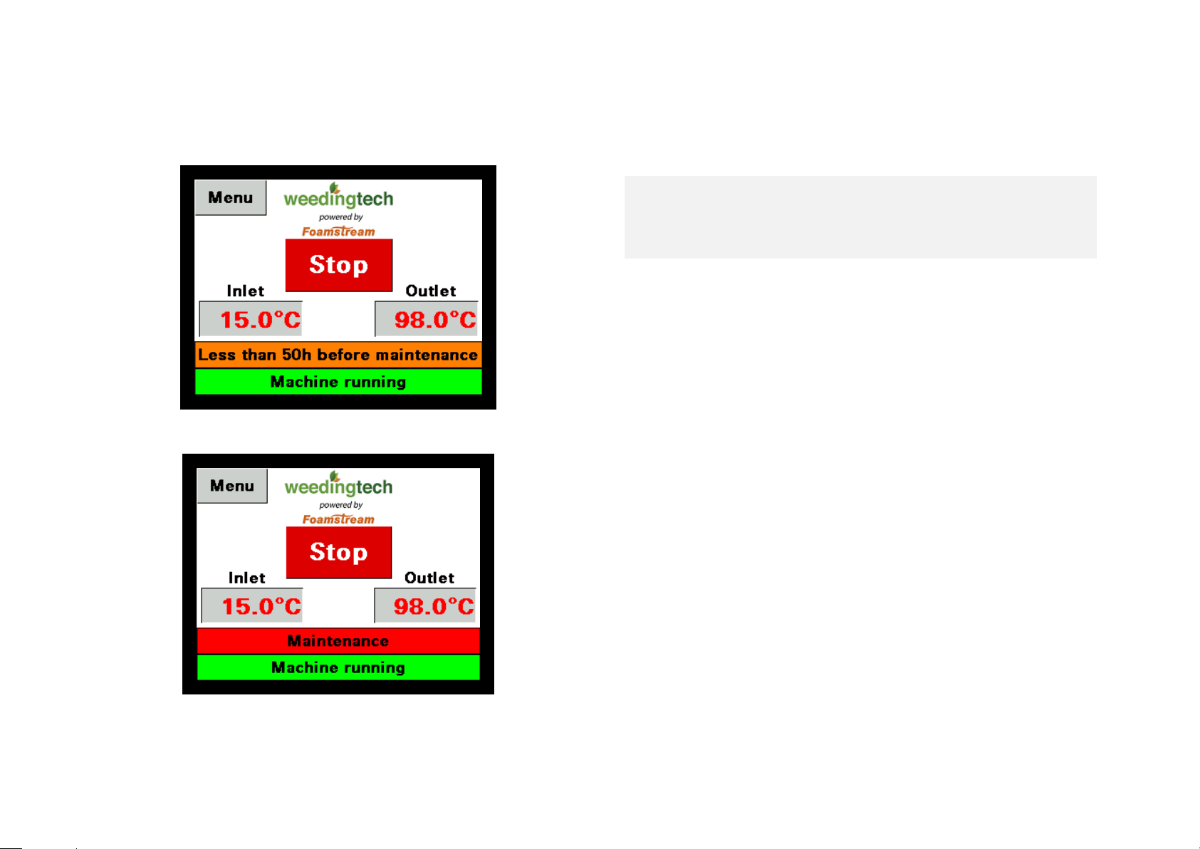
Figure 19 – 50 hours before maintenance
Figure 20 – Maintenance due
The PLC screen will let you know 50 hours before the first
major maintenance of the unit, as depicted on Figure 19.
Once the maintenance is due, Figure 20 will show.
BEFORE BEGINNING ANY WORK ENSURE THE
WEEDINGTECH M1200 HAS BEEN SWITCHED OFF,
AND THE ELECTRICAL SUPPLY FROM THE
GENERATOR IS DISCONNECTED.
EVERY 250 HOURS (6 MONTHS MAXIMUM)
• Change generator oil
• Check boiler flue gas for CO content,
adjust air flap setting if required
• Check and de-scale coil (if necessary)
• Change particulates filter cartridge (if applicable)
EVERY 500 HOURS (12 MONTHS MAXIMUM)
• Change generator oil filter
• Change generator air filter
• Check and adjust and clean generator injectors
• Check and adjust and clean generator valve and
rocker head clearance
• Change fuel filter.
• Check and clean boiler mixing device.
Replace electrodes and nozzles if
necessary
• Check and adjust boiler burner pressure regulator
setting
• Check and clean boiler burner chamber
• Check electrical control panel for moisture damage
• Check and adjust boiler pump oil pressure and level
• Change particulates filter cartridge (if applicable)
EVERY 750 HOURS (OR 18 MONTHS MAXIMUM)
• Change pump oil and filter cartridge (if applicable)
Page 30
M1200 – User manual – English (EU) – 01/03/2018 - ISSUE 2
30
13. Loading and handling
Before lifting the M1200 you should make sure that the
water tank is not full of water. This could result in a serious
damage to the machine if the tank is attached to the frame.
THE M1200 SHOULD NOT BE LIFTED WITH A FULL
TANK OF WATER
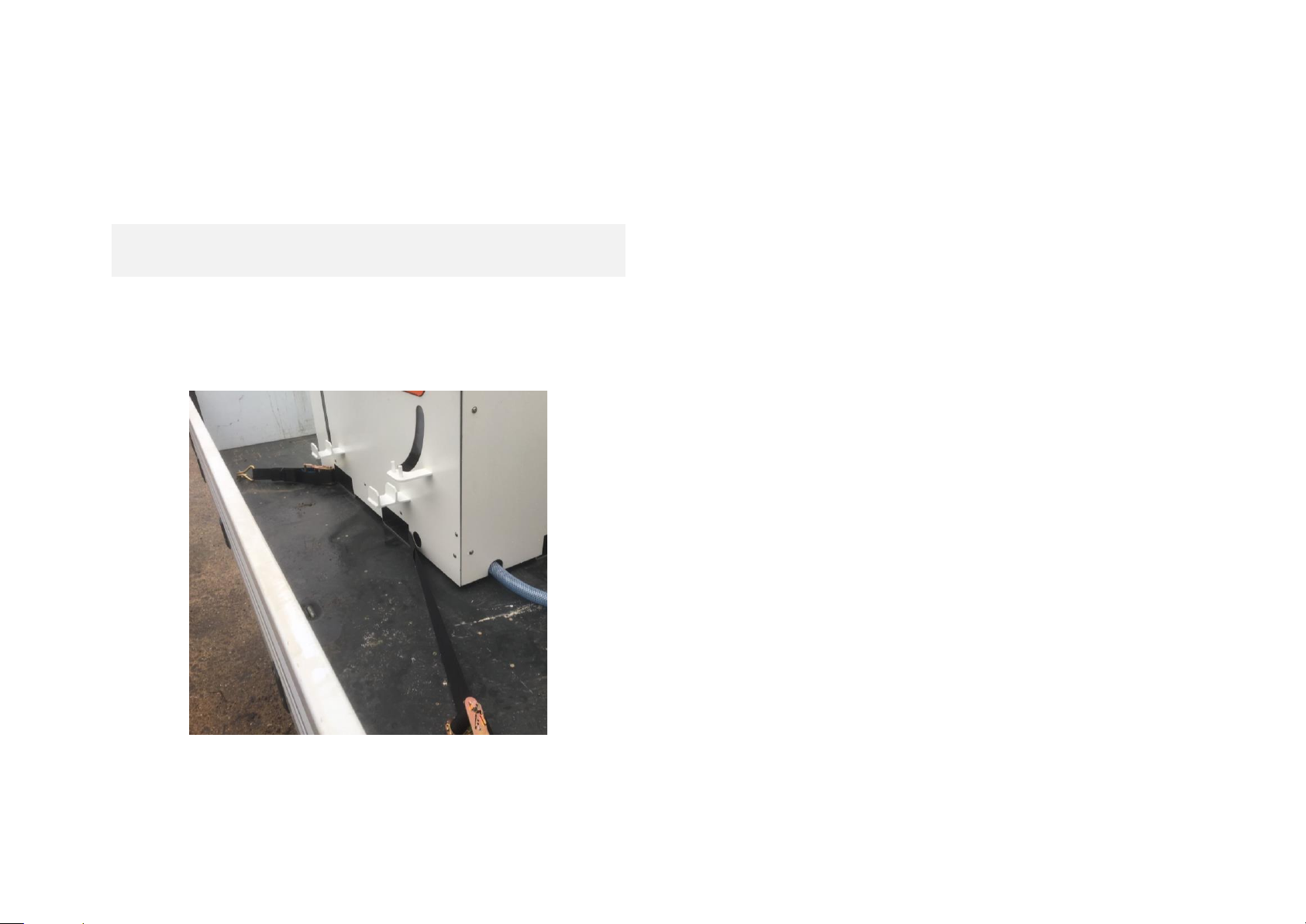
Before driving, the user should make sure that the unit and
the water tank are appropriately strapped or bolted to the
vehicle.
Figure 21 - Strapping of the M1200 to the vehicle
Page 31
M1200 – User manual – English (EU) – 01/03/2018 - ISSUE 2
14. Schematics
Figure 22 – Foam and water schematics
WATER TANK
WATER FILTER
WATER PUMP VENTURI
FOAM TANK
FOAM FILTER 1
FOAM FILTER 2
BOILER
PRESSURE
RELIEF VALVE
LANCE
Page 32
M1200 – User manual – English (EU) – 01/03/2018 - ISSUE 2
32
Figure 23 – Fuel schematics
DIESEL TANK
DIESEL FILTER
GENERATORHAND PUMP
LEVEL SENSOR
BOILER
Page 33
M1200 – User manual – English (EU) – 01/03/2018 - ISSUE 2
Figure 24 – Electrics schematics
KEY SWITCH
GENERATOR
ISOLATOR
CONTROL BOX
CONTROL
PANEL
BOILER
PUMP
LANCE VALVE
PRESSURE
SWITCH
TEMPERATURE
SENSOR INLET
TEMPERATURE
SENSOR OUTLET
LANCE FLOW
SWITCH
BYPASS FLOW
SWITCH
LEVEL SWITCH
FOAM
LEVEL SWITCH
WATER
LEVEL SWITCH
DIESEL
Page 34

M1200 – User manual – English (EU) – 01/03/2018 - ISSUE 2
15. Warranty
(a) The following is an inexhaustive summary of relevant
aspects of the standard terms and conditions of Weeding
Technologies Ltd (“WTL”) and is subject to those terms and
conditions and to any special terms and conditions agreed
between the parties. Where this summary and WTL’s
standard terms and conditions conflict, those terms and
conditions take precedence (and any special terms and
conditions take precedence both over WTL’s standard terms
and conditions and over this document). You are advised to
read the full terms and conditions including so as to take
note of further exclusions of liability.
(b) In no case (without express written agreement, and save
as required by law) does WTL accept any liability towards
any person other than the person (“you”) who originally
made the purchase from WTL or in respect of any alleged
defect not notified by you to WTL within 12 months from
delivery.
You are notified that the standard warranty period given by
the manufacturer is 12 months from delivery.
(c) You must inspect all goods thoroughly with 7 days of
delivery. Subject to the rules set out in section 3 below, any
claim must be notified to WTL within 7 days of delivery or
(subject to clause (b) above) in the case of any defect which
is not reasonably apparent on inspection then within seven
days of the defect coming to your attention (or of the date
when the defect reasonably should have been apparent to
you, if earlier).
(d) Subject to section 3 below, WTL will have no liability if
you do not comply with the above.
(e) WTL’s options, in cases where it is liable, include
repairing or replacing defective goods and allowing you
credit for them. If WTL exercises such an option it has no
further liability. In any event, the liability of WTL is limited
to parts, freight and a limited amount of labour as set out in
WTL’s standard terms and conditions. Labour in excess of
such limits will be at your cost in any event.
(f) You must, if so requested in writing by WTL, at your risk
promptly return any goods the subject of any claim and any
packing materials securely packed and carriage paid to WTL
for examination. (If the claim is substantiated, WTL will
normally reimburse these costs)
(g) If any repairs, modifications, or adjustments are carried
out upon goods other than by WTL or personnel that hold a
valid training certificate or are an authorised sub-contractor
then WTL will have no liability in respect of those goods.
(h) WTL does not accept any liability to you for any loss or
damage of any nature except as expressly stated in the
standard terms and conditions (or in such terms and
conditions as may be specially agreed between you and
WTL). This means among other things that WTL has no
liability for consequential losses, property damage,
penalties, liquidated, exemplary or aggravated damages,
downtime, loss of goodwill, capital costs or any pure
economic loss.
(i) Subject to section 3 below, WTL does not accept any
liability for defects resulting from wear and tear, accident,
improper use or use except in accordance with the
Page 35

M1200 – User manual – English (EU) – 01/03/2018 - ISSUE 2
35
instructions or advice of WTL or authorised dealer or neglect
or from any instructions or materials provided by you. Please
note that this means WTL cannot accept liability in the event
of use of unauthorised foam concentrate or alteration in
factory foam additive dosage settings. Please note that it is
not to be inferred or implied from the fact that WTL may
supply you with any technical means of altering the settings
for the use of the goods that you have any contractual or
other legal protection in the event that you do so - any
alterations to the settings for the use of the Units if not made
in accordance with WTL's or the manufacturer's express
written instructions are made at your own risk.
Page 36
M1200 – User manual – English (EU) – 01/03/2018 - ISSUE 2
36
16. Product certification
M1200 is CE certified. Noise measurements and certification
are available upon request.
Some specific versions of M1200 are CSA and UL certified.
Documents and specification are available upon request.
 Loading...