

Page 1

Operator's Manual
26" RiDiNG MOWER
SiDE DISCHARGE
ELECTRIC START
Catalog No.
28600
IMPORTANT:
Read and follow all Safety
Rules and Instructions before
operating this equipment.
Patents Pending
436518
Page 2

Warranty .................................................. 2
Safety Rules ........................................... 3
Product Specifications ............................ 6
Assembly/Pre-Operation ........................ 7
Operation .............................................. 10
Maintenance Schedule ......................... 16
Maintenance ......................................... 16
Service and Adjustments ....................... 20
Storage ................................................. 24
Troubleshooting .................................... 25
Repair Parts .......................................... 27
LIMITED WARRANT'-/'
The Manufacturer warrants to the original consumer purchaser that this product as manufactured is free from defects in mater#
ale and workmanship. For a period of two (2) years from dale of purchase by the original consumer purchaser, we will repair or
replace, at our option, wilhout charge for parts or tabor incurred in replacing parts, any part which we find to be defective due
to maleriafs or workmanship, This Warranty Is sublect to the following limitations and exclusions
t- This warranty does net apply to the engine, battery (except as noted below) or components parts thereof Please refer to
the applicable manufacturer's warranty on these items.
2 Transportation charges for the movement of any power equipment unit or attachment are the responsibility of the purchas-
er. Transportation charges for any parts submitted for replacement under Ihis warranty must be paid by the purchaser
unless such return is requested by the manufacturer.
3. Battery Wa_ranty: On products equipped wilh a Baltery, we will replace, without charge to you, any battery which we find
to be defect_e in manufacture, during the first nfnety (90) days of ownership, After ninety (90) days, we will exchange the
Batter/, charging you 1tt2 of the price of a new Batte_ for each full month from the date of the original sale Battery must
be maintained in accordance with the instructions furnished
4_ The Warranty does not apply to any products used for rental or commercial purposes
5 This Warranty" applies only to products which have bean properly assembled, adjusted, operated, and maintafned in ac-
cordance with the instructions furnished This Warranty does not apply to any product which has been subjected to altera-
tion. m_suse, abuse, improper assembly or instatlatlon, delivery damage, or to normal wear of the product.
6, Exclusions: Excluded from this Warranty are belts, blades, blade adapters, normal wear, normal adjustments, standard
hardware end normal maintenance.
7 In Ihe event you have a claim under this Warranty, you must return the product to an authorized service dealer
Should you have any unanswered questions concerning this Warranty_ please contact:
HOP
Outdoor Products Customer Service Dept,
9335 Harris Comers Parkway
Char]erie. NC 28269 USA
InCanada contact:
HOP
5855 Terry Fox Way
Mississauga. Ontario
LSV 3E4
giving the model number, sedat number and dale of purchase of your product and the name and address of the authorized
dealer Item whom it was purchased
THIS WARRANTY DOES NOT APPLY TO INCIDENTAL OR CONSEQUENTIAL DAMAGES AND ANY IMPLIED WARRAN-
TIES ARE LIMITED TO THE SAME TIME PERIODS STATED HEREIN FOR OUR EXPRESSED WARRANTIES Some areas
do net al!ow lhe limitation of consequential damages or limitations of how long an implied Warranty may last, so the above
_imitations or exclusions may net apply to you This Warranty gives you specific legal rights, and you may have other rights
which vary from locale to locale
This is a limited Warranty within the meaning of that term as defined in the Magnusen-Moss Act of 1975
2
Page 3
DANGER: This cutting machine is capable of amputating hands and feet and throwing
objects, Failure to observe the following safety instructions could result in serious
injury or death.
_WARNING: In order to prevent acciden-
tal starting when setting up, transporting,
adjusting or making repairs, always discon-
nect spark plug wire and place wire where
it cannot contact spark plug.
_WARNING: Do not coast down a hilt in
neutral, you may lose control of the riding
mower.
_!_WARNING: Engine exhaust, some of its
constituents, and certain vehicle components
contain or emit chemicals known to the State
of Californiato cause cancer and birth defects
or other reproductive harm.
_WARNING:This unit is not intended for
towing, or use of wheel weights. Only use
attachments designed specifically for this
riding mower_
_WARNING: Battery posts, terminals and
related accessories contain lead and lead
compounds, chemicals known to the State of
California to cause cancer and birth defects
or other reproductive harm, Wash hands
after handling.
I. GENERAL OPERATION
o Read, understand, and follow all instruc-
tions on the machine and in the manual
before starting°
• Do not put hands or feet near rotating
parts or under the machine. Keep clear
of the discharge opening at all times.
. Only allow responsible adults, who are
familiar with the instructions, to operate
the machine.
. Clear the area of objects such as rocks,
toys, wire, etc,, which could be picked up
and thrown by the blade°
- Be sure the area is clear of bystanders
before operating° Stop machine if anyone
enters the area_
, Never carry passengers.
° Do not mow in reverse unless absolutely
necessary° Always look down and behind
before and while backing.
, Never direct discharged material toward
anyone, Avoid discharging material
against a walt or obstruction, Material may
ricochet back toward the operator. Stop the
blade when crossing gravel surfaces.
• Do not operate machine without the entire
grass catcher, discharge chute, or other
safety devices in place and working.
° Slow down before turning
° Never leave a running machine unat-
tended. Always turn off blade, set park,-
ing brake, stop engine, and remove keys
before dismounting.
• Disengage blade when not mowing. Shut
off engine and wait for all parts to come
to a complete stop before cleaning the
machine, removing the grass catcher, or
unclogging the discharge chute,
° Operate machine only in daylight or good
artificial fighL
• Do not operate the machine while under
the influence of alcohol or drugs.
• Watch for traffic when operating near or
crossing roadways.
° Use extra care when loading or unloading
the machine into a trailer or truck.
. Always wear eye protection when operat-
ing machine.
• Data indicates that operators, age 60
years and above, are involved in a large
percentage of riding mower-related inju-
ries, These operators should evaluate
their ability to operate the riding mower
safely enough to protect themselves and
others from serious injury,
, Keep machine free of grass , leaves or
other debris build-up which can touch hot
exhaust / engine parts and burn. Do not
allow the mower deck to plow leaves or
other debris which can cause build-up to
occur, Clean any oil or fuel spillage before
operating or storing the machine° Allow
machine to coot before storage.
3
Page 4
II. SLOPE OPERATION
Slopes are a major factor related to toss of
control and tip-over accidents, which can
result in severe injury or death. Operation
on all slopes requires extra caution. If you
can not back up the slope or ifyou feel uneasy
on it, do not mow it.
o Mow up and down slopes (15 ° Max), not
across°
• Watch for holes, ruts, bumps, rocks, or
otherhidden objects_ Uneventerrain could
overturn the machine, Tall grass can hide
obstacles.
• Choose a low ground speed so that you
will not have to stop or shift while on the
slope.
• Do not mow on wet grass. Tires may lose
traction,
• Always keep the machine in gear when
going down slopes. Do not shift to neutral
and coast downhill.
• If machine stops while going uphill,
disengage blade, shift into reverse and
back down slowly.
• Avoid starting, stopping, or turning on a
sloper if the tires lose traction, disengage
the blade and proceed slowly straight down
the slope.
° Keep all movement on the slopes slow and
gradual, Do not make sudden changes
in speed or direction, which could cause
the machine to roll over.
• Use extra care while operating machine
with grass catchers or other attachments;
they can affect the stability of the machine.
• Do no use on steep slopes.
• Do not try to stabilize the machine by
putting your foot on the ground.
• Do not mow near drop-offs, ditches, or
embankments. The machine could sud-
denly roll over if a wheel is over the edge
or if the edge caves in.
Ill. CHILDREN
Tragic accidents can occur if the operator
is not alert to the presence of children,
Children are often attracted to the machine
and the mowing activity_ Never assume
that children will remain where you last
saw them.
• Keep children outofthe mowing area and
in the watchful care of a responsible adult
other than the operator,
° Be a]ert and turn machine off ff a child
enters the area.
• Before andwhile backing, look behind and
down for small children.
. Never carny children, even with the blade
shut off. They may fall off and be seriously
injured or interfere with safe machine
operation. Children who have been given
rides in the past may suddenly appear in
the mowing area for another ride and be run
over or backed over by the machine.
• Never allow children to operate the ma-
chine.
. Use extra care when approaching blind
corners, shrubs, trees, or other objects
that may block your view of a child.
IV. SERVICE
SAFE HANDLING OF GASOLINE
To avoid personal injury or property dam-
age, use extreme care in handling gasoline.
Gasoline is extremely flammable and the
vapors are explosive.
• Extinguish all cigarettes, cigars, pipes,
and other sources of ignition.
• Use only approved gasoline container.
° Never remove gas cap or add fuel with
the engine running. Allow engine to cool
before refueling.
• Never fuel the machine indoors.
• Never store the machine orfuet container
where there is an open flame, spark, or
pilot light such as on a water heater or
other appliances.
4
Page 5

• Never fill containers inside a vehicle or
on a truck or trailer bed with plastic liner.
Always place containers on the ground
away from your vehicle when filling.
• Removegas_powered equipmentfromthe
truck or trailer and refuel it on the ground.
If this is not possible, then refuel such
equipment with aportable container, rather
than from a gasoline dispenser nozzle,
o Keep the nozzle in contact with the rim
of the fuel tank or container opening at
all times until fueling is complete. Do not
use a nozzle lock-open device.
• Iffuel is spilled on clothing, change clothing
immediately.
° Never overfill fuel tank. Replace gas cap
and tighten securely.
GENERAL SERVICE
• Never operate machine in a closed area,
• Keep all nuts and bolts tight to be sure the
equipment is in safe working condition.
• Never tamper with safety devices, Check
their proper operation regularly.
• Keep machine free of grass, leaves, or
other debris build-up. Clean oilorfuelspill-
age and remove any fuel-soaked debris,
Allow machine to cool before storing.
• If you strike a foreign object, stop and
inspect the machine° Repair, ifnecessary,
before restarting.
° Never make any adjustments or repairs
with the engine running°
• Check grass catcher components and the
discharge chute frequently and replace
with manufacturer's recommended parts,
when necessary_
o Mower blade is sharp. Wrap the blade or
wear gloves, and use extra caution when
servicing them.
, Check brake operation frequently. Adjust
and service as required.
° Maintain or replace safety and instruction
labels, as necessary_
• Be sure the area is clear of bystanders
before operating. Stop machine ifanyone
enters the area.
° Never carp/passengers.
o Do not mow in reverse unless absolutely
necessary. Always look down and behind
before and while backing.
5
Page 6
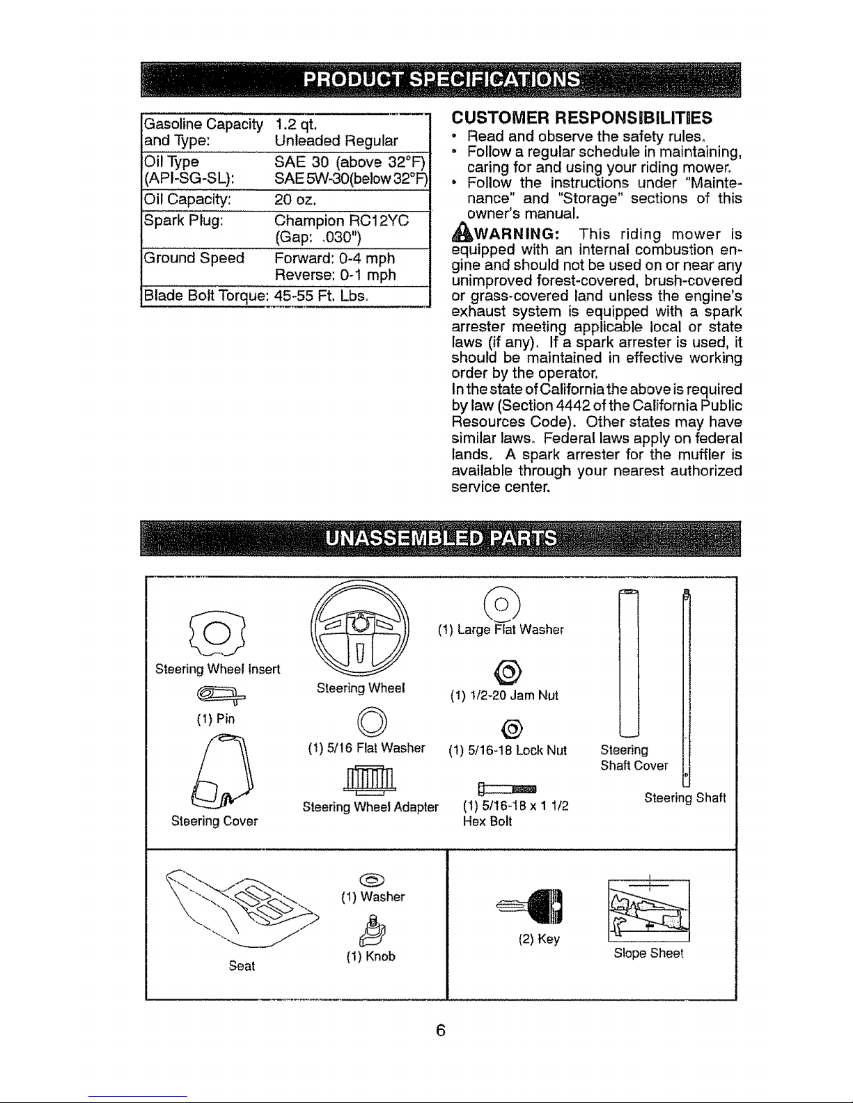
Gasoline Capacity
and Type:
Oil Type
API-SG-SL):
Oil Capacity:
Spark Plug: Champion RC12YC
(Gap: _030")
Ground Speed Forward: 0-4 mph
Reverse: 0-1 mph
Blade Bolt Torque: 45-55 Ft. Lbso
i .2 qt.
Unleaded Regular
SAE 30 (above 32°F)
SAE 5W-30(be!ow 32°F
20 oz.
CUSTOMER RESPONSIBILITUES
• Read and observe the safety rules°
, Follow a regular schedule in maintaining.
caring for and using your riding mower.
, Follow the instructions under "Mainte-
nance" and "Storage" sections of this
owner's manual.
_WARNING: This riding mower is
equipped with an internal combustion en-
gine and should not be used on or near any
unimproved forest-covered, brush-covered
or grass-covered land unless the engine's
exhaust system is equipped with a spark
arrester meeting applicable local or state
laws (if any), if a spark arrester is used, it
should be maintained in effective working
order by the operator,
In the state of California the above is required
by law (Section 4442 of the California Public
Resources Code), Other states may have
similar taws, Federal laws apply on federal
lands, A spark arrester for the muffler is
available through your nearest authorized
service center.
Steering Wheel insert
(1) Pin
Steering Cover
(1) Large Flat Washer
@
Steering Wheel
(1) t/2-20 Jam Nut
© ®
(1) 51!6 FlatWasher (1) 5/16-18 Lock Nut
Steering Wheel Adapter ('I) 5/16-t8 x 1 112
Hex Bolt
t
I
Steering
Shaft Cover
Steering Shaft
Seat
(!) Washer
D
(1) Knob
(2) Key
L
Slope Sheet
6
Page 7
"four new riding mower has been assembled at the factory with the exception of those
parts left unassembted for shipping purposes, To ensure safe and proper operation of your
riding mower all parts and hardware you assemble must be tightened securely. Use the
correct tools as necessary to insure proper tightness.
TOOLS REQUIRED FOR ASSEMBLY
A socket wrench set wilt make assembly
easier. Standard wrench sizes you need
are listed below.
(1) 3/4" wrench
(1) !/2" wrench
(I) Utility knife
(I) Tire pressure gauge
When right or left hand is mentioned in
this manual, it means when you are in the
operating position (seated behind the steer-
ing wheel).
TO REMOVE RIDING MOWER FROM
CARTON
UNPACK CARTON
1. Cut along dotted lines on all four panels
of carton_ Remove carton and top frame
as one unit+
2. Remove packing materials from riding
mower_
NOTE; Only cut carton with a short blade
utility knife, a long blade or saw can puncture
tires on unit.
HOW TO SET UP YOUR RIDING
MOWER
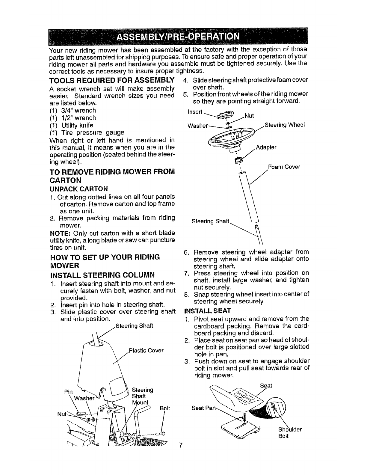
INSTALL STEERING COLUMN
I. Insert steering shaft into mount and se-
curely fasten with bolt, washer, and nut
provided.
2. Insert pin into hole in steering shaft.
3. Slide plastic cover over steering shaft
and into position,
Shaft
Plastic Cover
4. Slide steering shaft protective foam cover
over shafL
5. Position front wheels of the riding mower
so they are pointing straight forward.
Foam Cover
6. Remove steering wheel adapter from
steering wheel and slide adapter onto
steering shaft>
7. Press steering wheel into position on
shaft, install large washer, and tighten
nut securely.
8. Snap steering wheel insert into center of
steering wheel securely.
INSTALL SEAT
1o Pivot seat upward and remove from the
cardboard packing. Remove the card.-
board packing and discard
2. Place seat on seat pan so head of shoul-
der bolt is positioned over large slotted
hole in pan,
3. Push down on seat to engage shoulder
bolt in slot and pull seat towards rear of
riding mower.
Pin Steering
Shaft
Mount
Bolt
Seat
Bolt
Page 8
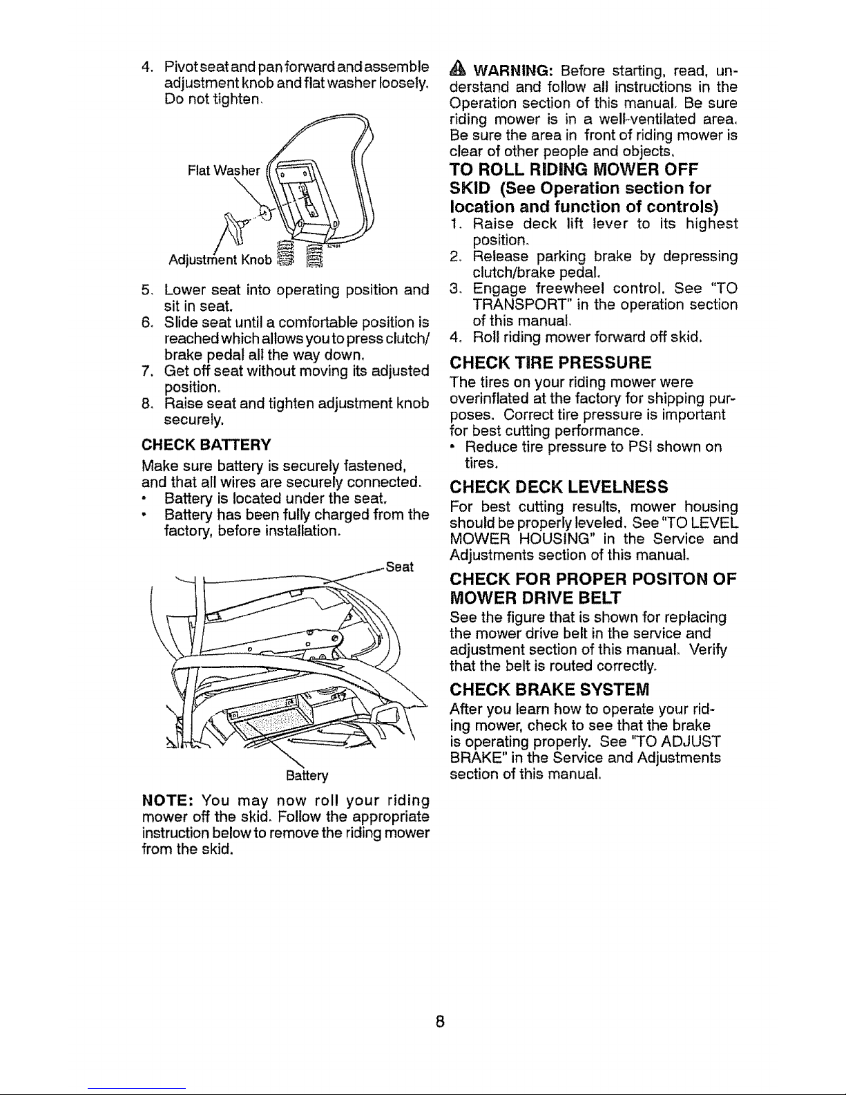
4. Pivot seat and pan forward and assemble
adjustment knob and flat washer loosely,
Do not tighten.
Flat Washer (_
Adjustme_n_t_Knob
5. Lower seat into operating position and
sit in seat.
6. Slide seat until a comfortable position is
reached which allows you to press clutch/
brake pedal all the way down°
7. Get off seat without moving its adjusted
position°
8. Raise seat and tighten adjustment knob
securely,
CHECK BATTERY
Make sure batter,/is securely fastened,
and that all wires are securely connected.
. Battery is located under the seat.
. Battery has been fully charged from the
factory, before instatlation_
Battery
NOTE: You may now rol! your riding
mower off the skid, Follow the appropriate
instruction below to remove the riding mower
from the skid.
WARNING: Before starting, read, un-
derstand and follow all instructions in the
Operation section of this manual, Be sure
riding mower is in a well-ventilated area,
Be sure the area in front of riding mower is
clear of other people and objects,
TO ROLL RIDING MOWER OFF
SKID (See Operation section for
location and function of controls)
1. Raise deck lift lever to its highest
position,
2_ Release parking brake by depressing
clutch/brake pedal,
3, Engage freewheel control. See "TO
TRANSPORT" in the operation section
of this manual,
4. Roll riding mower forward off skid,
CHECK TiRE PRESSURE
The tires on your riding mower were
overinflated at the factory for shipping pur-
poses° Correct tire pressure is important
for best cutting performance.
• Reduce tire pressure to PSI shown on
tires,
CHECK DECK LEVELNESS
For best cutting results, mower housing
should be properly leveled, See "TO LEVEL
MOWER HOUSING" in the Service and
Adjustments section of this manual
CHECK FOR PROPER POSITON OF
MOWER DRIVE BELT
See the figure that is shown for replacing
the mower drive belt in the service and
adjustment section of this manual. "verify
that the belt is routed correctly,
CHECK BRAKE SYSTEM
After you learn how to operate your rid-
ing mower, check to see that the brake
is operating properly. See 'q'O ADJUST
BRAKE" in the Service and Adjustments
section of this manual°
8
Page 9
_/"CHECKLIST
Before you operate your new riding mower,
we wish to assure that you receive the best
performance and satisfaction from this
Quality ProducL
Please review the following checklist:
All assembly instructions have been
completed,
No remaining loose parts in carton.
vf Battery is properly connected.
vf Seat is adjusted comfortably and tight-
ened securely.
vf All tires are properly inflated. (For ship-
ping purposes, the tires were overinflated
at the factory).
#" Be sure mower deck is properly leveled
side-to-side/front-to-rear for best cutting
results. (Tires must be properly inflated
for leveling).
vf Check mower belt. Be sure it is routed
properly around pulleys and inside all belt
keepers,
v" Check wiring° See that all connections
are still secure and wires are properly
clamped.
J" Before driving riding mower, be sure free-
wheel control isin "transmission engaged"
position (see "TO TRANSPORT" in the
Operation section of this manual).
While learning how to use your riding mower,
pay extra attention to the following important
items:
v" Engine oil is at proper level.
vf Fuel tan k is filled with fresh, clean, regular
unleaded gasoline.
Vf Become familiar with all controls, their
location and function. Operate them
before you start the engine°
vf Be sure brake system is in safe operating
condition,
#" Be sure Operator Presence System and
Reverse Operation System (ROS) are
working properly (See the Operation and
Maintenance sections in this manual),
9
Page 10
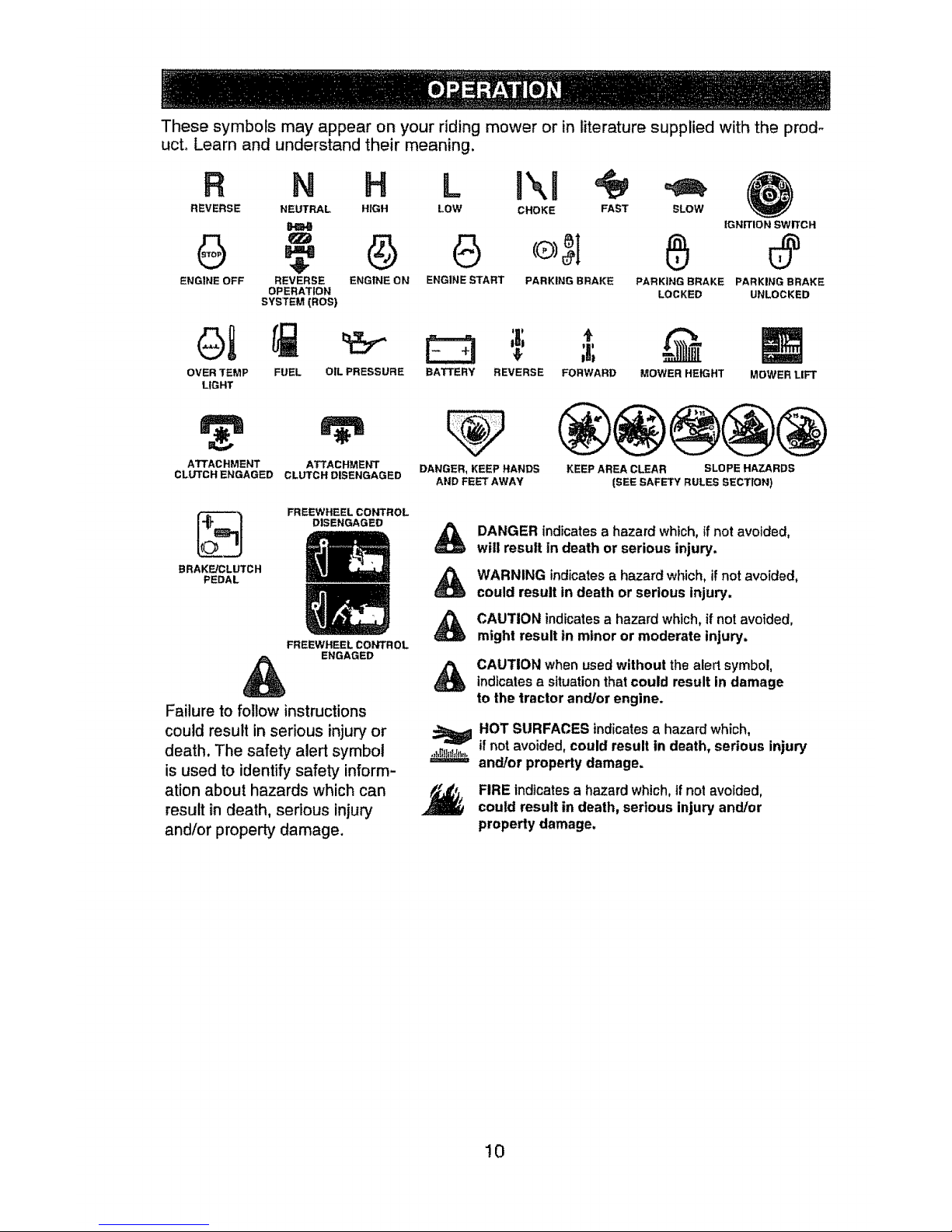
These symbols may appear on your riding mower or in literature supplied with the prod-
ucto Learn and understand their meaning,
R N H L l\J
REVERSE NEUTRAL HIGH LOW CHOKE FAST
ENGINE OFF REVERSE ENGINE ON ENGINE START PARKING BRAKE
OP ERATIOt-,I
SYSTEM (ROS)
SLOW
IGNITION SWITCH
PARKING BRAKE PARKING BRAKE
LOCKED UNLOCKED
ot
OVER TEMP FUEL
LIGHT
;I;
OIL PRESSURE BATTERY REVERSE FORWARD
ATTACHMENT ATTACHMENT DANGER, KEEP HANDS
CLUTCH ENGAGED CLUTCH DISENGAGED AND FEET AWAY
MOWER HEIGHT
MOWER LIFT
KEEP AREA CLEAR SLOPE HAZARDS
(SEE SAFETY RULES SECTION)
BRAKE/CLUTCH
PEDAL
FREEWHEEL CONTROL
DISENGAGED
FREEWHEEL CONTROL
ENGAGED
Failure to follow instructions
could result inserious injury or
death, The safety alert symbol
is used to identify safety inform-
ation about hazards which can
result in death, sedous injury
and/or property damage.
&
&
&
DANGER indicatesa hazardwhtch, tfnot avoided,
will result in death or serious injury.
WARNING indicatesa hazardwhich, ifnot avoided,
could result in death or serious injury,
CAUTION indicatesa hazardwhich,if notavoided,
might result in minor or moderate injury.
CAUTION whenusedwithout the alertsymbol,
indicatesa situationthatcould result in damage
to the tractor and/or engine.
NOT SURFACES indicatesa hazardwhich,
ifnot avoided,could result in death, serious injury
and/or propertydamage.
FIREindicatesa hazardwhich,if not avoided,
could result in death, serious injury and/Dr
property damage.
10
Page 11
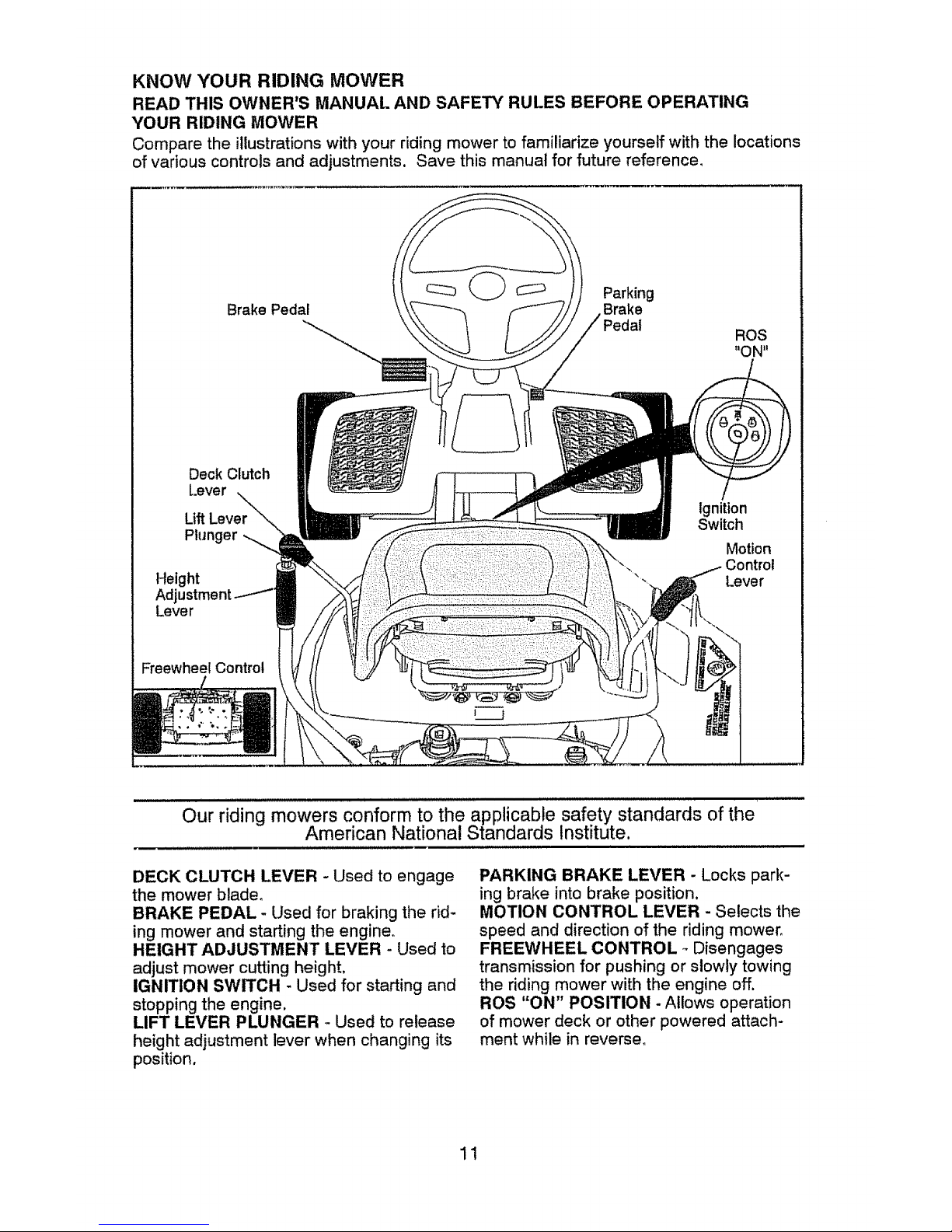
KNOW YOUR RIDING MOWER
READ THIS OWNER'S MANUAL AND SAFEr/' RULES BEFORE OPERATING
YOUR RIDING MOWER
Compare the illustrations with your riding mower to familiarize yourself with the locations
of various controls and adjustments, Save this manual for future reference,
_:_ Parking
Brake Pedal Brake
Deck Clutch
Lever
Lift Lever
Plunger
Height
Adjustm
Lever
Ignition
Switch
Motion
Control
Lever
Freewheel Control
Our riding mowers conform to the applicable safety standards of the
American National Standards Institute.
DECK CLUTCH LEVER - Used to engage
the mower blade,
BRAKE PEDAL - Used for braking the rid_
ing mower and starting the engine°
HEIGHT ADJUSTMENT LEVER - Used to
adjust mower cutting height,
IGNITION SWITCH - Used for starting and
stopping the engine.
LIFT LEVER PLUNGER _ Used to release
height adjustment lever when changing its
position.
PARKING BRAKE LEVER - Locks park-
ing brake into brake position.
MOTION CONTROL LEVER - Selects the
speed and direction of the riding mower.
FREEWHEEL CONTROL _Disengages
transmission for pushing or slowly towing
the riding mower with the engine off.
ROS "ON" POSITION -Allows operation
of mower deck or other powered attach-
ment while in reverser
11
Page 12
The operation of any riding mower can result in foreign objects thrown
into the eyes, which can result in severe eye damage, Always wear
safety glasses or eye shields while operating your riding mower or
performing any adjustments or repairs_ We recommend a wide vision
safety mask over spectacles or standard safety glasses°
HOW TO USE "{OUR RIDING
MOWER
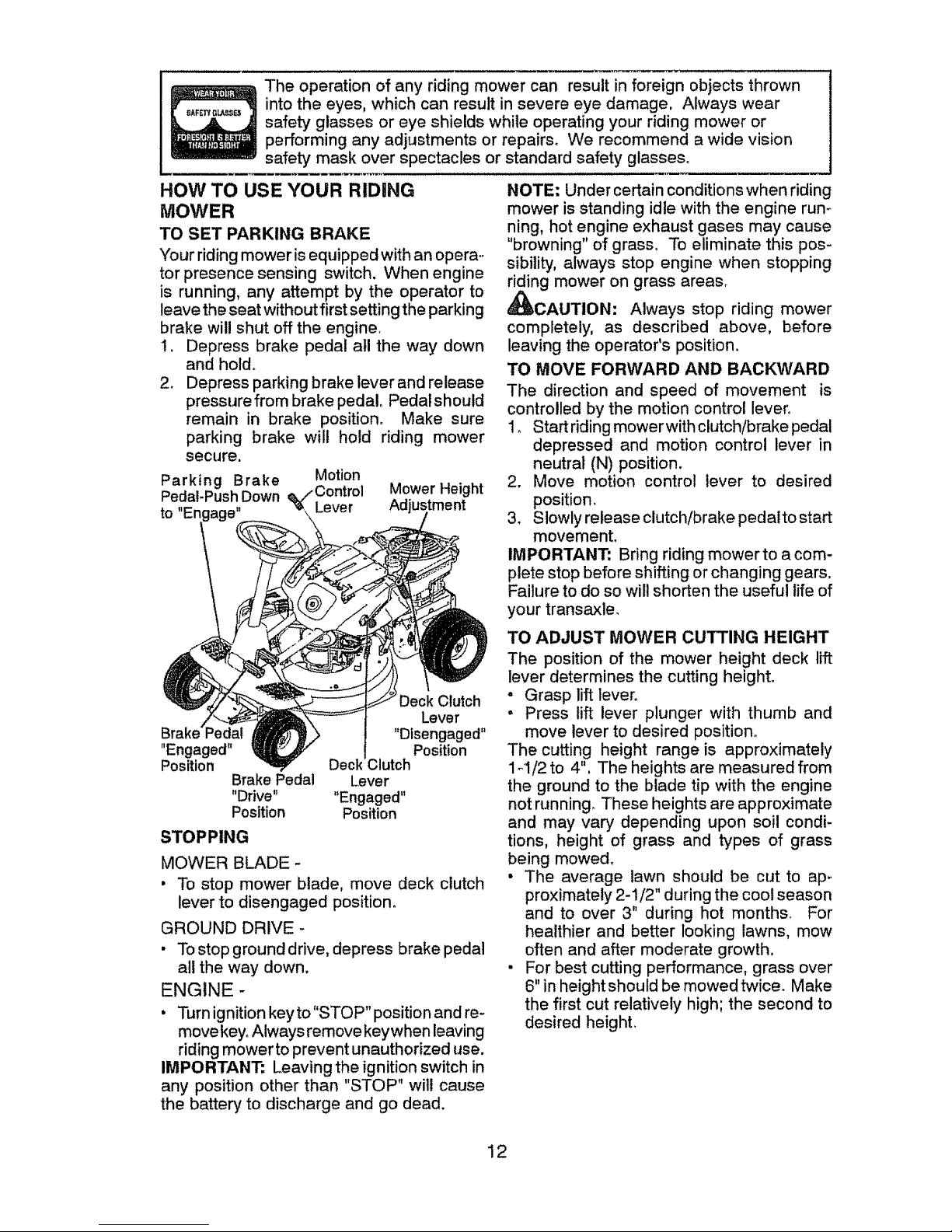
TO SET PARKING BRAKE
"Yourriding mower is equipped with an opera.,
tor presence sensing switch. When engine
is running, any attempt by the operator to
leave the seat without first setting the parking
brake will shut off the engine.
1. Depress brake pedal all the way down
and hold.
2. Depress parking brake lever and release
pressurefrom brake pedal. Pedalshould
remain in brake position° Make sure
parking brake will hold riding mower
secure.
Parking Brake Motion
Pedal-Push Down e,/" Control
_, Lever
to
Mower Height
Adjustment
"Engaged"
Position
Brake Pedal
"Drive"
Position
STOPPING
Deck Clutch
Lever
"Disengaged"
Position
Deck _lutch
Lever
"Engaged"
Position
MOWER BLADE-
• To stop mower blade, move deck clutch
lever to disengaged position.
GROUND DRIVE -
• To stop ground drive, depress brake pedal
all the way down.
ENGINE -
, Turn ignition key to"STOP" position and re-
move key. Always remove keywhen leaving
riding mower to prevent unauthorized use.
IMPORTANT: Leaving the ignition switch in
any position other than "STOP" will cause
the battery to discharge and go dead.
NOTE: Under certain conditions when riding
mower is standing idle with the engine run,°
ning, hot engine exhaust gases may cause
"browning"of grass, To eliminate this pos-
sibility, always stop engine when stopping
riding mower on grass areas.
_CAUTION: Always stop riding mower
completely, as described above, before
leaving the operator's position,
TO MOVE FORWARD AND BACKWARD
The direction and speed of movement is
controlled by the motion control lever°
1, Start riding mower with clutch/brake pedal
depressed and motion control lever in
neutral (N) position.
2. Move motion control lever to desired
position,
3. Slowly release clutch/brake pedal to start
movement.
IMPORTANT: Bring riding mower to a com-
plete stop before shifting or changing gears,
Failure to do so will shorten the useful life of
your transaxle.
TO ADJUST MOWER CUTTING HEIGHT
The position of the mower height deck lift
lever determines the cutting height.
• Grasp lift lever°
• Press lift lever plunger with thumb and
move lever to desired position°
The cutting height range is approximately
1ol/2 to 4", The heights are measured from
the ground to the blade tip with the engine
not running. These heights are approximate
and may vary depending upon soil condi-
tions, height of grass and types of grass
being mowed,
• The average lawn should be cut to ap-
proximately 2-1/2" during the cool season
and to over 3" during hot months. For
healthier and better looking lawns, mow
often and after moderate growth,
• For best cutting performance, grass over
6" in height should be mowed twice. Make
the first cut relatively high; the second to
desired height.
12
Page 13
TO OPERATE MOWER
Your riding mower is equipped with an
operator presence sensing switch. Any
attempt by the operator to leave the seat
with the engine running and the deck clutch
engaged will shut off the engine. You must
remain fully and centrally positioned in the
seat to prevent the engine from hesitating or
cutting off when operating your equipment
on rough, roiling terrain or hills,
1. Select desired height of cut,
2. Start mower blade by engaging deck
clutch lever°
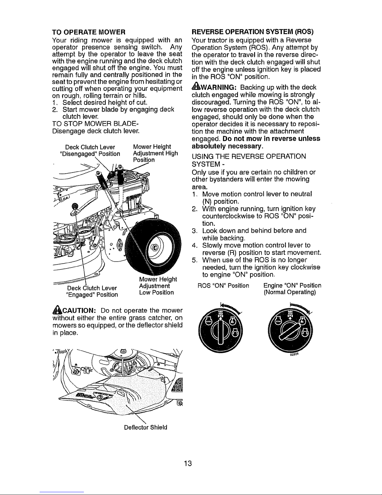
TO STOP MOWER BLADE-
Disengage deck clutch lever_
Deck Clutch Lever
"Disengaged" Position
Mower Height
Adjustment High
Position
Mower Height
Deck lurch Lever Adjustment
"Engaged" Position Low Position
_CAUTION: Do not operate the mower
without either the entire grass catcher, on
mowers so equipped, or the deflector shield
in place,
REVERSE OPERATION S'Y'STEM (ROS)
Your tractor is equipped with a Reverse
Operation System (ROS), Any attempt by
the operator to travel in the reverse direc-
tion with the deck clutch engaged will shut
off the engine unless ignition key is placed
in the ROS "ON" position_
_WARNING: Backing up with the deck
clutch engaged while mowing is strongly
discouraged. Turning the ROS "ON". to a!-
low reverse operation with the deck clutch
engaged, should only be done when the
operator decides it is necessary to reposi-
tion the machine with the attachment
engaged_ Do not mow in reverse unless
absolutely necessary.
USING THE REVERSE OPERATION
SYSTEM -
Only use if you are certain no children or
other bystanders will enter the mowing
area.
1, Move motion control lever to neutral
(N) position.
2. With engine running, turn ignition key
counterclockwise to ROS "ON" posi-
tion.
3, Look down and behind before and
while backing°
4. Slowly move motion control lever to
reverse (R) position to start movement,
5. When use of the ROS is no longer
needed, turn the ignition key clockwise
to engine "ON" position.
ROS "ON" Position
Engine "ON" Position
(Normal Operating)
Deflector Shield
13
Page 14
TO OPERATE ON HILLS
_WARNING: Do not drive up or down
hills with slopes greater than 15 ° and do not
drive across any slope. Use the slope guide
at the back of this manual.
• Choose the slowest speed before starting
up or down hills.
• Avoid stopping or changing speed on
hills,
• if stopping is absolutely necessary, push
clutch/brake pedal quicktyto brake position
and engage parking braker
• Move motion control lever to neutral (N)
position°
• To restart movement, slowly release park-
ing brake and clutch/brake pedal
° Make all turns slowly.
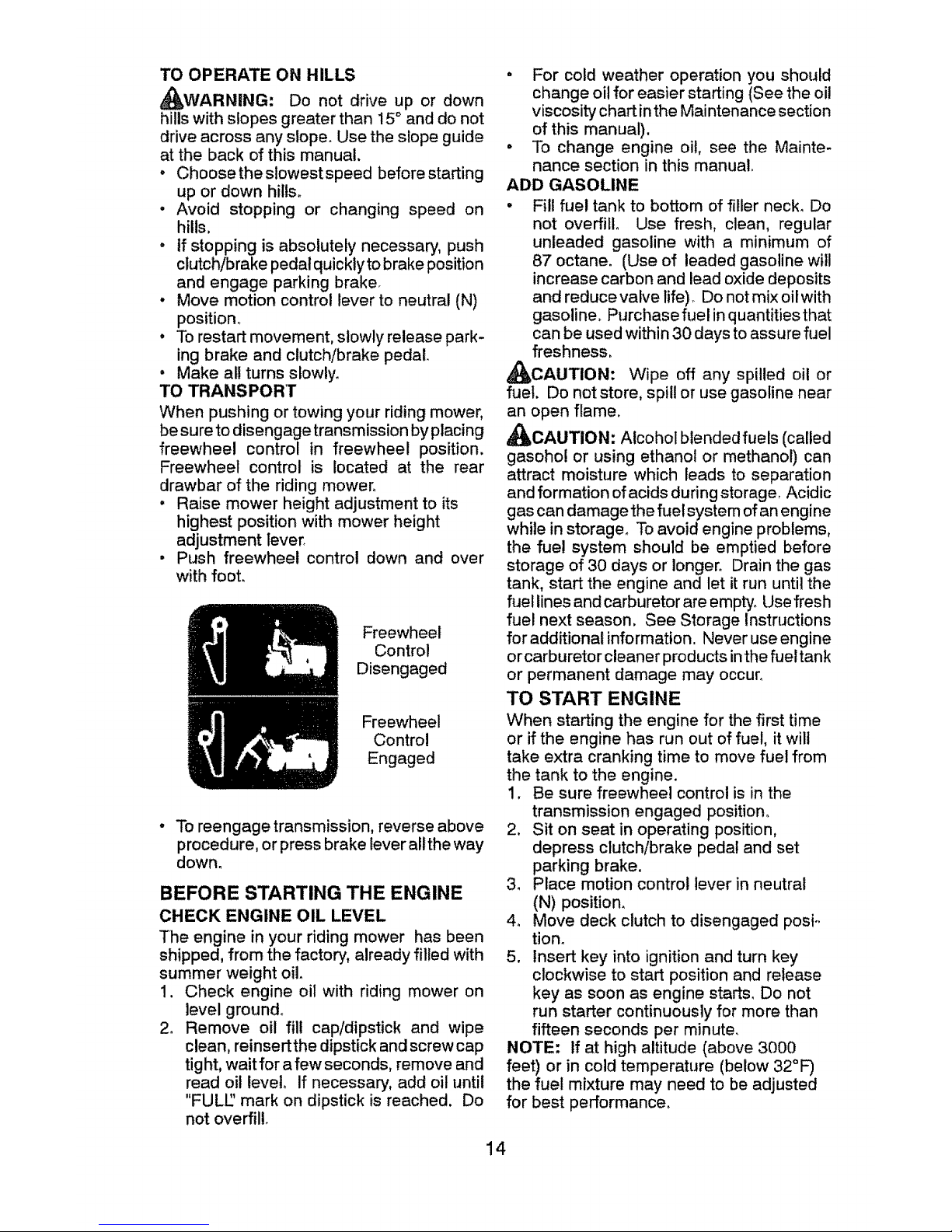
TO TRANSPORT
When pushing or towing your riding mower,
be sure to disengage transmission by placing
freewheel control in freewheel position.
Freewheel control is located at the rear
drawbar of the riding mower°
, Raise mower height adjustment to its
highest position with mower height
adjustment lever.
• Push freewheel control down and over
with foot.
Freewheel
Control
Disengaged
Freewheel
Control
Engaged
• To reengage transmission, reverse above
procedure, or press brake lever allthe way
down.
BEFORE STARTING THE ENGINE
CHECK ENGINE OIL LEVEL
The engine in your riding mower has been
shipped, from the factory, already filled with
summer weight oil.
1. Check engine oil with riding mower on
level ground.
2. Remove oil fill cap/dipstick and wipe
clean, reinsertthe dipstick and screw cap
tight, wait for a few seconds, remove and
read oil level. If necessary, add oil until
"FULl" mark on dipstick is reached. Do
not overfill.
° For cold weather operation you should
change oil for easier starting (See the oil
viscosity chart in the Maintenance section
of this manual).
• To change engine oi!, see the Mainte-
nance section in this manual.
ADD GASOLINE
° Fill fuel tank to bottom of filler neck. Do
not overfill° Use fresh, clean, regular
unleaded gasoline with a minimum of
87 octane. (Use of leaded gasoline will
increase carbon and lead oxide deposits
and reduce valve tife)o Do not mix oil with
gasoline. Purchasefuel in quantities that
can be used within 30 days to assure fuel
freshness.
_CAUTION: Wipe off any spilled oil or
fuel. Do not store, spill or use gasoline near
an open flame.
d_IbOAUTION: Alcohol blended fuels (called
gasohol or using ethanol or methanol) can
attract moisture which leads to separation
and formation of acids during storage. Acidic
gas can damage the fuel system of an engine
while in storage. To avoid engine problems,
the fue! system should be emptied before
storage of 30 days or longer° Drain the gas
tank, start the engine and let it run until the
fueltines and carburetor areempty. Usefresh
fuel next season, See Storage Instructions
for additional information. Never use engine
or carburetor cleaner products in the fuel tank
or permanent damage may occur.
TO START ENGINE
When starting the engine for the first time
or if the engine has run out of fuel, it will
take extra cranking time to move fuel from
the tank to the engine.
1, Be sure freewheel control is in the
transmission engaged position.
2, Sit on seat in operating position,
depress clutch/brake pedal and set
parking brake,
3, Place motion control lever in neutral
(N) position.
4o Move deck clutch to disengaged posi-
tion.
5. Insert key into ignition and turn key
clockwise to start position and release
key as soon as engine starts, Do not
run starter continuously for more than
fifteen seconds per minute,
NOTE: If at high altitude (above 3000
feet) or in cold temperature (below 32°F)
the fuel mixture may need to be adjusted
for best performance,
14
Page 15
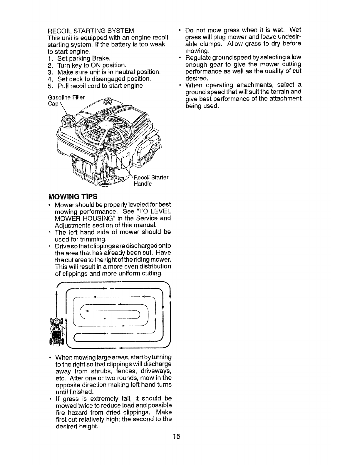
RECOIL STARTING SYSTEM
This unit is equipped with an engine recoil
starting system, if the battery is too weak
to start engine.
1, Set parking Brake.
2, Turn key to ON position.
3, Make sure unit is in neutral position.
4. Set deck to disengaged position°
5. Pull recoil cord to start engine_
Gasoline Filler
Cap
\RecoU Starter
Handle
MOWING TIPS
• Mower should be properly leveled for best
mowing performance, See "TO LEVEL
MOWER HOUSING" in the Service and
Adjustments section of this manual.
, The left hand side of mower should be
used for trimming,
° Drivesothatclippings are discharged onto
the area that has already been cut. Have
the cut area to the right of the riding mower.
This will result in a more even distribution
of clippings and more uniform cutting.
f
, When mowing large areas, start byturning
to the right so that clippings will discharge
away from shrubs, fences, driveways,
etc_ After one or two rounds, mow in the
opposite direction making left hand turns
until finished,
• If grass is extremely tall, it should be
mowed twice to reduce load and possible
fire hazard from dried clippings. Make
first cut relatively high; the second to the
desired height.
15
- Do not mow grass when it is wet, Wet
grass will plug mower and leave undesir-
able clumps, Allow grass to dry before
mowing_
• Regulate ground speed byselecting alow
enough gear to give the mower cutting
performance as well as the quality of cut
desired,
• When operating attachments, select a
ground speed that will suit the terrain and
give best performance of the attachment
being used.
Page 16
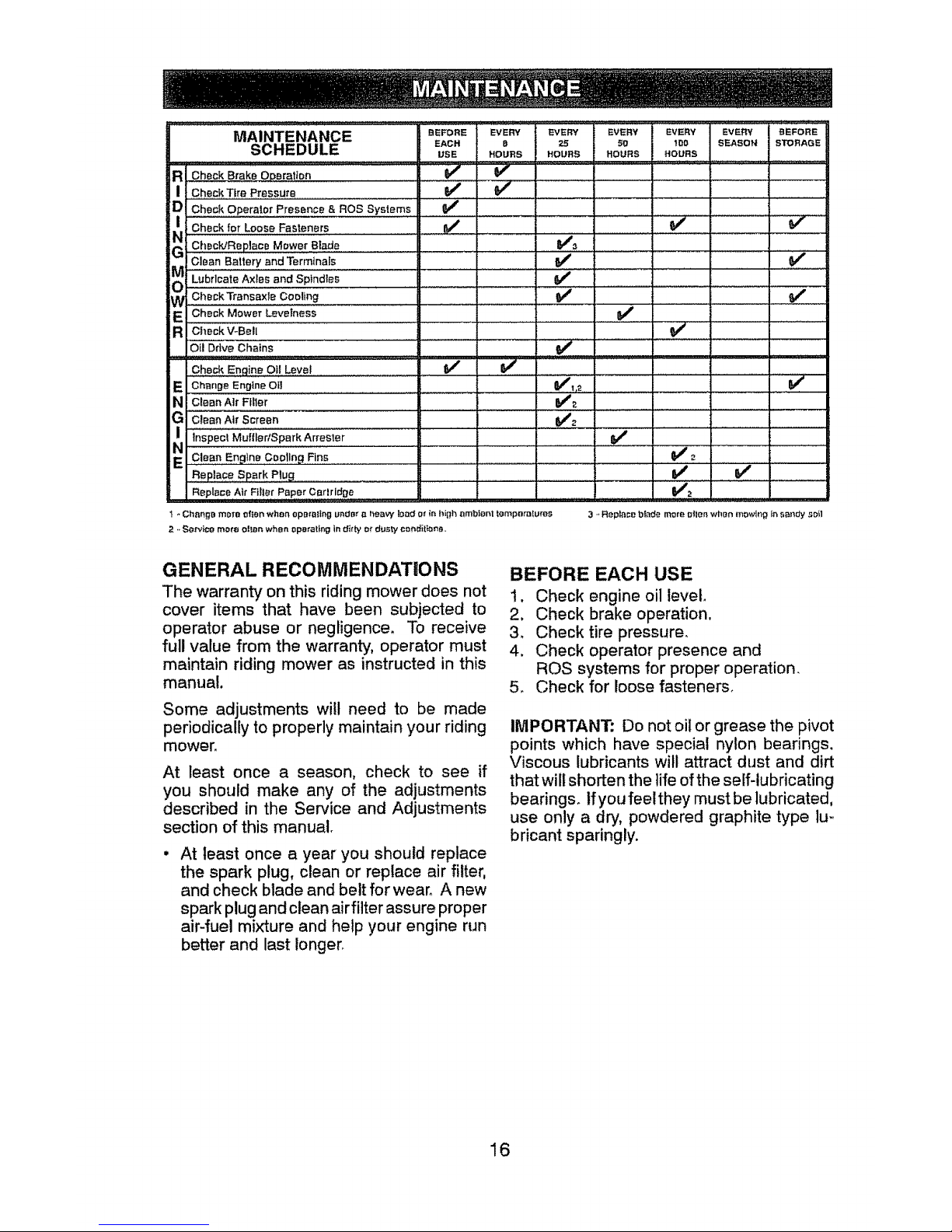
BEFORE EVERY EVERY EVERY EVERY EVERY BEFORE
EACH B 25 50 lEO SEASON STORAGE
USE HOURS HOURS HOURS , HOURS _ _ ,
V' V"
v' ....
J
v"
v'
NI i Check for Loose Fasteners ..................... _'
:Check/Replace Mower B!ade I] I
Check Transaxle Cooling
W Check Mower Levelness
R CheckV-Bell
iCheckEngine 0ti Leve_
E Change Engine Oil
N Clean Air Filter
? Clean Air Screen
Inspect Muffler/Spark Arreeter
EN Clean Engine Cooling Fins
Rap!ace Spark plug _,
Replace Air Filter Paper Cer_ri_ge
v"
v"
v,; ..... , ........
V#2 ............
V' : v'
t - Chnng9 mote of_tn when opo_ating undnr n hez_W lo_d or in high ambient tompotalures
2 - Servi¢o mote ol_n when operating in d_ty or dusty con_it_on_.,
3 -'Replace bla_3e more ldlen when mowing ie _,o_'_dyso_l
GENERAL RECOMMENDATIONS
The warranty on this riding mower does not
cover items that have been subjected to
operator abuse or negligence. To receive
full value from the warranty, operator must
maintain riding mower as instructed in this
manual.
Some adjustments wilt need to be made
periodically to properly maintain your riding
mower.
At least once a season, check to see if
you should make any of the adjustments
described in the Service and Adjustments
section of this manual.
At least once a year you should replace
the spark plug, clean or replace air filter,
and check blade and belt for wear. A new
spark plug and clean air filter assure proper
air-fuel mixture and help your engine run
better and last longer.
BEFORE EACH USE
t. Check engine oil level
2, Check brake operation,
3. Check tire pressure.
4. Check operator presence and
ROS systems for proper operation.
5_ Check for loose fasteners.
IMPORTANT: Do not oil or grease the pivot
points which have special nylon bearings.
Viscous lubricants will attract dust and dirt
that will shorten the life of the self-lubricating
bearings, lfyoufeelthey must be lubricated,
use only a dry, powdered graphite type lu-,
bricant sparingly.
16
Page 17
RIDING MOWER
Always observe safety rules when performing
any maintenance.
BRAKE OPERATION
tf riding mower requires more than four (4)
feet to stop at highest speed in highest gear
on a level, dry concrete or paved surface, then
brake must be service& (See "TO ADJUST
BRAKE" in the Service and Adjustments
section of this manual).
TIRES
, Maintain proper air pressure in all tires
(See PSI on tires).
• Keep tires free of gasoline, oil, or insect
control chemicals which can harm
rubber.
• Avoid stumps, stones, deep ruts, sharp
objects and other hazards that may cause
tire damage.
NOTE= To seal tire punctures and prevent
flat tires due to slow leaks, tire sealant may
be purchased from your local parts dealer.
Tire sealant also prevents tire dry rot and
corrosion,
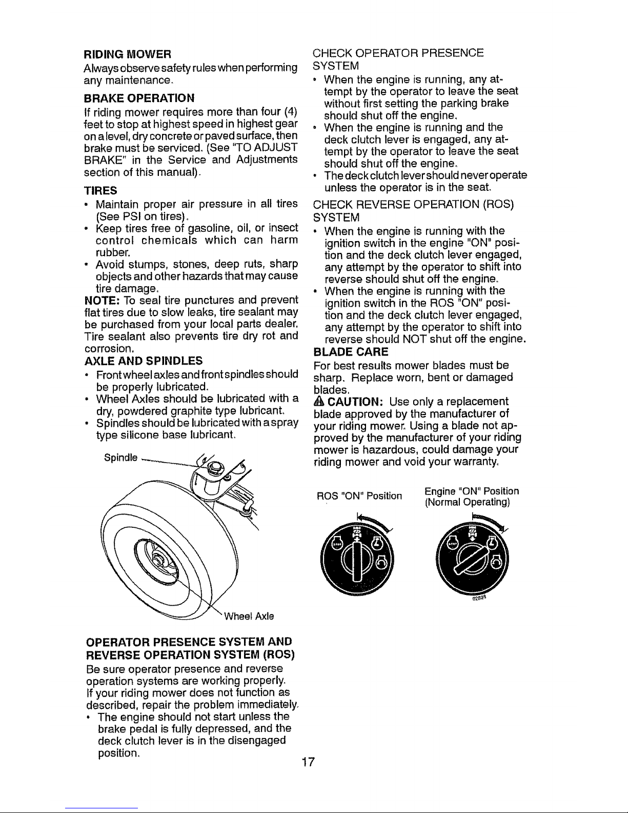
AXLE AND SPINDLES
• Frontwheel axles and front spindles should
be properly lubricated.
• Wheel Axles should be lubricated with a
dry, powdered graphite type lubricant.
• Spindles should be lubricated with aspray
type silicone base lubricant.
Spindle
CHECK OPERATOR PRESENCE
SYSTEM
° When the engine is running, any at-
tempt by the operator to leave the seat
without first setting the parking brake
should shut off the engine°
o When the engine is running and the
deck clutch lever is engaged, any at-
tempt by the operator to leave the seat
should shut off the engine_
, The deck clutch levershould neveroperate
unless the operator is in the seat.
CHECK REVERSE OPERATION (ROS)
SYSTEM
° When the engine is running with the
ignition switch in the engine "ON" posi-
tion and the deck clutch lever engaged,
any attempt by the operator to shift into
reverse should shut off the engine.
• When the engine is running with the
ignition switch in the ROS "ON" posi-
tion and the deck clutch lever engaged,
any attempt by the operator to shift into
reverse should NOT shut off the engine.
BLADE CARE
For best results mower blades must be
sharp. Replace worn, bent or damaged
blades.
_, CAUTION: Use only a replacement
blade approved by the manufacturer of
your riding mower. Using a blade not ap-
proved by the manufacturer of your riding
mower is hazardous, could damage your
riding mower and void your warranty_
ROS "ON" Position
Engine "ON" Position
(Normal Operating)
leef Axle
OPERATOR PRESENCE SYSTEM AND
REVERSE OPERATION SYSTEM (ROS)
Be sure operator presence and reverse
operation systems are working properly.
If your riding mower does not function as
described, repair the problem immediately.
° The engine should not start unless the
brake pedal is fully depressed, and the
deck clutch lever is in the disengaged
position_
17
Page 18
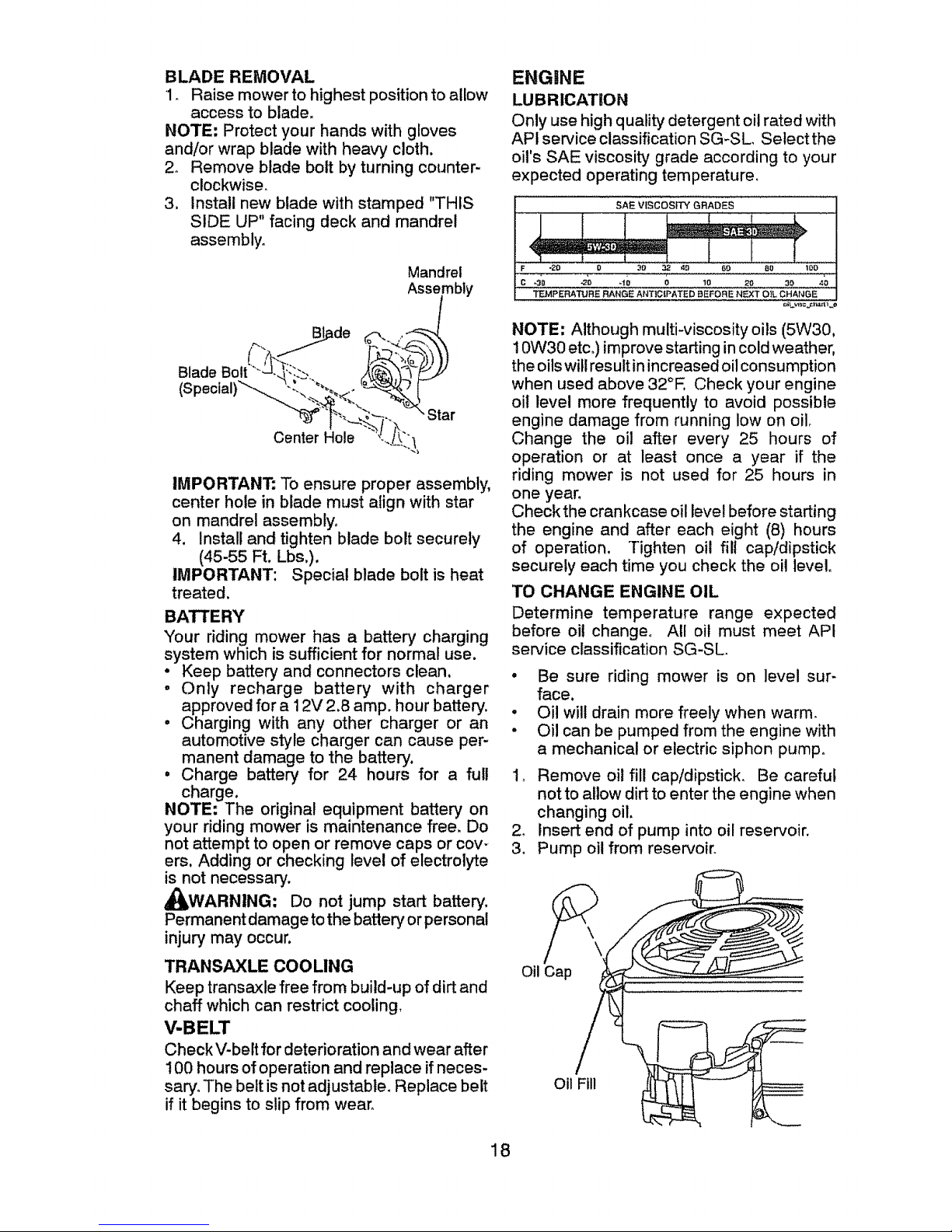
BLADE REMOVAL
1_ Raise mower to highest position to allow
access to blade.
NOTE: Protect your hands with gloves
and/or wrap blade with heavy cloth.
2. Remove blade bolt by turning counter-
clockwise.
3, Install new blade with stamped "THIS
SIDE UP" facing deck and mandrel
assembly.
Mandrel
Assembly
B_de _(;_.<._
(Special)'____ Star
CenterHole ""\!_J_,
IMPORTANT: To ensure proper assembly,
center hole in blade must align with star
on mandrel assembly°
4. Install and tighten blade bolt securely
(45-55 Ft. Lbs,).
IMPORTANT: Special blade bolt is heat
treated.
BATTERY
Your riding mower has a battery charging
system which is sufficient for normal use.
• Keep battery and connectors clean,
, Only recharge battery with charger
approved for a 12V 2.8 amp. hour battery.
° Charging with any other charger or an
automotive style charger can cause per-
manent damage to the battery.
, Charge battery for 24 hours for a full
charge.
NOTE: The original equipment battery on
your riding mower is maintenance free. Do
not attempt to open or remove caps or cov-
ers, Adding or checking level of electrolyte
is not necessary.
_WARNING: Do not jump start battery.
Permanent damage to the battery or personal
injury may occur.
TRANSAXLE COOLING
Keep transaxle free from build-up of dirt and
chaff which can restrict cooling.
V-BELT
Check V-belt for deterioration and wear after
100 hours of operation and replace if neces-
san]. The belt is not adjustable. Replace belt
if it begins to slip from wear.
ENGINE
LUBRICATION
Only use high quality detergent oil rated with
APi service classification SG-SL, Select the
oil's SAE viscosity grade according to your
expected operating temperature_
SAE ViscosrrY GRADES
3_
!c -_o o_o 40 o lO _o _o
TEMPERATURE RANGE ANTIC{PATED BEFORE NEXT OIL CHANGE
NOTE: Although multi-viscosity oils (5W30,
10W30 etc,) improve starting in cold weather,
the oils will result in increased oil consumption
when used above 32°E Check your engine
oil level more frequently to avoid possible
engine damage from running low on oilo
Change the oil after every 25 hours of
operation or at least once a year if the
riding mower is not used for 25 hours in
one year.
Checkthe crankcase oil level before starting
the engine and after each eight (8) hours
of operation. Tighten oil fill cap/dipstick
securely each time you check the oil level°
TO CHANGE ENGINE OIL
Determine temperature range expected
before oil change° All oil must meet API
service classification SG-SL
As
3.
° Be sure riding mower is on level sur-
face.
° Oil will drain more freely when warm.
° Oil can be pumped from the engine with
a mechanical or electric siphon pump.
I_ Remove oil fill cap/dipstick. Be careful
notto allow dirt to enter the engine when
changing oil.
insert end of pump into oil reservoir.
Pump oil from reservoir.
Oil Cap
Oil Fill
18
Page 19
4_
5_
Refill engine with oil through oil fill dipstick
tube, Pour slowly. Do not overfill. For
approximate capacity see "PRODUCT
S PECtFICATIONS"sectionofthis manual
Use gauge on oil fill cap/dipstick for
checking level, For accurate reading,
tighten dipstick cap securely onto the
tube before removing dipstick° Keep oil
at "FULl" line on dipstick_ Tighten cap
onto the tube securely when finished.
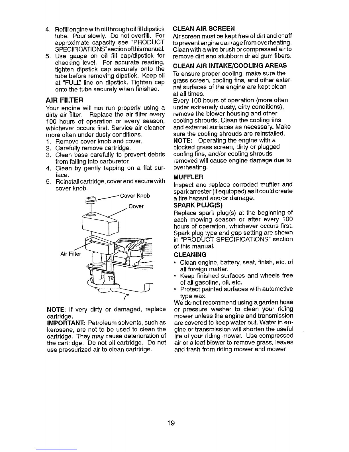
AIR FILTER
Your engine will not run properly using a
dirty air filter. Replace the air filter ever]
100 hours of operation or every season,
whichever occurs first. Service air cleaner
more often under dusty conditions.
1. Remove cover knob and cover.
2, Carefully remove cartridge.
3_ Clean base carefully to prevent debris
from failing into carburetor,
4, Clean by gently tapping on a flat sur-
face°
5. Reinstall cartridge, cover and secure with
cover knob,
Cover Knob
,,_..s.-_ Cover
t
Air Filter
NOTE: If very dirty or damaged, replace
cartridge°
IMPORTANT: Petroleum solvents, such as
kerosene, are not to be used to clean the
cartridge. They may cause deterioration of
the cartridge. Do not oil cartridge, Do not
use pressurized air to clean cartridge,
CLEAN AIR SCREEN
Air screen must be kept free of dirt and chaff
to prevent engine damage from overheating.
Clean with a wire brush or compressed airto
remove dirt and stubborn dried gum fibers.
CLEAN AIR INTAKE/COOLING AREAS
To ensure proper cooling, make sure the
grass screen, cooling fins, and other exter_
nal surfaces of the engine are kept clean
at all times.
Every 100 hours of operation (more often
under extremely dusty, dirty conditions),
remove the blower housing and other
cooling shrouds, Clean the cooling fins
and external surfaces as necessary. Make
sure the cooling shrouds are reinstalled.
NOTE; Operating the engine with a
blocked grass screen, dirty or plugged
cooling fins, and/or cooling shrouds
removed will cause engine damage due to
overheating_
MUFFLER
Inspect and replace corroded muffler and
spark arrester (ifequipped) as itcould create
a fire hazard and/or damage.
SPARK PLUG(S)
Replace spark plug(s) at the beginning of
each mowing season or after every 100
hours of operation, whichever occurs firsL
Spark plug type and gap setting are shown
in "PRODUCT SPECIFICATIONS" section
of this manual.
CLEANING
. Clean engine, battery, seat, finish, etc, of
all foreign matter.
• Keep finished surfaces and wheels free
of all gasoline, oil, etco
. Protect painted surfaces with automotive
type wax.
We do not recommend using a garden hose
or pressure washer to clean your riding
mower unless the engine and transmission
are covered to keep water out. Water in en-
gine or transmission will shorten the useful
life of your riding mower° Use compressed
air or a leaf blower to remove grass, leaves
and trash from riding mower and mower.
19
Page 20
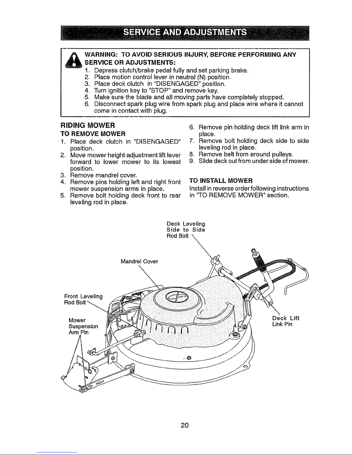
WARNING: TO AVOID SERIOUS INJURY, BEFORE PERFORMING ANY
SERVICE OR ADJUSTMENTS:
1, Depress clutch/brake pedal fully and set parking brake,
2, Place motion control lever in neutral (N) position
3. Place deck clutch in "DISENGAGED" position°
4, Turn ignition key to "STOP" and remove key°
5, Make sure the blade and all moving parts have completely stopped.
6. Disconnect spark plug wire from spark plug and place wire where it cannot
come in contact with plug.
RIDING MOWER
TO REMOVE MOWER
1. Place deck clutch in "DISENGAGED"
position,
2. Move mower height adjustment lift lever
forward to lower mower to its lowest
position.
3, Remove mandrel cover.
4, Remove pins holding left and right front
mower suspension arms in place.
5_ Remove bolt holding deck front to rear
leveling rod in place_
6o Remove pin holding deck lift link arm in
place,
7. Remove bolt holding deck side to side
leveling rod in place,
8, Remove belt from around pulleys,
9. Slide deck outfrom under side of mower.
TO INSTALL MOWER
Install in reverse order following instructions
in "TO REMOVE MOWER" section,
Mandrel Cover
Deck Leveling
Side to Side
Rod Bolt
Front Leveling
Rod Bolt_
Mower
Suspension
Arm Pin
Deck Lift
Link Pin
2O
Page 21
TO LEVEL MOWER HOUSING
Adjust the mower while riding mower is
parked on level ground or driveway. Make
sure tires are properly inflated (See side
of tire for proper PSI)_ tf tires are over or
underinftated, you will not properly adjust
your mower.
SIDE-TO_SIDE ADJUSTMENT
o Raise mower to its highest position.
, Measure distance "A" from bottom edge
of mower to ground level at front corners
of mower_
, To raise the right side ofthe mower, tighten
lift link adjustment nuL
• To iowerthe rightside ofthe mower, loosen
lift link adjustment nut.
NOTE: Each full turn of adjustment nut will
change mower height about 3/16".
Bottom Edge of Bottom Edge of
Mower to Ground Mower to Ground
[fi!tl II !illf
, Recheck measurements after adjusting.
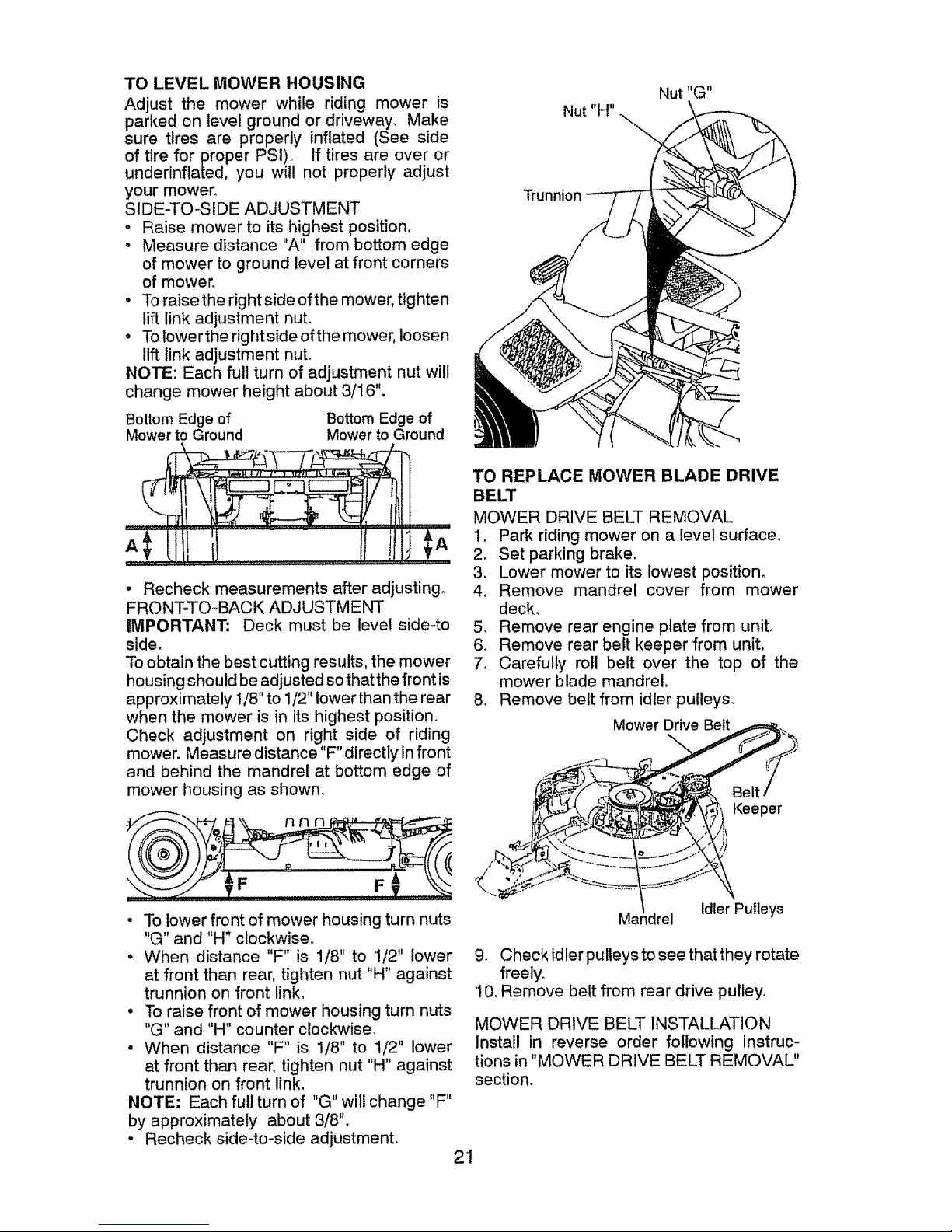
FRONT-TO-BACK ADJUSTMENT
IMPORTANT: Deck must be level side-to
side.
To obtain the best cutting results, the mower
housing should be adjusted so that the front is
approximately 1/8" to 1/2" lower than the rear
when the mower is in its highest position.
Check adjustment on right side of riding
mower. Measure distance "F" directly in front
and behind the mandrel at bottom edge of
mower housing as shown.
Trunnion
TO REPLACE MOWER BLADE DRIVE
BELT
MOWER DRIVE BELT REMOVAL
I. Park riding mower on a level surface.
2. Set parking brake.
3, Lower mower to its lowest position°
4, Remove mandrel cover from mower
deck,
5. Remove rear engine plate from uniL
6. Remove rear belt keeper from unit,
7_ Carefully roll belt over the top of the
mower blade mandrel,
& Remove belt from idler pulleys.
Mower Drive Belt
Keeper
• To lower front of mower housing turn nuts
"G" and "H" clockwise.
• When distance "F" is 1/8" to 1/2" lower
at front than rear, tighten nut "H" against
trunnion on front linko
• To raise front of mower housing turn nuts
"G" and "H" counter clockwise.
• When distance "F" is 1/8" to 1/2" lower
at front than rear, tighten nut "H" against
trunnion on front link.
NOTE= Each full turn of "G" will change "F"
by approximately about 3/8".
• Recheck side-to-side adjustment,
Idler Pulleys
9. Check idler pulleys to see that they rotate
freety_
10oRemove belt from rear drive pulley,
MOWER DRIVE BELT INSTALLATION
Install in reverse order following instruc-
tions in "MOWER DRIVE BELT REMOVAL"
section,
21
Page 22
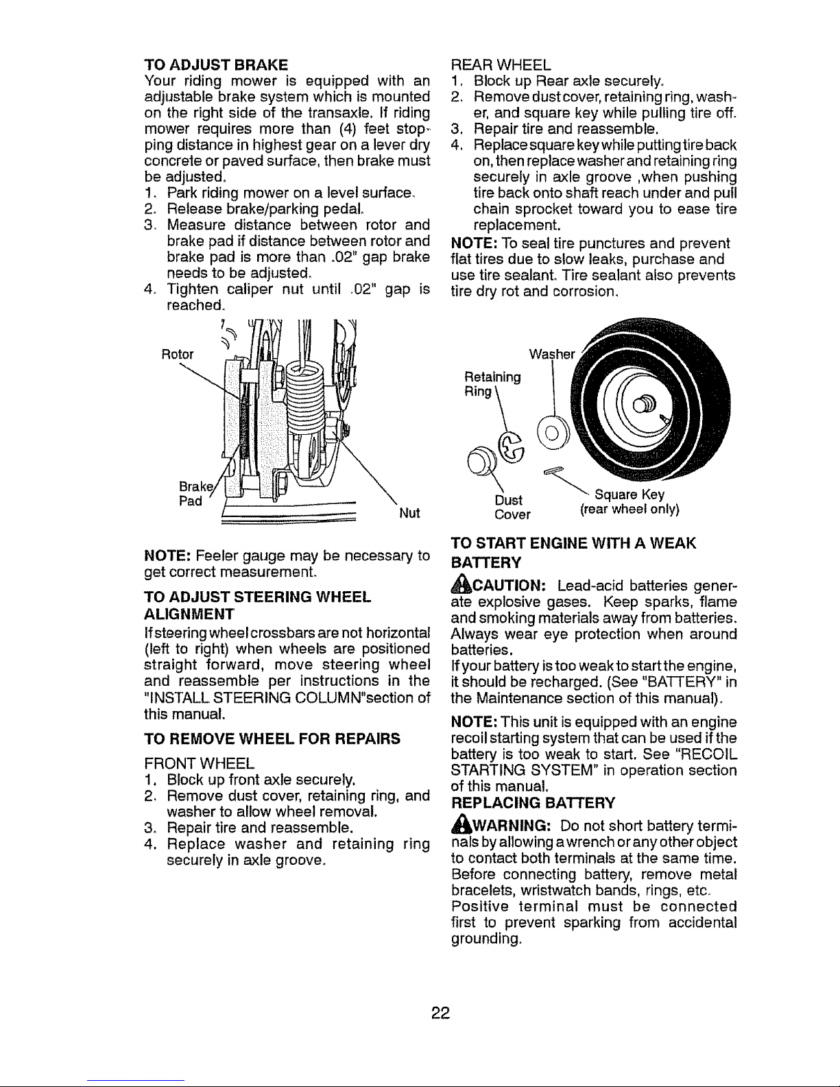
TO ADJUST BRAKE
Your riding mower is equipped with an
adjustable brake system which is mounted
on the right side of the transaxle, If riding
mower requires more than (4) feet stop_
ping distance in highest gear on a lever dry,
concrete or paved surface, then brake must
be adjusted°
1. Park riding mower on a level surfacer
2. Release brake/parking pedal.
3. Measure distance between rotor and
brake pad if distance between rotor and
brake pad is more than .02" gap brake
needs to be adjusted_
4_ Tighten caliper nut until .02" gap is
reached°
Rotor
Pad
Nut
NOTE: Feeler gauge may be necessary to
get correct measuremenL
TO ADJUST STEERING WHEEL
ALIGNMENT
If steering wheel crossbars are not horizontal
(left to right) when wheels are positioned
straight forward, move steering wheel
and reassemble per instructions in the
"INSTALL STEERING COLUMN"section of
this manual,
TO REMOVE WHEEL FOR REPAIRS
FRONT WHEEL
1. Block up front axle securely,
2, Remove dust cover, retaining ring, and
washer to allow wheel removal.
3_ Repair tire and reassemble.
4. Replace washer and retaining ring
securely in axle groove.
REAR WHEEL
1, Block up Rear axle securely,
2, Remove dust cover, retaining ring, wash-
er, and square key while pulling tire off.
3. Repair tire and reassemble.
4. Replacesquare keywhile puttingtire back
on, then replace washer and retaining ring
securely in axle groove ,when pushing
tire back onto shaft reach under and pu!l
chain sprocket toward you to ease tire
replacement.
NOTE: To seat tire punctures and prevent
flat tires due to stow leaks, purchase and
use tire sealant, Tire sealant also prevents
tire dry rot and corrosion.
Retaining
Ring _
Dust
Cover
_''", Square Key
(rear wheel only)
TO START ENGINE WITH A WEAK
BATTERY
_CAUTION: Lead-acid batteries gener-
ate explosive gases. Keep sparks, flame
and smoking materials away from batteries,
Always wear eye protection when around
batteries.
If your battery istoo weak to start the engine,
it should be recharged. (See "BATTERY" in
the Maintenance section of this manual).
NOTE: This unit is equipped with an engine
recoil starting system that can be used if the
battery is too weak to start. See "RECOIL
STARTING SYSTEM" in operation section
of this manual.
REPLACING BATTERY
_I_WARNING: Do not short battery termi-
nals by allowing awrench or any other object
to contact both terminals at the same time.
Before connecting battery, remove metal
bracelets, wristwatch bands, rings, etc,
Positive terminal must be connected
first to prevent sparking from accidental
grounding_
22
Page 23
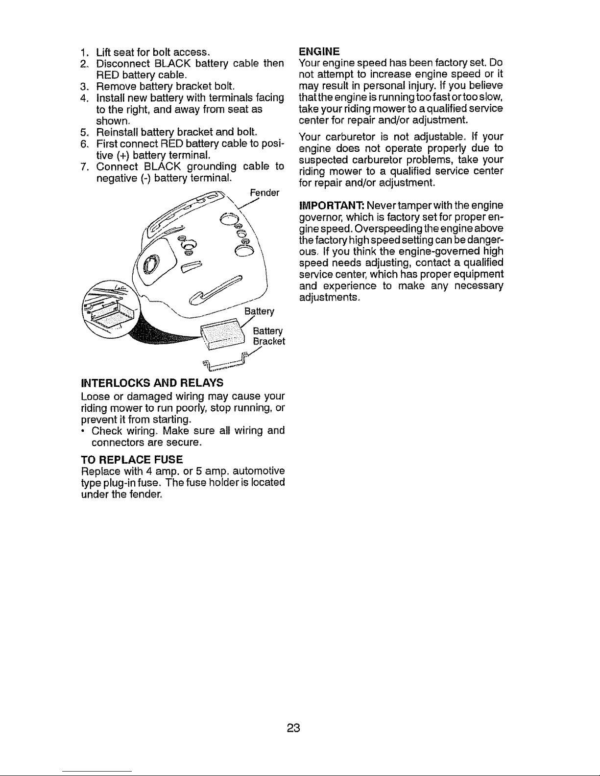
1. Lift seat for bolt access_
2_ Disconnect BLACK battery cable then
RED battery cable.
3. Remove batter,/bracket bolt,
4. Install new battery with terminals facing
to the right, and away from seat as
shown,
5, Reinstall battery bracket and bolto
6, First connect RED battery cable to posi-
tive (+) batter,/terminal,
7. Connect BLACK grounding cable to
negative (-) battery terminal
Fender
Battery
Battery
Bracket
INTERLOCKS AND RELAYS
Loose or damaged wiring may cause your
riding mower to run poorly, stop running, or
prevent it from starting.
• Check wiring_ Make sure all wiring and
connectors are secure°
TO REPLACE FUSE
Replace with 4 amp, or 5 amp. automotive
type plug-in fuse, The fuse holder is located
under the fender,
ENGINE
Your engine speed has been factory set, Do
not attempt to increase engine speed or it
may result in personal injury', tf you believe
that the engine is running too fast or too slow,
take your riding mower to a qualified service
center for repair and!or adjustment.
Your carburetor is not adjustable, ff your
engine does not operate properly due to
suspected carburetor problems, take your
riding mower to a qualified service center
for repair and/or adjustment°
IMPORTANT: Never tamper with the engine
governor, which is factory set for proper en-
gine speed. Overspeeding the engine above
the factory high speed setting can be danger-
ouso if you think the engine-governed high
speed needs adjusting, contact a qualified
service center, which has proper equipment
and experience to make any necessary
adjustments,
23
Page 24
Immediately prepare your riding mower for
storage at the end of the season or if the
riding mower will not be used for 30 days
or more.
_WARNING: Never store the riding mower
with gasoline in the tank inside a building
where fumes may reach an open flame or
spark. Aliowthe engine to cool before storing
in any enclosure.
MOWER
Remove deck from mower for winter stor-
age° When mower is to be stored for a
period of time, clean it thoroughly, remove
all dirt, grease, leaves, etc. Store in a clean,
dry area.
1, Clean entire riding mower (See"CLEAN-
ING" in the Maintenance section of this
manual),
2. Inspect and replace belt, if necessary
(See belt replacement instructions in the
Service and Adjustments section of this
manual),
3o Lubricate as shown in the Maintenance
section of this manual°
4. Be sure that all nuts, bolts and screws
are securely fastened. Inspect moving
parts for damage, breakage and wear°
Replace if necessary.
5, Touch up all rusted or chipped paint
surfaces; sand lightly before painting,
BATTERY
• Fully charge the battery for storage.
• If battery is removed from riding mower
for storage, do not store battery directly
on concrete or damp surfaces,
ENGINE
FUEL SYSTEM
IMPORTANT: It is important to prevent
gum deposits from forming in essential fuel
system parts such as carburetor, fue! hose,
or tank during storage. Also, alcohol blended
fuels (called gasohol or using ethanol or
methanol) can attract moisture which leads
to separation and formation of acids during
storage° Acidic gas can damage the fuel
system of an engine while in storage°
• Empty the fuel tank by starting the engine
and letting it run until the fuel lines and
carburetor are empty,
• Never use engine or carburetor cleaner
products in the fuel tank or permanent
damage may occur.
. Use fresh fuel next season,
NOTE: Fuel stabilizer is an acceptable al-
ternative in minimizing the formation of fuel
gum deposits during storage, Add stabilizer
to gasoline in fuel tank or storage container.
Always follow the mix ratio found on stabilizer
container. Run engine at least 10 minutes
after adding stabilizer to allow the stabilizer to
reach the carburetor. Do not empty the gas
tank and carburetor if using fuel stabilizer.
ENGINE OIL
Drain oil (with engine warm) and replace
with clean engine oil. (See "ENGINE" in the
Maintenance section of this manual).
CYLINDER(S)
1, Remove spark plug(s).
2. Pour one ounce of oil through spark plug
hole(s) into cylinder(s).
3. Turn ignition key to "START" position for
a few seconds to distribute oil.
4. Replace with new spark plug(s).
OTHER
• Do not store gasoline from one season to
another.
° Replaceyourgasolinecanifyourcan starts
to rust. Rust and/or dirt in your gasoline
will cause problems,
. Ifpossible, storeyourriding mowerindoors
and cover it to give protection from dust
and dirt,
• Cover your riding mower with a suitable
protective cover that does not retain mois-
ture. Do not use plastic. Plastic cannot
breathe which allows condensation to form
and will cause your riding mower to rust,
IMPORTANT: Never cover riding mower
while engine and exhaust areas are still
warm,
24
Page 25

TROUBLESHOOTING CHART:
PROBLEM CAUSE
Will not start I Out of fu
2 Badspal (plug
3 Dirty air iter+
4 Water in :uel,
Loose or damaged wiring
Engine v _lves out of adjustment
Dirty air
5
6
Hard to start 1
1
2
3
4
5
6
CORRECTION
Fill fuel tank.
Replace spark plugo
Clean/replace air filter.
Empty fuel tank and carburetor,
refill tank with fresh gasoline and
replace fuel filler,
Check all wiring
Contact a qualified service center°
Clean/replace air filter+ ........
2 Badspal <plug.
3 Weakor Jead battery.
4 Staieor+ +irtyfue!.
5 Loose ot damaged wiring.
6 Engine v dyes out of adjustment+
2
3
4
5
6
Replace spark plug+
Recharge or replace battery.
Empty fuel tank and refill tank
with fresh, clean gasoline+
Check all wiring.
Contact a qualified service center,
Engine will not
turn over
Engine clicks but
will not start
Loss of power
! Clutch/b+
2 Deck clu
3 Weak or
4 Blown fu
5 Corrode_
6 Loose o_
7 Faulty ig
B Faulty sc
9 Faultyop
1 'Weak or
2 Corrode_
3 Loose o!
4 Faulty sc
1
2
_ke pedal not depressed. 1
ch is engaged, 2
:lead battery_ 3
;e, 4
battery terminals, 5
damaged wiring 6
lition switch° 7
lenoid or starter. 8
.=ratorpresenceswitch(es) 9
:lead battery, 1
battery terminals, 2
damaged wiring. 3
lenoid or starter+ 4
Cutting too much grass/too fast+
Build+up of grass, leaves and
under mower,
Depress clutch/brake pedal.
Disengage deck clutch,
Recharge or replace battery.
Replace fuse.
Clean battery terminals,
Check all wiring+
Check/replace ignition switch°
Check/replace solenoid or starter,
Contact a qualified service center_
Clean battery terminals°
Check all wiring,
Check/replace solenoid or starter.,
Raise cutting height/reduce speed,
Clean underside of mower
housing,
3 Dirtyair filter-
4 Lowoil level/dirty oil,.
5 Faultyspark plug,
6 Staleordirty fuel
7 Water in fuel+
8 Spark ph wire loose
9 Dirty engine air screen/fins
10 Didylcloc ed muffler.
11 Loose or damaged wiring,
Clean/replace air filter°
Check oil level/change oil.
Clean®aporchangesparkplug.
Empty fuel tankand refilltank
withfresh,cleangasoline.
Empty fuel tankand carburetor,
refifi tankwithfresh gasoline,
Connect &tightenspark plug wire.
Clean engine airscreen/fins.
Clean/replace muffler,
Check all wiring,
Excessive vibration
12 Engine vaJves out of adjustment.
1 Worn, bent or loose blade,
2 Bent blaq mandrel.
3 Loose/d_ gad part(s),
Contact a qualified service center,
Replace blade, Tighten blade
boll
Contact a qualified service center,
Tighten loose part(s).
Replace damaged parts
25
Page 26

TROUBLESHOOTING CHART:
PROBLEM CAUSE
1 Faulty operator_safety presence
control system.
Engine continues to
run when operator
leaves seat with atta-
chment clutchengaged
Poor cut - uneven
cutting
Mower blade will
not rotate
Poor grass
discharge
Battery will not
charge
.oss of drive
tErng!nedle.s,'_he.n
aczor IS snlltea
into reverse
1
2
3
4
5
1
2
3
4
1
2
3
4
51
6
7
8
9
10
2j
3_
1
2
1
Worn, bent or loose blade.
Mower deck not level_
Buildup of grass, leaves, and trash
under mower.
Bent blade mandrel,
Clogged mower deck vent from
build-up of grass, leaves, and
trash around mandrel.
Obstruction in clutch mechanism,
Worn/damaged mower drive belt
Frozen idler pulley,
Frozen blade mandrel,
Travel speed too fast,
Wet grass,
_ower deck not level.
Low!uneven tire air pressure.
Worn, bent or loose blade.
Buildup of grass, leaves and
trash under mower_
Mower drive belt worn°
Blade improperly installed,
Improper blade used,
Clogged mower deck vent holes
from buildup of grass, leaves, and
trash around mandrels,,
Bad battery cell(s)o
Poor cable connections_
Faulty alternator°
Freewheel control in
"DISENGAGED" position°
Axle key missing
Reverse operation system (ROS)
is not "ON" while mower or other
attachment is engaged,
1
1
2
3
4
5
1
2
3
4
1
2
3
4
5
6
7
8
9
10
1
2
3
1
2
1
CORRECTION
Check wiring, switches and
connections_ If not corrected,
contact a qualified service center
Replace blade. Tighten blade bolt
Level mower deck
Clean underside of mower
housing
Contact a qualified service center
Clean around mandrels to
open vent holes
Remove obstruction,
Replace mower drive belt,
Replace idler pulley.
Contact a qualified service center.
Shift to slower speed,
Allow grass to dry' before mowing,
Level mower deck,
Check tires for proper PSI,
Replace/sharpen blade. Tighten
blade bolt.
Clean underside of mower
housing,
Replace mower drive belt,
Reinstall blade sharp edge down,
Replace with blade listed in
this manual.
Clean around mandrels to
open vent holes
Replace battery,,
Check/clean all connections.
Replace alternator,
Place freewheel control in
"ENGAGED" position,
!nstall axle key at rear wheel, See
'TO REMOVE WHEEL" in the
Service and Adjustments section.
Turn ignition key to ROS "ON"
position. See Operation section°
26
Page 27

SCHEMATIC
RIDING MOWER --CATALOG NO. 28600
_;:tfZt
PJ_)
BATTERY
FUSE-SA €_
FUSE-40A
SI'ARTER
ttliLAY STAR'rER
1........ i
) , , .,, !va'n,
__it, ', _-_ __IF_ : _ , O0
fCLb*i_ll OF7_, I................... I
rr
R_VFRSF. . _ _a:_ ...... : ; =::'::=."
NOT
._:.IN " _.|LORTIHGCOFINECTOR,
C_ |GNI'FK)N_'OUNIT @
SPARKPLUG
GAP
IEI)
C1h\R{]R,_O S¥_I"E;=,I otrlTt_ _,gVOI,T8 ?,C MIN _ lfi0n REM
;',MI'F'A:@3tg)O_t)kI (CIh)xR(lt_ILlfP¢'__:)d DISL:ONI,,IECTE{)}
DIODE '.............. ,
STATOR
IGNITION SWITCH
POSITION ClR_'urr "MAKE"
OFF NI+Cr_A1
RUN B+AI L÷A2
START B + S + At
SAFKFYSTART MODULE
vIEWED FROM MA'[[N'_ EIDE
WIRING INS ULATED CLIPS
NOTE: IF WIRING INSULATED CLIPS
WERE REMOVED FOR SERVICING OF
UNIT,THEY SHOULD BE RE-INSTAl.LED
TO PROPERi.Y SECURE YOUR WIRING
/i,
O
RENIOVABLE
CONNECHONS
@
NON-REMOVABLE
CONNECTIONS
27
Page 28

ELECTRICAL
RIDING MOWER --CATALOG NO, 28600
LRVI
10
9
/
8
i •
i i a i
F € i I
i I _. I I I 1
t i t s l !
t I a
i
s
t t t
I I t
I I •
. ÷
13\ . , •.
/ s !
t
!
._ _--_.- ,= ,
l '
'' _2 u ",
t ,
I i
| ,
# t t I
f I |i
I
I
/
3 4
2
7
28
Page 29

ELECTRICAL
RIDING MOWER--CATALOG NO. 28600
KEY PART
NO. NO.
t 423264
2 425416
3 193350
4 411934
5 433330
6 425937
7 160784
B 431542
9 109553X
10 176138
11 431646
12 192749
t3 428477
DESCRIPTION
BATTERY, 12V, 8AH
FOAM, POLYURETHANE
SWITCH, IGN, DLTA, P-IN, ROS
KEY, MOLDED
FUSE, 5A
FUSE, 40A
SWITCH, PLUNGER, NO, OLIVE
RELAY, 40A
SWITCH, INTLK,CL, MWR, GRY
SWITCH, INTERLOCK, NONC,GRAY
MODULE, STARTING, RECOIL, LRV
SWITCH, SEAT,DR ROS
HARNESS, 1GN, ELECTSTART, LRV
NOTE: All component dimensions given inU S. inches
! inch = 25.,4 mm
29
Page 30

CHASSIS
RiDiNG MOWER --CATALOG NO. 28600
_44
42
_26
30
Page 31

CHASSIS
RIDING MOWER ..-CATALOG NO. 28600
KEY PART
NO. NO. DESCRIPTION
1 428048 WELDMENT' CHASSIS
2 428247 SUPPORT, AXEL LH
3 428244 SUPPORT, AXEL RH
4 428346 SHIELD, TRANSAXLE FRONT
5 428110 BRACE, AXLE CROSS
6 428109 COVER, FRICTION DRIVE
7 428040 PLATE, ENGINE
8 428576 BRACKET, CHASSIS FRONT
9 428856 BRACKET, STEERING SUPPORT
10 195530 PAN, SEAT
11 174648X43I BRACKET, SWITCH MOUNTING
12 428248 BOOT, DUST
13 428251X665 COVER, FOOT REST
14 428250 STRUCTURE, FOOT REST
15 428249 SUPPORT, FOOT REST
t6 428241X665 FENDER, CONTROL
17 428348 GUARD, ENGINE
18 428047 ENGINE, (NON-CALIFORNIA) t2S907q 4t 1-B1
- _ 432389 ENGINE, (CALIFORNIA) 121S07-1415-F1
-- 435674 ENGINE, (CANADA) 12S907-1463-B1
19 428986 KEEPER, BELT
20 428048 BRACKET, BATTERY
21 429815 LEVER, SWITCH
22 428826 DECK CLUTCH ASM
23 149846 KNOB
24 416358 SCREW, NO. 10
25 72140424 BOLT, CARRIAGE 1/4-20 X3
26 73510400 NUT, 1/4-20
27 430087 SPACER, ENGINE
28 428301 DISC, FRICTION ASM
29 430817 BOLT, SCKT HD 3/8-24 X ! 25
30 430470 BEARING
31 430469 SPACER, NEUTRAL
32 150406 BOLT,3/8-16 X 280
33 124181X SPRING, SEAl"
34 121250X SPRING
35 72050412 BOLT, 114-20X t 1/2
36 !27018X BOLT, SHOULDER
37 19171912 WASHER, t7/32 X ! 3/16
38 !66369 KNOB, SEAT
39 134300 SPACER
40 12!248X BUSHING, NYLON SNAP
41 !23976X NUT' LOCK
42 171852 BOLT, 5/16-18 SHOULDER
43 73800500 NUT, 51164 8
44 428243 SEAT
45 17000512 BOLT,5/t6-18 X 3/4
48 17490508 BOLT,5/I6-18 X 1/2
47 86777 SCREW,
48 408981 BEARING, FLANGE, BALL
49 17060516 SCREW, 5/16-!8 Xt
50 165492 BOLT,SHOULDER, 5/16-18 x ,561
NOTE: All component dimensions given in UoS inches
1 inch = 25.4 mm
31
Page 32

DRIVE
R|DING MOWER --CATALOG NO, 28600
32
Page 33

DRIVE
RIDING MOWER--CATALOG NO, 28600
KEY
NO,
1
2
3
4
5
6
7
8
lO
11
12
13
14
15
16
17
18
19
2o
21
22
23
24
25
26
27
28
29
30
31
32
33
34
35
36
37
38
PART
NO.
436144
428268X613
!21748X
12000001
123583X
427939
428069
427873
12100009
428876
1370H
430645
430845
427946
9159R
427926
428106
424759
¢30870
427997
428077
428076
431374
427995
428303
429816
429053
428302
174840
183900
429055
428464
428461
428462
196492X428
72110406
73800400
165492
KEY PART
DESCRIPTION NO. NO.
SERVICE, TRANSAXLE 39 74780412
WHEEL ASM (REAR) 40 10040400
WASHER, 16 CA. 4! 19091210
E-CLIP 42 166002
KEY. SQUARE 43 73680400
WELDMENT. DRIVE AXLE 45 17490436
CHAIN DRIVE 46 19091016
SPROCKET. 9 TOOTH SPLINED 47 17490420
RING, SNAP 48 430249
DIFFERENTIAL ASM 49 430245
WASHER, THRUST 50 428021
CHAIN, PRIMARY DRIVE 51 430247
BUSHING 52 428078
BRACKEI', CARRIER 53 77010810
BEARING ASM 54 428019
SHAFT INPUT 55 428017
WHEEL, FRICTION A5M 56 435253
ARM, SHIFT 57 428016
ROD, BYPASS 58 4497H
BRACE, CARRIER, REAR 59 17490508
SPRING, CARRIER 60 428460
SPRING, BRAKE 61 427945
SPRING, BYPASS 62 429678
BRACE CARRIER BOX 63 77100612
LINK, SHIFT 64 76020208
ARM. CLUTCH 65 429325
WELDMENT SHIFT LEVER 66 429694
SUPPORT, SHIFT LEVER 67 429693
WASHER, NYLON 68 17490406
HUB SHIFT LEVER 69 428070
SPACER, NYLON 70 17000512
MNTG BRKT, SHIFT ARM 71
BRACKE_, SHIFTER FLEX 72
TUBE SHIFT ARM 73
GRIP, HANDLE
BOLT, CARRIAGE - 114-20 X 3/4
NUT NYLON LOCK 1t4-20
BOLT, SHOULDER
DESCRIPTION
BOLT, 1/4-20 X 3/4
WASHER, LOCK
WASHER FLAT
WASHER, SERRATED
NUT, CROWN LOCK 114-20
SCREW 1/4-20 X 2 114
WASHER
SCREW, 1/4-20 X t I/2
PLATE BRAKE ANTI - ROTATE
SPRING, BRAKE RETURN
ARM, BRAKE
SPACER RETURN
CALIPER, BRAKE ASM
PiN, DOWEL t/4
PLATE, BRAKE PAD
PUCK BRAKE
ROTOR, BRAKE
CAP, BRAKE CALIPER
PIN, RETAINER
BOLT, 5/16-16 X 112
CABLE, BRAKE
WELDMENT, PEDAL
ROD, PARKING BRAKE
PIN, 25 X .75 CLEVIS
PIN, t/16 DIA. COTTER
BRACKET BRAKE SUPPORT
COVER, PEDAL
COVER, BRAKE PEDAL
SCREW, 1/4-20 X 3/8
BRAKE CABLE MOUNT
BOLT, 5/!6-18 X 3/4
I04757X613 CAP HUB AXLE
12000002 E RING #5133-62
429519 SPROCKET IITOOTH SPLINED
NOTE: All companent dimensions given in U,S. inches
1 inch = 25,4 mm
33
Page 34

RiDiNG MOWER --CATALOG NO. 28600
23
1-/
LRV_Steeringj r2
34
Page 35

RIDING MOWER --CATALOG NO. 28600
KEY PART
NO. NO.
1 428269)(613
2 1200000t
3 188987
4 t21749X
5 428034
6 6266H
7 3366R
8 421076
9 19131414
10 428057
1! 428035
12 428036
13 74780524
14 19131016
15 73800500
16 428044
17 428252
18 195227
19 17000512
20 428045
2I 428347
22 428213
23 186737
24 19183812
25 73940800
26 414851 X418
27 414852X418
28 199849
29 428033
30 104757X613
DESCRIPTION
WHEEL ASM (FRONT)
E_LIP
WASHER, HARDENED
WASHER, 1/4 X 3/4
SPINDLE, RH
WASHER, HARDENED THRUST
BUSHING, STEERING COLUMN
PIN, 5/64 X 3/4 COTTER
WASHER
WELDMENT, IJWR STRG SHAFT
LINK, STRNG LH
LINK, STRNG RH
BOLT, 5/16-18 X 1 1/2
WASHER
NUT, 5/16-18
BUSHING, STEERING SNAP
SUPPORT, UPPER STEERING
BUSHING, UPPER STEERING
BOLT,5/16-18 X 3/4
CLIP, RETAINER SPRING
COVER, STEERING COLUMN
SHAFt, STEERING
ADAPTER, STEERING WHEEL
WASHER, 9/16 X 2 3/8 12 GA,
NUT;,JAM LOCK 1/2-20
WHEEL, STEERING
CAP,STEERING WHEEL
CLIP,RETAINER SPRING
SPINDLE, LH
CAP,HUB, AXLE
NOTE: All component dimensions given in U,S. inches
I inch = 25 4 mm
35
Page 36

MOWER DECK
RIDING MOWER --CATALOG NO. 28600
12
LRV_eck 1_r3
36
Page 37

MOWER DECK
RIDING MOWER--CATALOG NO, 28600
KEY PART
NO. NO. DESCRIPTION
1 428193 DECK, 26"
2 192870 MANDREL ASM
3 432520 KEEPER, BELT
4 432594 PULLEY, MANDREL
5 428578 BELT
6 428242 COVER, MANDREL
7 429395 LIFT ASM, DECK
8 429195 LINK, DECK LIFT
9 429397 LINK, ADJUSTABLE
10 428146 DEFLECTOR
11 428968 SUPPORT, DEFLECTOR
12 131491 ROD, HINGE
13 197026 SPRING, TORSION
14 418863 ARM, MOWER SUPPORT
15 73900500 NUT, LOCK
16 t 95161 STUD
17 19191912 WASHER
18 194209 PIN
19 196539 BOLT, SHOULDER
20 194208 PIN
21 19171912 WASHER, 17/32 X 1 3/16
22 429350 LINK, DECK
23 73930600 NUT, LCK 3/8-16
24 429531 SPRING, DECK
25 4497H PIN
26 187690 SPACER, MANDREL
27 173984 BOLT, MANDREL
28 400234 NUT, LOCK
29 42850D BLADE
30 193003 BOLT, BLADE
31 193197 PULLEY, IDLER
32 141043 GUARD, IDLER
33 193414 KEEPER, BELT IDLER
34 72110612 BOLT, 3/8q6 X 1 1/2
35 199470 ARM, BRAKE
36 !37729 SCREW, I/4_20 X 5/8
37 73900600 NUT, 3/8-16 FLANGE
38 428435 ARM, IDLER
39 17490508 BOLT, 5/16-18 X 1/2
40 19171616 WASHER, 16 GA.
41 105304)< CAR SLEEVE
42 110452X NUT, PUSH
43 125631X GRIP, HANDLE
44 429401 PLUNGER
45 105767 PIN
NOTE: All component dimensions given in US. inches
t inch = 25.4 mm
37
Page 38

DECALS
RIDING MOWER --CATALOG NO. 28600
2
4
KEY PART
NO. NO.
1 430588
2 433596
3 425113
4 430589
*5 424102
6 435346
-- 432479
-- 436518
-- 436520
-- 436519
DESCRIPTION
DECAL, STEERING WHEEL
DECAL, V-BELT SCH 30"
DECAL, WARN. DEFLECT/CTFGR
DECAL, DECK/DEFLECTOR
DECAL, SPARK ARRESTOR
DECAL, WARN ING
DECAL, BYPASS
MANUAL OPERATOR ENGLISH
MANUAL OPERATOR FRENCH
MANUAL OPERATOR SPANISH
NOTE: All componentdimensionsgiven inU_S, inches
1 inch = 254 mm
38 *California models only,
Page 39

!
I
!
i
/
/
I
/
I
/
/
/
/
/
/
/
/
/
/
0
C
m
m
0
C
0
m
0
(n
ml
i--'
0
=0
m
u_
0
m
0
m
-4
m
0
Z
39
Page 40

PARTS AND SERVICE
This product has been expertly engineered and carefully manufactured to rigid quality standards° As with all
mechanical products some adjustments or part replacement may be necessary during the life of your unit
For Parts and service, conlact our authorized distributor: call 1-B00-849-1297
- For replacement parts, have available the following information:
a Model Number/Manufacturer's ID. Number
b Description of part
For Technical Assistance: call 1-B00-B29-5BB6
For a Parts Manual, gDto our website: www.weedeater corn
HOP provides parts and service through its authorized distributors and dealers; therefore,
all requests for parts and service should bedirected toyour local dealer(s). The philosophy
of HOP is to continually Improve all of Its products. Ifthe operating characteristics or the
appearance of your product differs from those described in this Manual, please contact
your local dealer for updated information and assistance.
Page 41

Manual del Operader
CORTADORA DE CESPED DE 26"
DESCARGA LATERAL
ARRANQUE ELECTRICO
Ndmero de Cat, logo
28600 IMPORTANTE:
Lea.y siga todas la Reglas e
lnstrucciones de Seguridad
antes de operar este equipo.
Patents Pending
Page 42

Garantia ................................................... 2
Reglas de seguridad ............................... 3
Especificaciones del producto ................ 6
Ensam blado/Preoperacifn ..................... 7
Operaci6n ............................................... 10
Programa de mantenimiento ................ 16
Mantenimiento ...................................... 16
Servicio y Ajustes ................................. 20
Almacenamiento ....................................24
Solucifn de problemas ......................... 25
Partes de reparaci6n ............................ 27
GARANTiA LnMnTADA
E! Fabflcanlegaranllza a! comprado[consumidor original qua este preducto esl& fabricade libra de detectos en los mater_ales
y la manodeobra Per un periodede des (2) afos a par!it de la fecha de compra per parle del compradorconsumldor original
repararemeso reemplazaremos,a nuestraelecci6n, sin cargo per los par!as o la mane de obra incurrida al reempiazar partes
cualquiera de los par!as qua detarminemos que liana defectos debido a los materiales o la mane de obra Esta garantfa estz_
su)eta a losslguienles restriccionesy exclustones.
1- Esla garantiano aplica a! motor, la baterfa (excepto conforme se indfca en seguida) o los componenles de los mismos
Perfavor consultela garantla del fabricante correspondiente para estos elementes
2. Loscargosde transporteper el movimiento de cualquier equipo motorizado o acoplamienlo son responsabiiidad del com-
prador. Los cargosde transpode per las partes enviades pare reemplazo baio asia garantfa deben set pagodas per el
comprador,a manes qua et fabricante sol!cite esa devolucibn
3 Ga_anlia de la baterla: Para productosequipados con bateria, raemplazaremos sin cargoalguno pare ustedcuaiquier
be!erie qua determInemos qua su fabricaci6n es defectuosa, duranle los prtmeros novenla (98) dies posteriores ala
compra..Despu_s de noventa (90) dfas. tntercambiaremos la be!erie con un cargo pare ustedde t112 del precto de una
nueva be!erie per coda rues complete a parltr de la fecha de la venta original Se debe dar mantenimtenie ala baterfa de
acuardo con |as instmcciones pfovistas,
4- La garantia no aplica a ningt_nproductoque se use con prop6sitos de renta o cemerciales
5- Esta garantta apfica t3nicamente a pfoductosqua se hen armada, aJuslado, operado y mantenido de acuerdo con los
tnstrucciones provistas. Esta garantfano aplica a ningt]n producloqua se haya some!idaa alteraciones, use incorrecte.
abuse, armada o insta!aci6n lncerrecla, doses en la entrega oal desgesle normal del producto.
6. Bclusiones; Se exclwen de esta garanfla los clntes, cuchitlas, adapladeres de cuchiila, eldesgeste normal, los ajustes
normales, los artfculos de forte!erie esl-¢ndaryel mantenimiento normal
7. En case de qua tonga una reclamactbn b_o asia garantia, debe devolver el productoa un distribuldor de servicioautod-
zado.
En case de qua tonga preguntas con respecto a esta garantia comunfquese con:
HOP
Deplo de Servicio al Cliente de Productos pare
Extedores
9335 Harris Corners Parkway
Chattel!e, NC 28269 USA
En Canad,_ centacle a;
HOP
5855 Terrt Fax Way
Mississauga. Ontario
L5V 3E4
y propomione el n_mem de modelo, elnrbmerode serie y lafecha de compradel producto,asl come el nombray la direccibn
del disldbuidor autorizado donde rue comprado
ESTA GARANTtA NO SE APLICA A DANES INCIDENTALEB O CONSECUENCIALES Y CUALQUIER GARANT_'A IMPLJ-
CITA SE LIMITA A LOS MISMOS PERiODOS ESTIPULADQS EN ESTE DOCUMENTO PARA NUESTRAS GARANTiAS
EXPRESAS Algunas reglonesno permiten la limilaci6n de dot=usconsecuenciales o restdcciones sabre la duracibn de una
garantia tmplictta, de mode qua los restricclenes e exclusiones artier!orespueden no aplicarseen su case Esta garantia le
otorgaderechoslegalesespecificosy ustedpuede lenerot_osderechesquevat{ande un lugaraotro
Esta es una garantta limtiada dentro de! stgnificado de ese I_rmino seg,3nto define la Ley Magnuson-Mess de 1975
2
Page 43

_PELIGRO: Esta Maquina cortadora es capaz de amputar las manosy los pies y de lanzar
objetos, si no se observan las Instrucciones de seguridad siguientes se pueden producir
lesiones graves o la muerte.
Con el fin de prevenir un arranque acci-
dental cuando configure, transporte, ajuste
o repare la m&quina, siempre desconecte el
cable de ta bujia y colcque el cable donde no
pueda entrar en contacto con la bujia.
_lb No descienda por una colina en neutral,
pues puede perder et control de la cortadora
de c_sped,
Et escape del motor, algunas de sus
partes y ciertos componentes det vehicuto
contienen o emiten productos quimicos de
los que se sabe en el Estado de California
que causan c&ncer y defectos de nacimiento
u otros daSos reproductivos.
Esta unidad no es para remolcar ni para
usarse con pesas para ruedas, Use s61o
accesorios disefiados especificamente para
esta cortadora de c_sped,
Los postes, las terminales y los acce-
sorios relacionados de la bateria contienen
plomo y compuestos de plomo, productos
quimicos de los que se sabe en el Estado de
California que causan c&ncer y defectos de
nacimiento u otros daSos reproductivos.
I. OPERAC|ON GENERAL
. Lea, entienda y siga todas las instruccio-
nes sobre la m&quina en et manual antes
de comenzar,
• Nocoloque las manos ni los pies cercade
las partes giratorias ni debajo de la m&-
quina. Mant_ngase alejado de la abertura
de descarga en todo momento.
• $6to permita que los aduttos responsa-
hies, que esten familiarizados con las
instrucciones, operen la m&quina,
• Libere el &rea de objetos como piedras,
juguetes, cables, etc. pues podrian atra-
parse y tanzarse con la cuchill&
• AsegSrese de que el &rea est_ libre de
curiosos antes de operar la m&quin&
Detenga ta m&quina si alguien entra en
el &rea.
• Nuncatransporte pasajeros.
• No corte en reversa, a menos que sea
absolutamente necesario. Siempre mire
hacia abajo y hacia atr&s antes y cuando
vaya en reversa.
• Nunca dirija el material que se descarga
hacia nadie, Evite descargar el material
contra una pared u otra obstrucci6n. E!
material puede rebotar hacia el operador.
Detenga la cuchilta cuando cruce por
superficies con grava_
• No maneje la maquina si no tiene el co-
lector de c_sped compteto, la canaleta de
descarga u otros dispositivos de seguridad
en su lugar y en funcionamiento,
• Desacetere antes de dar la vuelta.
• Nuncadeje la m&quina en funcionamiento
sin vigilar, Siempre detenga la cuchilla,
active el freno de estacionamiento, de-
tenga el motor y retire la Ilave antes de
descender.
° Desactive la cuchilla cuando no est6 cor-
tando c6sped. Apague el motor y espere
hasta que todas las partes se detengan
por completo antes de limpiar la m&quina,
retirar el colector de c6sped o destapar la
canaleta de descarga,
• Opere la maquina unicamente durante et
dia o con buena luz artificial,
• No opere la m&quina mientras est_ bajo
la inftuencia de alcohol o droga&
. Est_ pendiente del tr&fico cuando opere
la maquina cerca de caminos o al cruzar-
los,
• Tenga cuidado extremo cuando cargue
o descargue la m&quina de un trailer o
cami6n.
. Use siempre protecci6n ocular cuando
opere la maqulna.
. Los datos indican que los operadores de
60 6 m&s aBos de edad entran en un alto
porcentaje de lesiones retacionadas con
cortadoras de c6sped, Estos operadores
deben evaluar su habilidad para operar la
cortadora de c_sped en forma suficien-
temente segura como para protegerse a
si mismos y a los demas de una [esi6n
grave.
• Mantenga la m&quina libre de cualquier
acumulaci6n de c_sped, hojas u otra ba-
sura, pues podrian entrar en contacto con
el escape caliente y/o las partes del motor
y quemarse. No permitaque la ptataforma
de la cortadora de cesped levante hojas u
otra basura que pueda causar acumulacio-
nes, Limpie cualquier derrame de aceite o
combustible antes de operar o almacenar
la m&quina. Permita que la m&quina se
enfrie antes de atmacenarta,
3
Page 44

il. OPERACION EN PENDIENTES
Las pendientes son un factor principal que
se relaciona con la p6rdida de control y!os
accidentes de volcaduras, Io que puede dar
come resultado una tesi6n grave o la muer-
te. La operaciSn en todas las pendientes
requiere tener precauciones extras. Si usted
no puede retroceder de una pendiente o si
se siente inc6modo en ta pendiente, no la
pode.
• Pode las pendientes hacia arriba y hacia
abajo (a t5 ° come m&ximo), no de un lade
a otroo
• Tenga cuidado con los hoyos, surcos,
protuberancias, piedras y otros objetos
ocultos. El terreno disparejo podria
votcar la maquina_ El c6sped alto puede
esconder los obst&culos.
• Elija unavelocidad terrestre baja de mode
que no tenga que detenerse o girar mien-
tras est6 en la pendiente.
• No corte et c6sped h_medo, Las Ilantas
pueden perder su tracciSn.
. Mantenga siempre la m&quina en una
velocidad cuando baje per las pendienteso
No cambie a neutral ni vaya en punto
muerto hacia abajo en una colina,
• Si la m&quina se para mientras sube per
una colina, desactive la cuchilla, cambie
a reversa y baje despacio,
• Evite arrancar, parar o girar en una pen-
dienteo Si las Ilantas pierden su tracci6n,
desactive la cuchilta y proceda con lentitud
en linea recta hacia abajo per la pendien-
te,
i Mantenga todo el movimiento lento y
gradual sobre las pendientes. No haga
cambios repentinos de velocidad o direc-
ciSn, pues podda causar que la m&quina
se vuelque.
Tenga cuidaod extreme mientras
opera la m&quina con colectores de
c6sped u otros accesorios; pueden
afectar la estabilidad de la m&quina.
• No la use sobre pendientes pronuncia-
das.
. No intente estabilizar la m&quina poniendo
el pie en el sueloo
• No corte cerca de declives, zanjas o terra-
plenes. La m6_quina podda volcarse de
repente si una rueda pasa sobre la orilla
o si la orilta termina en un hoyo.
ill. NINES
Pueden ocurrir accidentes tr&gicos si el
operador no est& alerta ante ta presencia
de niAos, Con frecuencia los niSos se
sienten atraidos per la m&quina y la actM-
dad de corte de cespedo Nunca de per un
hecho que los niAos permanecer&n donde
usted los vie per _ltima vez.
• Mantenga a los nir_os alejados det &rea
de certe y bajo la supervision de un adulto
responsable a parte del operador.
• Est6 alertay apague la m&quina si un niAo
entra en el area.
• Antes y mientras avance en reversa, mire
hacia atr&s y hacia abajo per si hay nir_os
presenteso
• Nunca Ileve niAos arriba de la m&quina, in-
ctuso cuando la cuchilla est6 desactivad&
Pueden caerse y lesionarse gravemente
o intefferir con la operacion segura de la
m&quina. Los niAos a quienes se les da
una vuelta en la maquina pueden aparecer
de repente en el &rea de corte para otra
vueita y ser atropetlados o gotpeados con
la m&quina.
• Nunca permita que los niAos operen la
s .
maqutna.
• Tenga cuidado extreme al acercarse afas
curvas sin visibilidad, arbustos, &rboles
u otros objetos que puedan bloquear su
vision e impedir observar a un n_t_oo
IV. SERMIClO
MANEJO SEGURO DE LA GASO-
LINA
Para evitar una lesi6n personal o un daf!o
en la propiedad, tenga cuidado extreme al
manejar la gasolina. La gasolina es extre-
madamente inflamable y los vapores son
explosives,
• Apague los cigarrillos, habanos, pipas y
otras fuentes de ignici6n.
• Use sSIo un recipiente de gasolina apro-
bade.
° Nunca retire et tap6n de la gasolina ni
agregue combustible con el motor en
func)onamiento, Permita ClUeel motor se
enfne antes de volver a Ilenar et tanque
de combustible.
• Nunca !lene la m&quina de combustible
en interioreso
4
Page 45

° Nunca almacene la m&quina o et reci-
piente de combustible donde haya una
flama abierta, chispa o una luz de piloto
como ta de un calentador de agua u otros
aparatos,
° Nunca Ilene los recipientes adentro de
un vehiculo o en un camiSn o trailer con
forro de pt&stico. Coloclue siempre los re-
cipientes en et suelo y lejos de su vehfculo
durante et itenado.
• Retire et equipo que funciona con gasolina
del camiSn o trailer y rell_nelo en el suelo,
Si esto no es posible, entonces rellene este
equipo con un recipiente port&til, en lugar
de hacerlo directamente con ta boquilla
del dispensador de gasolina.
° Mantenga la boquilta en contacto con el
borde deltanque o recipiente de combustF
ble abri_ndolo en todo momento hasta que
el llenado de combustible est_ completo.
No use un dispositivo que mantenga
abierta ta boquilla,
° Si el combustible se derrama sobre la
ropa, c&mbiesela de inmediato,
° Nunca Ilene de m_s el tanque de com-
bustible, Vuelva a colocar el tap6n de la
gasolina y apri6telo bien.
SERVICIO GENERAL
• Nunca opere la m&quina en un &rea ce-
rrada.
, Mantenga todas las tuercas y pernos
apretados para asegurarse de que el
equipo se encuentra en condiciones de
trabajo seguras°
° Nunca manipute los dispositivos de segu-
ridad, Revise con regularidad que operen
bien.
, Mantenga !a m&quina libre de cualquier
acumulacion de cesped, hojas u otra
basur& Limpie los derrames de aceite
o combustible y retire cualquier basura
que contenga combustible. Permita que
ta maquina se enfrie antes de almacenar-
la.
• Si usted golpea un objeto extraflo, det_n-
gase e inspeccione la m&quina. Rep&rela,
de ser necesario, antes de votver a em-
pezar.
• Nunca haga ajustes o reparaciones con
el motor en funcionamiento_
° Revise los componentes del colector de
c_sped y la canaleta de descarga con
frecuenciay sustituya con repuestos
recomendados por el fabricante cuando
sea necesario.
• Lacuchillade lacortadorade c6sped tiene
filo. Envuelva la cuchilla o use guantes y
teng.a .precaucion extrema cuando les d_
ser¢IClO.
• Revise ta operaciSn del freno con fie-
cuencia, Ajuste y d_ servicio segt_n sea
necesarioo
. Conserve o cambie las etiquetas de
seguridad e instrucciones segl]n sea
necesarlo,
. AsegQrese de que el &tea est_ libre de
curiosos antes de operar la m&quina.
Detenga ta m_.quina si alguien entra en
el &rea.
, Nuncatransporte pasajeros.
, No corte en reversa, a menos que sea
absolutamente necesario. Siempre mire
hacia abajo y hacia atr&s antes y cuando
vaya en revers&
5
Page 46

Capacidad de 1_2 cuartos
gasoline y Tipo: Regular sin plomo
Tipo de aceite SAE 30 (per encima
(APt_SG-SL): de los 32°F 5 0°C)
SAE 51N-30 (per debajo
de los 32°F 6 0°C)
Capacidad de aceite: 20 onzas
Bujia: Champion RC12YC
(Espacio: .030")
Velocidad terrestre
Hacia adelante: 0-4 mph (0-6.5 kph)
Reversa: 0-I mph (0-! .6 kph)
Torque del perno 45 - 55 pies/Libras).
de la cuchilla:
RESPONSABIILIDADES DEL
CLIENTE
• Lea y observe las reglas de seguridado
• Siga un programa regular al darle mante-
nimiento, cuidados y use a su cortadora
de c6sped_
. Siga las instrucciones de las secciones
de "Mantenimiento" y 'Aimacenamiento"
de este manual del propietario,
_DVERTENCIA; Esta cortadora de
c6sped est& equipada con un motor de
combustion interne y no se debe usar en
o cerca de terrenos cubiertos de bosques
sin mejoras, cubiertos de arbustos o cu-
biertos de pastes, a menos que el sistema
de escape del motor est_ equipado con un
parachispas que cumpla con las leyes loca-
les o estatales aplicabtes (de haberlas), Si
se usa un parachispas, el operador deber&
darle mantenimiento en un orden de trabajo
efectivo_
En el estado de California, tas leyes exigen
el use de un parachispas (Secci6n 4442 del
C6digo de Recursos PQblicos de California).
Otros estados pueden tener leyes similares,
En los terrenos federales se aptican las leyes
federales. Se puede obtener un parachispas
para el silenciador a trav6s del centre de
servicio autorizado m&s cercano,
tnserte det volante
(1) Pasador
Cubierta de direcci6n
(1) Arandela pla_nagrande
@
Volante (1) Contratuerca 1/2-20
© ®
(1) Arandela plana 5/t6 (1) Conlratuerca 5/I6-18
Adaptador de! volante (t) Perno hexagonal
5/16-18 x 1 1/2
Cubierta del
eje de direcci6n
Eia de
direcci6n
Asiento
(1) Arandela
(1) Perilla
(2) LIave
Hoja de inclinaci6n
6
Page 47

Su nueva cortadora de c6sped se ha ensamblado en la f&brica con excepci6n de aquellas
p,artes que se dejan sin ensamblar para el envJo_ Pare asegurar la operaci6n segura y correcta
Lie ta cortadora de c6sped todas las partes y la ferreteria que usted ensambte se deaen
apretar bien_ Use las herram entas correctas necesarias pare asegurar un ajuste aprop ado.
HERRAMIENTAS NECESARIAS
PARA EL ENSAMBLADO
El ensamblado ser& m&s simple si cuenta
con un conjunto de llaves de cubo, Los
tamaSos de Ilave est&ndar que necesita se
indican en seguida_
(1) Llave de 3/4"
(1) Llave de I/2"
(1) Herramienta de cuchilla
(1) calibrador de presi6n pare Ilantas
Cuando se menciona la derecha o la
izquierda en este manual, esto significa
cuando usted se encuentra en la posicion
de operaci6n (sentacto al volante),
RETIRO DE LA CORTADORA DE,
CESPED DE LA CAJA DE CARTON
DESEMPACADO DE LA CAJA DE CAR-
TON
!. Corte las lineas punteactas de tos cuatro
paneles de la caja de cartSn. Retire la
caja de cart6n y el marco superior como
una sola pieza.
2. Retire los materiales de empaque de la
cortadora de c6sped.
NOTA: $61o corte la caja de cart6n con una
herramienta de cuchilta corta pues una de
cuchitla larga o una sierra pueden pincher
las Ilantas de la unidad,
COMO CONFIGURAR SU
CORTADORA DE OF_SPED
INSTALACION DE COLUMNA DE
DIRECCION
1. Inserte el eje de direcci6n en el montaje
y apriete blen con el perno, la arandela
y la tuerca provistas°
2_ Inserte el pasadoren el orificio del eje de
alreoclon,
3, Deslice la cubierta de pl&stico sobre et
eje de direcci6n y en su posici6n,
de direcci6n
.Cubierta de
4, De,slice la cubierta de espuma deprotec-
c_o.ndel eje de direcci6n sobre el eje,
5.._oloque las ruea.as, delanteras de la cor-
taaora ae cesp.ea ae modo .clue apunten
en linea recta hacia adelanteo
,, Cubierta de
Eje de direcci6n,,._ \
6_ Retire el adaptador del volante y deslice
el adaptador sobre el eje de direcciSn.
7. Presione elvolante en su posici6n sobre
el eje, instale la arandela grande y apriete
bien la tuercao
8, Coloque bien et inserto del volante en el
centro del volante,
INSTALAClON DEL ASIENTO
1, Gire el asiento hacia arriba y retirefo del
empaque de cartSn. Retire el empaque
de cert6n y des_chelo.
2. Coloque el asiento en la table del asien-
to de manera que el perno de reborde
est6 colocado sobre el orificio ranurado
grande de la tabla.
3. Presione hacia abajo el asiento para
colocar el perno de reborde en la ranura
y jale el asiento hacia la parte posterior
de la cortadora de c6sped,
Asiento
7
Pemo de
reborde
Page 48

4_
Gire el asiento y la tabla hacia adelante y
ensamble la perilla de ajuste y la arandela
plana sin apretar, No apriete,
Arandeta plana __
Perilla dieajuste g
5, Baje e! asiento a la posici6n de operaci6n
si_ntese sobre 61.
6. Deslice et asiento hasta que logre una
posici6n c6moda, Io que le permitir_,
presionar el pedal det embrague/freno
hasta el fondo°
7. Retiresedelasientosin moversu posici6n
ajustada_
8. Eleve el asiento y apriete bien la peri!la
de ajuste.
REVISE LA BATERIA
Aseg_rese de que la bateria est_ bien
sujetada, y que todos los cables est6n
bien conectadoso
• La bateria est& ubicada debajo del
asiento.
• La bateria se ha cargado pot completo
en la f&brica antes de su instalaci6n.
Asiento
\
Bateria
NOTA: Ahora puede sacar la cortadora de
c_sped de la tarima_ Observe las siguientes
instrucciones apropiadas para retirar la
cortadora de c_sped de la tarima.
e_n ADVERTENCIA: Antes de empezar, lea,
ienda y siga todas las instrucciones de
la secci6n de Operaci6n de este manual.
Aseg_rese de que la cortadora de c_,sped
est_ en un &rea bien ventilada. AsegQrese
de que et &rea de enfrente de la cortadora
de c_sped est_ libre de gente y objetos.
PARA SAOAR LA CORTADORA DE
CESPED DE LA TARIMA (Consulte
la seccibn de Operacibn para ver la
ubicaci6n y funci6n de los controles)
1. Eleve la palanca del elevador de ]a
plataforma hasta su posici6n m,_ima,
2, Suelte el freno de estacionamiento al
liberar el pedal del embragueifreno.
3. Active el control de la rueda libre, Con-
suite la parte de 'q-RANSPORTE" en la
secci6n de Operaci6n de este manual.
4. Saque la cortadora de c_sped de la
tarimao
REVISE LA PRESION DE LAS
LLANTAS
Las Ilantas de la cortadora de c_sped
se inflaron de m&s en fa f&brica para su
transporte, Corregir la presi6n de las llan-
tases importante para obtener el mejor
desempe_o del torte.
• Reduzca la presi6n de las Ilantas a la
PSi que se muestra en las ltantas.
REVISE LA NIVELACHON DE LA
PLATAFORMA
Para obtener los mejores resultados de
corte, ta carcasa de la cortadora de c_sped
se debe nivelar bien. Consulte la parte de
"NIVELACtON DE L_ CARCASA DE LA
CORTADORA DE CESPED" en la secci6n
de Servicio y Ajustes de este manual.
REVISE LA POSiCION CORREOTA
DE LA ClNTA DEL IMPULSOR DE
LA CORTADORA DE ClaSPED
Observe la figura que se muestra para
cambiar ta cinta del impulsor de la corta-
dora de c_sped en la secci6n de servicio
y ajuste de este manual Verifique que la
cinta est_ en la ruta correcta.
REVISE EL SISTEMA DE FRENO
Despu_s de que haya aprendido c6mo
operar su cortadora de c_sped, revise que
e/freno funcione bien, Consulte ta parte
de '_JUSTE DE FRENO" en la secci6n de
Servicio y Ajustes de este manual_
8
Page 49

_'LISTA DE COMPROBAClON
Antes de operar su nueva cortadora de c_s-
ped, deseamos asegurarnos de que usted
obtenga el mejor desempeSo y satisfacciSn
de este Producto de Calidado
Por favor revise la siguiente lista de com-
probaci6n:
vf Todas las instrucciones de ensamblaje
se han completado.
v( No queda ninguna parte suetta en la caja
de cart6n_
J La bateda est& bien conectada.
/ Et asiento est& ajustado c6modamente
y bien apretado,
J Todas tas Ilantas est&n bien infladas. (Las
llantas se inflan de m&s en laf&brica para
su transportaci6n).
v" AsegQrese de que la plataforma de la
cortadora de c6sped est6 bien nivelada
de lado a lado y del frente a la parte pos-
terior para obtener los mejores resultados
de corte. (Las !lantas deben estar bien
infladas para la nivelaciSn).
vf Revise lacintade lacortadorade c6sped.
AsegQrese de que est# en la ruta correcta
alrededor de las poleas y adentro de
todas las sujeciones de la cintao
vf Revise elcableado. AsegQrese de que to-
das las conexiones est_n bien colocadas
y que los cables est6n bien sujetos.
J Antes de conducir la cortadora de c_,sped,
asegQrese de que el control de la rueda
libre est_ en la posici6n de "transmisi6n
activada" (consulte la parte de 'q'RANS-
PORTE" en la secci6n de Operaci6n de
este manual).
At aprender c6mo usar su cortadora de c_s-
ped, preste atenci6n extra a los siguientes
puntos importantes:
J El aceite del motor est& en un nivel ade-
cuado.
vf El tanque de combustible est& Ileno
con gasolina sin plomo regular nueva y
limpia.
J Familiaricese con todos los controles, su
ubicaci6n y funci6n. Op_relos antes de
arrancar el motor,
AsegQrese de que el sistema de freno est#,
en condiciones de operaci6n seguras,
,/Es importante purgar latransmisi6n antes
de operar su tractor por la primera vez.
Siga las instrucciones adecuadas para
et empiezo y para purgar (Vea "PARA
EMPEZAR EL MOTO,R" y "PARA PUR-
GAR LA TRANSMIStON" en la secciSn
de la OperaciSn de este manual).
9
Page 50

Estos simbolos pueden aparecer en la cortadora de c_sped o en la literatura provista
con el producto. Aprenda y entienda su significado.
R N H L l\l
MARCHA ATRAS NEUTRO ALTO BAJO ESTRANGU- RAPIDO LENTO
LAC_N
MOTOR SlSTEMA MOTOR
APAGADO FUNCIONAMIENTO ENCENDIDO
ATRA5 (ROS)
SABRE LUZ DE COMBUSTIBLE PRESf_N
TEMPERATURAS DEL ACEfTE
INTERRUPTOR
DE IGNIClON
6 ®
MOTOR PRES{ON FRENO DE FRENO DE
EN MARCHA DEL ACEITE MANO SE CERRC) MANO ABfERTO
BATERIA MARCHA
ATRAS
ACCESORIO DEL ACCESORIO DEL PELIGRO, GUARDE LAS
EMBRAGUE EMBRAGUE MANOS Y LOS PrES LEJOS
ENGANCHADO DESENGANCHADO
CONTROL DE
RUEDA LIBRE
DESACTWADO
PEDAL DE
FRENO/EMBRAGUE
;i;
MARDHA ALTURA DE LA LEVANTAM|ENTO
HACIA ADELANTE SEGADORA DE LA SEGADORA
MANTENGA EL PELIGROS DE
AREA DESPEJADA PENDiENTES
(Veataseccibnde bs reglasdeseguridaff)
&
&
&
PELIGROindicaunpeligro que, sf no se evita,
provocamuerte o lesiones graves.
ADVERTENCIAindica unpeligroque,si no se ev_ta,
puedeprovocarmuerte o lestonesgraves.
PRECAUCIONindicaunpeligro que, si no se evita,
puedeprovocarlesiones ligeras o moderadas.
CONTROL DE
RUEDA LIBRE
ACTIVADO
PRECAUCION cuando se utiliza sin et sfmbolo de
aviso, indica una situaciSn que puede provocar
da_os al tractor ylo al motor,
No seguir las siguientes instrucciones
puede provocar heridas o muerte, Los
s_mbolos de aviso de seguridadse utilizan
para idantificar informaciones de seguridad
relativas a petigros que puedenprovocar la
muerle, heridas graves ylo daSos a ta
m_quina.
SUPERFICIES CALIENTES indica un peligro qua,
si no se evlta, puede provocar la muerte, lesiones
graves y/o danos a la mdqutna.
FUEGO indicaunpeligro que,si no seevita, puede
provocarla muerte, lesiones graves y/o danos
a la m&quina.
10
Page 51

CONOZCA SU CORTADORA DE CIeSPED
LEA ESTE MANUAL DEL PROPIETARIO Y LAS REGLAS DE SEGURIDAD ANTES
DE OPERAR SU CORTADORA DE CleSPED
Compare las ilustraciones con su cortadora de c_sped para familiarizarse con las ubicacio-
nes de los diferentes controles y ajustes, Conserve este manual para futuras consultas.
_ Pedal del freno de
Pedal del freno estacionamiento
Palanca del
embrague de la
plataforma
I_mbolode la
patanca det
elevador "_'_,
Palanca de
ajuste de
altura
tnterruptor de
arranque
Palanca de
de
movimiento
Control de rueda
libre
Nuestra cortadora de c6sped cumple con las normas de seguridad aplicables del
Instituto Naciona/Estadounidense de Norrnas.
PALACA DEL EMBRAGUE DE LA
PLATAFORMA _Se usa para activar la
cuchilla de la cortadora de c_sped.
PEDAL DEL FRENO - Se usa para frenar
ta cortadora de c_sped y arrancar el
motor.
PALANCA DE AJUSTE DE ALTURA - Se
usa para ajustar ta altura de corte de la
cortadora de c_sped,
INTERRUPTOR DE ARRANQUE - Se
usa para arrancar y detener el motor,
EMBOLO DE LA PALANCA DEL ELE-
VADOR - Se usa para soltar la palanca
de ajuste de altura cuando se cambia su
posici6n,
PALANCA DE FRENO DE ESTACIONA-
MIENTO - Fija el freno de estacionamien-
to en la posici6n de freno.
PALANCA DE CONTROL DE MOVI-
MIENTO - Selecciona la velocidad y
direcci6n de ta cortadora de c_sped.
CONTROL DE RUEDA LIBRE - Desacti-
va la transmisi6n para empujar o remolcar
despacio la cortadora de c6sped con et
motor apagado.
INTERRUPTOR DEL SISTEMA DE FUNCIO-
NAMIENTO HACIA ATRAS (ROS) EN POSl-
CION "ON" - Perrnite la operaci6n del conjunto
segador o otro accesorio accionado mientras
queen rev_s_
I1
Page 52

operaci6n de cualquier cortadora de c6sped puede causar que entren
etos extraSos en los ojos, !o que puede provocar un da6o severo en los
mlsmos; Use siempre lentes de seguridado protecciones oculares mien-
tras este operando la cortadora de c6sped o reatizando cualquier ajuste o
ireparaci6n. Se recomienda usar una careta de seguridad de visi6n amplia
sobre los anteoios o tentes de seguridad est&ndar,
COMO USAR LA CORTADORA DE
CESPED
ACTWACION DEL FRENO DE ESTA-
ClONAMIENTO
La cortadora de c_sped est_ equipada con
un interruptor de detecci6n de presencia del
operadoro Cuando el motor est6 en funcio-
namiento, cualquier intento del operador de
dejar el asiento sin primero activar el freno
de estacionamiento apagar& el motor,
1. Presione el pedal del freno completa-
mente hasta abajo y mant4ngalo pre-
sionado,
2, Suelte ta pa!anca del freno de estaciona-
miento y libere la presi6n del pedal del
freno. Elpedal debe permanecer en la
posici6n de freno. Aseghrese de que
el freno de estacionamiento mantendr&
detenida ta cortadora de c6sped.
Presione et pedal Palanca de
del freno de control de Ajuste de
altura de ta
estacionamiento _ rnovimiento
para "activar" _ cortadora de
c_sped
"desactivada" de
ta palanca del
"activado" embrague de la
de! pedal del plataforma
freno Posici6n del Posici6n de "activada"
"ippulsor" de la patanca del
del pedal del embrague de la
freno plataforma
PARADA
CUCHILLA DE LA CORTADORA DE
CESPED -
• Para detener la cuchitla de ta cortadora de
c6sped, mueva ia .palanca del embrague
de la p,,lataforma a la posici6n de "desac-
tivada'.
MECANISMO DE DESPLAZAMIENTO -
• Para detener el mecanismo de desplazamien-
to, suelte et pedal del freno por completo,
MOTOR -
, Gire ta ttave de arranque a la posici6n
"PARADA_' y saque la llave. Retire siempre
la llace cuando se aleje de la cortadora de
c6sped para evitar su uso no autorizadoo 12
IMPORTANTE: Dejar el interruptor de
arranque en una posiciSn que no sea ta
de "PARADA_' causar& que la bateria se
descargue y quede muert&
NOTA: Bajo ciertas condiciones, cuando
la cortadora de c6sped est& parada con el
motor funcionando, los gases de escape
del motor caliente pueden causar que el
c6sped se "tome marr6n". Para evitar
esta posibilidad, detenga siempre el motor
cuando pare la cortadora de cesped sobre
as con c6sped.
PRECAUCION:. Detenga siempre ta
cortaaora ae cespea pot completo, conforme
se describe arriba, antes de dejar la posici6n
del operador.
MOVIMIENTO HACIA ADELANTE Y
HACIA ATRAS
La direcciSn y lavelocidad del movimiento se
controta por medio de la palanca de control
de movimiento,
1o Comience a conducir la cortadora de
c6sped con e! pedal det embrague/freno
presionado y la palanca de control de
movimiento en la posici6n neutral (N)
2. Mueva la palanca de control de movi-
miento a la posici6n desead&
3. Suelte despacio el pedal det embrague/
freno para comenzar a moverse,
IMPORTANTE: Pare por completo la cor-
tadora de c6sped antes de girar o cambiar
de vetocidad. No hacerlo reducir& la vida
_til det transeje,
AJUSTE DE LA ALTURA DE CORTE DE
LA CORTADORA DE CESPED
La posici6n de la palanca del elevador de
ia plataforma de la cortadora de c_sped
determina la altura de corte.
• Agarre la palanca del elevador.
, Presione el 6mbofo de la palanca del ete-
vador con et pulgar y mueva la palanca a
la posici6n deseada,
El rango de altura de corte es de aproxima-
damente 1-1/2 a 4", Las alturas se miden
desde el suelo hasta la punta de la cuchilla
con el motor sin funcionar, Estas alturas
son aproximadas y pueden variar seghn las
condiciones del sueto, la altura del c_sped y
los tipos de c_spedes que se van a cortar.
• El c6sped promedio se debe cortar aproxi-
madamente a 2 1/2" (6.35 cm) durante
ia temporada fria y a m&s de 3" (7 cm)
durante los meses de caloro Para que et
c4sped crezca m&s sano y tenga mejor
aspecto, cortelo con frecuenciay despu6s
de un crecimiento moderado,
Page 53

- Paraun mejor rendimientodel corte,el
c6speddem&sde6"(I&20 cm)deattura
debecortardosveces. Hagael primer
corterelativamentealto; el segundode-
ber&sera laalturadeseada.
O,PERACION DE LA CORTADORA DE
CESPED
La cortadora de c_sped est& equipada con
un interruptor de detecci6n de presencia del
operador, Cualquier intento det operador
de dejar el asiento con el motor en funcio-
namiento y et embrague de ia plataforma
activado apagar& el motor, Usted debe
permanecer colocado por compteto en el
centro del asiento para evitar que el motor
se desoriente o se apague cuando opere el
equipo sobre un terreno lleno de baches u
ondulante o en colinas.
1o Seleccione la altura de corte deseada.
2. Active la cuchi!la de la cortadora de
c_sped al accionar la palanca del
embrague de ta plataforma.
PARA DETENER LA CUCHILLA DE LA
CORTADORA DE Ct_SPED-
Desactive la palanca del embrague de la
plataform&
Posici6n de "desactivada" Posict6n alta de
de la palanca del ajuste de altura
embrague de la plataforma de la cortadora
de c6sped
FUNCIONAMIENTO ATRAS
Tu tractor est& equipado con el Sistema
de Funcionamiento Atr&s (ROS), Cual-
quier tentativa del operador de viajar
marcha atr&s con el embrague puesto
apagar& el motor a menos que ta !lave de
ignici6n se ponga en la posici6n de "ON'
del ROS.
ATENOI6N: Ir marcha atr&s con el em-
brague puesto para cortar, no es reco-.
mendable. Poniendo el ROSen posici6n
"ON", para permitir el funcionamiento
atr&s con el embrague puesto, se tiene
que hacer s6to cuando el operador 1o
considera necesario para reposicionar ia
m&quina con et dis positivo embragado.
No siegue en reves a menos que sea
absolutamente necesario.
USAR EL SISTEMA DE FUNCtONA-
MIENTO ATRAS -
Utilice el tractor solamente si est& seguro
de que no ingresar&n niflos ni otras per-
sonas o animales al _.rea donde se va a
cortar el c_sped.
1, Mover la palanca de mando del movi-
miento en la posici6n neutro (N).
2. Con el motor en march& girar la llave
del interruptor de la ignici6n en el sen-
tido inverso al de las agujas del reloj
hasta la posici6n "ON"o
3o Mire hacia abajo y hacia atr&s no s61o
antes de ir marcha atr&s, sino mientras
est# yendo marcha atr&s,
4. Mover despacio la patanca de mando
del movimiento hacia la posici6n atr&s
(R) para empezar el movimiento,
5, Cuando el uso del ROSes m&s nec-
esario, d_ vuelta a la Ilave de ignici6n
en el sentido de fas agujas del retoj
hasta la posici6n "ON",
Posici6n ROS "ON" Motor en posici6n "ON"
Posici6n baja de
Posici6n de "activada" de ajuste de altura
la palanca del embrague de la cortadora de
de la plataforrna c_sped
P.RECAUCION: No opere la cortadora
de cesped sin el colector de cesped entero,
en las cortadoras de c6sped equipadas con
este, o sin la coraza del deflector en su sitio.
Coraza del deflector 13
Page 54

OPERACION EN COLiNAS
ADVERTENCIA: No conduzca hacia
arriba o hacia abajo en colinas con pen-
dientes mayores de 15 ° y no conduzca de
un lado a otro en ninguna pendiente. Use
la guia de pendientes de la parte posterior
de este manual.
. Eiija ia velocidad m&s lenta antes de
comenzar a bajar o subir colinas.
• Evite detenerse o cambiar de velocidad
en las colinas.
• Si es absolutamente necesario detenerse,
empuje con rapidez el pedal del embrague/
freno a la posici6n de freno y active el
freno de estacionamiento.
• Mueva la palanca de control de movi-
miento a ta posiciSn neutral (N),
• Para reiniciar et movimiento, suette despa-
cio el freno de estacionamiento y e! pedal
det embragueifreno,
• D_ todas las vueltas despacio_
TRANSPORTE
A! empujar o remolcar la cortadora de c_sped,
asegurese de desactivar la transmisi6n al
colocar e! control de la rueda libre en la
osici6n de rueda libre. El control de rueda
re se ubica en la barra de tracci6n posterior
de ia cortadora de c6sped.
• Eteve el ajuste de altura de la cortadora
de c_sped a su posici6n m&s alta con la
palanca de ajuste de altura de la corta-
dora de c_sped.
Control de
rueda libre
desactivado
Control de
rueda fibre
activado
o
ii
Empuje el control de rueda libre hacia
abajo con et pie.
Para reactivar la transmisi6n, reatice al
rev_s et procedimiento anterior o presione
por completo la palanca del freno hacia
abajoo
ANTES DEL ARRANQUE DEL MOTOR
REVISE EL NIVEL DE ACEITE DEL
MOTOR
E1motor de ta cortadora de c_sped se envia
desde la f_brica ya llena con aceite de peso
para el verano.
1, Revise elaceite del motorcon la cortadora
de c_sped sobre un suelo nivelado.
2. Retire el tap6n/la varilla de Ilenado de
aceite y limpiela con un patio, reinserte
la varilla y atornille bien el tap6n, espere
unos cuantos segundos, retirelo y verifi-
que el nivel del aceite_ Si es necesario,
agregue aceite hasta que ilegue a Fa
marca que dice "LLENO" en la varilla_
No Io llene de m&s.
• Para operarla en clima frio, usted debe
cambiar el aceite para obtener un
arranque m&s f&cil (Consulte la tabla
de viscosidad de aceite de la secci6n
de Mantenimiento de este manual),
• Paracambiar el aceite det motor, consulte
la secci6n de Mantenimiento en este
manual,
C6MO AGREGAR GASOLBNA
° Llene el tanque de combustible hasta la
parte inferior det cuello de relteno, No Io
ilene de re&so Use gasotina sin plomo
regular nueva y limpia con un m[nimo de
87,octanos. (Usar gasolina con plomo
incrementar& los dep6sitos de carbono
y 6xido de plomo y reducir_ la vida de la
v&lvula). No mezcte aceite con gasofina,
Compre combustible en cantidades que
se puedan usar en 30 dias para asegurar
la frescura del combustible.
_PRECAUCI6N: Limpie cualquier derra-
me de aceite o combustible, No afmacene,
derrame ni use gasolina cerca de una flama
abierta.
_,PRECAUCI6N: Los combustibles
mezclados con alcohol (llamados gasohol
o clue usan etanol o metanol) pueden atraer
ta humedad, io que provoca la separaci6n
y formaci6n de &cidos durante el almace-
namiento. El gas &cido puede ctar_ar el
sistema de combustible de un motor mientras
se encuentra en atmacenamiento. Para
evitar problemas con el motor, el sistema
de combustible se debe vaciar antes del
almacemaniento durante 30 dias o m&s.
Drene el tanque de gasotina, arranque et
motor y hagalo funcionar hasta que las
tfneas de combustible y el carburador est_n
vacJos. Use combustible nuevo en la pr6xima
temporada. Consulte las lnstrucciones de
Almacenamiento para obtener informaci6n
adicional. Nunca use productos ]impiadores
para motor o carburador en el tanque de
combustible porque puede ocurrir un da_o
permanenteo
14
Page 55

ARRANQUE DEL MOTOR
Cuando arranque el motor por primera vez
o sial motor se le ha agotado el combus-
tible, se necesitar& un tiempo de arranque
extra para que el combustible se mueva
desde et tanque hasta e! motor,
1. Aseg_rese de el control de la rueda
libre est_ en ta posici6n de la transmi-
si6n activada.
2. Col6quese en el asiento en la posici6n
de operaci6n, presione et pedal del
embrague/freno y active e! freno de
estacionamiento.
3. Coloque la palanca de control de movi-
miento en la posici6n neutral (N).
Tapa del dep6sito
de gasolina
Manija de
arranque
manual
4. Mueva e! embrague de la plataforma a
la posici6n de desactivadoo
5. lnserte la llave en e! arranque y gireta
hacia la derecha a la posici6n de
arranque y suelte la Ilave en cuanto se
encienda el motor, No active e! arran-
cador en forma continua durante m&s
de quince segundos por minuto.
NOTA: NOTA: Si se encuentra a una alti-
tud superior (por encima de los 3,000 pies
o 9!4 metros) o a una temperatura fria
(por debajo de los 32°F 6 0°C), puede ser
necesario ajustar la mezcla del combusti-
ble para obtener el mejor desempefio,
StSMTEMA DE ARRANQUE MANUAL
Esta unidad est_ equipada con un sistema
de arranque manual det motor. Si la
bateria est& demasiado descargada como
para arrancar el motor,
1. Accione el freno de estacionamiento.
2. Gire la Ilave a la posici6n de encendido
(ON).
3. Aseg0rese de que la unidad est& en
posicion neutral.
4. Cotoque la plataforma en ta posici6n
desactivadao
5. Jale la cuerda manual para arrancar el
motor.
C_)NSEJOS PARA CORTAR El.
CESPED
o La cortadora de c_sped debe estar bien
nivelada para que su desempefio sea el
mejor. Consulte fa parte de "NfVELACION
DE L/_ CARCASA DE LA CORTADORA
DE CESPED" en la secci6n de Servicio
y Ajustes de este manual.
• Et lado izquierdo de lacortadora de c_sped
se debe usar para podar.
• Conduzca de manera .clue los recortes de
descarguen sobre el area que ya se ha
cortadoo El &rea de corte debe estar det
tado derecho de la cortadora de c_sped,
Esto crear& una distribuci6n m&s uniforme
de los recortes y un corte m&s uniformeo
o Cuando corte &reas grandes, comience
girando hacia la derecha, de modo
que
arbustos, bardas, caminos, etc, Despu_s
de una o dos vueltas, corte en la direcci6n
opuesta, dando vueltas hacia la izquierda
hasta que termine.
f
f
• Si el c_sped est& demasiado alto, se
deber& cortar dos vecespara reducir la
carga y la posibilidad de un peligro de
incendio por los recortes secos. Haga el
primer corte relativamente alto; et segundo
deber_ ser a la altura deseada.
• No corte el c6sped cuando est_ h0medo.
El c_sped hOmedo taponar& la cortadora
de c_sped y dejar& matas indeseables,
Permita que el cesped se seque antes
de podarlo.
• Regule la velocidad terrestre al seleccio-
nar un avance Io suficientemente lento
para ajustar el desempefio de corte de la
cortadora de cOsped asi como la calidad
del corte deseadao
. Cuando utilice accesorios, seleccione
una velocidad terrestre que se adapte al
terreno y obtenga el mejor desempefio
del accesorio que est6 usando.
15
Page 56

PROGRAMA DE AMESDE
CADA CADA CADA CADA
CADA t_LMACF.J'JA_,_IENTG
MANTENIMIENTO CADA USO 8 25 50 1lID TEMPORADA
HORAS HOFIAS HOFIAS HORAS
C Revls_ ia operecten dsl frene V _ lbf
R Revtsat presencta operador y j
Ia de! el
!
o_.t,m.ROS i -- ' I . .
O Revtserleamblar la cuchltla de !e tort°dora _'3
;R de c_sped
A Ltmplar la baler[e y las lermfnales i _
D .:_ ............ ;
E Lubrt,_l_rl,os,ejes,Y,hU,,soS ,, =
O, Reviser el enfr_omfento del transeje 64# 6##
' , ..... i i ......... L ,, i i , ,
E R_vi_ ianiveP'Ci6n de ia certadora
S de c_sped _'
; ReV'_EI, 'e C'.'_i en V
D Aceitar los cedenes del impulser tpf
i,ul,,_ll,,_,inl i"lM'l'"U'l"l_
Reviser el nlvol del e#eile del motor _ _
= "Revlsar el oceile del molar IIfi,2
U, P!.r'o"rodoo'roi i l I. Ii = Ii i.......i'.'iii.. ....I
5m_,_iei_d_e,_ie"iod_im0i_ .....1.......... I '_ 1 I .....
R ............
Camblar la buj|a ......................... 6_ ._'
Cembler el certuch° de pepel del filtro _
de aim
t - Climb|at m&s n m_nudo ¢uando se ope_e bale c_gB pesada o en _mbfofll_s ct_ alias t_mport_tura_
-_- OBr _BlVt_ID m;_s a l'n_lUdO cut, ride _;D _p_r_ I_n _Onldictonl_s su;f_$ O pOl_Oi'OSi'l_.
3- Cambi_r fas cuchnlas m_s a re°nude c_ando se sil_gue I_n su_b ar_noso
RECOMENDACIONES GENERALES
La garantia pare esta cortadora de c_sped
no ampara los articulos que se han sometido
al abuse ota negligencia del operador. Para
recibir el valor complete de la garantia, el
operador debe darle mantenimiento ala
cortadora de c_sped conforme se indica
en este manual.
Ser& necesario hacer atgunos ajustes en
forma periOdica pare mantener de manera
correcta la cortadora de c_sped.
AI menos una vez cada temporada, revise si
usted debe hacer alg6n ajuste conforme se
describe en la secci6n de Servicio y Ajustes
de este manual.
, A! menos una vez al aSo usted deber&
cambiar la bujia, limpiar o cambiar el filtro
de aire y reviser si la cuchilla y la cinta
est&n desgastadas. Una nueva bujia y
un nuevo filtro de aire aseguran la mezcla
adecuada de aire y combustible, Io que
ayuda a que el motor funcione meier y
dure m&s tiempo.
ANTES DE CADA use
1. Revise el nivet del aceite det motor.
2. Revise la operaci6n del freno_
3_ Revise la presi6n de las Ilantas.
4. Revise que los sistemas de presencia
del operador y de ROS funcionen bien.
5. Revise que los broches no est_n sueltos_
IMPORTANTE: No aceite ni engrase los
puntos de los pivotes que tienen cojinetes
de nailon especiales. Los lubricantes vis-
cosos atraer&n el polvo y la suciedad, Io
que reducir#, la vida de los cojinetes autolu-
bricantes. Si siente que se deben iubricar,
use s6to un lubricante tipo grafito en polvo
moderadamente.
16
Page 57

CORTADORA DE CIESPED
Siga siempre las reglas de segufidad cuando
realice cualquier mantenimiento.
OPERACII_N DEL FRENO
Si la cortadora de c6sped requiere m&s
de cuatro (4) pies (1.219 metros) para
detenerse a la vetocidad m&xima sobre una
superficie de concreto o pavimento seco
nivelado, entonces se debe dar servicio al
freno. (Consulte la parte de "AJUSTE DEL
FRENO" en la seccion de Servicio y Ajustes
de este manual),
LLANTAS
* Mantenga la presi6n de aire correcta en
todas ias Ilantas (Consutte la PSi para las
ltantas).
. Mantenga las ilantas fibres de gasolina,
aceite o qufmicos para el control de
insectos, pues pueden daf_ar el caucho.
. Evite los palos, las piedras, los surcos
profundos, objetos fi!osos y otros peligros
que pueden causar da5o en las Ilantas.
NOTA. Para sellar las pinchaduras de las
Ilantas y prevenir las llantas desinfladas
debido a fugas lentas, puede comprar
sellador de Itantas con et distribuidor de
partes local. El sellador de Ilantas tambi_n
previene la podredu ra en seco y la corrosi6n
de las Ilantas.
EJE Y HUSOS
. Los ejes de las ruedas frontales y los
husos frontales se deben lubricar bien.
. Los ejes de las ruedas se deben lubricar
con un lubricante tipo grafito en polvo seco.
. Los husos se deben lubricar con un
lubricante a base de silicona tipo
aerosol.
Husos
Et motor no arrancar& si el pedal de
embrague/freno est& completamente
presionado y el mando del embrague del
accesorio est& desconectado.
VI_RIFII_Z SISTEMA PRESENCIA OPERADOR
Cuando el motor est& en marcha, cualquier
tentativa del operador de abandonar
el asiento sin haber puesto el freno de
estacionamiento primero, apagar& el
motor.
Cuando el motor est& en marcha y el
embrague del accesorio est& conectado,
cualquier tentativa del operador de
abandonar el asiento, apagara el motor,
El embrague del accesorio no tendrfa que
funcionar nunca si el operador no est& en
su asiento,
VE.RIFII_Z SISTEMA FUNCIONAMIENTO
ATR,_S (ROS)
Cuando el motor est#, en marcha con
el interruptor de Ilave en posici6n de
motor "ON" y el embrague del accesorio
conectado, cualquier tentativa del
operador de viajar marcha atr&s, apagar&
e! motor.
Cuando et motor est& en marcha con
el interruptor de ltave del sistema
de funcionamiento atr&s (ROS) en
la posici6n "ON" y el embrague del
accesorio conectado, cualquier tentativa
del operador de viajar marcha atr&s, NO
apagar& el motor.
CUIDADO DE LA CUCHILLA
Para obtener los mejores resuttados, la
cuchilla de la cortadora de c6sped debe
estar afiladao Cambie la cuchitla si est&
desgastada, doblada o daSada.
_PREOAUCl6N: Use s61o unacuchillade
reemplazo aprobada por el fabricante de la
cortadora de c6sped. Usar una cuchilla no
aprobada por el fabricante de la cortadora
de c6sped es petigroso, pues podria daflar la
cortadora de c_sped y anular la garantia_
Motor en posici6n "ON"
Posici6n ROS "ON" (Operaci6n Normal)
Eje de rueda
SISTEMA PRESENCIA OPERADOR Y
SiSTEMA FUNCtONAMIENTO ATRAS (ROS)
Asegurarse de que el sistema de presem
cia del operador, el sistema de trabajo y
el sistema funcionamiento atr_s funcionen
bien. Si tu tractor no funci6n como descri-
to, reparar el problema inmediatamenteo
17
Page 58

RETIRO DE LA CUCHILLA
I, Eleve la cortadora de c_sped a la po-
sici6n m_s alta para tener acceso a la
cuchilta.
NOTA: Prot6jase tas manos con guantes
y/o envuelva la cuchilta con un pa5o grueso.
2. Retire el perno de ta cuchilla gir&ndoto
hacia la izquierda,
3. Instale ta nueva cuchilla con el disefio
que dice "ESTE LADO HACIA ARRI-
BA" hacia la plataforma y el ensambla-
je del mandril.
Mandril
Armado'---_._ __
._. Cuchilla ,_\ -:_\
cuch_lla _ ",.. -_.-_. _'_.J_
Orificio central _-..Z!,[['._
tMPORTANTE: Para asegurar un en-
samblaje correcto, el orificio central de ta
cuchitla se debe alinear con la estrelta del
ensamblaje del mandril.
4, tnstale y ajuste bien el perno de la
cuchilla (45 - 55 pies/Libras).
IMPORTANTE: E! perno de la cuchilla
especial est& tratado con caloro
BATERiA
La cortadora de c_sped tiene un sistema de
carga de la bateria que es suficiente para
el uso normal.
• Mantenga la bateria y los conectores
limpios.
• Solo recargue la bateria con un
cargador aprobado para una bateria de
2.8 amperes hora de 12V
, Cargarlacon cualquierotro cargadoro con
un cargador tipo automotriz puede causar
un daSo permanente en la bateria.
• Cargue la bateria durante 24 horas para
que se cargue por completo°
NOTA: La bateria del equipo original de la
cortadora de c_sped no necesita manteni-
miento. No intente abrir ni retirar los tapones
o las cubiertas. Agregar o revisar el nivei del
electrolito no es necesario_
_I_DVERTENOIA: No fuerce el arranque
de la bateria. Puede ocurrir un daSo perma-
nente en la bateria o una lesi6n personal.
ENFRIAMIENTO DEL TRANSEJE
Mantenga el transeje fibre de cualquier acu-
mutaci6n de suciedad y paja, Io que puede
restringir el enfriamiento.
ClNTA EN V
Revise la cinta en V para ver si est& dete-
riorada o desgastada despu_s de 100 horas
de operaci6n y c&mbiela si es necesario.
La cinta no es ajustabte. Cambie la cinta si
comienza a deslizarse por el desgaste. 18
MOTOR
LUBRICACION
Use s61o un aceite detergente de alta ca-
lidad calificado con la clasificaci6n SG-SL
de servicio de API. Seleccione et grado de
viscosidad SAE del aceite de acuerdo con ta
temperatura de operaci6n esperada.
CAUDADES DE VtSCOSIDAD DE SAE
Gt_MADE TEMPERA_RA'AN'fICtPAr}A AN';rF_$D_=,LPn0XIMD CAMBItJ DE'ACEITE
NOTA: Auque los aceites de viscosidad
mQItiple 5W30, 10W30, etc.) mejoran
el arranc]ue en climas frios, los aceites
provocaran un incremento en el consumo
de aceite cuando se usan por encima de
los 32°F (0°C)o Revise et nivel de aceite
del motor con m&s frecuencia para evitar
cualquier posible daSo en el motor debido
a un nivel bajo de aceite.
Cambie e!aceite despu_s de cada 25 horas
de operaclon o al menos una vez al aSo si no
se va a usar la cortadora de c_sped durante
25 horas en un aSo.
Revise el nivel de aceite det c_.rter antes de
arrancar el motor y despu6s de cada ocho (8)
horas de operaci6n. Apriete bien e! tap6ni
la varilla de Ilenado del aceite cada vez que
revise el nivel del aceite.
CAMBIO DE ACEITE DEL MOTOR
Determine et rango de temperatura esperado
antes de cambiar el aceite. Todo el aceite
debe cumplir con la clasificaci6n SG-SL de
servicio de APIo
, Aseg_resede que lacortadorade c_sped
est_ sobre una superficie nivelada.
• E! aceite se drenar& con m&s libertad
cuando est,, tibio.
• Et aceite se puede bombear desde el
motor con una bomba de sif6n mec_nica
o et_ctrica.
Tap6n del
aceite
Llenado de
aceite
Page 59

t. Retire el tap6n/ta varilta de Ilenado del
aceiteo Tenga cuidado de no permitir
que entre suciedad en el motor cuando
cambie el aceite.
2. lnserte el extremo de la bomba en el
recipiente del aceite.
3. Bombee el aceite del recipiente.
4. Rellene el motor con aceite a tray,s del
tubo de la varilla de Ilenado de aceite.
Vi_rtalo despacio. No to llene de m&s.
Para conocer la capacidad aproximada,
consulte la secci6n "ESPECIFICACIO-
NES DEL PRODUCTO" en este manual°
5. Use un calibrador en el tap6n/varilla de
Ilenado de aceite para verificar el nivel.
Para tener una lectura exact& apriete
bien e! tap6n de la varilla sobre el tubo
antes de retirar la varilla. Mantenga el
aceite en la lJnea que dice "LLENO" en
la varilla. Apriete bien el tap6n en el tubo
cuando termine.
FILTRO DE AIRE
El motor no funcionar& bien si se usa un
filtro de aire sucio. Cambie el filtro de aire
cada 100 horas de operaci6n o cada tem-
porada, Io que ocurra primero. D_ servicio
al limpiador de aire con m&s frecuencia bajo
condiciones de polvo_
'1. Retire la perilla de la cubierta y la cubier_
tao
2. Retire con cuidado el cartucho,
3o Limpie con cuidado ta base para evitar
que caiga basura en e! carburador,
4. Paralimpiargolp_elo con gentilezasobre
una superficie plan&
Perilla de cubierta
Filtro de aire
5, Reinstale el cartucho y la cubierta, y
asegt)relos con ta perilla de la cubierta°
NOTA: Si el cartucho est& muy sucio o
daSado, c&mbielo.
IMPORTANTE: Los solventes de petr61eo,
como el queroseno, no se deben usar para
limpiar el cartucho. Pueden causar etde-
terioro det cartuchoo No aceite el cartucho,
No use aire presurizado para limpiar el
cartucho.
LIMPIE LA PANTALLA DE AIRE
La pantalfa de aire se debe mantener libre
de suciedad y paja para evitar que el motor
se dafie por sobrecalentamiento. Limpie con
un cepillo de alambre o con aire comprimido
para retirar la suciedad y las fibras de goma
secas difJciles _e quitar.
LIMPIE LAS AREAS DE ENTRADA DE
AIRE/ENFRIAMIENTO
Para asegurar un enfriamiento adecuado,
cerci6rese de que la pantalta de c6sped, las
aletas de enfriamiento y otras superficies
externas del motor se mantengan limpias
en todo momento.
Cada 100 horas de operaci6n (con m&s fie-
cuencia bajo condiciones de polvo y suciedad
extremas), retire ta carcasa det soplador
y otras cubiertas de enfriamiento. Limpie
las aletas de enfriamiento y las superficies
externas conforme sea necesario. AsegQ-
rese de reinstatar de nuevo las cubiertas
de enfriamiento.
NOTA: La operaci6n del motor con la
pantalla de c_sped bloqueada, las aletas
de enfriamiento sucias o taponadas y/o las
cubiertas de enfriamiento sin colocar causar&
da_o por sobrecalentamiento.
SILENCIADOR
tnspeccione y cambie el silenciador y e!
parachispas si tienen corrosi6n (si la unidad
est,. equipada con 6stos) porque se podria
generar un peligro de incendio y/o daSos.
BUJIA(S)
Cambie la(s) bujia(s) af principio de cada
temporada o despu_s de cada 100 horas de
operaci6n, Io que ocurra primero. El tipo de
bujJa y la configuraci6n del espacio se mues-
tran en la secci6n "ESPECIFICACtONES
DEL PRODUCTO" de este manual.
LIMPIEZA
• Limpie cualquier materiaextrar_a del motor,
la baterJa, el asiento, et acabado, etc.
, Mantenga las superficies con acabado y
las Ilantas libres de cualquier residuo de
gasolina, aceite, etc.
. Proteja las superficies pintadas con cera
tipo automotriz_
No se recomienda usar una manguera para
jardJn ni una favadora a presion para limpiar
la cortadora de c6sped, a menos que el
motor y la transmisi6n est_n cubiertos para
protegerlos det agua. Si entra agua en el
motor o ta transmisi6n se reducir& la vida
[_til de la cortadora de c6sped. Use aire
comprimido o un soplador de hojas para
retirar el c_sped, las hojas y la basura de
la cortadora de c_sped_
19
Page 60

ADVERTENCIA: PARA EVITAR UNA LESION SERIA, ANTES DE HACER
CUALQUIER
SERVICIO O AJUSTE:
1, Suelte por completo el pedal de embrague/freno y accione el freno de
estacionamientoo
2o Coloque la palanca de control de movimiento en .....la posiciSn neutratvDO_'(N)_
3 Co!ogue el embrague de la plataforma en laposlclon DESACTI A ,
4, Gire la Ilave de arranque a la posicion "PARADA" y saque la Ilave,
5, Aseg_rese de que la cuchilta y todas las partes mSviles se hayan detenido
or compteto, , ,
6. _esconecte el cable de la bujia de esta ultima y coloque el cable donde no
pueda entrar en contacto con la bujia,
CORTADORA DE ClaSPED
RETIRO DE LA CORTADORA DE
1, Coloque el embrague de la plataforma
en la posiciSn "DESACTIVADO".
2o Mueva la palanca del elevador de ajuste
de altura de la cortadora de c6sped
hacia adelante para bajar la cortadora
de c6sped a su poslclon m&s baja,
3, Retire la cubierta del mandril,
4. Retire los pasadores quesostienen en su
lugar los brazos de suspensi6n frontales
izquierdo y derecho de la cortadora de
c6sped.
5. Retire st perno que sostiene en su lugar
lavarilla de nivetaciSn del frente a la parts
posterior de la plataforma.
6. Retire el pasador que sostiene en su
lugar el brazo def estabSn del elevador
de la plataforma.
7. Retire e! perno que sostiene en su fugar
la varitla de nivetaci6n de lado a tado de
la plataforma,
8. Retire la cinta del rededor de las po-
leas,
9. Deslice la plataformahaciaafuera desde
e! lado inferior de ia cortadora de c6sped.
INSTALACI_N DE LA CORTADORA DE
ClaSPED
Instals en reversa de acuerdo con las ins-
trucciones de la secciSn "RET1RO DE LA
CORTADORA DE ClaSPED '',
Perno de vari!la de
lado a lado nivelador
de la plataforma
Cubierta de mandril
Perno de vari!la
de nivetaci6n
frontal
Pasador del
brazo de
suspensi6n de
la cortadora de
c_sped
Pasador del
eslab6n del
elevador de la
plataforma
2O
Page 61

NIVELACION DE LA_CARCASA DE LA
CORTADORA DE CESPED
Ajuste la cortadora de c_sped mientras est_
estacionada en el suelo o en un camino ni-
velado. Asegt_rese de que las Ilantas est_n
bien inftadas (Observe ta parte lateral de la
llanta para verificar que la PSi sea correc-
ta), Si las Ilantas est&n infladas de m&s o
de menos, usted no podr& ajustar bien la
cortadora de c6sped.
AJUSTE DE LADO A LADO
. El.eve lacortadora de c_sped asu posici6n
mas alta,
• Mida la distancia"A" desde la orilla inferior
de lacortadora de c_sped al nivel del sueto
en las esquinas frontales de fa cortadora
de c_spedo
• Para elevar el lado derecho de la cortadora
de c_sped, apriete la tuerca de ajuste del
eslab6n del elevador.
• Para bajar el lado derecho de la cortadora
de c_sped, afloje la tuerca de ajuste det
eslab6n de! elevador.
NOTA: Cada vuelta completa de ta tuerca
de ajuste cambiar& la altura de la cortadora
de c_sped aproximadamente 3/16"°
Orilla inferior de ta Ori!la inferior de la
cortadora de c_sped cortadora de c_sped
en relaci6n con el suelo en relaci6n con et suelo
..........--ihl;i ................................
- Vuelva a revisar las medidas despu_s del
ajuste.
AJUSTE DEL FRENTE A LA PARTE
POSTERIOR
IMPORTANTE: La plataforma debe estar
nivelada de lado a lado,
Para obtener los mejores resultados de
corte, la carcasa de la cortadora de c_sped
se debe aj.ustar de modo que el frente est_
aproximadamente de 1/8"a I/2" m&s abaio
que la p.arteposterior cuando la cortadora de
c_sped este en suposici6n m&s alta.
Revise el ajuste del lado derecho de la
cortadora de c_sped, Mida ia distancia "F"
directamente en frente y detr&s del mandril en
la orilla inferior de ta carcasa de la cortadora
de c_sped conforme se muestra.
• Para bajar el frente de la carcasa de la
cortadora de c_sped gire las tuercas "G"
y "H" hacia la derecha.
• Cuando la distancia "F" est_ de 1/8" a 1/2"
m&s abajo en el frente queen la parte
posterior, apriete la tuerca "H" contra el
mufi6n en el estab6n frontal,
21
. Para elevar el frente de la carcasa de fa
cortadora de c6sped gire las tuercas "G"
y "H" hacia la izquierda.
• Cuando la distancia"F" est_ de t/8" a i/2"
m&s abajo en el frente queen la parte
posterior, apriete la tuerca "H" contra el
mufi6n en el eslab6n frontal.
NOTA: Cada vuelta completa de "G" cam-
biar& "F" aproximadamente 3/8".
• Vuelva a revisar el ajuste de lado a lado,
Maerca "FI" Tuerca "G"
CAMBIO DE ClNTA DEL IMPULSOR DE
LA CUCHILLA DE LA CORTADORA DE
CESPED
RETIRO DE CINTA DEL IMPULSOR DE LA
CORTADORA DE CESPED
1, Estacione la cortadora de c_sped sobre
una superficie nivetada.
2, Accione el freno de estacionamiento,
3. Ba_e lacortadorade c_sped asu posici6n
mas baja.
4. Retire la cubierta del mandril desde la
plataforma de la cortadora de c_sped,
5, Retire la ptaca del motor posterior de la
unidad_
6. Retire la sujeci6n de la cinta posterior de
la unidad.
Clnta de impulsor de la
cortadora de c_sped
6R
de cinta
Poleas gufa
7, Enrolte con cuidado lacintasobre ta parte
superior del mandril de la cuchilla de ta
cortadora de c6sped,
& Retire la cinta de las poleas guia.
9, Revise las poleas guia paraver que giren
con libertad,
10, Retire la cinta de la polea del impulsor
posterior.
Page 62

INSTALACIONDECINTADI_LIMPULSOR
DELACORTADORADECESPED
!nstaleenreversadeacuerdoconlasinstruc-
clonesdetasecci6n"RETIRODELACINTA
DELIMPULSORDE LACORTADORADE
C#SPED".
AJUSTE DE FRENO
La cortadora de c_sped est& equipada con
un sistema de freno ajustable que est&
montado en el lado derecho del transeje°
Si la cortadora de c6sped requiere m&s de
cuatro (4) pies (1,219 metros) de distancia
para detenerse a ta velocidad m&xima sobre
una supefficie de concreto o pavimento
seco nivetado, entonces el freno se debe
ajustar_
!o Estacione la cortadora de c6sped sobre
una superficie nivelada.
2. Suelte el pedatdelfreno!estacionamiento.
3. Midaladistancia entre el rotory la pastilla
de! freno si la distancia entre el rotor y
la pastilla del freno es de un espacio de
m&s de _02", entonces el freno necesita
ajustarse.
Roar
Pastilia de
frenos
Tuerca
4. Apriete la tuerca de pinza hasta que
alcance et espacio de °02"°
NOTA: Puede ser necesario usar un ca-
librador de hoja para obtener la medida
correcta.
AJUSTE DE LA ALINEACION DEL
VOLANTE
Si los travesahos del votante no est&n en
posici6n horizontal (de !zquierda a derecha)
cuando las ruedas estan en posicion recta
hacia adelante, mueva el volante y reens&m-
blelo de acuerdo con las instrucciones de la
secci6n "INSTALACION DE LA COLUMNA
DE DIRECCION" de este manual,
CAMBIO DERUEDA PARA
REPARAClON
RUEDA FRONTAL
1, Bloquee bien el eje frontal,
2. Retire la cubierta para polvo, el anillo de
retenci6n y la arandela para poder retirar
la rueda,
3o .Repare ta Ilanta y vuelva a ensamblarla,
4, vuelva a colocar Dien la arandela y el
anillo de retencion en la ranura del eje,
22
RUEDA POSTERIOR
1, Bloquee bien el eje posterior,
2. Retire la cubierta para polvo, el anillo de
retenci6n, ta arandela y la Ilave cuadra-
da mientras jala la Ilanta hacia afuera,
3. Repare la Ilanta y vuelva a ensamblar-
ta.
4. Vuelva a colocar la llave cuadrada mien-
tras pone la Itanta de vuelta en su lugar,
tuego coloque bien la arandela y el anillo
de retenci6n en la ranura del eje, cuando
empuje la Ilanta de vuelta a su lugar sobre
et eje meta la mano pot debajo y jale la
rueda dentada de la cadena hacia usted
para facititar la colocaci6n de la Itanta,
NOTA: Para sellar las pinchaduras de
las Ilantas y evitar que _stas se desinflen
debido alas fugas lentas, compre y use
sellador para llantas. El sellador de Ilantas
tambi_n previene la podredura en seco y
la corrosi6n de las Itantas.
Arandela
Anillo retenedor
\
Cubier_a
de polvo
_"" Ltave cuadrada
(s61oen la rueda posterior)
ARRANQUE DEL MOTOR CON UNA
BATERIA
DESCARGADA
PRECAUCI6N: L_asbaterias de plomo
_.cido generan gases explosivos. Mantenga
los materiales que producen chispas, flarnas
y humo lejosde las baterias, Use siempre
una proteccion para los ojos cuando est_
cerca de las baterias.
Si su bateria est& demasiado baja como para
arrancar el motos, _sta se ,debe recarg,ar.
(Consulte la parte de BATERtA en la seccion
de Mantenimiento de este manual).
NOTA: Esta unidad est& equipada con un
sistema de arranque manual del motor que
se puede usar si la batena est& demasiado
descargada como para arrancarlo. Consul-
te la parte de "SISTEMA DE ARRANQUE
MANUAE' en ta secci6n de Operaci6n de
este manual,
Page 63

CAMBIO DE LA BATERiA
ADVERTENCIA: No produzca un corto
en las terminales de ta bateria a! permitir
que una Ilave inglesa o cualquier otro objeto
entre en contacto con ambas terminales al
mismo tiempo, Antes de conectar la bated&
ret{rese cualquier brazalete de metal, pulsera
de reloj, aniltos, etc_
La terminal positiva se debe conectar primero
para evitar que se produzcan chispas por
hacer tierra en forma accidental.
I. Levante el asiento para tenet acceso al
perno.
2, Desconecte el cable NEGRO de la bater{a
y luego el cable ROJO de la bateda,
3. Retire el pemo de la abrazadera de la
bated&
4. Instalelanueva bater{aconlasterminales
hacia la derecha y lejos del asiento
conforme se muestra.
5, Renistale la abrazadera y et perno de la
bateria_
6. Conecte primero el cable ROJO de la
bateria en la terminal positiva (+) de la
bateri&
7. Conecte el cable de latierra NEGRO en
la terminal negativa (-) de la bateria.
Defensa
MOTOR
La velocidad del motor se ha configurado
en la f&bricao No intente incrementar la
velocidad del motor porque puede sufrir
una lesi6n personal Si usted cree que el
motor est& funcionando demasiado r&pido
o demasiado lento, Ileve su cortadora de
c6sped a un centro de servicio calificado
para su reparaci6n y/o ajuste,
El carburador no es ajustable. Si el motor
no opera bien y sospecha que es debido a
problemas del carburador, Ileve su cortadora
de c6sped a un centro de sep_,icfo calificado
para su reparaciSn y/o ajuste.
IMPORTANTE: Nunca manipule et regufador
det motor, pues est& configurado en la f&bri-
ca para que tenga la velocidad correcta. El
exceso de velocidad de! motor por encima
de fa configuraci6n de velocidad alta en la
f&brica puede ser pefigroso° Si usted piensa
que la velocidad atta regulada del motor
necesita un ajuste, contacte a un centro
de servicio calificado, et cual cuenta con
el equipo y la experiencia necesarias para
realizar cualquier ajuste requerido.
\
Abrazadera
baterfa
DISPOSITIVOS DE SEGURIDAD Y RE-
L#.S
El cableado suelto o daSado puede causar
ue la cortadora de c6sped funcione real,
eje de avanzar o no arranque.
• Revise el cableado_ AsegQrese de que
todo el cableado y los conectores est6n
bien colocados_
CAMBIO DE FUSIBLE
Cambie por un fusible de 4 5 5 amp, tipo
automotriz, El sujetador del fusible se ubica
debajo de la defensa°
23
Page 64

Prepare de inmediato su cortadora de c6sped
para almacenarla al final de tatemporada o si
no to va a utilizar durante 30 dias o m&s,
ADVERTENOIA: Nunca almacene ta
cortadora de c_sped con gasolina en el
tanque adentro de un edificio donde los
humos puedan atcanzar una flama abierta
o una chispa. Permita que el motor se
enfr[e antes de almacenarla en cualquier
lugar cerrado,
CORTADORA DE CESPED
Retire la plataforma de la cortadora de
c6sped para su almacenamiento durante
el invierno° Cuando vaya a almacenar la
cortadora de c6sped durante un tiempo,
limpiela a conciencia, retire toda la sicuedad,
raSa, hojas, etc. Atmac_nela en un &rea
ptay seca.
1. Limpie toda la cortadora de c_sped (con-
suite la parte de"LIMPIEZ,_' en la secci6n
de Mantenimiento de este manual).
2. Inspecione y cambie la cinta,, si es nece-
sario (consulte la parte de instrucciones
de cambio en ta secci6n de Servicio y
Ajustes de este manual).
3. Lubriqueconformeseindicaentasecci6n
de Mantenimiento de este manual.
4. AsegQrese de que todas las tuercas,
pernos y tornillos est6n bien apretados.
lnspeccione las partes m6vites en busca
de alg_n dafio, rotura y desgaste, C&m-
bielas si es necesario.
5. Retoque todas las superficies de pintura
oxidadas o desposti!ladas, lije un poco
antes de pintaro
BATERiA
• Cargue por completo la bateria antes de
almacenar.
• Si la bater[a se retira de la cortadora de
c#sped #ara almacenarla, no almacene la
bater[a directamente sobre superficies de
concreto o h_medas.
MOTOR
SISTEMA DE COMBUSTIBLE
IMPORTANTE: Es importante evitar que
se formen dep6sitos de goma en las partes
esenciales del sistema de combustible como
el carburador, la manguera de combustible
o el tanque durante el almacenamiento.
Asimismo, los combustibles mezctados con
alcohol (llamados gasohol o que usan etanol
o metanol) pueden atraer la humedad, to
q,ue provoca la separaci6n y formaci6n de
acidos durante el almacenamiento. E! gas
&cido puede da_,ar el sistema de combus-
tible de un motor mientras se encuentra en
almacenamiento.
• Vacie eltanque de combustible al arrancar
et motor y dejarto funcionar hasta que las
lineas de combustible y el carburador
est6n vac[os,
• Nunca use productos limpiadores para
motor o carburador en el tanque de com-
bustible porque puede ocurnr un dafio
permanente.
° Use combustible nuevo en la pr6xima
temporadao
NOTA: El estabilizador de combustible es
una alternativa aceptabte para minimizar
la formaci6n de dep6sitos de goma de
combustible durante el almacenamiento.
Agregue estabilizador a la gasolina en el
tanque de combustible o recipiente de al-
macenamiento, Siga siempre la proporcion
de mezcla €lue se encuentra en et recipiente
del estabilizadoro Deje funcionar el motor
al menos durante 10 minutos despu&s de
agregar el estabilizador para permitir que
elestabilizador Ilegue a/carburador, No
vacJe el tanque de gasolina y el carbura-
dor si utiliza estabilizador de combustible.
ACEITE DEL MOTOR
Drene el aceite (con el motor tibio) y c&mbielo
por aceite de motor limpio, (Consulte la parte
de"MOTOR" en la secci6n de Mantenimiento
de este manual).
CILINDRO(S)
1. Retire la(s) bujta(s),
2. Vierta una onza de aceite por el(los)
orificio(s) de la(s) bujia(s) hacia el(los)
cilindro(s).
3. Gire la/lave del arranque a la posicion
de 'ARRANQUE" durante unos cuantos
segundos para distribuir el aceite.
4. Co|oque la(s) bujia(s) nueva(s).
OTROS
° No almacene la gasotina de una estaci6n
a otra.
° Cambie la lata de la gasolina si comienza
a oxidarse, El 6xido y/o ta suciedad en la
gasolina causar& problemaso
• S! es posible, atmacene la cortadora de
cesped en interiores y cubrala para pro-
tegerla del polvo y la suciedad.
° Cubra la cortadora de c_sped con una
cubierta protectora adecuada que no
retenga la humeclad, No use pl&stico. El
pl&stico no puede respirar, Io que permite
que se forme condensacion y causara que
la cortadora de cesped se oxide°
IMPORTANTE: Nunca cubra la cortadora
de c6sped mientras el mo tor y las #.reas de
escape todawa esten calientes.
24
Page 65

TABLA DE SOLUCION DE PROBLEMAS:
PROBLEMA
No arranca
Dificultad para arrancar
El motor no
da vueltas
El motor chasquea
36ro
no arranca
P6rdida de energia
Vibraci6n excesiva
[CAUSA
I [Notienecombustible,
2 [Bulladefectuosa.
3 R[tro de aire sucio.
4 Agua en el combustible.
5 Cableadosuelto o dafiado+
6 Lasv_fvulasdelmotorest_.ndesajustadas+
1 Filtrodeairesucto,
2 Buj{a defectu(}sa+
3 Bater[abaja o muerta.,
4 Combustibleviejo o sudo
5 Cabieadosuelto o dahado.
6 Lasvalvulasdelmotorest_ndesajustadas,,
1 El_no delembrague/_=,nonoasiapresionado.
2 Elembmguedelaplataformaest&activado,
3 Bateriaba[a o muerta.
4 Fusiblefund[do.
5 Termlnalesde bateda concorrosi6no
6 Cableadosuefto o dafiado.
7 Interrupterde er_anquedefectueso.
8 Solenoideo arranquedefectuoso.
9 lr_le_plor(es) depmsenciadeopemdetdefeciuesols)
1 Bateriabaja o muertao
2 Terminalesde bater[acon corrosi6no
3 Cableadosuelto o dafiado°
4 SoIenoideo arranquedefectuosoo
1 Cortede demasiado c_spedidemastado r_ptdo+
2 Acumulaci.6nde c_sped,hojas y,basura
oeDeione la conaaoraoe cespea-
3 Fiitro deaire sucioo
4 Nivel batodeaceiteiaceitesudo,
5 Bujiadefectuosa.
6 Combustibtevieioo suoio
7 Agua ene! combustible.
8 Cablede tabu[IasuelIo
9 Panta[Ia/aletasde aire del motor sucias.
10 Silenciadorsucio/(}bstruido.
11 CabIeadosuelto o da_ado+
12 Lasvfitvulasde!motorest_ desajustadas,
1 CuchiIladesgastada,dobladao suelta,,
2 Mandril de cuchiltadobtado+
3 Parts(s)sue[ta(s)/dafiada(s).
1:
2
3
4
5
6
1
2
3
4
5
6
I
2
3
4
5
6
7
8
9
1
2
3
4
2
3
4
5
6
7
8
9
t0
tt
12
1
2
3
CORRECCION
Uene et tanquede combustible,
Cambie la buiia.
Umpte/cambieel filtrode aim+
Veda el tangue de c(}mbustibley. el
carouraoor,r,mlen.e.eltanquecon._.a..solma
nuevay cam(}ieel 11tireee COmDUS[tDle.
Reviserodee[ cab[earle
ContacteauncentredeseMcIocaI[ficado,
Umpiefcamb[eel ttltro deaire,
Cambiela buJla,
Recargueo cambie[abater[a+
Vac[eel tanquedecombustibley re[16nelo
congasot=nanuevay Hmp+a.
Revisetodoet cableadm
Contacteauncentrodeserviciocalificado,
Presioneef pedaldel emgrague/freno.
Desactivee[embraguede la platafarmao
Recargueo cambielabateria.
Cambieel fusible.
Umpie las terminatesde la bateria,
Revise todo el cableado,
Revisetcambieel interrupterdearranque,
Reviseicambieel solenoide o arranque.
Contacteauncentredeserviciocalificado,
Recargueo camblelabaterIa.
Umpie las terminalesde la baleria.
Reviseredoelcableado.
Revisefcamb[eel solenoide o arranque,
Eleve[aalturadecorte/mduzcaIavelocidad
Utopia,lapartsinfedorde la carcasade la
cor[aooraoe c6spee_
Limp[elcambieel littrode aire.
Reviseelnivelde aceilelcambieel aceite
Utopia y ajusteo cambiela bujia,
Vac[eeltanque decombustibley rell_nele
con gasohnanuevay _impia.,
Va,,deeltanquedecambus!ibieyetcm'burador,
rmleneeltanquecongaso+inanueva.
Conectey ajustee[cablede labuiia,
UmpieIapanta!la/aletasdeaimdetmot(}r,
Limpietcamb[eelsilenciador.
Reviseted(}eIcabteado
Contacteauncenlrodeserviciocalificado,
CambielacuchiIIaApfietee[pemodeIacuchiIla
Oonlacteauncentredeservidocalificado,
riete` la(s) parte(s) suelta(s)t
naaa_s_. .
mole raspartes dafiadas.
25
Page 66

TABLA DE SOLUCION DE PROBLEMAS:
PROBLEMA CAUSA
I
El m0t0t sigue - i Sistema .de. centrei de .presencia de!
funcionando cuando el seguriaaaaet eperaaoraelecmo_o
operador d@ael asiento
con elembragueactivado
L
Carte deficiente o
carte no uniforme
1 Cuchilla desgastada, doblada o suelta.
2 Pfalsformadecortadoradec_spednonivelada
3 A.cumulaci6nde c_sped,he]as y.basura!
OeOa]ooelacormooraoecespeo.
4 Mandril de cuchilladobtado.
5 Res.ptraderode la cortadora d,ec_sped
pDmmiooper m.acumwac.mnoe.,cespeo,
nolasy Dasuraalre_eaorae!man_ru
CORRECCION
Reviseoa .eadol nte. pqore x
conexiones _ nosoncorrec[os comacmi
aun centre de sewicio calficadoo
1 CBmbielacuchillaAprieteetpemedelacuchttia
2 NivelelaptatWormadelacortadoradec_sped.
3 Limpiela parte inferiordela carcasade ra
cortaooraoec_speo,
4 Contactea uncentredeserviciocalificado.
5 L mpi,_alre.dedorde_osman.drilespara
aDrr asor,rues aetresptraaero.
La cuchilla de la 1 Obstrucci6nenelmecanismodelembrague, 1
cortadora de c_sped 2 C_lir_pu_rlJebco_Jomdec_z_Jde_;g,tslaJa,_dar_zWa,2
no gira
3 Polea de guia congelad& 3
4 Mandril de cuchillacongefadoo 4
Descarga de c(_sped 1 Velocidaddeavancedemastador_p_da. 1
deflciente 2 Cdspedhumede. 2
3 Plataformadecorladomdec_spednonivelada 3
4 PmsiSndeaimdetasltantasbaj&inount[orme. 4
5 Cuchiiladesgastada,dobladaosuelta 5
6 Acumulac!Sqdec_sped,hpjasy . 6
DasuraueDa}oaemcortaaoraae c_speu.
7 OinladeimpuL_rdefacorlad0mdec_speddesg,_stada7
8 Cuchilla mal instalada. 8
9 Use inapropiado de cuchilla 9
t
2
3
1 Control de rueda libra en posictbn i
"DESACTIVADA".
3 Fal_atatiavedeleje, 3
10 Orificjos del respiradero de la cortadora
qe cespeq o,os!rwoosper fa acumu!ac_qn
as cespeo, nolas y oasuraa_re_e_oroe
ms manonms,
£a bateria no " 1 Ce_da{s) de bater{adefectuoea(s),
carga 2 Conexionesdecable defecluosas
3 Altemador defecluoso,
P(_rdlda de impulso
El tractor se ponen mar- 1 El sistema de funcionamiento atrbs 1
;ha atria (ROS) noesib"ON", cuando enganche
la segadora o otto accesorio.
Retirela obstruccibn.,
Csmbtetacintedelimput_ordelacortadoradec&sped.
Cambiela poieade guia.
Conlacleauncenlrodeserviciocafificado.
Cambiea una velocidadm&slent&
Partitaquaelc6sp_dsesequeantesdepodarto
Nive_efaplalaformadeIacodadoradec6sped
Revisequa]aPSIde_asII_ntasseaadecuada.
Cambie/afilelacuchilla, Apriete el perno
de la cuchllla.
Umplelaparteinferiorde lacarcasedela
cortaooraaecespea.
C_mb_,I_ci_Wda_impulswdebcorl_domdec_ped
Reinstalelaorillafifosadelacuchillahaciaabaje,
Cambieper una cuchtllade la tisla de
ememanual.
L!mpiealrededorde los mandrilespara
a_rir_osorificmsae_resplraderoo
CambielabB.ieiia.-.......................
Revise!limpietodaslasconexiones,
Cambieel aitemador,
Celoqueel controlde la ruedalibra en la
posic_Sn=ACTIVADO"
slale.laIlavedelejeenla medaposterior,
nsu!lempane oe"OOMORETIRARLA
RUEDA"enraseccl6ndeServMeyAjustas.
Girar el ROSen la posiciSn "ON",Vea
la secci6n de operaci6n.
26
Page 67

CORTADORA DE ClaSPED -- NOMERO DE CATALOGO 28600
ESQUEiVlA
SCl!2t4
,_rOl:,;u).,_ra_ UNIDADD£ L
£Nc_NDmo O
H[rI£COD_ BI)J(A
_AI,R)A DEL SLqTI_(aDE M|N_IO BH 17rIRllIEf¢l'E,-\I,I'ERNA
C=\KGAD_.,*_AMF£RIO; DI_21_VtW.TtO_ _ ,1_¢0ltPbl
Dg C_ I_)_ RPhI (_RO D_ ._IST_%IA DF_O_/FCTAI)I)l
ESTATOR
i
INTERRUPTOR DF.ENCENDIDO
P(:tS|glt)H EIRCI)ITO .MARUA.
APAGADO Mi (._IA |
PO_ R _2,_R'NC/ON_._IE)_ l}+aI L_A2,
AR_.ANgAR I) + _ * AI
bIODDLO DE SF,GtRUDAD E9 VISTO
l)Ii_DI+I,ADO DE Ct)NECIANIM)
NOrA SO[IRELA8 ABIL_ZADERA,qD|_
AISI.AMI_q'I'ODL"[CAtILEADO SlSE
Q|_TAN I+ASABRAZAD_.RAS DE
AtSLAMII[NTOl)El. CAItI,[_\DO PARk
HACEREL MANTt_'Bh_ENTO DEIA
IINIDAD, SllLA_ l)gB|._%tNSI'AI,AR
NUEVAMENTI_PAPJ_PROTIfGERE[
CAB]F2d)I)AI)ECLIADAMI':NI'ti
®
CONEXIONESNO
DESMONTAB[ES
O
CONE, XIONES
DESMONTABI ES
27
Page 68

CORTADOR_ DE ClaSPED -- NUMERO DE CATALOGO 28600
COMPONENTES ELECTRICOS
LRV1
11
g
/
t3\
11
!
12
i
t
l
l
I
I
i
I
I
I
I
i
t !
_s
t
a
t
o
s
t
Jrl
s ! I_ €
t_ _ s
, t
i
!
5
6
3 4
2
7
28
Page 69

CORTADOR,_, DE CESPED - - NUMERO DE CATALOGO 28600
COMPONENTES ELECTRICOS
CLAVE PARTE
NO. NO. DESCRIPCI6N
1 423264 BATERIA 12V,,BAH
2 425416 POLIURETANO DE ESPUMA
3 193350 INTERRUPTOR DE IGNICION ROS
4 411934 LLAVE
5 433330 FUSIBLE 5A
6 425937 FUSIBLE 40A
7 160784 INTERRUPTOR
8 431542 RELE 40A
9 109553X INTERRUPTOR
10 176138 INTERRUPTOFI
tl 431846 RETROCESO QUE COMIENZA MODULO LRV
12 192749 INTERRUPTOR ROS
13 428477 GUARNICIONES DE IGNICION
NOTA: Las dfmensiones de todos los componentes se proporcionan en
pulgadas estadountdenses t pulgada = 254 mm
29
Page 70

CORTADORA DE ClaSPED -- NIJMERO DE CAT._,LOGO 28600
CHASIS
'_-'--26
30
Page 71

CORTADORA DE ClaSPED o- NUMERO DIE CAT/_LOGO 28600
CHASIS
CLAVE PARTE
NO. NO.
1 428048
2 428247
3 428244
4 428346
5 428110
6 428109
7 428040
8 428576
9 428856
!0 195530
11 174648X431
12 428248
13
14
!5
16
17 428348
18 428047
-- 432389
-- 435674
19 428986
20 428046
21 429815
22 428826
23 149846
24 416358
25 72140424
26 73510400
27 430087
28 428301
29 430817
30 430470
3t 430469
32 150406
33 124!81X
34 121250X
35 72050412
36 127018X
37 19171912
38 166369
39 ! 34300
40 !2t248X
41 123976X
42 171852
43 73800500
44 428243
45 17000512
46 17490508
47 86777
48 408981
49 17060516
50 165492
DESCRIPCION
SOLDADURA, CHASIS
SOPORTE, AXEL LH
SOPORTE, AXEL RH
CORAZA, FRENTE DE TRANSEJE
SOPORTE, CRUZ DEL EJE
CUBtERTA, IMPULSOR DE FRICClON
PLACA, MOTOR
ABRA__7-.ADERA,FRENTE DE CHASIS
ABRAZADERA, SOPORTE DE DIRECCI6N
TABLA, ASIENTO
ABRAZADERA. MONTAJE DE INTERRUPTOR
FUNDA, POLVO
428251X665 CUBIERTA, DESCANSO PARA PIE
428250 ESTRUCTURA, DESCANSO PARA PtE
428249 SOPORTE, DESCANSO PARA PIE
428241X665 CONTROL DE DEFENSA
PROTECCI6N, MOTOR
MOTOR, (NON-CALIFORNIA) 12S907-1411-81
MOTOR, (CALIFORNIA) 121S07-14t5-F1
MOTOR, (CANADA) 12S907-1463-B1
SUJECION, CIh_A
ABRAZADERA, BATERIA
PALANCA, INTERRUPTOR
MVA DE PLATAFORMA DE EMBRAGUE
PERILLA
TORN_LLO, NO. 10
PERNO, CARRO - 1/4-20 X 3
TUERCA, 1/4-20
ESPAClADOR, MOTOR
DISCO, MVA DE FRICCION
PERNO, SCKT HD 3/8-24 X 1 ,25
COJINETE
ESPAClADOR, NEUTRAL
PERNO, 3/8-16 X 1 .280
RESORTE, AS lENTO
RESORTE
PERNO, 1/4_20X 1 1/2
PERNO, RESALTO
ARANDELA, 17/32 X 1 3/16
PERILLA, ASIENTO
ESPACIADOR
MANGUITO, BROCHE DE NAILON
TUERCA° CIERRE
PERNO, REBORDE 5/16-18
TUERCA, 5/16-18
ASIENTO
PERNO, 5/16-t8 X 3/4
PERNO, 5/16-18 X 112
TORNILLO
RODAMIENTO DE LA BRtDA
SCREW 5/16-18 x 1
PERNO, 5/16-18 x 561
NOTA, Las dimensiones de todos los componentes se proporcionan en
pulgadas estadeunidenses 1 pulgada = 254 mm
3t
Page 72

CORTADORA DE ClaSPED - - NUlVlERO DE CATALOGO 28600
liVIPULSOR
32
Page 73

CORTADORADE ClaSPED- ,, NOMERO DE CAT,&LOGO 28600
IMPULSOR
CLAVE PARTE CLAVE PARTE
NO, NO. DESCRIPCI6N NO. NO. DESCRIPCION
1
2
3
4
5
6
7
8
!o
11
!2
13
14
!5
16
17
18
19
20
21
22
23
24
25
26
27
28
DES
29
30
31
32
33
34
35
36
436144 SERVICIO, TRANSEJE 37
428268X6t3 MVA DE RUEDA (POSTERIOR)
121748X ARANDELA, 16 GAo 38
12000001 SUJETADOR EN E 39
123583X LLAVE_ CUADRADO 40
427939 SOLDADURA. EJE DEL 41
IMPULSOR 42
428069 IMPULSOR DE CADENA 43
427873 RUEDA DENTADA 9 DIENTE
RANURADO 45
12100009 ANtLLO, BROCHE 46
428876 MVA DIFERENCIAL 47
t370H ARANDELA, EMPUJE 48
430645 CADENA, IMPULSOR
PRINCIPAL 49
430845 MANGUITO
427946 ABRAZADERA, PORTADOR 50
9159R MVA DE COJINETE 51
427926 ENTRADA DEL EJE 52
428106 RUEDA, FRICCIC)N A5M 53
424759 BRAZO, DESPLAZAMIENTO 54
430870 VARILLA, DERIVACION 55
427997 PARTE POSTERIOR DEL 56
PORTA DOR DE SOPORTE 57
428077 RESORTE, PORTADOR 58
428076 RESORTE, FRENO 59
431374 RESORTE, DERIVACI6N 60
427995 CAJA DE PORTADOR DE SO 61
PORTE 62
428303 ESLABON, DESPLAZAMIENTO
429816 BRAZO. EMBRAGUE 63
429053 PALANCA DE DESPLAZAMIEN 64
TO DE SOLDADURA 65
428302 SOPORTE, PALANCA DE
PLAZAMtENTO 66
174840 ARANDELA, NAILON 67
183900 PALANCA DE DESPLAZAMtEN 68
TO DE CUBO 69
429055 ESPACIADOR, NAILON
428464 ABRAZADERA MNTG BRAZO 70
DEDESPLAZAMIENTO 71
428461 ABRAZADERA, FLEXIONADOR 72
DE PALANCA DE CAMBIOS 73
428462 BRAZO DE DESPLAZAMIENTO
DEL TUBO
t96492X428 AGARRE, MANIJA
72110406 PERNO, CARRO - ! 14-20 X 3/4
73800400
165492
74780412
10040400
19091210
166002
73680400
17490436
19091016
17490420
430249
430245
428021
430247
428078
77010810
428019
428017
435253
428016
4497H
17490508
428460
427945
429678
77100812
76020208
429325
429694
429693
17490406
428070
17000512
TUERCA CIERRE DE NAILON
114-20
PERNO, REBORDE
PERNO, 1/4-20 X 3/4
ARANDELA, ClERRE
ARANDELA PLANA
ARANDELA, SERRADA
TUERCA, CIERREDE CORONA
114-2O
TORN1LLO 1/4-20 X 2 114
ARANDELA
TORNILLO, 1/4-20 X 1 1/2
FRENO DE PLACA
ANTIGIRATORIO
RESORTE, RETORNO DEL
FRENO
BRAZO, FRENO
RETORNO DE ESPACIADOR
MORDAZA ,MVA DE FRENO
PASADOR, CLAVIJA 1/4
PLACA, PASTILLA DE FRENO
FRENO DE DISCO
ROTOR, FRENO
TAPA, PINZA DE FRENO
PASADOR, RETENEDOR
PERNO, 5/16-16 X 112
CABLE, FRENO
SOLDADURA, PEDAL
VARILLA, FRENO DE ESTACIO
NAMIENTO
PASADOR,HORQUILLA.25X.75
PASADOR, Df.&o1/16CHAVETA
ABRAZADERA, SOPORTE DE
FRENO
PEDAL DE CUBIERTA
CUBtERTA, PEDAL DE FRENO
TORNILLO, 1/4-20 X 3t8
MONTAJE DE CABLE DE
ABRAZADERA
PERNO, 5/16-18 X 3/4
104757X613 CASQUILL.O
12000002 ANILLO E #8133_62
429519 P1NON
NOTA: Las dimensiones de todos los componentes se
proporcionan en pulgadas estadounidenses
t pulgada = 25.4 mm
33
Page 74

CORTADORA DE ClaSPED -- NOMERO DE CATALOGO 28600
DIRECCION
23
LRV-Steering_! _r2
34
Page 75

CpRTADORA DE CESPED -- NUMERO DE CATALOGO 28600
DIRECCION
CLAVE
NO.
1
2 12000001
3 188967
4 121749X
5 428034
6 6266H
7 3366R
8 421076
9 19131414
10 428057
tt 428035
12 428036
t3 74780524
14 19131016
t5 73800500
16 428044
!7 428252
18 195227
19 17000512
20 428045
21 426347
22 428213
23 188737
24 19183812
25 73940800
26 414851X418
27 414852X418
28 199849
29 428033
30 104757X613
PARTE
NO. DESCRIPCl6N
426269X613 MVA DE RUEDA (FRONTAL)
SUJETADOR EN E
ARANDELA, ENDURECIDA
ARANDELA 1/4 X 3/4
HUSILLO DERECHO
WARANDELA, ENDURECIDA EMPUJE
EMPOTRADA, COLUMNA DE DtRECCION
PASADOR, CLAVIJA 5/64 X 314
ARANDELA
SOLDADURA, EJE LWR STRG
ESLABON, STRNG LH
ESLABON, STRNG RH
PERNO, 5/16-18 X 1 1/2
ARANDELA
TUERCA, 5/16_18
MANGUITO, BROCHE DE DIRECCI(_}N
SOPORTE, DIRECCION SUPERIOR
MANGUITO, DIRECCI()N SUPERIOR
PERNO, 5/t6-18 X 3/4
SUJETADOR, RESORTE DE RETENEDOR
CUBIERTA, COLUMNA DE DIRECCtON
EJE, DIRECCION
ADAPTADOR. VOLANTE
ARANDELA, 9/16 X 2 3/8 12 GA
TUERCA, CONTRATUERCA 1t2-20
VOLANTE, DtRECCI6N
TAPA, VOLANTE
SUJETADOR, RESORTE DE RETENEDOR
HUSILLO IZQUIERDO
CASQUILLO
NOTA; Las dimensiones de todos los componentes se proporcionan en
pulgadas estadounidenses I pulgada = 254 mm
35
Page 76

CORTADORA DE ClaSPED - - NUMERO DE CATALOGO 28600
PLATAFORMA DE CORTADORA DE CESPED
14
LRV-Deck_t_r3
36
Page 77

CORTADORADECESPED- - NOMERO DE CATALOGO 28600
PLATAFORMA DE CORTADORA DE CESPED
CLAVE PARTE
NO, NO_ DESCRIPCI6N
1 428!93 PLATAFORMA, 26"
2 192870 MVA DE MANDRIL
3 432520 SUJECION, CINTA
4 432594 POLEA, MANDRIL
5 428578 CINTA
6 429242 CUBIERTA, MANDRIL
7 429395 MVA DE ELEVADOR, PLATAFORMA
8 429195 ESLAB6N, ELEVADOR DE PLATAFORMA
9 429397 ESLAB_N, AJUSTABLE
10 428146 DEFLECTOR
11 428968 SOPORTE. DEFLECTOR
12 131491 VARILLA0 BtSAGRA
13 197026 RESORTE, TORSION
14 418863 BRAZO, SOPORTE DE CORTADORA DE C!_SPED
15 73900500 TUERCA, CIERRE
16 19516t ESPARRAGO
17 19191912 ARANDELA
1B 194209 PASADOR
19 196539 PERNO, RESALTO
20 194208 PASADOR
21 19171912 ARANDELA, 17/32 X 1 3/16
22 429350 ESLAB6N, PLATAFORMA
23 73930600 TUERCA, CIERRE 3/8-16
24 429531 RESORTE. PLATAFORMA
25 4497H PASADOR
26 187690 ESPACtADOR, MANDRIL
27 173984 PERNO, MANDRIL
26 400234 TUERCA, CIERRE
29 428500 CUCHILLA
30 193003 PERNO, CUCHILLA
31 193197 POLEA, GUIA
32 141043 PROTECCI6N, GUiA
33 193414 SUJECI_N, GUiA DE CINTA
34 72110612 PERNO, 3/8-16 X ! 1/2
35 199470 BRAZO, FRENO
36 137729 TORNILLO, 1/4-20 X 5/'6
37 73900600 TUERCA, BRtDA 3/B-16
38 428435 BRAZO, GUIA
39 17490508 PERNO, 5/16_18 X 1/2
40 19171616 ARANDELA, 16 GA.
41 105304X TAPA DE LA MANGA
42 ! 10452X TUERCA
43 12563tX EMPUI_IADURA, MANfJA
44 429401 EMBOLO
45 105767 PASADOR
NOTA, Las dimensiones de todos loscomponentes se proporcionanen
pulgadas estadounidenses 1 pulgada = 25,4 mm
37
Page 78

CORTADORA DE ClaSPED -- NUIVIERO DE CATALOGO 28600
CALCOMANIAS
CLAVE PARTE
NO. NO.
1 43058B
2 433596
3 425113
4 430589
*5 430589
6 43534B
_ 432479
-- 436518
-- 436520
-- 436519
DESCRIPCI(_N
CALCOMANIA PARA EL VOLANTE DE DIRECCION
CALCOMANiA CORREA TRAPEZOIDAL 30"
CALCOMAN_A WARN. DEFLECTOR/CTFGR
CALCOMANIA CORTADORA DE CESPED!DEFLECTOR
CALCOMANIA APAGACHISPAS
CALCOMANIA ADVERTENCIA
CALCOMANiA, BYPASS
MANUAL DEL OPERADOR INGLI_S
MANUAL DEL OPERADOR FRANCES
MANUAL DEL OPERADOR ESPAI_IO
NOTA: Las dimensiones de todos los componentes se proporctonan en
pulgadas estadounidenses 1 pulgads = 25°4 mm
38 *Modeto California solo,
Page 79

,_ _.___
_ m
N N o_
. II_ o
N
N
I
/
I
I
I
I
I
I
I
I
/
I
I
if)
€o
m
J
o
"10
m
m
"o:_
m
_r
ou)
mN
_m
O
r-
-,!
39
Page 80

®
PARTES Y ERViC
Este producto ha sido diseSado por expertos y fabdcado con cuidado seg_n estrictasnormas de calidad
Como con todoslos productos mecSnicos, pueden requerirsealgunos ajustes o el cambio de algunas pfezas
durante ta vida _ti!de fa unidad,
Para obtener partes y servicios, contacte a nuestm distribuidor autorizado: Ilame al 1-800-B49-!297
. Para obtener repuestos,tenga preparada la siguiente informactSn:
a. Numero de modeloiNumero de t.D_ del fabdcante
bo DescfipciSn de la pieza,
Para obtener asistencia t_cnica: flame al 1-B00-829-5886
Parr obtener un manual de piezas, visite nuestro sitio web: wwwweedeater.com
_TA:
HOP ofrece pfezas y servteic a trav6s de sue dlstrlbuldoresy concesionarios autorlzados; por
totanto, todas las solicitudes de ptezas y servlcio deben didgirse a su concesionario local
Es is filosofia deHOP meJorar permanentemente todos sue productos, St las caracteristlcas
operativas o el aepecto de su producto dlflere de los descritos en este Manual_ contacte a
su cortcestonario local para solicitar Informaci6n actuallzada y aslstencta.
 Loading...