

Page 1

R Trademark
Please do not return unit to retailer.
Por favor, no devuelva el aparato al lugar de compra.
Veuillez ne pas retourner l’outil au détaillant.
1-800-554-6723
www.weedeater.com
Instruction Manual
Manual de Instrucciones
Manuel d’Instructions
XT260
FX26
ENGLISH ESPAÑOL
For Occasional Use Only
WARNING:
Read and follow all Safety Rules and Operating Instructions before
using this product. Failure to do so can result in serious injury.
ADVERTENCIA:
Lea el manual de instrucciones y siga todas las advertencias e
instrucciones de seguridad. El no hacerlo puede resultar en lesiones
graves.
AVERTISSEMENT:
Lire le manuel d’instructions et bien respecter tous les avertissements ettoutes les instructions de sécurité. Toutdéfaut de le faire
pourrait entraîner des blessures graves.
Electrolux Home Products, Inc.
250 Bobby Jones Expressway
Augusta, GA 30907
CopyrightE2003 Electrolux Home Products, Inc.
Electrolux Canada Corporation
6150 McLaughlin Road
Mississauga, Ontario L5R 4C2
530163906
10/20/03
FRANÇAIS
Page 2
SAFETY RULES
WARNING:
appliances,basic safetyprecautionsmust alwaysbefollowedtoreducetherisk offireand
serious injury. Read and follow all instructions.
This power unit can be dangerous!
responsible for following instructions and warnings on unit and in manual. Read entire instruction manual before using unit! Be thoroughly familiarwiththecontrolsandtheprope ruseof the
unit. Restrict the use of this unit to persons who
have read, understand, and will follow the
instructions and warnings on the unit and in the
manual. Never allow children to operate this
unit.
INSTRUCTION
MANUAL
DANGER:
devices. This unit is designed forline trimmer
use only.Use of any other accessories or attachmentswill increase the risk of injury.
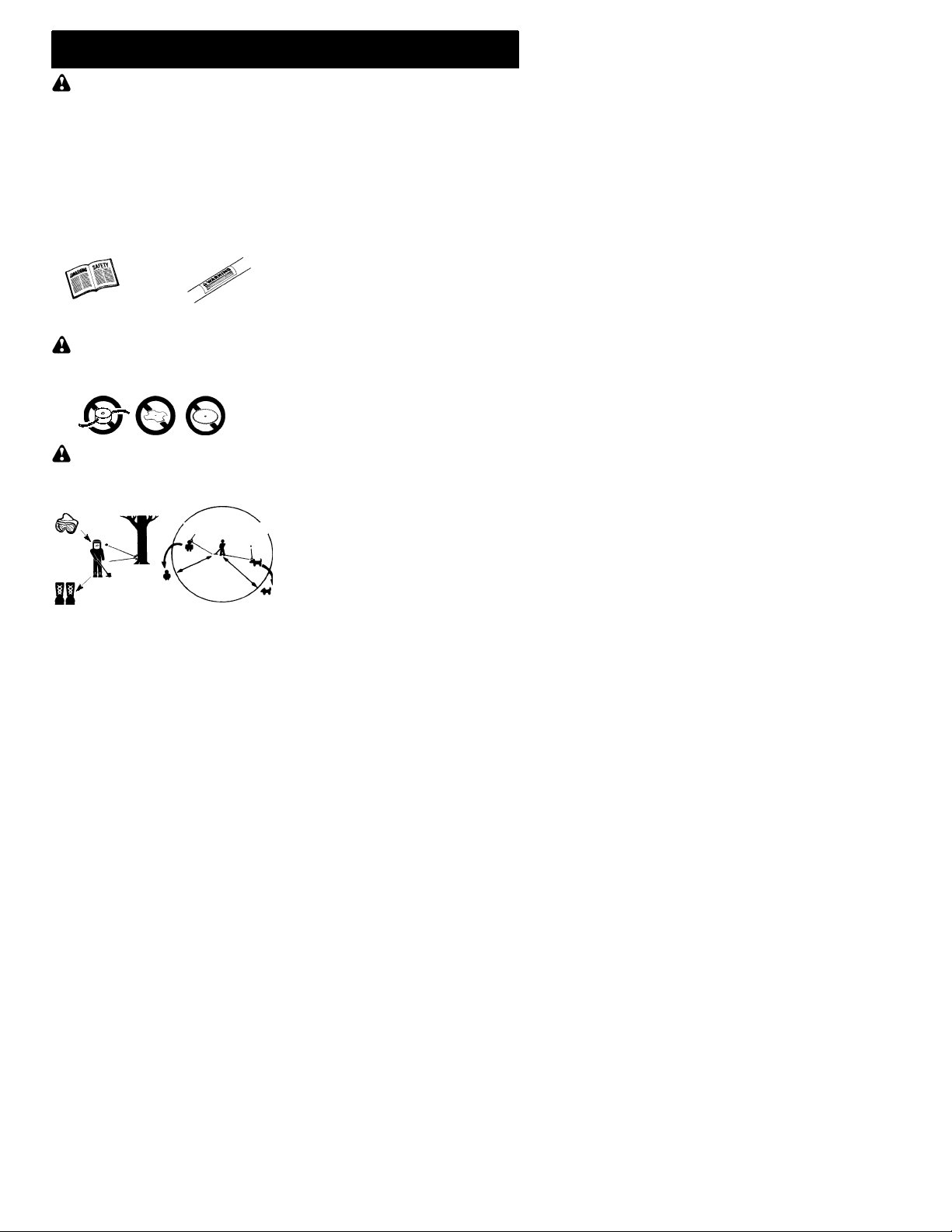
WARNING:
jects violently.Y ouand others can beblinded/injured. Wear eye and leg protection. Keep body
parts clear of rotating line.
Eye Protection
Boots
Keep children, bystanders, and animals 50 feet
(15 meters) away. If approached stop unit immediately.
If situations occur which are not covered in
this manual, use care and good judgment. If
youneedassistance,contact yourauthorized
service dealer or call 1-800-554--6723.
OPERATOR SAFETY
Dress properly. Always wear safety glasses
S
or similar eye protection when operating, or
performing maintenance, on your unit (safety
glasses are available). Eye protection should
be marked Z87.
Alwayswearfa ceordust maskif operationis
S
dusty.
Always wear heavy,longpants, long sleeves,
S
boots, and gloves. Wearing safety legguards
is recommended.
When using gardening
Operator is
SAFETY INFORMATION
ON THE UNIT
Neverusebladesorflailing
Trim mer line throw sob-
HazardZone
50 ft.
(15 m)
Always wear foot protection. Do not gobare-
S
foot or wear sandals. Stay clear of spinning
line.
Securehairabove shoulder length. Secureor
S
remov elooseclothingorclothingwithloosely
hanging ties, straps, tassels, etc. They can
be caught in moving parts.
Being fully covered also helps protect you
S
from debris and pieces of toxic plants thrown
by spinning line.
Stay Alert. Do not operate this unit when you
S
aretired,ill, upsetorundertheinfluenceofalcoho l,drugs,or medication . Watchwhat you
are doing; use common sense.
Wear hearing protection.
S
Never start or run inside a closed room or
S
build ing. Breathing exhaust fum es can kill.
Keep handles free of oil and fuel.
S
UNIT / MAINTENANCESAFETY
Disconnect the spark plug before performing
S
maintenance except carburetor adjustments.
Look for and replace damaged or loose parts
S
before each use. Look for and repair fuel
leaks before use. Keep in good working
cond ition.
Replace trimmer head partsthatare chipped,
S
cracked, broken, or d amaged in any other
way before using the unit.
Maintain unit according to recommended pro-
S
cedures. Keep cutting line at proper length.
Use only 0.080!(2 mm) diameter Weed
S
Eater"brand line. Never use wire, rope,
string, etc.
Install required shield properly be fore using
S
the unit. Use only specified trimmer head;
makesureit isproperlyinsta lledandsecurely
fastened.
Make sure unit is assembled correctly as
S
shown in this manual.
Make carburetor adjustments with lower end
S
supported to prevent line from contacting any
object.
Keep others away when making carburetor
S
adjustments.
Use only recommended Weed Eater"ac-
S
cessories and replacement parts.
Have all maintenance and service not ex-
S
plained in this manual performedby an authorized service dealer.
FUEL SAFETY
Mix and pour fuel outdoors.
S
Keep away from sparks or flames.
S
Use a container approved for fuel.
S
Do not smoke or allow smoking near fuel or
S
the unit.
Avo idspillingfuel oroil. Wipeupallfuel spills.
S
Move at least 10 feet (3 meters) away from
S
fueling site before starting engine.
Stop engine and allow to cool before remov-
S
ingfuel cap.
Always store gasoline in a container ap-
S
proved for flam mable liquids.
2
Page 3
CUTTINGSAFETY
WARNING:
each use. Remove objects (rocks, broken
glass, nails, wire, etc.) which can be thrown
by or become entangled in line. Hard objects
can damagethetrimmer headand be thrown
causing serious injury.
Use only for trimming, scalping, mowing and
S
sweeping. Do not use for edging, pruning or
hedge trimming.
Keep firm footing and balance. Do not over-
S
reach.
Keep all parts of your body away from muffler
S
and spinning line. Keep engine below waist
level.A hotmufflercancause serious burns.
Cut from your right to your left. Cutting onleft
S
side of the shield will throw debris away from
the operator.
Use only in daylight or good artificial light.
S
Use only for jobs explained in this manual.
S
TRANSPORTINGAND STORAGE
Allow engine to cool; secure unit before stor-
S
ing or transporting in vehicle.
Empty the fuel tank before storing or trans-
S
porting theunit.Useupfuel left inthecarburetorbystartingtheengine and letting it run until
it stops.
Store unit and fuel in area where fuel vapors
S
cannotreachsparks oropenflames from water heaters, electric motors or switches, furnaces, etc.
Storeunitsolinelimiter blade cannotacciden-
S
tally cause injury.The unit can behung bythe
shaft.
Store unit out of reach of children.
S
Inspect the area before
ASSEMBLY
SAFETYNOTICE:
through prolonged use of gasoline powered
handtools could cause bloodvessel ornerve
damage in the fingers, hands, and joints of
people prone to circulation disorders or abnormal swellings. Prolonged use in cold
weatherhasbeenlinkedto bloodvessel damagein otherwisehealthypeople. Ifsymptoms
occur such as numbness, pain, loss of
strength, change in skin color or texture, or
loss of feeling in the fingers, hands, or joints,
discontinuethe useof this tooland seekmedical attention. An anti--vibrationsystem does
not guarantee the avoidance of these problems. Users who operate power tools on a
continual and regular basis must monitor
closely their physical conditionandthecondition of this tool.
SPECIALNOTICE:
with a temperaturelimiting muffler and spark
arresting screen which meets the requirementsof California Codes4442 and4443. All
U.S. forest land and the states of California,
Idaho, Maine, Minnesota, New Jersey, Oregon, and Washington require by law that
many internal combustion engines be
equippedwithasparkarresting screen. Ifyou
operateinalocalewheresuchregulations exist, youarelegallyresponsibleformaintaining
theoperatingconditionof theseparts. Failure
to do so is a violation of the law. For normal
homeowneruse,themufflerandsparkarresting screen will not require any service. After
50 hours of use, we recommend that your
mufflerbeservicedorreplacedby yourauthorized service dealer.
Exposure tovibrations
This unit is equipped
WARNING:
repeatall stepstoensure yourunit is properly
assembled and all fasteners are secure.
Examine parts fordamage. Do not use damaged parts.
If you need assistance or find parts
NOTE:
missing or damaged, call 1-800-554-6723.
It is normal for the fuel filter to rattle in the
empty fuel tank.
Findingfuelor oil residueon muffler is normal
due to carburetor adjustments and testing
done by the manufacturer.
If received assembled,
ADJUSTINGTHE HANDLE
WARNING:
handle,be sureit remains above the safety label
and below the mark or arrow on the shaft.
1. Loosen wing nut on handle.
2. Rotate thehandleonthe shaft to an upright
position; retighten wing nut.
Whenadjust ing theassist
ATTACHING SHIELD
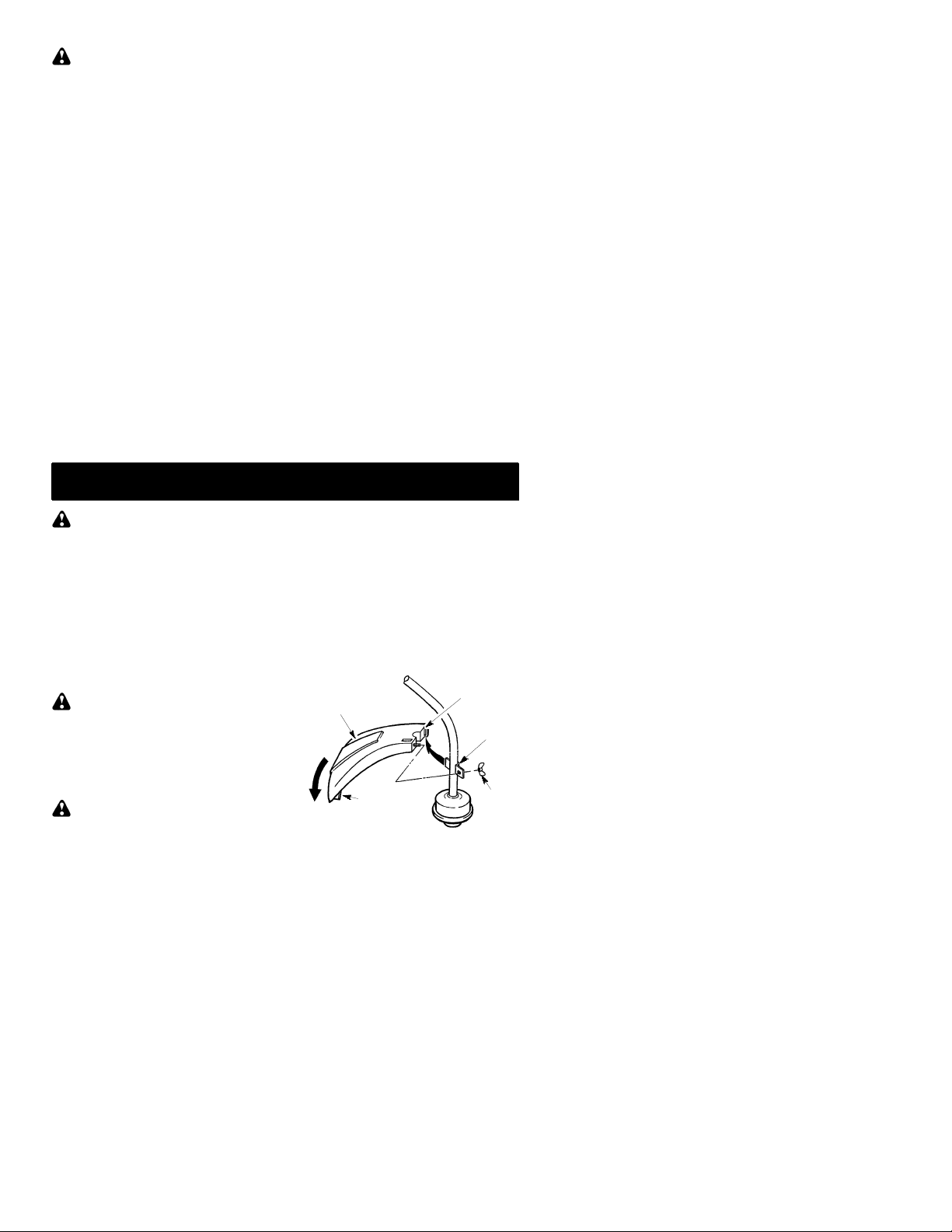
WARNING:
erly installed. The shield provides partial protection from the risk of thrown objects to theopera-
The shield must be prop-
tor andothers andis equipped with a line limiter
blade which cuts excess line to the proper
length. The line limiter blade (on underside of
shield) is sharp and can cut you.
For proper orientation of shield, see KNOW
YOUR TRIMME R illustratio n in OPERATION
section.
1. Remove wing nut from shield.
2. In sert bracket into slot as shown.
3. Pivot shielduntil bolt passes through holein
bracket.
4. Securely tighten wing nut onto bolt.
Shield
PIVOT
Line Limiter
Blade
Slot
Bracket
Wing
Nut
3
Page 4
OPERATION
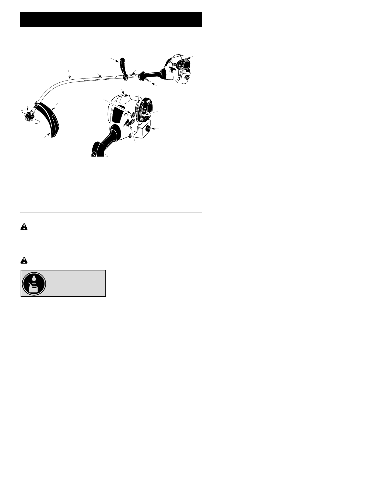
KNOW YOUR TRIMMER
READTHIS INSTRUCTIONMANUAL ANDSAFETYRULES BEFOREOPERATINGYOURUNIT.
Comp are the illustrationswith yourunit tofamiliarizeyourselfwith thelocationof thevariouscon trols
and adjustments. Save this manual for future reference.
Muffler
Shaft
Assist Handle
Safety Label
Shaft Mark
or Arrow
Spark Plug
Trimmer
Head
Line Limiter
Blade
STOP SWITCH
The STOP switch is usedto stopthe engine. To
stop the engine, push andhold theswitch in the
STOP position until the engine stops.
PRIMERBULB
ThePRIMER BULBremoves airfromthecarburetorand fuel lines and fills them with fuel.
This allows you tostart the engine with fewer
pulls on the starter rope. Activate the primer
bulb by pressing it and allowing it to return to
its original form.
Shield
STOP
Switch
BEFORE STARTINGENGINE
WARNING:
information in the safety rules before you
begin. If you do not understand the safety
rules, do not attempt to fuel your unit. Call
1-800-554-6723.
Besureto read thefuel
FUELING ENGINE
WARNING:
when refueling.
Removefuel cap slowly
HELPFUL TIP
Toobtainthe correct oilmix
ratio, pour 3.2 ounces of
2--cycle synthetic oil into
This engine is certified to operate on unleaded
gasoline. Before operation, gasoline must be
mixed with a go od quality synthetic 2-cycle
air-cooled engine oil designed to be mixed at a
ratio of 40:1. Poulan/Weed Eater brand
synthetic oil is recommended.Mix gasoline and
oilat ara tioof 40:1. A40:1 ratiois obtainedby
one gallon of fresh gas.
Primer
Bulb
Starter Handle
Throttle
Trigger
Choke Lever
Fuel Mix Fill Cap
CHOKE
The CHOKE helps to supply fuel to the engine
to aid in cold starting. Activate the choke by
moving the choke lever to the FULL CHOKE
position.Aftertheengineattempts tostart,move
the choke lever to the HALF CHOKE position.
Once engine has started, move the chokelever
to the RUN position.
mixing 3.2 ounces (95ml)ofoil with1gallon(4
liter s ) of unleaded gasoline. DO NOT USE
aut omotive oil or m arine oil. The se oils will
cause enginedamage.Whenmixing fuel, follow
instructions printed on container. Once oil is
addedto gasoline, shake containermomentarily
to a ssure that the fuel is thoroughly mixed.
Alwaysread andfollow thesafetyrules rela ting
to fuel before fueling your unit.
IMPORTANT
Experience indicates that alcohol blended
fuels (called gasohol or using ethanol or
methanol)can attractmoisturewhichleads to
separationandformationofacids duringstorage. Acidic gas can damage the fuel system
ofan enginewhile in storage. Toavoidengine
problems,emptythefuel system beforestoragefor 30 days or longer.Drainthegas tank,
startthe engineand letit rununtilthefuellines
andcarburetorare empty.Use freshfuel next
season. Never use engine or carburetorcleaner products in the fuel tank or permanent damagemayoccur. SeetheSTORAGE sectionfor
additional information.
4
Page 5

HELPFUL TIP
If your engine switch reads
“push to stop”, it is always
in the ON position.
HOW TO STOP YOUR UNIT
To stoptheengine,pushandholdtheSTOP
S
switch intheSTOPpositionuntilthe engine
stops.
If engine does notstop, move choke to the
S
FULL CHOKE position.
HOW TO STARTYOUR UNIT
WARNING:
turnwhilestartingthe engine. Avoid anycontact with the muffler.A hot muffler can cause
serious burns.
The trimmer head will
HELPFUL TIP
If your engine still does not
start after following these
instructions, please call
1--800--554--6723.
STARTINGA COLD ENGINE (or a
warm engine after running out of
fuel)
Starting Position
1. Setunitonaflatsurface.
2. Slowly press the primer bulb 6 times.
3. Move choke lever to the FULL CHOKE
position.
4. Squeeze the throttle trigger fully and hold
through
all remaining steps.
Primer Bulb
Choke
Lever
5. Pull starter rope handle sharply until engine
sounds as if it is trying to start, but do not
pullropemorethan6times.
6. As soonasenginesoundsas if it is trying to
start, move choke lever to HALF CHOKE
posit ion.
7. Pull starter rope sharply until engine runs,
but no more than 6 pulls.
If theengine doesn’t start after6
NOTE:
pulls (at the HALF CHOKE position),
move the choke lever to the FULL
CHOKE position and press the primer
bulb 6 times. Squeeze and hold the
throttle trigger and pull the starter rope2
more times. Move thechokelever to the
HALF CHOKEpositionandpull thestarterropeuntil the engineruns,but nomore
than 6 pulls. If the engine still doesn’t
start, it is probably flooded. Proceed to
STARTING A FLOODED ENGINE.
8. Oncetheenginestarts,allowittorun 10second s, then move the choke lever to the
RUN position. Allow the unit to run for 30
moresecond sat RUN beforereleasingthe
throttle trigger .
If engine dies with the choke le-
NOTE:
ver in the RUN position, move thechoke
lever to the HALF CHOKE position and
pull the rope until engine runs, but no
more than 6 pulls.
STARTINGA WARMENGINE
1. Move thechokelever tothe HALF CHOKE
posit ion.
2. Squeeze and hold the throttle trigger.Keep
throttle trigger fully squeezed until the engine runs smoothly.
3. Pull starter rope sharply until engine runs,
but no more than 6 pulls.
4. Allow engine to run 15 seconds, then move
the choke lever to RUN.
If engine has not started, pull starter
NOTE:
rope5morepulls. Ifenginestill doesnot run,it
is probably flooded.
ST ARTING A FLOODED ENGINE
Flooded engines can be started by placing the
choke lever in the RUN position; then, pull the
rope to clear the engine of excess fuel. This
could require pulling the starter handle many
times depending on how badly the unit is
flooded. If the unit still doesn’t start, refer to
TROUBLESHOOTING TABLE or call
1-800-554-6723.
Starter Handle
5
Page 6

OPERATING INSTRUCTIONS
It is recommended that the engine not be
operated for longer than 1 minute at full
throttle.
OPERA TINGPOSITION
ALWAYS WEAR:
Long pants
Heavy shoes
Cut from your right to your left.
Eye protection
WARNING:
diameter line. Other sizes of line will not advanceproperlyandwill resultin impropercuttinghead functionorcancauseseriousinjury.
Do not use other materials such as wire,
string, rope, etc. Wire can break off during
cutting and become adangerous missile that
can cause serious injury.
Use only 0.080!(2mm)
CUTTINGMETHODS
WARNING:
anddonotcrowdthe linewhen cuttingaround
hardobjects (rock, gravel, fence posts, etc.),
whichcan damagethetrimmerhead,become
entangled in the line, or be thrown causing a
serious hazard.
The tip of the line does the cutting. You will
S
achieve the best performance and minimum line wearbynot crowding the line into
the cutting area. Theright andwrongways
are shown below.
Tip of the Line
Does The Cutting
Use minimum speed
Line Crowded Into
Work Area
WARNING:
tion. Never lean over the trimmer head.
Rocks ordebris canricochet orbe throwninto
eyes and face and cause blindness or other
serious injury.
Do not run the engine at a higher speed than
necessary. The cutting line will cut efficien tly
when the engine is run at less than full throttle.
At lower speeds, there is less engine noise and
vibration.Th ecuttinglinewill lastlongerandwill
be less likely to “weld” onto the spool.
Always release the throttle trigger and allow the
engine to return to idle speed when not cutting.
To stop engine:
Release the throttletrigger.
S
Push and hold the STOP switch in the
S
STOP position until the engine stops.
TRIMMERLINEADVANCE
Thetrimmerlinewill advanceapproximately2
inches (5 cm) each time the bottom of the
trimmer headis tappedonthe groundwith the
engine running at full throttle.
The most eff icient line length is the maximum
length allowed by the line limiter.Always keep
the shield in place when the tool is being operated.
To advance line:
Operate the engine at full throttle.
S
Holdthetrimmer headparallel toandabove
S
the grassy area.
Tap the bottom of the trimmer head lightly
S
on the ground one time. Approximately 2
inches (5 cm) of line will be advancedwith
each tap.
Always tap the trimmer head on a grassy
area. Tappingon surfaces such as concrete
or asphalt can cause excessive wear to the
trimmer head.
If the line is worn down to 2 inches (5 cm) or
less,morethanonetapwill berequired toobtain the most efficient line length.
Alwaysweareyeprotec-
Right Wrong
The line will easily remove grass and
S
weedsfromaroundwalls, fences,trees and
flower beds, but it also can cut the tender
bark oftrees orshrubs andscar fences. To
help avoid damage especially to delicate
vegetation or trees with tender bark,
shorten line to 4--5 inches (10--13cm) and
use at less than full throttle.
For trimming or scalping, use less than full
S
throttle to increase line life and decrease
head wear,especially:
During light duty cutting.
S
Near objects around which the line can
S
wrap such as small posts, trees or fence
wire.
Formowingor sweeping,use full throttlefor
S
a good clean job.
TRIMMING
headabout 3inches(8cm) above theground
andat anangle.Allowonlythe tipof thelineto
make contact. Do not force trimmer line into
work area.
Trimming
3 inches (8 cm)
above ground
SCALPING
moves unwanted vegetationdown to the
ground. Hold the bottom of the trimmer head
about 3 inches (8 cm) above the ground and
atanangle.Allowthetipofthe lineto strikethe
groundaround trees,posts,monuments,etc.
This technique increases line wear.
-- Hold the bottom of the trimmer
-- The scalping technique re-
6
Page 7

Scalping
MOWING
in places conventional lawn mowers cannot
reach. In the mowing position, keep the line
parallel to the ground. Avoid pressing the
head into the ground as this can scalp the
ground and damage the tool.
Mowing
-- Y ourtrimmer is ideal for mowing
MAINTENANCE
WARNING:
plug before performing maintenance except
for carburetor adjustments.
If any dealer other than an authorized
service dealer performs work on the
product, Electrolux Home Products,
Inc., may not pay forrepairs underwar-
ranty. Itis yourresponsibility tomaintain
and perform general maintenance.
CHECK FOR LOOSE
FASTENERSAND PARTS
Spark Plug Boot
S
Air Filter
S
Housing Screws
S
Assist Handle Screws
S
Debris Shield
S
CHECK FOR DAMAGED OR
WORN PARTS
Contact an authorized service dealer for replacement of damaged or worn parts.
STOPSwitch -- Ensure STOPswitch func-
S
tions properly by pushing and holding the
switch in theSTOP position.Makesureen-
gine stops. Restart engine and continue.
Fuel Tank -- Discontinue use of unit if fuel
S
tank shows signs of damage or leaks.
Debris Shield -- Discontinue use of unit if
S
debris shield is damaged.
INSPECTAND CLEAN UNIT AND
LABELS
After each u se, inspect complete un it for
S
loose or damaged parts. Clean the unit and
labels using a damp cloth with a mild deter-
gent.
Wipe off unit with a clean dry cloth.
S
Disconnect the spark
HELPFUL TIP
IMPORTANT:
repairs other than the recommended maintenance
described in the instruction
manual performed by an
authorized service dealer.
Have all
SWEEPING
ing line can be used for a quick and easy
clean up. Keep the line parallel to and above
the surfaces being swept and move the tool
from side to side.
Sweeping
CLEAN AIR FILTER
A dirty air filter decreases engine performance and increases fuel consumption and
harmful emissions. Always clean after every
5 hours of operation.
1. Clean the air filter cover and the area
2. Open air filter cover by pushing button
NOTE:
producingharmfulevaporativeemissions, do
not clean filter in gasoline or otherflammable
solvent.
3. Washthe filter in soap and water.
4. Allow filter to dry.
5. Replace air filter and close cover.
-- Thefanningaction oftherotat-
around it to keep dirt from falling into the
carburetor chamber when the cover is
opened.
(see illustration). Remove air filter.
To avoid creating a fire hazard or
Button
Air Filter
Air Filter Cover
MUFFLER AND SPARKARRESTING SCREEN
WARNING:
uct contains chemicals known to the State of
California to cause cancer.
As yourunitisused,carbon depositsbuildup
on the muffler and spark arresting screen.
For normal homeowner use, however, the
mufflerandspark arrestingscreenwill not require any service. After 50 hours of use, we
recommend that your muffler be serviced or
replaced by your authorized service dealer.
The muffler on this prod-
7
Page 8

REPLACE SPARK PLUG
Replace the spark plug each year to ensure
the engine starts easier and runs better. Set
spark plug gap at 0.025 inch (0.6 mm). Ignition timing is fixed and nonadjustable.
SERVICE AND ADJUSTMENTS
LINE REPLACEMENT
1. Remove spool by firmly pulling on tap
button.
2. Clean entire surface of hub and spool.
3. Replace with a pre-wound spool, or cut two
leng ths of
ameter Weed Eaterrbrand line.
WARNING:
string,etc.,which canbreak offandbecomea
dangerous missile.
4. Insertends of the lines about 1/2 inch (1
cm) into the small holes on the inside of
spool.
Spool
Line exit holes
feet of 0.080!(2 mm) di-
12-1/2
Never use wire, rope,
Line in Notch
Small
Holes
1. Twist, then pull off spark plug boot.
2. Remove spark plug from cylinder and discard.
3. Replace with Champion RCJ-6Y spark
plug and tighten securely with a 3/4 inch
(19 mm) socket wrench.
4. Reinstall the spark plug boot.
CARBURETOR ADJUSTMENT
WARNING:
making idle speedadjustments. Thetrimmer
head will be spinning during this procedure.
Wearyourprotectiveequipmentandobserve
all safety precautions.
The carburetor has been carefully set at the
factory.Adjustments maybenecessaryifyou
notice any of the following conditions:
Engine will not idle when the throttle is re-
S
leased.
Make adjustments with the unit supported so
the cutting attachment is off the ground and
will not make contact with any object. Hold
theunit byhand whilerunningandmaking adjustments. Keepall parts of your body away
from the cutting attachment and muffler.
Idle Speed Adjustment
Allow enginetoidle.Adjustspeed untilengine
runs without stalling (idle speed too slow).
Turn idle speed screw clockwise to in-
S
creaseenginespeedifenginestalls ordies.
Turnidle speedscrew counterclockwise to
S
decrease engine speed.
Keepothersaway when
Idle Speed Screw
Hub
5. Wind the line evenly and tightly onto the
spool. Wind in the direction of the arrows
found on the spool.
6. Pushthe lines into thenotches, leaving 3
to 5 inches (7 -- 12 cm) unwound.
7. Insert the lines into the the exit holes in
the hubas shownin the illustration.
8. Align thenotches with the line exit holes.
9. Push spool into hub until it snaps into
place.
10. Pullthe lines extendingoutside ofthehub
to release the lines from the notches.
Line in Notch
Air Filter Cover
Ifyou requirefurtherassistance orareunsure
about performing this procedure, contact an
authorized service dealer or call
1--800--554--6723.
8
Page 9

STORAGE
WARNING:
steps after each use:
Allow engine to cool, and secure the unit
S
before storing or transporting.
Store unit and fuel in a well ventilated area
S
where fuel vapors cannot reach sparks or
open flames from water heaters, electric
motors or switches, furnaces, etc.
Store unit with all guards in place. Position
S
unit so that any sharp object cannot accidentally cause injury.
Store unit and fuel well out of the
S
children.
SEASONALSTORAGE
Prepareunit for storage atend of season orif
it will notbeusedfor 30 days or more.
If your unitis to be storedfor a period of time:
Clean the entire unit before lengthy storage.
S
Store in a clean dry area.
S
Lightly oil external metal surfaces.
S
FUEL SYSTEM
Under FUELING ENGINE in the OPERATIONsectionof thismanual,seemessagelabeled IMPORTANTregarding the use of gasohol in your engine.
Fuel stabilizer is an acceptable alternativein
minimizing the formation of fuelgum deposits
during storage. Add stabilizer to the gasoline
in the fuel tank or fuel storage container.Follow the mix instructions found on stabilizer
container.Run engineat least 5 minutesafter
adding stabilizer.
Perform the following
reach of
HELPFUL TIP
During storageof yourgas/
oilmixture,theoil will separate from the gas.
We recommend that you
shake the gas can weekly
toinsureproper blendingof
the gas and oil.
ENGINE
Remove spark plugand pour1 teaspoonof
S
40:1,2-cycle engine oil (aircooled)through
the spark plug opening. Slowly pull the
starter rope 8 to 10 times to distribute oil.
Replacesparkplugwith new oneof recom-
S
mended type and heat range.
Clean air filter.
S
Check entire unit for loose screws, nuts,
S
and bolts. Replace any damaged, broken,
or worn parts.
At the beginning of the next season, use
S
only freshfuel havingthepropergasolineto
oil ratio.
OTHER
Do not store gasoline from one season to
S
another.
Replaceyourgasoline canifit startstorust.
S
9
Page 10

TROUBLESHOOTINGTABLE
WARNING:
recommended remedies below except remedies that require operation of the unit.
Alwaysstopunitanddisconnectsparkplugbeforeperformingall ofthe
TROUBLE CAUSE REMEDY
Enginewill not
start.
Enginewill
not idle
properly.
Enginewill not
accelerate,
lacks power,
or dies under
a load.
Engine
smokes
excessively.
Engine runs
hot.
1. Engine flooded.
2. Fuel tank empty.
3. Spark plug not firing.
4. Fuel not reaching
carburetor.
5. Carburetor requires
adjustment.
1. Carburetor requires
adjustment.
2. Crankshaft seals worn.
3. Compressionlow.
1. Air filter dirty.
2. Spark plug fouled.
3. Carburetor requires
adjustment.
4. Carbon build-up on
muffler outlet screen.
5. Compressionlow.
1. Choke partially on.
2. Fuel mixture incorrect.
3. Air filter dirty.
4. Carburetor requires
adjustment.
1. Fuel mixture incorrect.
2. Spark plug incorrect.
3. Carburetor requires
adjustment.
4. Carbon build-up on
muffler outlet screen.
1. See “Starting a Flooded Engine in
Operation Section.
2. Fill tank with correct fuel mixture.
3. Install new spark plug.
4. Check for dirty fuel filter; replace.
Check for kinked or split fuel line;
repair or replace.
5. Contact an authorized service dealer.
1. See “Carburetor Adjustment” in
Service and Adjustments Section.
2. Contact an authorized service dealer.
3. Contact an authorized service dealer.
1. Clean or replace air filter.
2. Clean or replace plug
and regap.
3. Contact an authorized service dealer.
4. Contact an authorized service dealer.
5. Contact an authorized service dealer.
1. Adjust choke.
2. Empty fuel tank and refill with
correct fuel mixture.
3. Clean or replace air filter.
4. Contact an authorized service dealer.
1. See “Fueling Engine” in Operation
section.
2. Replace with correct spark plug.
3. Contact an authorized service dealer
.
4. Contact an authorized service dealer.
10
Page 11

LIMITED WARRANTY
ELECTROLUX HOME PRODUCTS, INC.,
warrantsto the original purchaser thateach new
WeedEater
is free from defects in material and
workmanship and agrees to repair or replace
under this warranty any defective gasoline
product or attachment as follows from the
original date of purchase.
2 YEARS
household purposes.
60 DAYS
commercial, professional, or income producing
purposes.
30 DAYS
purposes.
This warranty is not transferable and does not
cover damage or liability caused by impro per
handling, improper maintenance, or the use of
accessories and/orattachments notspecifically
recommended by
PRODUCTS, INC.,
this warranty does not cover tune--ups, spark
plug s, filters, starte r ropes, starter sprin gs,
cutting line, or rotating head parts that will wear
and require replacement with reasonable use
during the warranty period. This warranty does
not cover predelivery setup or normal
adjustments expla inedin theinstructionmanual.
brandgasoline tool orattachment
r
-- Parts and Labor, when used for
-- Parts and Labor, when used for
-- Parts and Labor, if used for rental
ELECTROLUX HOME
for this tool. Additionally,
THIS WARRANTY GIVES YOU SPECIFIC
LEGAL RIGHTS, AND YOU MAY HAVE
OTHER RIGHTS WHICH VARY FROM
STATE TO STATE.
NO CLAIMS FOR CONSEQUENTIAL OR
OTHER DAMAGES WILL BE ALLOWED,
AND THERE ARE NO OTHER EXPRESS
WARRANTIES EXCEPT THOSE
EXPRESSLYSTIPULATED HEREIN.
SOME STA TES DO NOT ALLOW
LIMITATIONS ON HOW LONG ANIMPLIED
WARRANTY LASTS OR THE EXCLUSION
OR LIMITATIONS OF INCIDENTAL OR
CONSEQUENTIAL DAMAGES, SO THE
ABOVE LIMITATIONS OR EXCLUSION
MAY NOT APPLYTOYOU.
The policy of
PRODUCTS, INC.,
improve its products. Therefore,
ELECTROLUX HOME PRODUCTS, INC.,
reserves the right to change, modify, or
discontinue models, designs, specifications,
and accessories of all products at any time
without notice or obligation to any purchaser.
U.S. EPA/CALIFORNIA/ENVIRONMENT CANADA
EMISSION CONTROL WARRANTY STATEMENT
YOUR WARRANTY RIGHTS AND OBLIGA-
The U.S. Environmental Protection
TIONS:
Agency, California Air Resources Board, Environment Canada and ELECTROLUX HOME
PRODUCTS, INC., are pleased to explain the
emissionscontro lsystemwarrantyonyouryear
2002--2004 small off--road engine. In California,
all small off--road engines must be designed,
built, and equipped to meet the State’s stringent
anti- -smog standards. ELECTROLUX HOME
PRODUCTS, INC., must warrant the emission
control system on yoursmall off--roadenginefor
the periods of time listed below provided there
has been no abuse, neglect, or improper maintenance of your small off--road engine. Your
emissioncontrol system includes parts such as
the carburetor and the ignition system. Wherea
warrantable condition exists, ELECTROLUX
HOMEPRODUCTS,INC., will repairyoursmall
off--road engine engine at no cost to you. Expenses coveredunderwarranty includediagnosis, parts and labor.
WARRANTY COVERAGE:
related part on your eng ine (as listed under
EmissionsControl Warranty PartsList)isdefective or a defect in the materials or workmanship
ofthe enginecauses thefailure ofsuchan emission related part, the part will be repaired or replaced by ELECTROLUX HOME PRODUCTS, INC.
RESPONSIBILITIES:
gine engine owner, you are responsible for the
performance of the required maintenance listed
MANUFACTU RER’S
If any emissions
OWNER’S WARRANTY
As thesmall off--roaden-
in your instruction manual. ELECTROLUX
HOME PRODUCTS, INC., recommends that
you retain all receipts covering maintenance on
your small off- -road engine, but ELECTROLUX
HOME PRODUCTS, INC., cannot deny warranty solely for the lack of receipts or for your
failure to ensure the performance of all scheduled maintenance. As the small off--road engine engine owner, you should be aware that
ELECTROLUX HOME PRODUCTS, INC.,
may deny you warranty coverage if your small
off--road engine engine or a part of it has failed
due to abuse, neglect, improper maintenance,
unapproved modifications, or the use of parts
not made or approved by the original equipment
manufacturer. Youareresponsible for presentingyoursmalloff--roadengineto anELEC TROLUX HOME PRODUCTS, INC., autho rizedrepair center as soon as a problem exists.
Warrant yrepa irs shouldbe completedin a reasonable amount of time, not to exceed 30 days.
If you have any questions regarding your warranty rightsandresponsibilities,you sho uld contact your nearest authorized service center or
call ELECTROLUXHOME PRODUCTS, INC.,
at 1--800--554--6723.
MENCEMENTDATE:
gins on the date the small off--road engine is
purchased.
warranty shall be for a period of two years from
the initial date of purchase.
ERED: REP AIR OR REPLACEMENT OF
PART S.
LENGTH OF COVERAGE:
Repair or replacement of any war-
11
ELECTROLUX HOME
is to continuously
WARRANTY COM-
The warranty period be-
This
WHAT IS COV-
Page 12

rantedpart will beperformedat no charge to the
owner at an approved ELECTROLUX HOME
PRODUCTS,INC.,servicingcenter.Ifyou
have any questions regarding your warranty
righ ts and responsibilities, you should contact
your nearest authorized service center or call
ELECTROLUX HOME PRODUCTS, INC., at
1--800--554--6723.
warranted part which is not scheduled for replacement as requiredmaintenance,or whichis
scheduled only for regular inspection to the effect of “repair or replace as necessary” shall be
warrantedfor 2years. Anywarranted part which
is scheduled for replacement as required maintenanceshall be warrantedfor theperiodof time
up to the first scheduled replacement point for
that part.
charged for diagnostic labor which leads to the
determination that a warranted part is defective
if the diagnostic work is performed at an approved ELECTROLUX HOME PRODUCTS,
INC., servicing center .
DAMAGES:
UCTS, INC., may beliable for damagesto other
engine components caused by the failure of a
warranted part still under warranty.
NOT COVERED
neglect, or improper maintenance are not covered.
ADD--ON OR MODIFIED PARTS:
The information on the product label indicates to which standard your engine is certified.
Example: (Year) EPA Phase I or Phase II and/or CALIFORNIA.
WARRANTYPERIOD:
DIAGNOSIS:
The owner shall not be
ELECTROLUX HOME PROD-
CONSEQUENTIAL
: All failures caused by abuse,
WHAT IS
use of add--on or modified parts can be grounds
for disallowin g a warra nty c laim. ELECTROLUX HOME PRODUCTS, INC., is not liable to
cover failures of warranted parts caused by the
use of add--on or modified parts.
ACLAIM:
your warranty rights and respo nsibilities, you
Any
should contact your nearest authorized service
center or call ELECTROLUX HOME PRODUCTS, INC., at 1--800--554--6723.
GET WARRANTY SERVICE:
vices or repairs shall be provided at all ELECTROLUX HOME PRODUCTS, INC., service
centers. Call: 1--800- -554--6723.
NANCE, REPLACEMENT AND REPAI R OF
EMISSION RELATED PARTS
TROLUXHOME PRODUCTS, INC.,approved
replacement part used in the performance of
any warranty maintenance or repair on emission related parts will be provided without
charge tothe owner if thepart is underwarranty.
EMISSION CONTROL WARRANTY P ARTS
LIST :
(covered up to maintenance schedule), Ignition
Module, Muffler including catalyst.
NANCE STATEMENT:
ble for the performance of all required maintenance as defined in the instruction manual.
The
If you have any questions regarding
Carburetor, Ignition System: Spark Plug
Theowneris resp onsi-
HOW TOFILE
WHERETO
Warranty ser-
: Any ELEC-
MAINTE-
MAINTE-
This engine is certified to be emissions compliant for the following use:
Moderate (50 hours)
Intermediate (125 hours)
Extended (300 hours)
12
 Loading...