

Page 1

Trademark
R
Instruction Manual
Manual de Instrucciones
Manuel d’Instructions
BV200 / BV1650 / BV1800
BV1850 / BV2000
LE Series
IMPORTANT MANUAL -- Do not throw away
MANUAL IMPORTANTE -- No lo descarte
MANUEL IMPORTANT -- À Conserver
ENGLISH
ESPAÑOL
WARNING:
Read and follow all Safety Rules and Operating Instructions before
using this product. Failure to do so can result in serious injury.
ADVERTENCIA:
Lea el manual de instrucciones y siga todas las advertencias e
instrucciones de seguridad. El no hacerlo puede resultar en lesiones
graves.
AVERTISSEMENT:
Veuillez lire le manuel d’instructions et bien respecter tous les
avertissements et toutes les instructions de sécurité. Tout défaut
de le faire pourrait entraîner des blessures graves.
Electrolux Home Products, Inc.
104 Warren Road
Augusta, GA 30907
CopyrightE2004 ElectroluxHome Products, Inc.
530163806
2/4/04
FRANÇAIS
Page 2

SAFETY RULES
WARNING:
Safety Rules and Precautions can result in
serious injury.
KNOW YOURUNIT
Readyour instructionmanualcarefullyuntil
S
you completely understand and canfollow
all warnings andsafety rulesbeforeoperating the unit.
Restrict unit to users who understand and
D
will follow all warnings and safety rules in
this manual.
WARNING:
ing unit. Remove all debris and hard objects
such as rocks, gla ss , wire, etc. that can ricochet, be thrown, or otherwise cause injury or
damage during operation.
Use your unit as a blower for:
Sweeping debris or grass clippings from
D
drivew ays, sidewalks, patio s,etc.
Blowing grass clippings, straw,or leaves into
D
piles, around joints, or betwee nbricks.
Use your unit as a vacuum for:
Picking up dry material such as leaves,
D
grass, small twigs, and bits of paper.
For best results during vacuum use, operate
D
your unit at high speed.
Moveslowly back and forthover the mate-
D
rial as you vacuum. Avoid forcing the unit
intoapileofdebrisas this canclog theunit.
Keep the vacuum tube about an inch above
D
thegroundforbestresults.
PLAN AHEAD
Always wear eye protection when operat-
D
ing, servicing, or performing maintenance
on unit. Wearing eye protectionwill helpto
preventrocksor debris from being blownor
ricocheting into eyes and face which can
result in blindness and/or serious injury.
Eye protection should be marked Z87.
Always wear foot protection. Do not go
D
barefoot or wear sandals.
Always wear respirator orface mask when
D
working with unit in dusty environments.
Secure hair above shoulder length. Secure
D
or remove jewelry, loose clothing, or clothing with loosely hanging straps, ties, tassels, etc. They can be caught in moving
parts.
Donotoperateunit whenyouaretired,ill, up-
D
set, or if you are under the influence of alcohol, drugs, or medication.
Keep children, bystanders, and animals
D
away from work area a minimum of 30 feet
(10meters) when starting or operatingunit.
Do not point the blower nozzle in the direction of people or pets.
HANDLEFUEL WITH CAUTION,IT IS
HIGHLY FLAMMABLE
Eliminate all sources of sparksor flame(in-
D
cluding smoking,open flames, or work that
cancausesparks)intheareaswherefuelis
mixed, poured, or stored.
Failure to follow all
Inspect area before start-
Mix and pour fuel in an outdoor area; store
D
fuel in a cool, dry,well ventilated place; use
an approved, marked container for all fuel
purposes.
Do not smoke while handling fuel or while
D
operating the unit.
Make sure the unit is properly assembled
D
and in good operating condition.
Do not fill fuel tank while engine is hot or
D
running.
Avoidspilling fuel or oil. Wipe up fuel spills
D
before starting engine.
Moveatleast 10 feet (3 meters)awayfrom
D
fuel and fueling site before starting engine.
Always store gasoline in a container ap-
D
proved for flammable liquids.
OPERATE YOUR UNIT SAFELY
WARNING:
opening the vacuum inlet door. The engine
must be stopped and the impeller blades no
longerturningtoavoid serious injury fromthe
rotating blades.
Inspect unit before each use for worn,
D
loose, missing, or damaged parts. Do not
use until unit is in proper working order.
Keep outside surfaces free of oil and fuel.
D
Never start or run engine inside a closed
D
room, building or other unventilated area.
Breathing exhaust fumes can kill.
To avoid static electricity shock, do not
D
wear rubber gloves or any other insulated
gloves while operating unit.
Do not set unit on any surface except a
D
clean, hard area while engine is running.
Debris such as gravel, sand, dust, grass,
etc.couldbe picked up by theair intakeand
thrown out through discharge opening,
damagingunit, property,or causing serious
injury to bystanders or operator.
Avoiddangerousenvironments.Donotuse
D
in unventilated areas or where explosive
vapors or carbon monoxide build up could
be present.
Do notoverreach or use from unstable sur-
D
faces such as ladders,trees, steep slopes,
rooftops,etc. Keepfirm footing andbalance
at all times.
Never place objects inside the blower
D
tubes; always direct the blowing debris
awayfrom people,animals,glass,andsolid
objects such as trees, automobiles, walls,
etc.Theforceofaircancauserocks, dirt,or
sticks tobethrownor toricochet which can
hurt people or animals, break glass, or
cause other damage.
Never run unit without the proper equip-
D
ment attached. When using your unit as a
blower,always install blower tubes. When
usingyour unit as avacuum, always install
vacuumtubesand vacuum bagassembly.
Makesurevacuum bagassembly is completely zipped.
Check air intake opening, blower tubes,
D
vacuum tubes, and elbow tubefrequently,
always with engine stopped and spark
Stop the engine before
-- 2 --
Page 3
plug disconnected. Keep vents and discharge tubes free of debris which can accumulate and restrict proper air flow.
Never place any object in the air intake
D
opening as this could restrict proper air flow
and cause damage to the unit.
Never use for spreading chemicals, fertil-
D
izers, or othersubstanceswhich may contain toxic materials.
To avoid spreading fire, do not use near
D
leaf or brush fires, fireplaces, barbecue
pits, ashtrays, etc.
Use only for jobs explainedin this manual.
D
MAINTAIN YOUR UNIT PROPERLY
Have all maintenance other than the rec-
D
ommendedproceduresdescribedin theinstruction manual performed by an authorized service dealer.
Disconnect spark plug before performing
D
maintenance except for carburetor adjustments.
Use only recommended Weed Eater!re-
D
placement parts; use of any other parts
may void yourwarrantyandcause damage
to your unit.
Empty fuel tank before storing the unit. Use
D
upfuel left incarburetor by startingengineand
letting it run until it stops.
Do not use any accessory or attachment
D
other than those recommended by manufacturer for use with your unit.
Donotstore the unit or fuel in a closedarea
D
where fuel vapors can reach sparks or an
openflame from hotwaterheaters,electric
motors or switches, furnaces, etc.
Store in a dry areaout of reachof children.
D
ASSEMBLY
SPECIAL NOTICE:
tions throughprolongeduse of gasoline powered hand tools could cause blood vessel or
nerve damage in the fingers, hands, and
joints of people prone to circulation disorders
or abnormal swelling. Prolonged use in cold
weatherhasbeenlinked toblood vessel damagein otherwise healthypeople.Ifsymptoms
occur such as numbness, pain, loss of
strength, change in skin color or texture, or
loss of feeling in the fingers, hands, or joints,
discontinue the use of this tool and seek
medical attention. An antivibration system
does not guarantee the avoidance of these
problems. Users who operatepower tools on
a continual and regular basis must monitor
closely their physical condition andthecondi-
Exposure to vibra-
tion of this tool.
SPECIAL NOTICE:
with a temperaturelimiting muffler and spark
arresting screen which meets the requirementsof CaliforniaCodes 4442and4443. All
U.S. forest land and the states of California,
Idaho, Maine, Minnesota, New Jersey, Oregon, and Washington require by law that
many internal combustion engines be
equippedwithasparkarrestingscreen. Ifyou
operateinalocalewheresuch regulationsexist, youarelegally responsibleformaintaining
theoperatingconditionofthese parts. Failure
to do so is a violation of the law. Refer to the
MAINTENANCE section for information on
maintenance of the muffler and spark arrest-
This unit is equipped
ing screen.
WARNING:
the impeller blades have stopped turning before opening the vacuum inlet door or attempting to insert or remove the vacuum or
blower tubes. The rotatingblades can cause
serious injury. Always disconnect the spark
plug before performing maintenance or accessing movable parts.
WARNING:
assembled, check each step to insure your
unit is properly assembled and all fasteners
are secure. Follow all safety information in
the manual and on the unit.
A standard screwdriver is requiredfor as-
D
sembly.
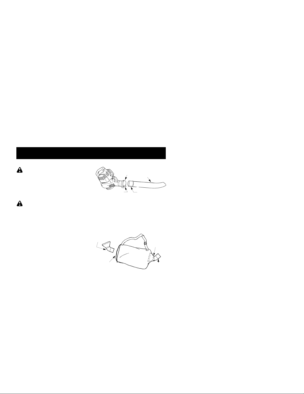
BLOWERTUBE ASSEMBLY
1. Align the rib on the blower tube with the
groove in the blower outlet; slide the tube
into place.
Knobmustbe looseenough toallow
NOTE:
blower tube to be inserted in blower outlet.
Loosen knob by turning counterclockwise.
Stop engine and be sure
If you receive your unit
Blower
Outlet
Groove
2. Securethe tubeby turningthe knob clockwise.
3. Toremovethetube, turntheknobcounterclockwise to loosen the tube; remove the
tube.
VACUUM BAG ASSEMBLY
1. Open the zipper on the vacuum bag and
insert the elbow tube.
2. Push the small end of the elbow tube
through the small opening in the bag.
Elbow
Tube
Blower
Tube
Rib
Zipper
Opening
-- 3 --
Small
Opening
Rib
Page 4
Makesureedgeof thesmallopening
NOTE:
is flush against the flared area of the elbow
tube, and the rib on the elbow tube is on the
bottom.
3. Closethe zipperon thebag.Makesurethe
zipper is closed completely.
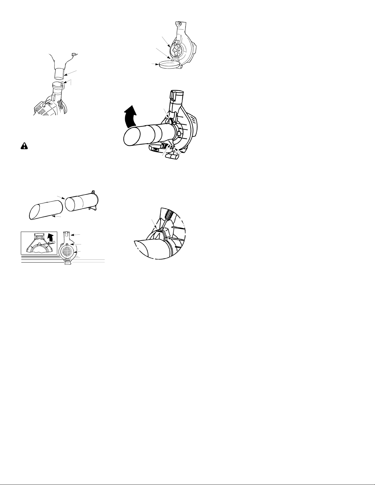
4. Remove blower tube from engine.
Rib
Groove
4. Hold the vacuum inlet cover open until upper vacuum tube is installed.
Vacuum Inlet
RetainingPost
Vacuum
Inlet
5. Place the hooksof theupper vacuum tube
6. Pivot the tube until it is secured to the
Cover
on the retaining posts of the unit.
blower unit by the vacuum inlet latch.
5. Inserttheelbowtubeinto theblower outlet.
Make sure elbow tube rib is aligned with
the blower outlet groove.
6. Turnknobclockwisetosecure elbowtube.
VACUUM TUBE ASSEMBLY
WARNING:
the impeller blades have stopped turning before opening the vacuum inlet door or attempting to insert or remove the vacuum or
blower tubes. The rotatingblades can cause
serious injury.
1. Align the lower vacuum tube as shown.
Push lower vacuum tube into uppervacuum tube.
Upper Vacuum
Tube
2. Insert thetip ofa screwdriverinto thelatch
area of the vacuum inlet.
Latch
Area
3. Gently tilt the handle ofthescrewdriver toward the back of the unit to release the
latch while pulling up on the vacuum inlet
cover with your other hand.
Stop engine and be sure
Lower Vacuum Tube
Blower
Outlet
Latch Area
Vacuum
Inlet Cover
PIVOT
Inlet Cover
Latch
Hook
Retaining
Post
HOW TO CONVERT UNIT FROM
VACUUM USE TO BLOWER USE
1. Remove the vacuum tubes by inserting
the tip of a screwdriver intothe latch area
of the vacuum inlet.
2. Gently tilt handle of screwdriver toward
the back of the unit to release the latch
whilepullingup on theupper vacuum tube
with your other hand.
Latch Area
3. Remove the vacuum bag.
4. Close the vacuum inlet cover and make
sure it is latched closed.
5. Reinstall the blower tube (see BLOWER
TUBE ASSEMBLY).
-- 4 --
Page 5

SHOULDERSTRAP ADJUSTMENT
1 Hold the unit as shown with the muffler side
facing away from your body and clothes.
2. Pass the shoulder strap over your head
and onto your right shoulder.
3. Extendyour left arm towardthe rear of the
vacuum bag.
4. Adjust shoulder strap until the vacuum
bag/shoulder strap seam lies between
your thumb and index finger.
5. Make sure air flows freely from the elbow
tubeinto bag. If bag is kinked, the unit will
not operate properly.
OPERATION
KNOW YOUR BLOWER
READTHIS INSTRUCTIONMANUALAND SAFETY RULES BEFORE OPERATINGYOURUNIT .
Comp aretheillustrations with yourunit to familiarizeyourselfwith thelocatio nof thevariou scontrols
and adjustments. Save this manual for future reference.
Lower
Vacuum Tube
Upper
Vacuum Tube
Vacuum Bag
Elbow Tube
Blower
Tube
THROTTLE LEVER
TheTHROTTLELEVER is usedto selectthe
desiredengine speedand to stop the engine.
Movethethrottlelever tothe
full speed operation. Move the throttle lever
tothe
engine, move the throttle lever to the STOP
position.
PRIMERBUTTON
The PRIMER BUTTON removes air from the
carburetorand fuellines andfills themwith fuel.
This allow s you to start the engine with fewer
pulls on the starter rope. Activate primer button
by pressing it and allowing it to return to its original position.
positionfor idle speed. Tostopthe
Spark Plug
position for
Primer Button
Throttle
Lever
CHOKE LEVER
The CHOKE helps to supply fuel to the engine
to aid in cold starting. Activate the choke by
moving the choke lever to the FULL CHOKE
position.Afterengineattemptstostart, movethe
choke lever to the HALF CHOKE position.
Once engine starts, move choke lever to the
RUN position.
Choke Lever
Fuel Mix
Fill Cap
Starter
Rope
Rear
Handle
-- 5 --
Page 6

OPERA TINGPOSITION
Eye
Protection
Blower
OPERA TINGTIPS
While vacuuming or blowing debris, hold
S
the unit with the muffler side facing away
from your body and clothes (seeOPERATING POSITION illustration above).
To reduce the risk of hearing loss
S
associated with sound level(s), hearing
protection is required.
T o reduce the risk of injury associated with
S
contacting rotating parts, stop the engine before installing or removing attachments. Do
not operate without guard(s) in place.
Operate power equipment only atreasonable
S
hours- -notearly in the morning or late at night
whenpeoplemight be disturbed.Comply with
times listed in local ordinances. Usual recommendations are 9:00 a.m. to 5:00 p.m.,
Monday though Saturday.
To reduce noise levels, limit the number of
S
pieces of equipmentused at any one time.
To reduce noise levels, operate power
S
blowers at the lowest possible throttle
speed to do the job.
Use rakes and brooms to loosen debris be-
S
fore blowing.
In dusty conditions, slightly dampen sur-
S
faces or use a mister attachmentwhen water is available.
Conserve water by using power blowers
S
instead of hoses for many lawn and garden
applications, including areas such as gutters,
screens, patios,grills, porches,andgard e ns.
Watchoutfor children, pets,openwindows,
S
or freshly washedcars. Blow debris away
safely.
Use the full blower nozzle extension so the
S
air stream can work close to the ground.
After using blowers and other equipment,
S
CLEAN UP! Dispose of debris in trash receptacles.
Vacuum
BEFORE STARTINGENGINE
WARNING:
information in the safety rules before you begin.If you do not understand the safety rules,
do not attempt to fuel your unit. Call
1-800-554-6723
Be sure to read the fuel
.
FUELING ENGINE
WARNING:
when refueling.
Remove fuel cap slowly
This engine is certified to operate on
unleaded gasoline. Before operation,
gasoline must be mixed with a good quality
synthetic 2-cycle air-cooled engine oil
designed to be mixed at a ratio of 40:1.
Poulan/Weed Eater brand synthetic oil is
recommended. Mix gasoline andoil at a ratio
of40:1. A40:1 ratio is obtainedby mixing 3.2
ounces (95 ml) of oil with 1 gallon (4 liters) of
unleaded gasoline. DO NOT USE
automotiveoil orboatoil.Theseoils willcause
engine damage. When mixing fuel, follow
instructions printed on container. Once oil is
added to gasoline, shake container
momentarily to assure that the fuel is
thoroughlymixed. Always readandfollow the
safetyrulesrelatingto fuel beforefuelingyour
unit.
IMPORTANT
Experience indicates that alcohol blended
fuels (called gasohol or using ethanol or
methanol)can attract moisture which leads to
separation and formation of acids during
storage. Acidic gas can damage the fuel
systemofanenginewhile instorage.Toavoid
engine problems, empty the fuel system
beforestoragefor 30days or longer.Drainthe
gastank,starttheengine andlet it rununtil the
fuellines andcarburetorareempty.Usefresh
fuel next season. Never use engine or
carburetorcleaner products in thefueltankor
permanent damage may occur.
Unit must be placed on its side when
NOTE:
add ing fuel (see illustrationbelow).
TO STOP THE ENGINE
To stop the engine, move the throttle lever
D
to the STOP position.
BEFORE STARTINGTHE ENGINE
WARNING:
the tubes are secure before using the unit.
Fuel engine. Move at least 10 feet (3 me-
D
ters) away from the fueling site.
Hold the unit in the starting position as
D
shown. Make sure the blower end is directed away from people, animals, glass,
and solid objects.
YouMUSTmakesure
-- 6 --
Page 7

STARTING POSITION
Blower
Vacuum
WARNING:
holdtheunitasillustrated.Donotsetunitonany
surface except aclean, hard area when starting
engine or while engine is running. Debris such
as gravel, sand, dust, grass, etc. could be
picked up by the air intake and thrown out
through the discharge opening, damaging the
unit or property, or causing serious injury to bystanders or the operator.
When starting engine,
STARTING A COLD ENGINE
1. Move throttle lever to the position.
2. Move choke lever to the FULL CHOKE
position.
3. Slowly press the primer button 8 times.
Throttle Lever
4. Pull starter rope sharply until engine attemptstorun, butnomorethan5pulls(below 30_F, 8 pulls).
Primer Button
Choke Lever
If engine attempts tostart beforethe
NOTE:
th
pull, go to next step immediately.
5
5. Move the choke lever to the HALF
CHOKE position.
6. Pull the starter rope sharply until the engine runs, but nomore than 5 pulls (below
30_F, 10 pulls).
7. After a 5 second warm--up, move the
choke lever to the RUN position.
8. Allow the unit to run for 30 more seconds
at the RUN position before moving the
throttle lever to the
If engine has not started after 5 pulls (at HALF
CHOKE), repeat STARTING A COLD ENGINE
procedure. If engine still does not start, proceed
to STAR TING A FLOODED ENGINE.
9. Tostop the engine, move the throttle leverto
theSTOPposit ion.
position.
STARTING A WARMENGINE
If fuel tank is empty, add fuel; then,
NOTE:
follow STARTING A COLD ENGINE procedure. Do not fill fuel tank while engine is hot.
1. Move throttle lever to the
2. Pull starter rope sharplyuntil engine runs,
but no more than 5 pulls.
If engine has not started, pull starter
:
NOTE
rope5 morepulls. If engine still does notrun,
it is probably flooded.
3. Tostop the engine, move the throttle leverto
theSTOPposit ion.
position.
ST ARTING A FLOODED ENGINE
Flooded engines can be started by placing the
choke lever in the RUN position. Move throttle
lever to the fast positio n
until engine starts. After engine starts, move the
throttle lever to the slow position
eng ine to idle.
Star ting could require pu lling the starter rope
many times depending on how badly the unit is
flooded.
If unit still doesn’t start refer to the TROUBLESHOOTING TABLE or call 1-800-554-6723.
; then, pull rope
toallow
MAINTENANCE
WARNING:
unless engine and muffler are cold. A hot
muffler can cause serious burns.
WARNING:
the impeller blades have stopped turning before opening the vacuum inlet door or attempting to insert or remove the vacuum or
blower tubes. The rotatingblades can cause
serious injury. Always disconnect the spark
plug before performing maintenance or accessing movable parts.
GENERALRECOMMENDATIONS
Thewarrantyonthisunit doesnotcover items
that have been subjected to operator abuse
or negligence. To receive full value from the
warranty, the operator must maintain unit as
Avoid touching muffler
Stop engine and be sure
instructed in this manual. Various adjustments will need to be made periodically to
properly maintain your unit.
CHECK FOR LOOSE
FASTENERSAND PARTS
Spark Plug Boot
S
Air Filter
S
Housing Screws
S
Muffler
S
CHECK FOR DAMAGED OR WORN
PARTS
Contact an authorized service dealer for replacement of damaged or worn parts.
Fuel Tank -- Do not use unit if fuel tank shows
S
signs of damage or leaks.
VacuumBag -- Do not use vacuum bag if it
S
is torn or damaged.
-- 7 --
Page 8

INSPECTAND CLEAN UNIT AND
DECALS
After each use, inspect complete unit for
S
looseordamagedparts. Clean the unitand
decals using adampcloth witha mild detergent.
Wipe off unit with a clean dry cloth.
S
CLEAN AIR FILTER
Fuel Line
Fuel Filter
Air Filter
Cover
Air Filter
Cleaning the air filter:
A dirty air filter decreases engine performance and increases fuel consumption and
harmful emissions. Always clean or replace
air filter after every 5 hours of operation or
yearly, whichever comes first.
1. Clean the cover and the area around it to
keepdebris from fallinginto thecarburetor
chamber when the cover is removed.
2. Remove parts as illustrated.
Donotclean filter in gasoline orother
NOTE:
flammable solvent. Doingsocancreateafire
hazardorproduceharmfulevaporativeemissions.
3. Wash the filter in soap and water.
4. Allow filter to dry.
5. Apply a few drops of oil to the filter;
squeeze filter to distribute oil.
6. Replace parts.
REPLACE SPARKPLUG
Replace spark plug each year to ensure the
engine starts easier and runs better. Set
sparkpluggap at 0.025inch.Ignitiontimingis
fixed, nonadjustable.
1. Twist, then pull off spark plug boot.
2. Remove spark plug from cylinder and discard.
3. Replace with Champion RCJ-6Y spark
plug and tighten securely with a 3/4 inch
socket wrench.
4. Reinstall the spark plug boot.
REPLACE FUEL FILTER
Toreplacefuel filter,drainunit byrunningit dry
of fuel, then removefuel cap/retainerassembly from tank. Pull filter from tank andremove
itfromthefuel line. Installnew fuelfilter onfuel
line; reinstall parts.
Screws
CHECK MUFFLER MOUNTING
SCREWS
Once each year, ensure muffler mounting
screws are secure and tightened properly to
prevent damage.
Muffler Cover
Screws
1. Loosenand removethe 2 screws fromthe
muffler cover.
2. Remove the muffler cover.
3. Tightenthe 2 muffler mountingscrews securely.
4. Reinstall muffler cover and 2 screws.
Tighten securely.
INSPECT MUFFLER AND SPARK
ARRESTINGSCREEN
WARNING:
uct contains chemicals known to the State of
California to cause cancer.
As the unit is used, carbon deposits build up
on the muffler and spark arresting screen,
andmust be removedto avoid creating a fire
hazard or affecting engine performance.
VIEW OF MUFFLER
Spark arresting
screen
Exhaust
Diverter
Screws
Replace the spark arrestingscreen every 50
hoursof operation orif any damage orbreaks
in the screen are noted.
The muffler on this prod-
-- 8 --
Mounting
Screw
Holes
Page 9

Donot attempttocleanthe spark ar-
NOTE:
resting screen.
1. Loosenand removethe 2 screws fromthe
muffler cover. Remove the muffler cover.
2. Loosen and remove bothscrews from the
exhaust diverter.
3. Remove the exhaust diverter and spark
arresting screen.
4 Install new spark arresting screen.
5. Reinstall exhaust diverter and both
screws. Tighten screws securely.
6. Reinstall muffler cover and 2 screws.
Tighten securely.
If any part of the muffler is cracked,
NOTE:
broken or damaged, we recommend thatthe
muffler be replaced.
STORAGE
WARNING:
steps after each use:
Allow engine to cool, and secure the unit
S
before storing or transporting.
Store unit and fuel in a well ventilated area
S
where fuel vapors cannot reach sparks or
open flames from water heaters, electric
motors or switches, furnaces, etc.
Store unit with all guards in place. Position
S
unit so that any sharp object cannot accidentally cause injury.
Store unit and fuel well out of the reach of
S
children.
SEASONALSTORAGE
Prepareunit forstorageat endofseason or if
it will not be used for 30 days or more.
If your unitis to be storedfor a period of time:
Clean the entire unit before lengthy stor-
S
age.
Store in a clean dry area.
S
Lightly oil external metal surfaces.
S
FUEL SYSTEM
Under FUELING ENGINE in the OPERATIONsectionof this manual,seemessagelabeled IMPORTANT regarding the use of gasohol in your engine.
Perform the following
CARBURETOR ADJUSTMENTS
Thereis no screw for idle adjustment on your
blower. The throttle lever is used to control
engine speed. The throttle lever can be
placed in one of four positions: STOP, IDLE
, FULL THROTTLE or , and one
or
intermittentposition. Ifyourenginewill notrun
properly or you require further assistance,
contact an authorized service dealer or call
1--800--554--6723.
Fue l stabilizer is an acce ptab le alterna tive in
minimizing the formation of fuel gum deposits
during storage. Addstabilizerto gasolinein fuel
tank or fuel storage container. Follow the mix
instruction s found on stabilizer contain e r. Run
eng ineat least 5 minutes afteraddingstabilize r.
ENGINE
Remove spark plug and pour1teaspoonof
S
40:1,2-cycle engine oil (air cooled) through
the spark plug opening. Slowly pull the
starter rope 8 to 10 times to distribute oil.
Replacespark plug with new one ofrecom-
S
mended type and heat range.
Clean air filter.
S
Check entire unit for loose screws, nuts,
S
and bolts. Replace any damaged, broken,
or worn parts.
At the beginning of the next season, use
S
only freshfuelhavingthepropergasolineto
oil ratio.
OTHER
Do not store gasoline from one season to
S
another.
Replaceyourgasolinecan if it starts torust.
S
-- 9 --
Page 10

TROUBLESHOOTINGTABLE
WARNING:
recommended remedies below other than remedies that require operation of the unit.
TROUBLE
Enginewill not
start.
Enginewill not
idle properly.
Enginewill not
accelerate,
lacks power, or
dies under a
load.
Engine smokes
excessively.
Engine runs hot.
Always stopunitanddisconnect spark plug before performingany of the
CAUSE REMEDY
1. Engine flooded.
2. Fuel tank empty.
3. Spark plug not firing.
4. Fuel not reaching
carburetor.
5. Compressionlow.
1. Fuel not reaching
carburetor.
2. Carburetor requires
adjustment.
3. Crankshaft seals worn.
4. Compressionlow.
1. Air filter dirty.
2. Fuel not reaching
carburetor.
3. Spark plug fouled.
4. Carburetor requires
adjustment.
5. Carbon build up.
6. Compressionlow.
1. Choke partially on.
2. Fuel mixture incorrect.
3. Air filter dirty.
4. Carburetor requires
adjustment.
1. Fuel mixture incorrect.
2. Spark plug incorrect.
3. Carburetor requires
adjustment.
4. Carbon build up.
1. See “Starting a Flooded Engine”
in Operation section.
2. Fill tank with correct fuel mixture.
3. Install new spark plug.
4. Check for dirty fuel filter; replace.
Check for kinked or split fuel line;
repair or replace.
5. Contact an authorized service dealer.
1. Check for dirty fuel filter; replace.
Check for kinked or split fuel line;
repair or replace.
2. Contact an authorized service dealer.
3. Contact an authorized service dealer
4. Contact an authorized service dealer.
1. Clean or replace air filter.
2. Check for dirty fuel filter; replace.
Check for kinked or split fuel line;
repair or replace.
3. Clean or replace spark plug
and re-gap.
4. Contact an authoriz ed service dealer.
5. Contact an authoriz ed service dealer.
6. Contact an authoriz ed service dealer.
1. Adjust choke.
2. Empty fuel tank and refill with
correct fuel mixture.
3. Clean or replace air filter.
4. Contact an authorized service dealer.
1. See “Fueling Engine” in Operation
section.
2. Replace with correct spark plug.
3. Contact an authorized service dealer.
4. Contact an authorized service dealer.
-- 1 0 --
Page 11

LIMITED WARRANTY
ELECTROLUX HOME PRODUCTS, INC.,
warrantsto theoriginal purchaser that eachnew
Weed Eater
is free from defects in material and workmanship and agrees to repair or replace under this
warranty any defective gasoline product or attachment as follows from the original date of
purchase
2 YEARS--
household purposes.
90 DAYS --
commercial, professional, or income producing
purposes.
30 DAYS --
purposes.
This warranty is not transferable and does not
cover dama ge or liability caused by imprope r
handling, improper maintenance, or the use of
accessories and/or attachments not specifically
recommended by
PRODUCTS, INC.,
this warranty does not cover tune-ups, spark
plugs, filters, starter ropes, starter springs, cutting line, or rotatingheadparts thatwill wearand
require replacement with reasonable useduring
the warranty period. This warranty does not
brand gasoline tool or attachment
:
Parts and Labor, when used for
Parts and Labor, when used for
Parts and Labor , if used for rental
ELECTROLUX HOME
for this tool. Additionally,
U.S. EPA/CALIFORNIA
EMISSION CONTROL WARRANTY STATEMENT
YOUR WARRANTY RIGHTS AND OBLIGA-
The U.S. Environmental Protection
TIONS:
Agency/California Air Resources Board and
ELECTROLUXHOME PRODUCTS, INC., are
pleasedtoexplaintheemissionscontrolsystem
warranty on your year 2002- -2004 small off- road engine. In California, all new small off--road
engines must be designed, built, and equipped
to meet the State’s stringent anti- -smog standards. ELECTROLUX HOME PRODUCTS,
INC.,mustwarranttheemissioncontrolsystem
on your small off- -road engine for the periods of
time listed below provided there has been no
abuse, neglect, or improper maintenance of
your small off- -road engine engine. Your emission control system includes parts such as the
carb u reto r an d the ignition system. Where a
warrantable condition exists, ELECTROLUX
HOMEPRODUCTS,INC., will repair yoursmall
off--road engine engine at no cost to you. Expenses covered under warranty includediagnosis, parts and labor.
WARRANTY COVERAGE:
related part on your engine (as listed under
EmissionsControl WarrantyParts List) is defective or a defect in the materials or workmanship
ofthe enginecauses thefailure of such an emission related part, the part will be repaired or replaced by ELECTROLUX HOME PRODUCTS, INC.
SPONSIBILITIES:
gine engine owner, you are responsible for the
performance of the required maintenance listed
in your instruction manual. ELECTROLUX
HOME PRODUCTS, INC., recommends that
you retain all receipts covering maintenanceon
MANUFACTU RER’S
If any emissions
OWNER’S WARRANTY RE-
As the small off--road en-
cover predelivery setup or normal adjustments
explained in the instruction manual.
THIS WARRANTY GIVES YOU SPECIFIC
LEGAL RIGHTS, AND YOU MA Y HAVE
OTHER RIGHTS WHICH VARY FROM
STA T E TO STA TE.
NO CLAIMS FOR CONSEQUENTIAL OR
OTHER DAMAGES WILL BE ALLOWED,
AND THERE ARE NO OTHER EXPRESS
WARRANTIES EXCEPT THOSE EXPRESSLY STIPULATED HEREIN.
SOME STATES DO NOT ALLOW LIMITATIONS ON HOW LONG AN IMPLIED WARRANTY LASTS OR THE EXCLUSION OR
LIMIT ATIONS OF INCIDENT AL OR CONSEQUENTIAL DAMAGES, SO THE ABOVE
LIMITATIONS OR EXCLUSION MAY NOT
APPLY TO YOU.
ELECTROLUX HOME PRODUCTS, INC.,
policy is to continuously improve its products.
Therefore,
UCTS,INC.,
ify, or discontinue models, designs, specifications, and accessories of all products at any
time without notice or obligation to any purchaser.
your small off- -road engine, but ELECTROLUX
HOME PRODUCTS, INC., cannot deny warranty solely for the lack of receipts or for your
failure to ensure the performance of all scheduled maintenance. As the small off- -road engine engine owner, you should be aware that
ELECTROLUX HOME PRODUCTS, INC.,
may deny you warranty coverage if your small
off--road engine engine or a part of it has failed
due to abuse, neglect, improper maintenance,
unapproved modifications, or the use of parts
not made or approved by the original equipment
manufacturer. You are responsible for presentingyoursmalloff--roadengin etoanELECTROLUX HOME PRODUCTS, INC., authorized repair center as soon as a problem exists. Warranty repairs should be completed in a reasonable amount of time, not to exceed 30 days. If
you have any questions regarding your warrantyrightsandrespons ibilities,youshouldcontact
your nearest authorized service center or call
ELECTROLUX HOME PRODUCTS, INC., at
1--800- -554--6723.
MENCEMENTDATE:
gins on the date the small off--road engine is
purchased.
warranty shall be for a period of two years from
the initial date of purchase.
ERED: REP AIR OR REPLACEMENT OF
PART S.
rantedpartwill be performedat no charge tothe
owner at an approved ELECTROLUX HOME
PRODUCTS, INC., servicing center. If you
have any questions regarding your warranty
rights and resp onsibilit ies, you shou ld contact
your nearest authorized service center or call
ELECTROLUX HOME PROD-
reserves the right to change, mod-
WARRANTY COM-
The warranty period be-
LENGTH OF COVERAGE:
WHAT IS COV-
Repair or replacement of any war-
-- 11 --
This
Page 12

ELECTROLUX HOME PRODUCTS, INC., at
1--800- -554--6723
warranted part which is not scheduled for replacement as requiredmaintenance,or which is
scheduled only for regular inspection to the effect of “repair or replace as necessary” shall be
warrantedfor 2 years. Any warrantedpartwhich
is scheduled for replacement as required maintenanceshall be warranted for the period of time
up to the first scheduled replacement point for
that part.
charged for diagnostic labor which leads to the
determination that a warranted part is defective
if the diagnostic work is performed at an approved ELECTROLUX HOME PRODUCTS,
INC., servicing center.
DAMAGES:
UCTS, INC., may beliable for damages toother
engine components caused by the failure of a
warranted part still under warranty.
NOT COVERED
neglect, or improper maintenance are not covered.
ADD--ON OR MODIFIED PARTS:
use of add--on or modified parts canbe grounds
for disallowing a warranty claim. ELECTROLUX HOME PRODUCTS, INC., is not liable to
This engine is certified to be emissions compliant for the following use:
Moderate (50 hours)
Intermediate (125 hours)
Extended (300 hours)
WARRANTYPERIOD:
DIAGNOSIS:
ELECTROLUX HOME PROD-
The owner shall not be
CONSEQUENTIAL
: All failures caused by abuse,
WHAT IS
cover failures of warranted parts caused by the
Any
use of add--on or modified parts.
ACLAIM:
your warranty rights and responsib ilities, you
should contact your nearest authorized service
center or call ELECTROLUX HOME PRODUCTS, INC., at 1--800- -554--6723.
GET WARRANTY SERVICE:
vices or repairs shall be provided at all ELECTROLUX HOME PRODUCTS, INC., service
centers. call: 1--800--554--6723
NANCE, REPLACEMENT AND REPAIR OF
EMISSION RELATED PARTS
TROLUXHOME PRODUCTS, INC., approved
replacement part used in the performance of
any warranty maintenance or repair on emission related parts will be provided without
charge to the owner if the part is under warranty.
EMISSION CONTROL WARRANTY PART S
LIST :
(covered up to maintenance schedule), Ignition
Module, Muffler including catalyst.
The
NANCE STA TEME NT:
ble for the performance of all required maintenance as defined in the instruction manual.
If you have any questions regarding
Carburetor, Ignition System: Spark Plug
HOW TOFILE
WHERETO
Warranty ser-
MAINTE-
: Any ELEC-
Theowner is responsi-
MAINTE-
-- 1 2 --
 Loading...