

LX3V-8ITC
User manual
Website: http://www.we-con.com.cn/en
Technical Support: support@we-con.com.cn
Skype: fcwkkj
Phone: 86-591-87868869
QQ: 1043098682
Technical forum: http://wecon.freeforums.net/

LX3V-8iTC
1. Brief Introduction
Connect LX3V-8iTC to the LX Series Programmable Controller (PLC), then LX3V - 8iTC consumes the
90mA current from LX3V main unit or 5V power slot of the active expansion unit.
LX3V-8iTC temperature control module amplifies the input signals from eight thermocouple sensors,
and converts data into 14-bit readable data to store in the main processing unit (MPU). The
temperature is readable in degrees Celsius or Fahrenheit.
All data transfer and parameter settings can be adjusted by WECON PLC Editor software; FROM / TO
instruction can be used for reading and writing data.
As input sensor, the eight channels are free to match with any one of the thermocouple K, J, T, E, N,
B, R, S type when eight thermocouple input points are in use.
The channels are isolated from one another.
2. Dimension
POW Lamp: Module power lamp. Be always on in normal condition; flash in case of hardware
1 WECON Technology Co., Ltd.
LX3V-8iTC
Terminal
Description
Terminal
Description
24V+
Connect to the positive
terminal of 24V power supply
L+
Connect to the positive signal
wire of thermocouple
24V-
Connect to the negative
terminal of 24V power supply
L-
Connect to the negative signal
wire of thermocouple
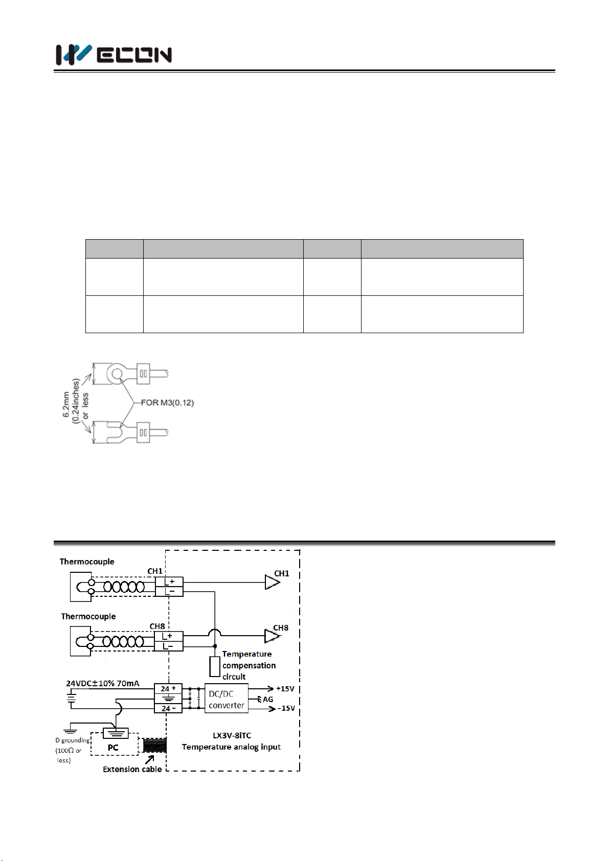
Use the crimp terminals that meet the dimensional
requirements showed in the left figure.
Apply 0.5 to 0.8 N.m (5 to 8 kgf.cm) torque to tighten the
terminals against disoperation.
Wire only the module terminals in this manual, keep
others blank.
(1) The temperature compensation
cable connected to
thermocouple is as follows:
Type K: DX-G, KX-GS, KX-H,
KX-HS, WX-G, EX-H, VX-G
Type J: JX-G, JX-H
Type S: SC-G, SC-H
Type N: NC-G,NC-H
Type E: EX-G, EX-H
Type T: TX-G, TX-H
Type B: BC-G, BC-H
Type R: RC-G, RC-H
error, communication error or the power supply of acquisition board error; be off when the
acquisition board is not calibrated.
COM Lamp: Be always on when digital transmission is normal; be off when the acquisition
board is powered off or fails to communicate with the communication board.
24V Lamp: Be always on when connected to external power supply.
Channel Lamp: Be always on when the temperature is normal; be off when the channel is
closed; flash in case of over-limit temperature, hardware error, communication error or power
error.
3. Wiring
2 WECON Technology Co., Ltd.

LX3V-8iTC
Items
Instructions
Environmental indicators (not including the
following intentions)
Same as LX series PLC unit
Isolation Voltage
500VAC for 1 minute (between all terminals
and ground)
Items
Instructions
Analog circuit
24VDC ±10%,50mA
Digital circuit
5V DC, 90mA (From main unit's internal power supply)
For line impedance per ohm, the compensation cable indicates that it is 0.12 ° C above the
actual value. Check the line impedance before use, and the long compensation cables are
susceptible to noise, so compensating cables shorter than 100 meters are recommended.
(2) The ground terminal, which connects LX3V-8iTC and the main unit, uses the 3rd level grounding
on the main unit.
(3) The 24V built-in power supply of the programmable controller can be used as the power supply
for this unit.
Precautions when wiring:
1) Before installation or wiring, make sure to cut off the external power supply of each phase, for
it may cause electric shock or equipment damage if the power supply is not cut off.
2) Make sure to interlock external loads outside PLC and LX3V and through the PLC program, for it
may be dangerous when they are connected simultaneously.
3) Connect the LX3V-8iTC and PLC power supply properly according to the instructions in this
manual. If the AC power is connected to the DC I / O terminal or the DC power supply terminal,
the PLC may be destroyed.
4) Do not connect external wiring to the terminals not used on LX3V-8iTC and PLC, for this
connection may damage the device.
4. Installation Instructions
4.1 Environmental indicators
4.2 Power indicators
3 WECON Technology Co., Ltd.

LX3V-8iTC
Items
Celsius (oC)
Fahrenheit (oF)
Get two kinds of readable data oC and oF by reading appropriate buffer memory.
Input signal
Thermocouple: Type K, J, T, E, N, B, R, S (use each channel arbitrarily), totally 8
channels as signal input source.
Rated
temperature
range
Type K
from -200 oC to 1372 oC
Type K
from -328 oF to 2501 oF
Type J
from -210 oC to 600 oC
Type J
from -346 oF to 1112 oF
Type T
from -200 oC to 400 oC
Type T
from -328 oF to 752 oF
Type E
from -200 oC to 1000 oC
Type E
from -328 oF to 1832 oF
Type N
from -200 oC to 1300 oC
Type N
from -328 oF to 2372 oF
Type B
from 250 oC to 1820 oC
Type B
from 482 oF to 3308 oF
Type R
from -50 oC to 1768 oC
Type R
from -58 oF to 3214.4 oF
Type S
from -50 oC to 1768 oC
Type S
from -58 oF to 3214.4 oF
Numeric
output
Type K
from -2000 to 13720
Type K
from -3280 to 25010
Type J
from -2100 to 6000
Type J
from -3460 to 11120
Type T
from -2000 to 4000
Type T
from -3280 to 7520
Type E
from -2000 to 10000
Type E
from -3280 to 18320
Type N
from -2000 to 13000
Type N
from -3280 to 23720
Type B
2500 to 18200
Type B
4820 to 33080
Type R
from -500 to 17680
Type R
from -580 to 32144
Type S
from -500 to 17680
Type S
from -580 to 32144
12-bit conversion, stored as 16-bit binary complement
Measurement
accuracy
Type K
0.4
o
C
Type K
0.72 oF
Type J
0.3
o
C
Type J
0.54 oF
Type T
0.4
o
C
Type T
0.72 oF
Type E
0.25 oC
Type E
0.54 oF
Type N
0.52 oC
Type N
0.72 oF
Type B
The average accuracy of
B-type: 2.09 oC,
The average accuracy for
below 1000 oC: 2.97 oC
The average accuracy for
above 1000 oC: 1.64 oC
Type B
The average accuracy of
B-type: 3.762 oF,
The average accuracy for
below 1832 oC: 5.346 oF
The average accuracy for
above 1832 oC: 2.952 oF
Type R
The average accuracy of
R-type: 1.53 oC,
The average accuracy for
below 800 oC: 1.87 oC
The average accuracy for
above 800 oC: 1.32 oC
Type R
The average accuracy of
R-type: 2.754 oF,
The average accuracy for
below 1472 oC: 3.366 oF
The average accuracy for
above 1472 oC: 2.376 oF
Type S
The average accuracy of
Type S
The average accuracy of
4.3 Performance specification
4 WECON Technology Co., Ltd.

LX3V-8iTC
S-type: 1.72 oC,
The average accuracy for
below 800 oC: 2.01 oC
The average accuracy for
above 800 oC: 1.53 oC
S-type: 3.096 oF,
The average accuracy for
below 1472 oC: 3.618 oF
The average accuracy for
above 1472 oC: 2.754 oF
Total accuracy
±(0.5% of the full range ±1 oC) condensation point of pure water: 0 oC /32 oF
Conversion
speed
(240ms±2%) *4 channel (Unused channels are not converted)
Conversion Characteristics: Readings respectively given at the calibration reference point 0 ° C /
32 ° F (0/320). (Subject to the overall accuracy)
Item
Specification
Isolation
It has optical isolation between analog and digital circuits. DC/DC converter is applied
to isolate between this device and MPU. It has signal isolation between each analog
channel.
BFM
Register
W/R
Latch
ed
Defaul
ts
Contents
CH1->CH4
CH5->CH8
Note: Grounding thermocouples are not suitable for use with this unit.
Analog input
Miscellaneous
5. Buffer Memory
5.1 Allocation of Buffer Memory
5 WECON Technology Co., Ltd.

LX3V-8iTC
#0
#40
Channel
type
selection
W/R
O
H0000
Each HEX bit represents a channel
0:K Type(-200~1372 oC) 1:J Type(-210~600 oC)
2:T Type(-200~400 oC) 3:E Type(-200~1000
o
C)
4:N Type(-200~1300 oC) 5:B Type(250~1820 oC)
6:R Type(-50~1768 oC) 7:S Type(-50~1768 oC)
8:Close channel Other: Reserved
For example: when # BFM40 is set as H8721, it
indicates that CH8 is off, CH7 is S Type, CH6 is T
Type, and CH5 is J Type.
#1->#4
#41->#44
Average
filter
constant
R O 8
The average number of samples used to calculate.
Set to 1 for high-speed sampling. The setting
range is 1 ~ 256.
#5->#8
#45->#48
Average
temperat
ure oC
R X 0
The average value of various temperatures in unit
of 0.1 degrees Celsius
#9->#12
#49->#52
Current
temperat
ure oC
R X 0
The current value of various temperatures in unit
of 0.1 degrees Celsius
#13->#16
#53->#56
Average
temperat
ure oF
R X 0
The average value of various temperatures in unit
of 0.1 degrees Fahrenheit
#17->#20
#57->#60
Current
temperat
ure oF
R X 0
The current value of various temperatures in unit
of 0.1 degrees Fahrenheit
#21->#25
#61->#65
Cold-end
temperat
ure
R X 0
The cold-end value of various temperatures in unit
of 0.1 degrees Fahrenheit
#26
#66
Cold-end
mode
setting
W/R
O
-
Cold-end mode read setting: Set 1 channel for
every 4 bits;
0: Read the internal cold-end temperature
1: Read the external CU50 cold-end temperature
Input data must be hexadecimal, only support to
input 0 or 1. Other input value is invalid, and the
value of BFM26 (BFM66) shows the allowed one
by last input.
Among which, 26 controls the first 4 channels, and
6 WECON Technology Co., Ltd.

LX3V-8iTC
66 controls the last 4 channels.
#27
#67
Cold-end
mode
selection
W/R
O
-
Cold-end mode selection, set 1 channel for every
4 bits;
0: Built-in cold end;
1: external cold end;
2: freezing cold end
Input data must be hexadecimal, only support to
input 0, 1 or 2. Other input value is invalid, and
the value of BFM26 (BFM66) shows the allowed
one by last input.
Among which, 27 controls the first 4 channels, and
67 controls the last 4 channels.
The control of BFM26 (BFM66) and BFM27
(BFM67) do not affect each other.
#28
#68
Error
latch
R X 0
The value range is incorrectly latched
#29
#69
Error
code
- - 0
Error state
#30
#70
Identifica
tion code
- - -
Identification number(K2038)
#31
#71
Version
number
- - -
Communication board software version number
#32
#72
Version
number
- - -
Acquisition board software version number
#33->#39
#73->#79
Reserve
- - -
Reserve
Note: Symbol Description
O represents maintainer line, X represents non-maintainer line, R represents readable data, W
represents writable data.
7 WECON Technology Co., Ltd.
LX3V-8iTC
5.2 Description of Buffer Memory (BFM)
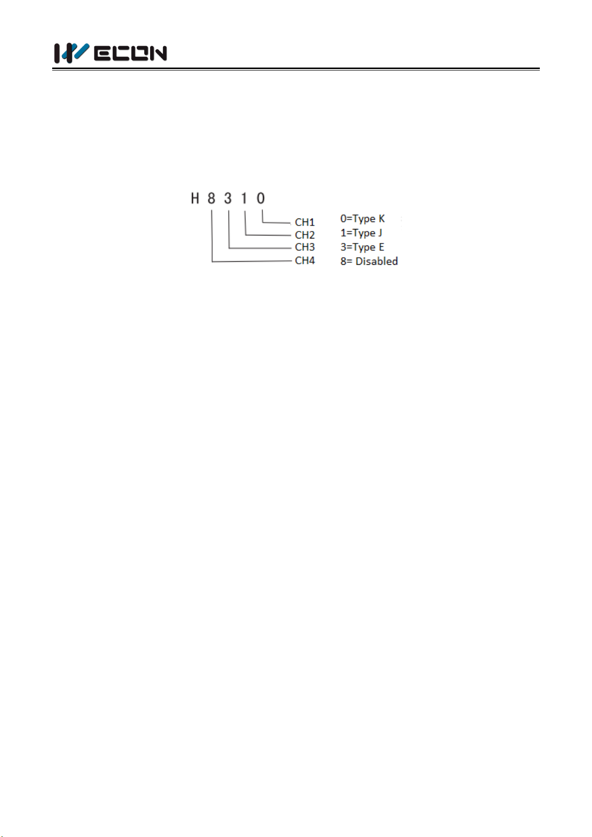
1) Buffer memory BFM # 0 / BFM # 40: select 8 types of thermocouples
Use to select 8 types of thermocouples for each channel. Each bit of the 4-bit hexadecimal
number corresponds to one channel, BFM # 0 sets 1 to 4 channels and BFM # 40 sets 5 to 8
channels. For example, BFM # 0 sets as follows:
The A / D conversion time per channel is 240 ms. When a channel is set to "8" (not used), the
corresponding channel does not perform A / D conversion, so the total conversion time is
reduced. In the above example, the conversion time is as follows:
240 ms (conversion time per channel) * 3 channels (channels in use) = 720 ms (total usage
time)
2) Buffer register BFM # 1-BFM # 4, BFM # 41-BFM # 44: number of the averaged temperature
readings
The averaged sample values of the 1st to 4th channels are assigned to BFM # 1 to BFM # 4, and
the averaged sample values of the 5th to 8th channels are assigned to BFM # 41 to BFM # 44.
Only the range of 1 to 4096 is valid. The overflowed value will be ignored. Use 8 as the default
value.
Some of the most recently converted readable values are averaged to give a smoothed readable
value. The average Celsius data is stored in BFM # 5 to BFM # 8 and BFM # 45 to BFM # 48. The
average Fahrenheit data is stored in BFM # 13 to BFM # 16 and BFM # 53 to BFM # 56.
3) Current temperature
Used to save the current value of input data in the unit of 0.1 ° C or 0.1 ° F. BFM # 9 to BFM # 12
and BFM # 17 to BFM # 20 store the current values of the 1st to 4th input data, and BFM # 49 to
# 52 and # 57 to # 60 store the current values of the 5th to 8th input data.
4) Cold-end compensation
BFM # 27 / BFM # 47 sets the thermocouple cold-end compensation mode. Each bit of the 4-bit
hexadecimal number corresponds to one channel, BFM#27 sets 1 to 4 channels, and the last bit
sets channel 1. BFM # 47 sets 5 to 8 channels, and the last bit sets channel 5.
8 WECON Technology Co., Ltd.

LX3V-8iTC
b15-b8
b7
b6
b5
b4
b3
b2
b1
b0
Not
used
High
Low
High
Low
High
Low
High
Low
CH4/CH8
CH3/CH7
CH2/CH6
CH1/CH5
Bit for error state
ON
OFF
b0: error
If any of b1 to b3 is ON, the
error channel A / D stops
conversion.
No error
b1: reserve
Reserve
Reserve
b2: power failure
24VDC power failure
Normal power
b3: hardware
error
A / D converter or other
hardware failure
Normal hardware
b4 to b9: reserve
Reserve
Reserve
b10: data range
error
Data output / analog input
value is out of specification
Normal data output
Built-in cold-end mode: adopt module built-in NTC sensor to collect the indoor temperature for
thermocouple cold-end compensation, without additional wiring.
Freezing cold-end mode: place the cold end of TC thermocouple in the ice-water mixture.
5) Buffer memory BFM # 28 / BFM # 68: Digital range error latch
b10 (digital range error) of BFM # 29 / BFM # 69 determines whether the measured
temperature is within the unit allowable range.
BFM # 28 latches the error state of each channel and can be used to detect if the thermal
resistance is off.
Low: latch ON when the temperature measurement drops and is below the minimum
measurable temperature limit.
High: turn on ON when the temperature measurement rises and is above the maximum
temperature limit, or when the thermal resistance is off.
If an error occurs (disconnect the sensor), the temperature data before error is latched. If the
measured return value is within valid range, the temperature data returns to normal operation.
6) BFM29 / BFM69: Error state
9 WECON Technology Co., Ltd.

LX3V-8iTC
b10: average
error
The value of selected average
result is out of the available
range, refer to BFM # 1 to # 4
Average normal (within 1 to
4096)
b12 to b15:
reserve
Reserve
Reserve
7) ID buffer memory BFM # 30 / BFM # 70
Use FROM instruction to read the ID code or ID number of special function module from the
buffer memory BFM # 30 or BFM # 70. The ID code of LX3V-8iTC unit is K2038.
Use this ID code in the user program of programmable controller to confirm this special
function module before transmitting / receiving data.
6. System Block Diagram
7. Sample Program
In the program shown below, the LX3V - 8iTC module occupies the location of special module 2 (this
10 WECON Technology Co., Ltd.

LX3V-8iTC
is the third closest to the programmable control unit). The average number is 4. The average values
of input channels CH1 to CH4 in °C are respectively stored in data registers D0 to D3. The average
value of input channels CH5 to CH8 in °C is respectively stored in data registers D4 to D7.
1) Set the thermocouple type and write H8310 into BFM#0 and BFM#40 of N0.2 module. CH1: K
type; CH2: J type; CH3: E type; CH4: not used; CH5: K type; CH6: J type; CH7: E type; CH8: not
used.
2) Set the thermocouple cold-end compensation mode and write H1200 into BFM # 27 and BFM #
67 of the N0.2 module. CH1: built-in cold-end mode; CH2: built-in cold-end mode; CH3: freezing
cold-end mode; CH4: external cold-end mode. CH5: built-in cold-end mode; CH6: built-in
cold-end mode; CH7: freezing cold-end mode; CH8: external cold-end mode.
3) BFM # 30 -> (D10) of the module NO.2, When (K2038) = (D10), M1 = ON, that is, when the ID
code is K2038, M1 = ON.
The initialization step checks if the special function module in position 2 is LX3V - 8iTC, that is, if
its unit ID code is K2038 (BFM # 30 / BFM # 70). This step is optional, but it provides a way for
software to check if the system is properly configured.
4) This step provides optional monitoring of the error buffer memory (# 29) of the LX3V - 8iTC. If
there is an error in LX3V-8iTC, b0 of BFM # 29 will be set to ON. This can be read out by this
program step and output as a device in LX3V programmable controller (M3 in this case).
Additional error devices can be output in the same way, such as b10 of BFM # 29.
11 WECON Technology Co., Ltd.

LX3V-8iTC
5) This step sets the average number of samples in LX3V - 8iTC and reads back the average
Fahrenheit value of samples. For example, "TO" instruction sets the average number of samples
and "FROM" instruction reads the data in LX3V - 8iTC buffer memory. The average number of
samples from CH1 to CH4 is set to 4, and the average number of samples from CH5 to CH8 is set
to 6. The data of BFMs # 5 to # 8 and BFMs # 45 to # 48 are then respectively stored into the
PLC data registers D0 to D3 and D4 to D8.
8. Diagnosis
8.1 Initial Check
1) Check if the input / output wiring and / or extension cable are connected to the LX3V-8iTC
analog special function module.
2) Check does not violate the system configuration rules of LX3V, for example: the number of
special function modules cannot exceed 8, and the total number of system I / O points cannot
exceed 256.
3) Make sure the correct operating range is selected for the application.
4) Check if there is power overload in the 5V or 24V power supply. Remember: the load change of
the LX3V unit or active expansion unit varies depending on the number of expansion modules
or special function modules connected.
5) Set the LX3V main unit MPU to RUN state.
12 WECON Technology Co., Ltd.

LX3V-8iTC
8.2 Error Check
If the special function module LX3V - 8iTC does not operate normally, check the following items.
1) Check the state of power LED lamp:
On: Expansion cable is properly connected;
Off: Check the connection of expansion cable;
Flash: check the external 24V connection.
2) Check the external wiring
Check the state of "24V" LED lamp.
On: LX3V - 8iTC is normal, 24V DC power supply is normal;
Otherwise: Possible 24V DC power failure, LX3V - 8iTC failure if power supply is normal.
3) Check the state of "A / D" LED lamp (COM lamp)
On: A / D conversion is operating normally
Otherwise: Check buffer memory BFM # 29 (error state). If any bit (b2 and b3) is in ON state,
that is why the A / D LED lamp goes out.
8.3 Check the Number of Special Function Modules
Other special modules that use FROM / TO instruction, such as analog input modules, analog output
modules, and high-speed counting modules, can be directly connected to the main unit of LX3V
programmable controller or to the right of other expansion modules or units. Depending on the
close extent to the main unit, each special module is numbered from 0 to 15. Up to 16 special
modules can be connected.
13 WECON Technology Co., Ltd.

LX3V-8iTC
9. EMC Measures
Electromagnetic compatibility or EMC must be considered before using LX3V - 8iTC.
If some form of cable protection is used, "shield " must be connected to the ground
terminal, as shown in section 3.
Due to the very weak analogue signal, it will lead to EMC noise error if EMC precautions are not
taken seriously, with error value up to ± 10% of actual value. This situation is very bad. Users can get
the desired operation in normal allowable range only by taking good precautions.
EMC measures should include the selection of high quality cables that are well wired to avoid
potential sources of noise.
In addition, signal averaging is recommended to reduce the "puncture" effect of random noise.
Version: V1.0.0
Date: Aug 2018
14 WECON Technology Co., Ltd.
 Loading...