


WECO Electrical Connectors Series 93-FL Data Sheet
21
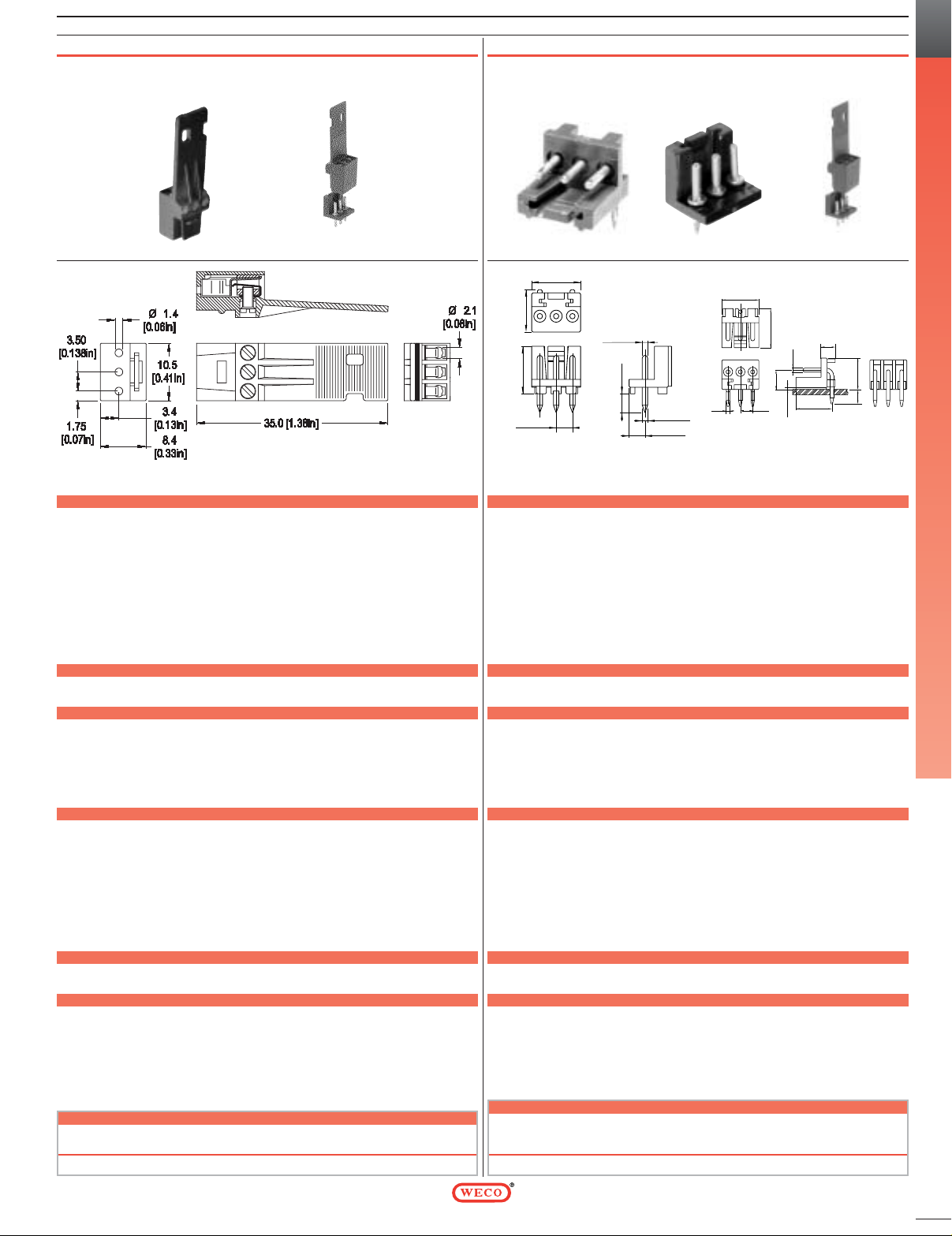
Series 93-FL
Types 930-HFL (-DS)
3.5 mm spacing• 3 poles
Dimensions: mm (in.) When locating connector, allow 0.5 mm clearance around it for process-induced variations.
DESCRIPTION
These products were created for the broadcasting and video production industries
but can be used in all applications where a small wire gauge is needed. Series 930HFL features a handle to simplify vertical in-line insertion and removal and is
designed to provide strain relief for the terminated wires. The plug and header are
designed to prevent accidental separation of the two parts.
Horizontal and vertical plug-in versions are available, both versions feature 3 poles
and 3.5 mm center to center spacing.
•
Plug
•
Plug-In Direction and Wire Entrance Parallel to PCB when plugged with 930-HSL
•
Plug-In Direction and Wire Entrance Perpendicular to PCB when plugged with
931-HSL
TECHNICAL DATA
Center to Center Spacing: 3.5 mm (0.138 in.) Wire Stripping length: 5 mm (0.20 in.)
Nominal Cross Section: 0.75 mm
2
(1162 mils2)
APPROVAL INFORMATION
Screw
Rating Current Voltage AWG Application Tightening
(A) (V) Group Torque
2
File No.: E69841 UL 6 300 28-18 B,C max. 2.0 lbfin.
3
File No.: LR24322 CSA 6 300 28-18 B max. 0.2 Nm
DS version is CSA certified for 28-20 AWG.
Rated Impulse Withstand Voltage:
2500 V
MATERIAL
MOLDING: Polyamide, self extinguishing to UL 94, V-0, grey
TEMPERATURE LIMITS: Short time: 200°C (390°F)
Continuous: RTI 105°C (221°F)
Low limit: -40°C (-40°F)
Comparative Tracking Index: CTI > 600
Oxygen Index Rating: 31%
Terminal Body: nickel plated copper alloy
Wire Protector: nickel silver
Contact Spring: tin plated copper alloy
Screw: yellow chromate passivated, zinc plated, steel, M2
ACCESSORIES
•
BST Self Adhesive Marking Strips. Consecutively numbered.
•
LST Single Pins.
OPTIONS
See How to Order. If more than one option is required, please separate each option with a dash (-).
SM: Special Marking (please provide sketch)
G05: Gold Plating (5 micro inches)
G30: Gold Plating (30 micro inches)
S30: Silver Plating (30 micro inches)
(Plated components: contact spring)
Plug-in Screw Connector Systems for Printed Circuit Boards
930-HFL (-DS)
Series 93-FL
Types 930 / 931-HSL
3.5 mm spacing• 3 poles
Dimensions: mm (in.) When locating connector, allow 0.5 mm clearance around it for process-induced variations.
DESCRIPTION
These products were created for the broadcasting and video production industries
but can be used in all applications where a small wire gauge is needed. The plug
and header are designed to prevent accidental separation of the two parts.
Horizontal and vertical plug-in versions are available, both versions feature 3 poles
and 3.5 mm center to center spacing.
•
Header
•
Plug-In Direction and Wire Entrance Parallel to PCB when plugged with 930-HFL
(-DS)
(for 930-HSL only)
•
Plug-In Direction and Wire Entrance Perpendicular to PCB when plugged with
930-HFL (-DS)
(for 931-HSL only)
TECHNICAL DATA
Center to Center Spacing: 3.5 mm (0.138 in.) Recommended Hole Ø in PCB: 1.3 mm (0.051 in.)
APPROVAL INFORMATION
Rating Current Voltage Application
(A) (V) Group
2
File No.: E69841 UL 6 300 B,C
3
File No.: LR24322 CSA 6 300 B
MATERIAL
MOLDING: Polyamide, self extinguishing to UL 94, V-0, grey
TEMPERATURE LIMITS: Short time: 200°C (390°F)
Continuous: RTI 105°C (221°F)
Low limit: -40°C (-40°F)
Comparative Tracking Index: CTI > 600
Oxygen Index Rating: 31%
Solder Pin: tin plated copper alloy, 1.0 mm (0.04 in.)
ACCESSORIES
•
BST Self Adhesive Marking Strips. Consecutively numbered.
•
LST Single Pins.
OPTIONS
See How to Order. If more than one option is required, please separate each option with a dash (-).
G05: Gold Plating (5 micro inches)
G30: Gold Plating (30 micro inches)
S30: Silver Plating (30 micro inches)
(Plated components: solder pin)
930-HSL / 03 931-HSL / 03
TERMINAL BLOCKS FOR PRINTED CIRCUIT BOARDS
A
930-HFL
||
/03-
|
HOW TO ORDER
WIRE PROTECTOR:
with: - DS
OPTIONS:
SM, G05, G30, S30
93
||
-HSL/03-
|
HOW TO ORDER
WIRE DIRECTION:
horizontal: 0
vertical: 1
OPTIONS:
G05, G30, S30
10.5 (.41)
8.4 / (.33)
- or -
9.1 (.36)
11.1 (0.44)
3.50 (0.138)
Ø1.1 (0.04")
1.1 (.04)
- or -
4.1 (.16)
3.4 (0.13)
Ø1.1 (.04)
- or -
Ø1.15 (.045)
931-HSL
5.5
(.22)
Ø0.5 (.02)
8.9 (.35)
10.5 (.41)
Ø1
(Ø.04)
3.5
(1.38)
11.1 (.44)
Ø1.15
10.2 (.40)
4
(.16)
4.0
(.16)
930-HSL
One possible variation of
assembly
One possible variation of
assembly