

TECHNIC AL D AT A SHEET
Terminal body
Tin plated brass
•
Longer solder pins up to 95 mm
[2] Acc. to IEC 60947-7-4 und IEC 60947-1
© Copyr
ightbyWECO
Pleas e r ef er to our websi te for t h e full d i sc l ai m e r.
974(-DS)
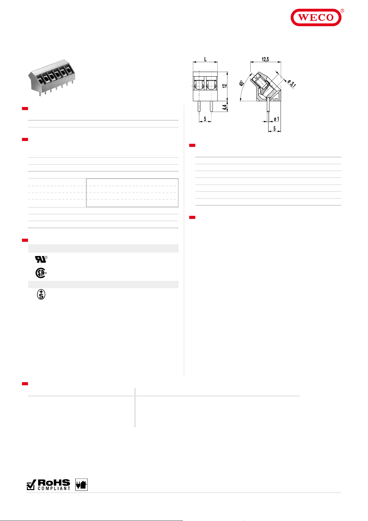
PCB connector
Screw connection 45°- angle to PCB
GENERAL INFO RMATION
Pitch 5 mm
No. of poles 2 - 26
TECHNICAL DATA
Clamping Range solid / stranded / AWG
without wire protector 1 - 6 mm² / 1 - 2,5 mm² / 16 - 12 AWG
with wire protector 0,75 - 4 mm² / 0,75 - 2,5 mm² / 18 - 12 AWG
Rated Cross Sec tion 2,5 mm²
Wire Stripping Length 6,5 mm ± 0,5 mm
Overvoltage Category III III II
Pollution Severity Level 3 2 2
Rated Voltage 250 V 320 V 630 V
Rated Impulse Voltage 4 kV 4 kV 4 kV
Rated Current 24 A
Hole in PCB ø 1,3 mm
Torque 0,5 Nm
APPROVALS
Current [A] Voltage [V] Group AWG [Nm]
20
10
20
10
Current [A] Voltage [V] mm²
24 250 2,5 [2]
300
300
300
300
B
D
B
D, E
22-12 [1]
22-12 [1]
26 - 12
26 - 12
0,51
0,51
0,51
0,51
MATERIAL
Moulding PA, grey, V-0
Comparative Tracking Index CTI ≥ 600
Insulating Group I
Temperature Range -40°C up to 100°C
Screw M3; zinc plat ed s t eel, clear passivat ed
Solder pin ø 1 mm; tin plated copper
Wire protector Tin plated tin bronze
OPTIONS / ACCESSORIES
Consecutive number ing
•
Special marking according t o drawing
•
Self-adhesive mark ing s trip BST-5,00
•
Special wire protect or for very thin conduc tors
•
Version with raised f oot of 1,6 mm
•
With base plate, s ee 974-BP
•
With extended sc rew guide (974-C)
•
[1] Min No. 26 AWG for factory-wiring only
CONFIGURATIONS
Poles Part number Article number Part number Article number Length (L) Pac k aging PU
2 974/02 10.874.002 974-DS/02 20.874.002 10,00 mm Box 250
3 974/03 10.874.003 974-DS/03 20.874.003 15,00 mm Box 250
4 974/04 10.874.004 974-DS/04 20.874.004 20,00 mm Box 200
5 974/05 10.874.005 974-DS/05 20.874.005 25,00 mm Box 100
6 974/06 10.874.006 974-DS/06 20.874.006 30,00 mm Box 100
07.19
Information pro vide d in t his docu men t ma y be c hange d w it hou t p rior not ice.
All rightsreserved.WECO®is a brandofthe WECO Group.
 Loading...