

TECHNIC AL D AT A SHEET
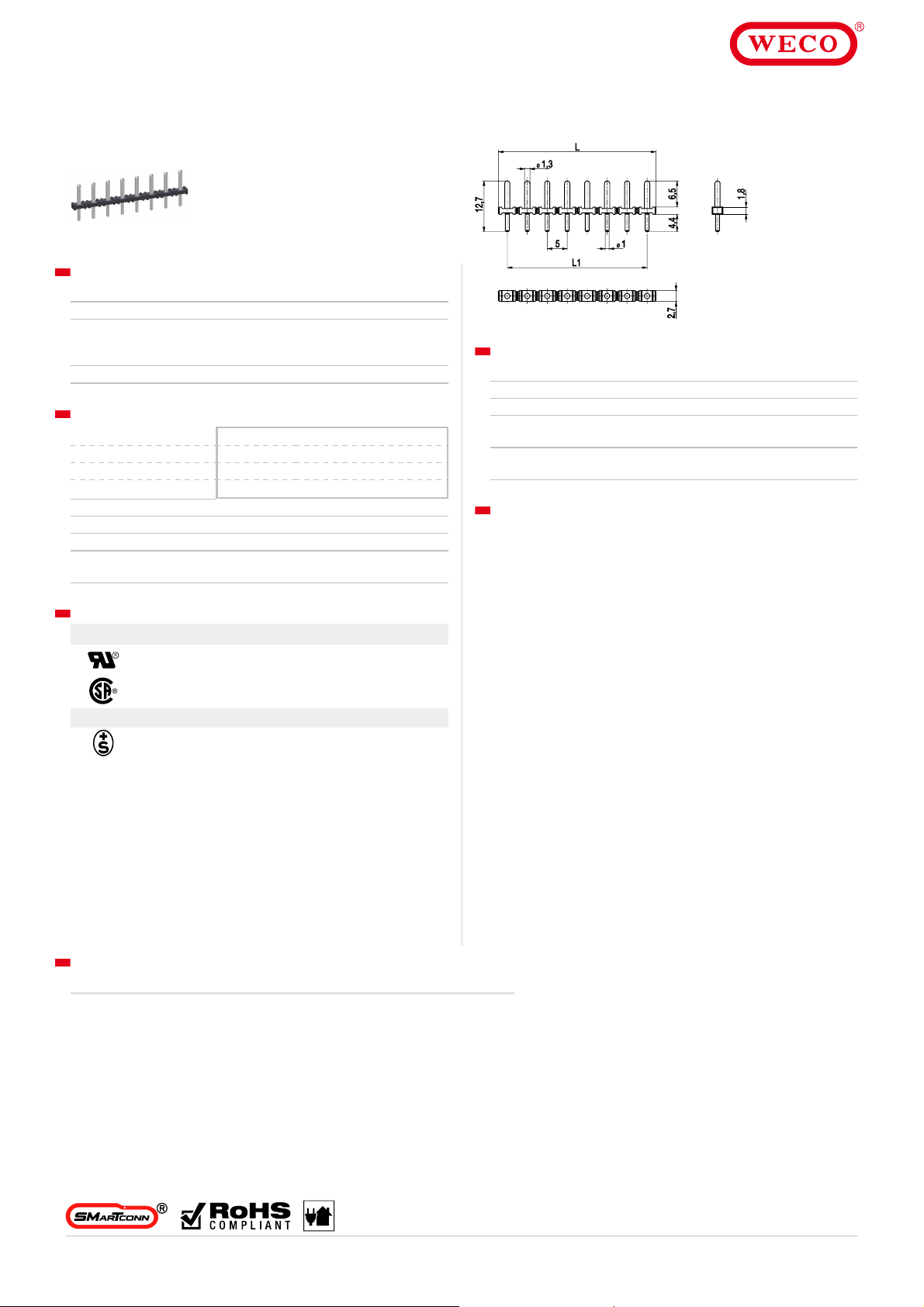
L1 = (number of poles -
-40°C up to 120°C; reflow solder temperature peak
max. 255°C acc . t o DIN EN 61760-1
manufacturer’s Cat. No. 120-W-111 terminal blocks. Above headers with 1.1 mm
or 1.3 mm dia. pins are rated 12A max. with 115-F-111, 115-F-211 and 115-F-118
© Copyr
ightbyWECO
Pleas e r ef er to our websi te for the f ul l di sclai me r.
971-SLR
Pin strip
Soldering area ø 1 mm ; plug-in area ø 1,3 mm
GENERAL INFO RMATION
Pitch 5 mm
No. of poles 2 - 12
Usable with plug connector of series 115-F, 950-F L-D S,
950-TFL-DS, 950-NAF-D S, 950-GFL-DS,
950-NLFL-DS, 950-RFL-DS, 970-FBW-FU(-DS)
Additonal Informat ion Pin strip is suitable for reflow soldering
TECHNICAL DATA
Overvoltage Category III III II
Pollution Severity Level 3 2 2
Rated Voltage 250 V 320 V 630 V
Rated Impulse Voltage 4 kV 4 kV 4 kV
Rated Current 10 A
Soldering process Wave solder & reflow s older
Hole in PCB ø 1,3 mm
PCB thickness Wave solder max. 1,6 mm; reflow solder 1,6 - 3,2
mm
1) x pitch
MATERIAL
Moulding PA HT, black, V-0
Comparative Tracking Index CTI ≥ 600
Insulating Group I
Temperature Range
Solder pin ø 1,3 mm (plug-in area) / ø 1,0 mm (soldering
area); tin plated brass
OPTIONS / ACCESSORIES
Other plug pin lengths on request
•
Other solder pin surfac es on request
•
[1] Above headers with 1.0 or 1.1 mm dia. pins are rated 12A max. wit h
APPROVALS
Current [A] Voltage [V] Group AWG [Nm]
10 [1] 300 B
10 [1] 300 B
Current [A] Voltage [V] mm²
13,5 250 [2]
CONFIGURATIONS
Poles Part number Article number Length (L) Pac k aging PU
2 971-SLR/02 12.893.811 9,50 mm Box 1000
3 971-SLR/03 13.893.811 14,50 mm Box 500
4 971-SLR/04 14.893.811 19,50 mm Box 500
5 971-SLR/05 15.893.811 24,50 mm Box 250
6 971-SLR/06 16.893.811 29,50 mm Box 250
further number of poles on r equest
terminal blocks .
[2] Acc. to IEC 60947-7-4 und IEC 60947-1
07.19
Information pro vide d in t his docu men t ma y be c hange d w it hou t p rior not ice.
All rightsreserved.WECO®is a brandofthe WECO Group.
 Loading...