

WECO Electrical Connectors 308-PA/..-101 Data Sheet
308-PA/..-101
03.18
6
0,8
7
7
4,8
6
0,8
7
7
4,8
Pitch
11 mm
Moulding
PA, natural, V-2
Insulating Group
IIIa
Tab
Zinc plated st eel
Square washer
M4; Zinc plat ed s t eel
[1] Per pole two w ires of identical cross -s ection can be connected. T his is valid up
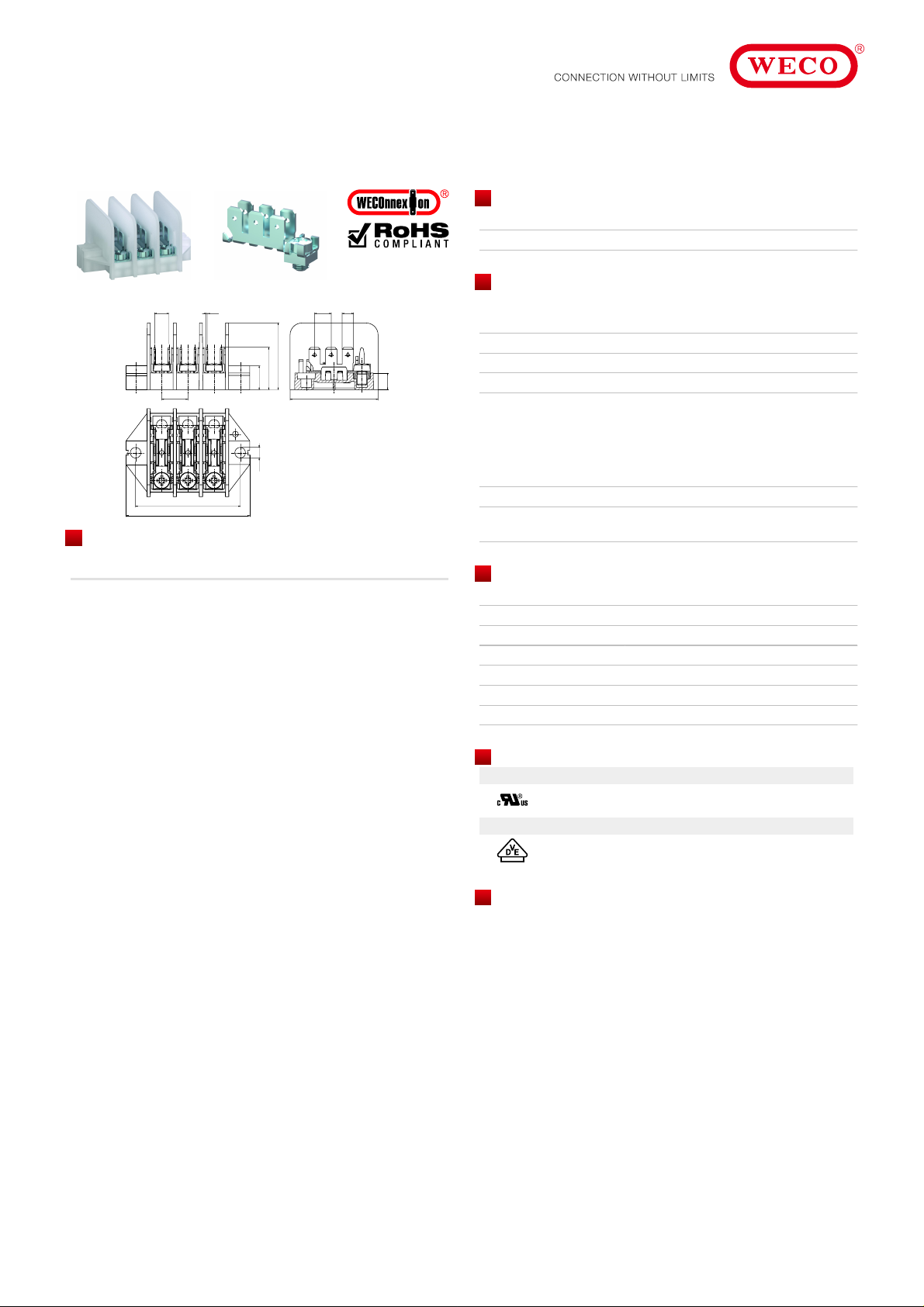
Distribution block
Tab connections 6 x 4,8 & Screw connecti on; vert ical
28
28
17,8
17,8
10
10
11
11
ø 4,5
ø 4,5
L - 8
L - 8
L
L
Part Numbers
No. of
308-PA/.. -101 Length PU
poles
1 11.885.101 30 250
2 12.885.101 41 200
3 13.885.101 52 200
4 14.885.101 63 100
5 15.885.101 74 100
6 16.885.101 85 100
7 17.885.101 96 100
8 18.885.101 107 50
10 20.885.101 129 50
12 22.885.101 151 50
further number of poles on request
37
37
General Information
No. of poles 1 - 16
Technical Data
Clamping Range solid / flexible / AWG
0,5 - 2,5 mm² / 0,5 - 2,5 mm² / 20 - 14 AWG [1][2]
Rated Cross Section 1,5 mm² [3]
Wire Stripping Length 7 mm ± 0,5 mm
Rated Insulation Voltage 450 V acc. to EN 60998-1
Rated Current acc. to DI N EN 61210:
7,5 A with recept able 4, 8; wire 1 mm²
12 A with receptable 4, 8; wire 1,5 mm²
15 A with receptable 4, 8; wire 2,5 mm²
17,5 A with screw connection; wire 1,5 mm²
Torque 1,7 Nm
Other specifications Screw terminals are generally suitable for wires
with identical w ire type / cross-section.
Material
Comparative Tracking Index CTI 250
Temperature Range RTI Str 90°C
Screw M4; Zinc plat ed s t eel, blue passivated
Approvals
Current [A] Voltage [V] Group AWG [Nm]
15
10
Current [A] Voltage [V] [mm²]
17,5 450 1,5
300
300
BD16 - 14 [4]
16 - 14 [4]
1,7
1,7
Options / Accessories
Consecutive number ing
•
Special marking according t o drawing
•
Fixed marking in t he t ool on request
•
Jumper VB-308
•
to 1,5 mm² / 16 AWG.
[2] Ferrules are required when using flexible or mult i-stranded wires
[3] Screw connec tion
[4] AWG specif ications refer to s c rew connections
 Loading...