

Page 1
Installation & Operating Manual
Congratulations On Your Choice
In Purchasing This Webtrol Pump
Its Quality is unsurpassed in material and workmanship and has been factory tested.
If properly installed, it will give many years of trouble free service.
PC Series
CENTRIFUGAL
25IPCC-M
7/08 Edition
Page 2
Introduction 2
Performance / Specifications 3
Exploded View & Parts List 4
Pump Inspection And Handling 5
Pre-Installation 5
Installation 5-6
Location
Mounting
Piping
Electrical Connections 7-9
Start-up Procedure 10
Shaft Rotation
Valves
Priming
Starting
Final Inspection
Trouble Shooting 12
Table Of Contents
Introduction
This manual was prepared to assist the installer and/or operator in understanding the proper method of
installing, operating and maintaining the PC series centrifugal pump. We recommend that you thoroughly
understand the proper installation and start-up procedures, prior to starting the pump. If these procedures are
followed, you will have years of trouble-free service.
1. Read these rules and instructions carefully. Failure to follow them could cause serious bodily injury and/or
property damage.
2. Check your local codes before installing.
3. For maximum safety, this product should be connected to a grounded circuit, equipped with a ground fault
interrupter device.
4. Before installing this product, have the electrical circuit checked by an electrician to make sure it is
properly grounded.
5. Before installing or servicing the pump, BE CERTAIN the pump power source is disconnected.
6. Make sure the line voltage and frequency of the electrical current supply agree with the motor wiring.
If motor is dual voltage type, BE SURE it is wired correctly for your power supply.
7. Complete pump and piping system MUST be protected against below freezing temperature. Failure to do
so could cause severe damage and voids the Warranty.
8. Discharge pressure not to exceed 85 PSI - suction pressure to 36 PSI - with 49 PSI boost.
9. Do not run the pump dry. If it is, there will be damage to the pump seal, and pump components.
10. Do not operate the pump in a flammable and/or explosive atmosphere.
WARNING
Rules For Safe Installation And Operation
- 2 -
Page 3
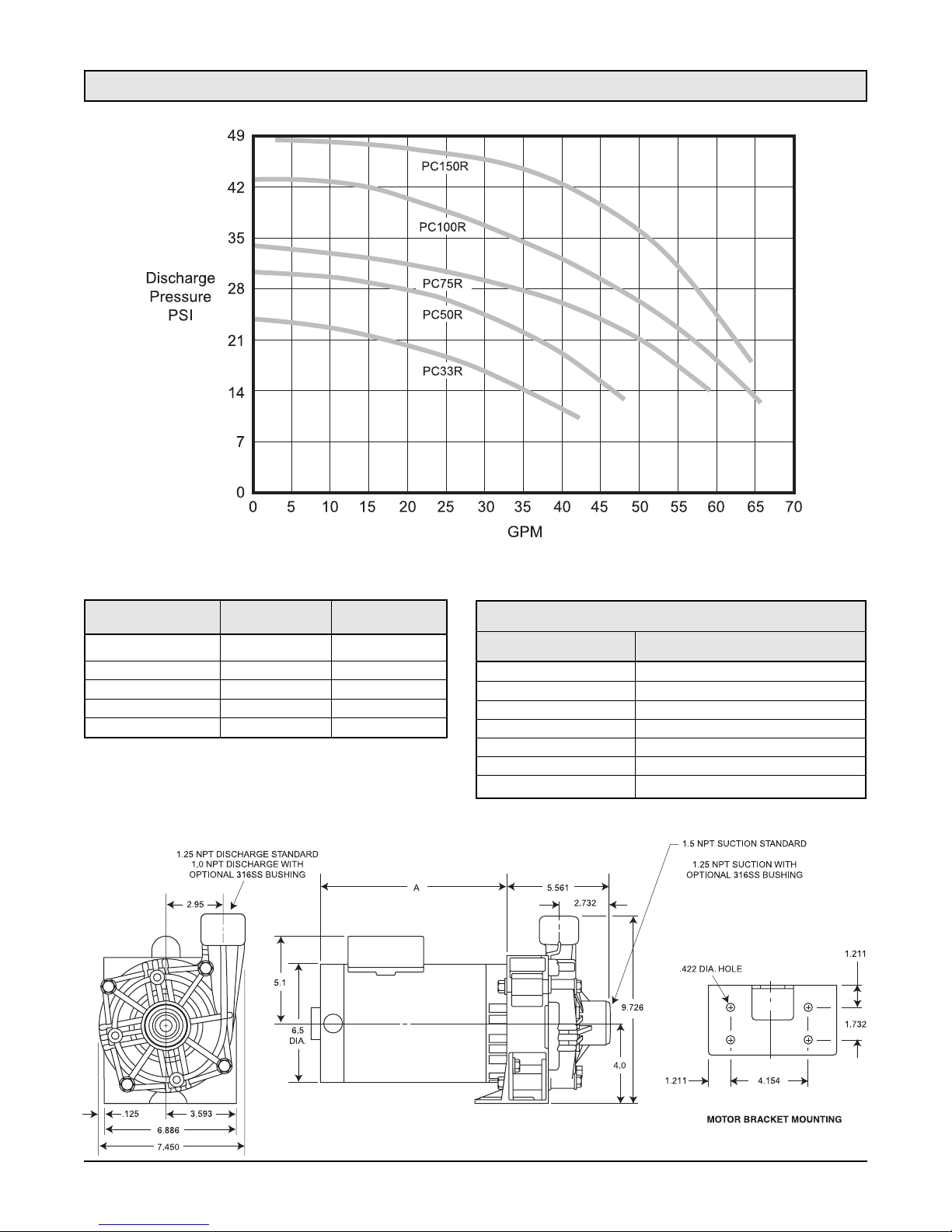
Performance / Specifications
Materials Of Construction
Part Material
Pump Housing Noryl, GFN3 GE Thermoplastic
Motor Bracket Noryl, GFN3 GE Thermoplastic
Impeller (closed type) Noryl, GFN3 GE Thermoplastic
Wear Ring 316SS
Motor Shaft 303SS
Mechanical Seal Carbon/Ceramic
O-Ring Viton
Model Number A (Length) HP
PC33R 9.11 1/2
PC50R 9.11 1/2
PC75R 9.86 3/4
PC100R 10.11 1
PC150R 10.31 1 1/2
1/2 - 1 1/2 HP For Continuous Duty Operation
Motor - The end-mounting motor has no feet, and
is supported by the motor bracket. An open dripproof enclosure is standard with class B insulation.
Single (1) phase ODP motor dimensions for
Emerson motors shown.
- 3 -
Page 4
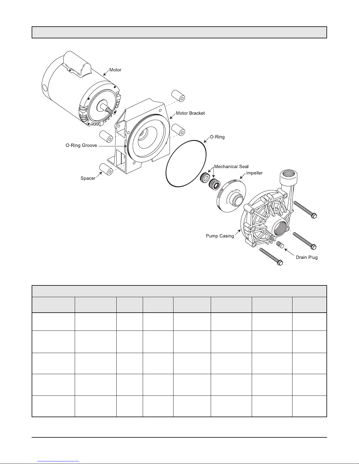
Exploded View
Parts List
Model Number Motor Pump Motor Impeller Mechanical O-Ring Hardware
Casing Bracket Seal Kit
PC33R 10J05-M 20C2 12C2 15C3R 70X130-M 28C126-V K133
PC33R-3PH 10J05-M3PH 20C2 12C2 15C3R-3PH 70X130-M 28C126-V K133
PC50R 10J05-M 20C2 12C2 15C5R 70X130-M 28C126-V K133
PC50R-3PH 10J05-M3PH 20C2 12C2 15C5R-3PH 70X130-M 28C126-V K133
PC75R 10J07-M 20C2 12C2 15C7R 70X130-M 28C126-V K133
PC75R-3PH 10J07-M3PH 20C2 12C2 15C7R-3PH 70X130-M 28C126-V K133
PC100R 10J010-M 20C2 12C2 15C10R 70X130-M 28C126-V K133
PC100R-3PH 10J010-M3PH 20C2 12C2 15C10R-3PH 70X130-M 28C126-V K133
PC150R 10J015-M 20C2 12C2 15C15R 70X130-M 28C126-V K133
PC150R-3PH 10J015-M3PH 20C2 12C2 15C15R-3PH 70X130-M 28C126-V K133
- 4 -
Page 5

Pre-Installation
Installation
Pump Inspection And Handling
When receiving your pump, check to see if the shipment has been damaged in any way or if any parts seem to
be missing. If so, note the damage or shortage on the bill of lading and the freight bill. Make any claims to the
transportation company immediately. Keep all packaging materials until the claim is resolved.
The Webtrol PC Centrifugal pump should remain in the shipping carton until it is ready to be installed.
Do not drop or mishandle the pump prior to installation.
Warning: Never run the pump dry. The internal running surfaces of the pump and mechanical seal require
water lubrication for consistent operation. Allowing the pump to run dry will severely damage pump
and seal.
Do not pump chemicals or corrosive liquids with the pump unless they are compatible with the pump component
materials. (Consult Webtrol for verification at (314) 631-9200) Use with non-flammable liquids.
To avoid internal damage to the pump, do not operate with water temperatures above 180 degrees F.
Pump must be full of liquid before operating. Do not pump dirty water or abrasive liquids. To do so, will cause
the carbon seal face and elastomers in the seal to wear and leak. Mechanical seal materials, compatible with
liquids containing abrasives, are available upon request.
Do not allow the pump or any system component to freeze. To do so may damage the pump and void the
warranty.
Avoid air pockets in suction piping or air will accumulate at the high points making operation difficult.
Locate - The pump as close to the liquid source as possible, so that a short, direct suction pipe may be used.
Place the unit so that it is readily accessible for service, maintenance and allows air to circulate freely around
the motor.
Mount - Unit in a dry location, on a secure base or foundation. This will prevent noise and vibration.
Piping - Should be galvanized, rigid plastic or other suitable pipe that will not collapse when exposed to
suction and discharge pressure. The piping should be as free from turns and bends as possible, as elbows and
fittings greatly increase friction loss. Do not use pipe dope. Use teflon tape if needed.
Pipes must line up and not be forced into position by unions. The inlet (suction) pipe should be at least 1 1/2
inches and preferably one size larger. To reduce friction losses, the number of elbows and fittings should be kept
to a minimum.
Piping should be independently supported near the pump so that no strain will be placed on the pump casing.
Where any noise is objectionable, the pump should be insulated from the piping with rubber connections.
Pump is non-submersible. Keep motor dry at all times. Do not wash or immerse the motor.
- 5 -
Page 6
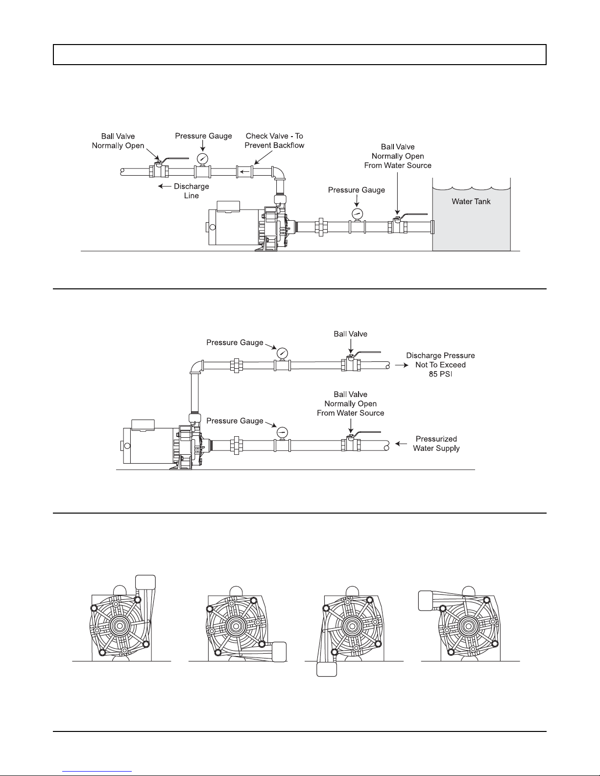
Note: Inlet pipe should be at least one size larger than suction inlet tapping. (1 1/2 NPT)
Figure1 - Connection to a water tank which provides a gravity flow, flooded suction.
Figure 2 - Connection to a pressurized water system.
Figure 3 - The normal position of the discharge is top vertical.
Figure 1
Normal Position
of Discharge
Discharge Rotated
90
o
Clockwise
Discharge Rotated
180oClockwise
Discharge Rotated
270oClockwise
Figure 2
Figure 3
- 6 -
Page 7
Electrical Connections
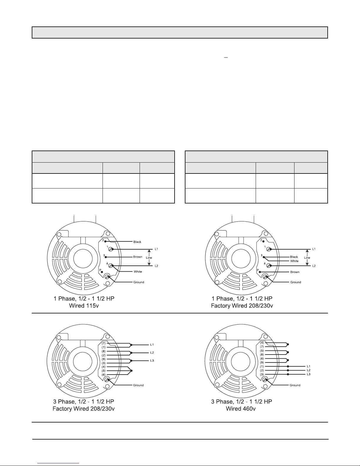
Before wiring the pump to the power source, verify that the voltage of the motor matches the voltage of the
power supply. (See Motor Nameplate) The supply voltage must be within + 10% of nameplate voltage.
Wire the motor according to the diagram shown on the motor nameplate. If the nameplate diagram differs from
the wiring diagram shown in this manual, follow the nameplate diagram.
Install ground wire and maintain this pump in compliance with the National Electrical Code (NEC) or the
Canadian Electrical Code (CEC) and with all local codes and ordinances that apply. Consult your local building
inspector for local code information.
The motors used on the PC Series Centrifugal Pump are manufactured by Emerson, Bluffton or Baldor. Both 1
phase and 3 phase motors are factory wired for 230 volts.
If the supply voltage for a 1 phase motor is 115 volts refer to the wiring diagrams shown below to properly rewire
the motor.
- 7 -
Emerson 3 Phase ODP Motor
Catalog Number See Figure HP
10J05-M3PH 5 1/2
10J07-M3PH 5 3/4
10J010-M3PH 5 1
10J015-M3PH 5 1 1/2
Emerson 1 Phase ODP Motor
Catalog Number See Figure HP
10J05-M 4 1/2
10J07-M 4 3/4
10J010-M 4 1
10J015-M 4 1 1/2
Emerson Motors - Connection Diagrams
Figure 4
Emerson Motors - Connection Diagrams
Figure 5
If the supply voltage is 460 volts, refer to the motor wiring connections shown in (Figure 5) to properly rewire
the motor.
Page 8
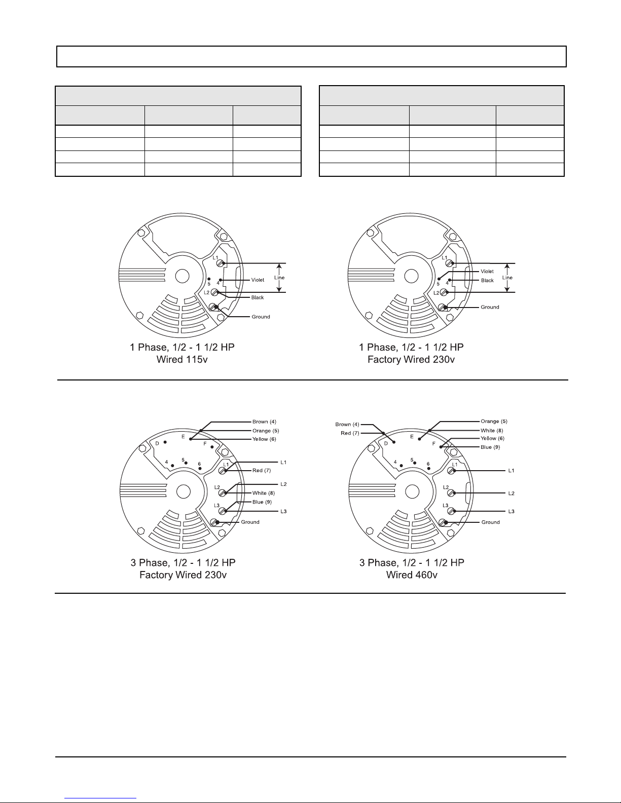
Note: See the decal displaying shaft rotation arrow on motor.
- 8 -
Bluffton Electric 1 Phase ODP Motor
Stock Number See Figure HP
1103017429 6 1/2
1103017430 6 3/4
1103017431 6 1
1103017432 6 1 1/2
Bluffton Electric 3 Phase ODP Motor
Stock Number See Figure HP
1303013103 7 1/2
1303023103 7 3/4
1303033103 7 1
1303043103 7 1 1/2
Figure 6
Bluffton Motors Connection Diagrams
Bluffton Motors Connection Diagrams
Figure 7
If the supply voltage is 460 volts, refer to the motor wiring diagram show in (Figure 7) to properly rewire the motor.
Motor shaft rotation - 3 phase motors
1. Turn the power off.
2. Remove the circular end cap located on the back of the motor. This will expose the motor shaft.
3. Momentarily start pump. If the connection is correct, the shaft will rotate clockwise. If not reverse any two
incoming lines (Power Leads).
Motor shaft rotation - 1 phase motors
1. To reverse rotation, interchange orange and red wires.
Page 9
- 9 -
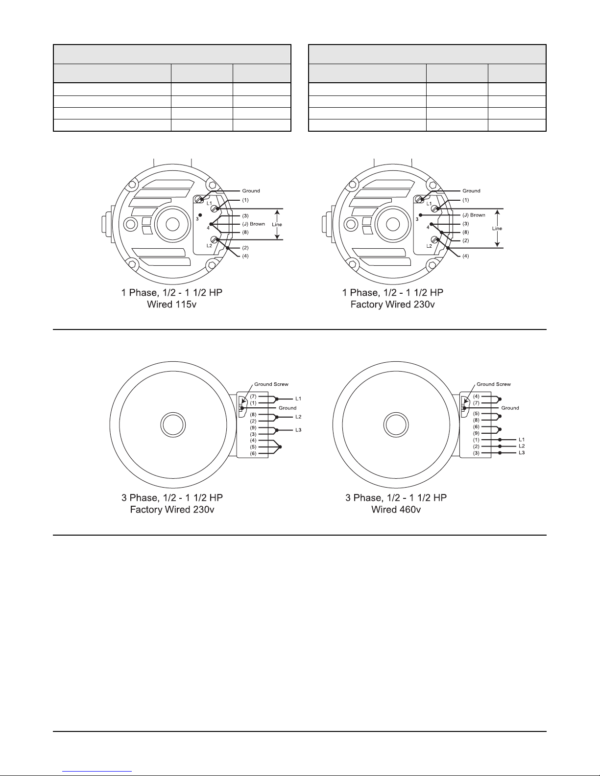
Figure 8
Baldor Motors Connection Diagrams
Baldor Motors Connection Diagrams
Figure 9
Baldor 3 Phase ODP Motor
Catalog Number See Figure HP
JM3107 9 1/2
JM3111 9 3/4
JM3115 9 1
JM3120 9 1 1/2
Baldor 1 Phase ODP Motor
Catalog Number See Figure HP
JL1303A 8 1/2
JL1306A 8 3/4
JL1309A 8 1
JL1313A 8 1 1/2
If the supply voltage is 460 volts, refer to the motor wiring connections shown in (Figure 9) to properly rewire
the motor.
Page 10

- 10 -
Shaft Rotation - To check for a free turning pump turn the power off and rotate the motor shaft. This can be
done by removing the motor end cap located on the back of the motor. Rotate the motor shaft in a clockwise
direction. Do not start the pump if the motor shaft cannot be turned.
Shaft Rotation (3 Phase Motors) - After the proceeding instructions have been completed, turn the motor on
for 1 second. If the connection is correct, the motor shaft will rotate clockwise when viewed from the end oppo-
site the motor shaft extension. If the rotation is not correct, reverse any two leads to the starter. The rotation will
now be correct.
Valves - The suction inlet valve should be fully open and the discharge valve should be partially open. This will
allow the pump to develop back pressure when it is started.
Priming - The pump will automatically fill with water when the pump is connected to a city main, hydrant or
water tank. To relieve the air trapped inside the pump, allow the water supply to run a minimum of 1 minute
before starting the pump. Then, turn the motor on and off several times to free the air trapped inside the pump.
Repeat this priming sequence several times to be sure all the air has been removed from the pump. Start and
run the pump for 1 minute. The pump should be pumping water and rapidly build pressure. If not repeat the
priming procedure.
Start-Up Procedures
Warning: The pressure gauge installed in the inlet line should never read less than 2 PSI. This insures
that an ample supply of water is flowing into the pump.
Starting - When the pump is up to operating speed, open the discharge valve to obtain the desired capacity or
pressure. Do not allow the pump to run with the discharge valve closed because the liquid in the pump can get
extremely hot.
Warning: The discharge pressure should never be allowed to exceed 85 PSI, otherwise, leakage between
the motor bracket and pump casing will occur.
Final Inspection - Once the proceeding instructions have been completed the pump can be started. During the
first few hours of operation, inspect the pump, piping and auxiliary equipment used in conjunction with the pump.
Check for leaks, vibration or noises.
If a problem arises, consult a Webtrol representative or call Webtrol at (314) 631-9200 for assistance.
Maintenance
The pump does not require special maintenance. If the pump is not going to be used for a long period, the pump
should be drained of water and flushed with clean water. Where the pump is exposed to freezing temperatures,
it should always be left drained when not in use.
Page 11

- 11 -
Notes:
Page 12

Motor Fails To Start Or Run At Full Speed
Possible Cause Of Trouble Corrective Action
Start capacitor failed - 1 phase motor (motor hums) Replace start capacitor
Power Loss Replace bad fuse or reset circuit breaker (check for correct fuse/breaker size)
Incorrect voltage - voltage must be within +
10% of motor rated voltage. 1. Check incoming voltage, contact power company
Example: Rated voltage 230 volts Range: 207 - 253 volts 2. Verify that the voltage of the motor matches the power supply voltage
3. Check wire size from main switch to motor.
Defective wire or connections Replace defective wires, tighten and clean connections.
Grounded motor Have motor rewound with new winding or replace motor.
Wired for incorrect voltage Check motor wiring diagram for proper voltage
Pump Leaks
Possible Cause Of Trouble Corrective Action
Worn mechanical seal due to abrasive liquid/corrosion 1. Replace seal with materials compatible with liquid pumped.
2. Install filter on inlet line.
Lack of water - carbon seal on mechanical seal face overheats and cracks or 1. Replace seal
wears rapidly 2. Verify inlet pressure, minimum pressure on inlet gauge is 2 PSIG
Inlet pressure to high 1. Discharge pressure not to exceed 85 PSI
2. Reduce inlet pressure
Misalignment of mechanical seal Check for a bent motor shaft
Worn or pinched O-ring seal Replace O-ring seal
System Trouble Shooting
Pump Operates, But Delivers Little Or No Water
Possible Cause Of Trouble Corrective Action
Incorrect rotation on 3 phase motor Interchange any two incoming power leads to the motor.
Low line voltage (See motor trouble shooting section above)
Air Locked Pump Fill pump & inlet pipe with water - jog motor on and off several times. Refill
with water. Repeat procedure several times to remove all air
Worn or plugged impeller 1. Replace impeller
2. Clean clogged impeller, install filter on Inlet
Inadequate inlet pressure Minimum pressure on the inlet side of pump is 2 PSIG
Diameter of suction/discharge pipe is to small 1. Size of inlet pipe should be at least equal to the threaded inlet size in the
pipe inlet housing
2. Calculate friction losses for the discharge pipe. Replace undersized piping.
For assistance call Webtrol (314) 631-9200
Broken Shaft If motor shaft is broken replace motor
Wired for incorrect voltage Check motor wiring diagram for proper voltage
Excessive Noise While Pump Is Operating
Possible Cause Of Trouble Corrective Action
Cavitation (noise like gravel in pump) 1. Increase size of inlet line
2. Reduce flow rate - GPM
3. Too viscous (liquid is too thick) maximum viscosity is 80 centipoise (CPS)
Pump not secured to firm foundation Bolt down to secure and rigid base
Noisy motor 1. Ensure that motor fan is clear
2. Remove motor from pump. If noise persists check for smooth bearing
operation. Replace bad bearings/or motor
Wired for incorrect voltage Check motor wiring diagram for proper voltage
Thank You For Purchasing A PC Series Pump
We at Webtrol are constantly working on new products to make your job easier, while making your systems
more efficient, reliable and affordable.
Your opinion means a lot to us, so please let us know what you think about our PC Series Pump.
Weber Industries, Inc. / Manufacturers of Webtrol Products
8417 New Hampshire Ave. / St. Louis, MO 63123
 Loading...