

Page 1

Installation Guide with
HyperTerminal Configuration
WT5800 Locator
WebTech Wireless Inc.
Version 0.4
September 2006
Page 2

© Copyright 2006 WebTech Wireless Inc. All rights reserved.
215-4299 Canada Way, Burnaby, BC V5G 1H3 Canada
email: [email protected]
Document #: 01100-668
Version: 0.4
Status:
Page 3

Contents
Module 1
Safety Hazards & Installation Requirements................................................... 1-1
Module 2
Configuration of the
Wireless Local Area Network (WLAN).............................................................. 2-4
Module 3
Locator Antenna Installation............................................................................. 3-5
Contact Information................................................................................. 1-1
Safety Hazards........................................................................................ 1-1
Installation Requirements........................................................................ 1-2
Customer Supplied SSID and WEP Key................................................. 2-4
Customer DID NOT Supply SSID and WEP Key .................................... 2-4
Locator Mounting and Placement Guidelines ......................................... 3-5
Antenna Installation Dos and Don’ts ....................................................... 3-6
GPS Antenna Installation ........................................................................ 3-7
Covert GPS Antenna Installation ............................................................ 3-8
802.11g Antenna Installation................................................................... 3-9
Module 4
Electrical Safety & Wiring Guidelines .............................................................. 4-10
Electrical Safety ...................................................................................... 4-10
Electrical Wiring Guidelines .................................................................... 4-11
Module 5
WT5800 Locator Wiring & Telemetry Activation ............................................. 5-15
Power Harness Installation ..................................................................... 5-15
Power/Serial Cable Connections ............................................................ 5-16
Power/Serial Cable Wiring Diagram........................................................ 5-17
LED Definitions and Checkpoints............................................................ 5-18
Telemetry Activation and Installation Check ........................................... 5-19
WebTech Wireless Inc. i
Page 4

WT5800 Installation Guide
Appendix A
Terminology and Background .......................................................................... A-1
Appendix B
Set Up & Configure the
Locator With HyperTerminal ............................................................................. B-1
Appendix C
What are WIFI, WLAN and WAP? .......................................................... A-1
What is a HyperTerminal?....................................................................... A-2
Why Is the Locator Configured to the WAP (the Router)? ...................... A-2
What is a Service Set Identifier (SSID)? ................................................. A-2
What is Wired Equivalent Privacy (WEP)?.............................................. A-3
Set up and Open HyperTerminal ............................................................ B-1
Configuring the Locator(s) Using HyperTerminal .................................... B-4
Laptops with USB Ports - Purchase USB to Serial Converter Adapter... B-6
Locator Information Sheets .............................................................................. C-1
Appendix D
Regulatory Information...................................................................................... D-1
Statement of the Federal
Communications Commission (FCC)...................................................... D-1
Appendix E
WT5800 Wiring Diagram ................................................................................... E-1
ii WebTech Wireless Inc.
Page 5

Safety Hazards & Installation Requirements
Module 1
Safety Hazards & Installation Requirements
Contact Information
If there are any questions contact WebTech Wireless Technical Support
email: [email protected]
Phone: 604-419-8163 or 1-866-287-0135 option 3
If you have any comments or suggestions regarding this document please
send an email to:
Updated versions of this manual are available on the customer portal at
www.webtechwireless.com.
Safety Hazards
This section describes important safety guidelines to follow while
installing a Webtech Wireless Locator.
Also refer to Electrical Safety on page 4-10.
Do not install or operate a WebTech Locator in areas where explosive
Do not install a WebTech Locator in any vehicle powered by liquefied
Do not install a WebTech Locator near life support or other sensitive
During car and truck installations, it is recommended that vehicle tires
atmospheres may be present.
petroleum gas or governed by petrochemical regulations without
additional operational safety precautions being taken.
equipment that may be affected by radio transmissions. If required,
consult the equipment manufacturer for guidance.
are blocked to prevent roll back.
Periodically throughout installation, the emergency brake will be off
and the engine running, during which time the vehicle may move
unexpectedly.
WebTech Wireless Inc. 1-1
Page 6
WT5800 Installation Guide
Installation Requirements
Equipment Included
Note A Wireless Local Area Network (WLAN) is required for the operation of
the WT5800 Locator. Refer to Configuration of the Wireless Local Area
Network (WLAN) on page 2-4.
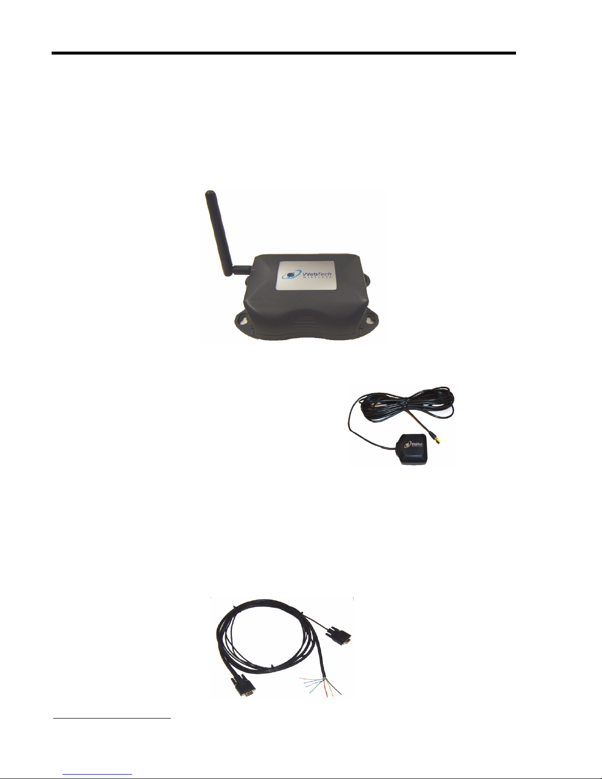
Figure 1-1 WT5800 Locator with an 802.11g antenna
Figure 1-2 GPS antenna and cable
The Locator is shipped with:
Two antennas: one 802.11g stubby and one GPS magnetic-mount
(as shown above).
The 802.11g stubby antenna is attached to the Locator and used in
both typical and covert installations.
An installation guide
A Locator information sheet (See Appendix C for an example)
A power/serial data cable
1-2 WebTech Wireless Inc.
Page 7

Equipment and Tools Required
To perform diagnostics and confirm Locator operation, a laptop
computer with one RS232 serial port available (or USB to 9 pin serial
adapter), serial cable and HyperTerminal communication software
may be required.
Wiring Tools and Accessories
Wire stripping tools
Multi-meter
Solder iron (butane recommended if there is no power source)
Crimp tool
Flashlight
Heat-shrink tubing
Automotive grade wire (16-18 AWG)
Electrical tape
Rosin core solder
Automotive wire ring terminals
In line ATO fuse holder
Fuses
Cable ties
Cable tie mounts
Safety Hazards & Installation Requirements
Hardware Mounting Tools and Accessories
Drill
Screwdriver
Screws
Nuts, washers, as required
Silicone sealant
Torque seal
WebTech Wireless Inc. 1-3
Page 8

WT5800 Installation Guide
Module 2
Configuration of the
Wireless Local Area Network (WLAN)
The WT5800 Locator is designed to be used in a wireless environment.
This section outlines two options to configure the WT5800 WIFI network
SSID and encryption key.
Note Refer toTerminology and Background on page A-1 for help with WLAN
terminology.
Customer Supplied SSID and WEP Key
IF the customer supplied the WIFI network SSID and WEP encryption key
to WebTech Wireless at the point of sale
THEN the WT5800 is pre-programmed by WebTech Wireless with the
customer supplied SSID and WEP encryption key.
Go to Locator Antenna Installation on page 3-5.
Customer DID NOT Supply SSID and WEP Key
IF the customer DID NOT supply a SSID and WEP encryption key to
WebTech Wireless at the point of sale
THEN the WT5800 is pre-programmed with a default SSID and randomly
generated WEP encryption key.
The default SSID and WEP encryption key is listed in the Locator
Information Sheet (shipping/packing list), which is included with
the WT5800 shipment (see an example of the Locator Information
Sheets on page C-1).
Go to Configuring the Locator(s) Using HyperTerminal on page B-4.
Note When Locator WLAN configuration is complete, go to Locator Antenna
Installation on page 3-5
2-4 WebTech Wireless Inc.
Page 9

Module 3
Locator Antenna Installation
This section describes the requirements and steps involved to install the
GPS and GSM802.11g antennas.
Proper antenna location and cabling technique is
critical to optimal operation and performance of the
Locator. This includes both coverage and throughput
performance.
Locator Mounting and Placement Guidelines
Avoid heat, e.g. proximity to heaters or ducts, engine
exhausts, or direct sunlight.
Locator Antenna Installation
Allow access to the Locator connectors such that the
LED is visible (where this is not a covert installation).
Protect the mounted Locator from moisture.
Place the Locator where physical damage to the unit is minimized,
e.g. under the dashboard or in the trunk.
Use a clean mounting surface if using Velcro.
Mount and secure the Locator with screws and drill the holes.The
Locator comes with holes in the flanges to enable mounting.
If the installation is covert go to Covert GPS Antenna Installation on
page 3-8.
WebTech Wireless Inc. 3-5
Page 10

WT5800 Installation Guide
Antenna Installation Dos and Don’ts
DO
Use only the supplied (or WebTech approved) antennas designed
for the correct frequencies.
Mount GPS antennas with a maximum view to the sky.
Mount antennas outside and on the vehicle roof (where possible).
Mount antennas securely. With through-hole installations, confirm
the installation is water tight (use silicone sealant).
DON'T
Don't mount antennas in areas with limited space for a ground
plane. Ground planes should provide at least 6" (15cm) of metal in
all directions.
Don't mount antennas close to another antenna. Provide as much
distance between antennas as possible. This includes the
GSM802.11g and GPS.
Don't mount antennas where they are covered or blocked by
metal.
Don't mount antennas close to people. Antennas should be
mounted where vehicle occupants will be separated from the
radiating element by at least 8" inches (20 cm).
Don't mount antennas where they are close to electronic
management and control systems.
Don't mount GPS antennas where they will be on an angle. They
should be horizontal to see as much sky as possible.
Don't run the GPS antenna cable to the roof of a vehicle through
the door. The vehicle door will eventually sever the cable and lose
connection between the GPS and Locator.
Don't tightly kink or wrap excess cable. Be careful not to trap any
cables when refitting trims to the vehicle.
Don't over tighten the connection between the antenna and the
Locator. Ensure that the antenna is not loose. E.g. hand tighten
then use a wrench to tighten another 1/8 of a turn (approximately).
3-6 WebTech Wireless Inc.
Page 11
GPS Antenna Installation
If the installation is covert also go to Covert GPS Antenna Installation on
page 3-8.
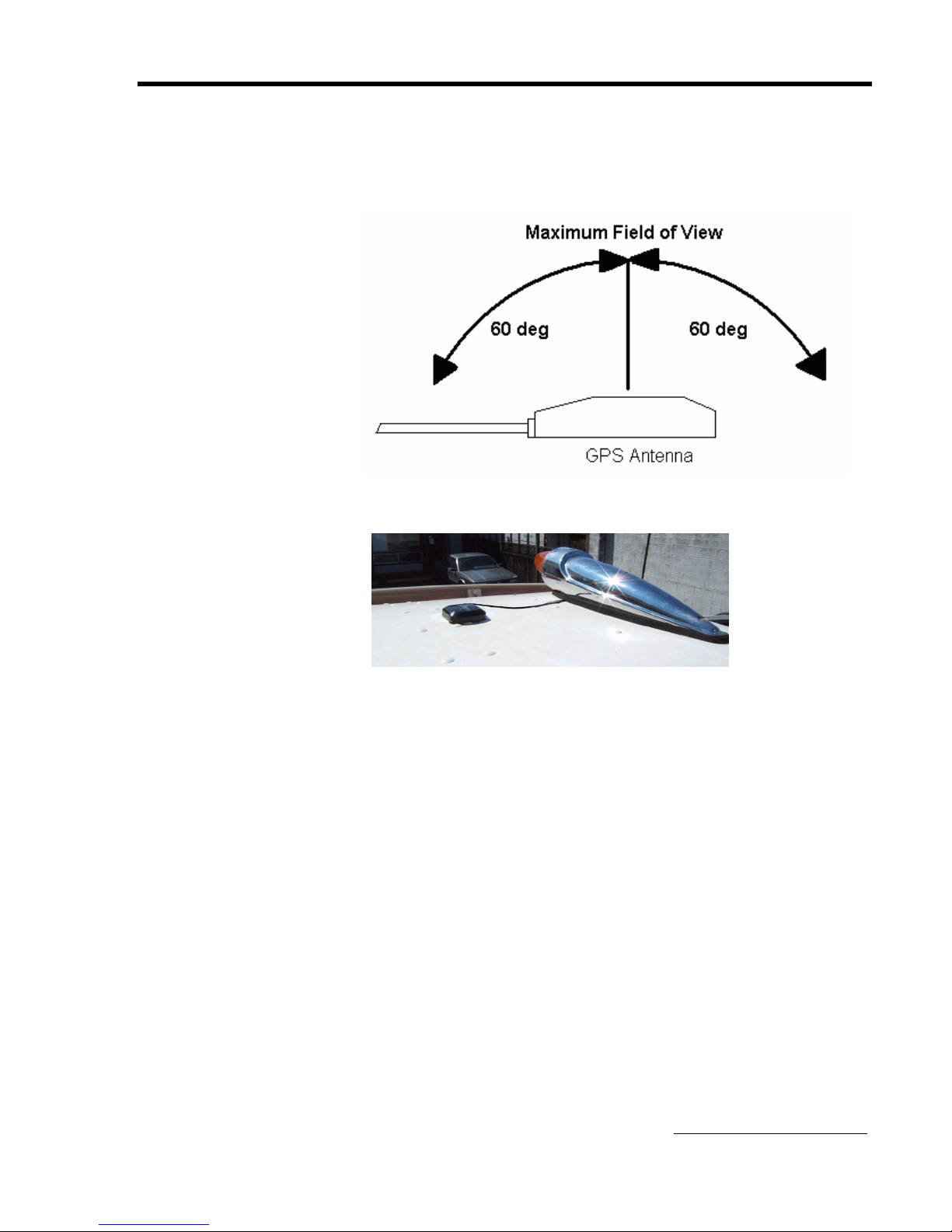
Important The GPS antenna must be facing up.
Locator Antenna Installation
Figure 3-1 GPS antenna mounted on a roof and facing up to the sky
Note Be careful when placing, moving or removing the magnetic-mount
antenna. Do not drag it across the metal surface as this will damage the
finish of the vehicle.
Installing the GPS Antenna
1. Determine the optimal location for the GPS antenna. Place and
mount the magnetic GPS antenna (square black antenna) on an area
of the vehicle where there is no obstruction of the sky, for example
On the vehicle roof or
Under a non-metallic dash in a vehicle with a sufficiently sloped
windshield.
2. Run the antenna cables to meet the Locator.
3. Confirm that the GPS has a fix (solid or flashing green LED) (refer to
LED Definitions and Checkpoints on page 4-16).
4. Secure the magnetic GPS antenna to the mounting area with
adhesive, e.g. silicone. Or consider installing a through-hole mount
antenna.
5. Secure cables using cable ties and mounts where applicable.
WebTech Wireless Inc. 3-7
Page 12

WT5800 Installation Guide
Covert GPS Antenna Installation
Important Test the GPS thoroughly under operational conditions.
Also go to 802.11g Antenna Installation on page 3-9.
The following must be considered with respect to the antenna's location.
These considerations apply to
All installations where it is essential the GPS antenna is hidden
from view.
Car and small truck installations where the Locator may be hidden
from view and installed under the dashboard or behind the stereo
system.
Larger trucks with sloped front windscreen or fiberglass rooftop
coated with a non-metallic paint.
Covert GPS Antenna Location
Ensure the view of the sky is as wide as possible.
Ensure the field of view is not obscured by any metallic object
(including front windscreens with heating, UV filters or metallic
tints).
Point the top of the antenna towards the field of view.
Enhance signal strength by mounting directly onto metal.
Optimal Covert GPS Antenna Mounting Locations
Under the front or rear window of the vehicle.
Under the dash lining.
Under a non-metallic parcel shelf.
In an instrument or light cluster.
3-8 WebTech Wireless Inc.
Page 13

802.11g Antenna Installation
Important Ensure the 802.11g stubby antenna is in the vertical position and the
connection to the Locator is secure.
The Locator is shipped with a stubby 802.11g antenna. This antenna
is adequate for most uses and required for all installations.
Use a WebTech approved external high-gain antenna if superior
coverage and throughput performance is required.
An optional dual-mode (802.11g/GPS) through-hole dome antenna is
available through WebTech Wireless Technical Support.
Locator Antenna Installation
Figure 3-2 Correct antenna orientation - vertical to sky
WebTech Wireless Inc. 3-9
Page 14

WT5800 Installation Guide
Module 4
Electrical Safety & Wiring Guidelines
Electrical Safety
Locate or confirm power sources prior to
disconnecting the vehicle battery.
Disconnect the vehicle battery prior to making any
electrical connections.
Important Safety Guidelines Include:
Consult the vehicle manufacturer guidelines regarding
disconnection of the vehicle battery or when making
supplementary electrical connections.
Before disconnecting a battery, understand the consequences to
that vehicle, e.g. radio codes need to be available and know the
reset procedure for airbag systems, ECU's etc.
Remove or cover any jewelry if working on live electrical systems.
Don't test electrical circuits using a test lamp. Use a high
impedance multi-meter with both voltage and resistance ranges.
Don't tamper with or disconnect the air bag or SRS electrical
harness.
4-10 WebTech Wireless Inc.
Page 15

Electrical Wiring Guidelines
Read these guidelines before preparing the harness.
Use appropriate pick-up points for power wiring
Important Don't splice into individual lines going to other electrical devices that
exhibit substantial momentary voltage drops.
For example, wires going to heating mirrors or a vehicle's
charging indicator are particularly susceptible.
If possible wire to a power bar or suitable common terminal connection
point.
Use a multi-meter to confirm +12 V DC or +24 V DC (9 to 30 Volts)
power. Do not use a test lamp.
Battery connection (red wire)
Ensure uninterrupted power to the Locator (supply voltage under
9Vdc) when the engine is being started.
Connect to a continuous +12V DC or +24V DC (9 to 30 Volts) supply.
Take from the secondary side of the main distribution fuse from the
vehicle battery. Do not share a fused supply to any other equipment.
Fuse the line at source to provide protection against shorting of the
wiring harness (the Locator is internally protected).
Electrical Safety & Wiring Guidelines
Negative Ground (Earth) connection (black wire)
Always connect directly to a dedicated earth point within the vehicle
electrical system.
Use a unique earth point.
When required, create a suitable earth point where no corrosion will
occur. A duplicate connection with other systems could cause a build
up in contact resistance.Supply voltage problems may occur and
result in erratic Locator operation.
Avoid earth points that also serve engine management ECU, ABS or
air bag systems etc.
Ignition connection (yellow wire)
Important To prevent incorrect operation, ensure the power is not interrupted for
more than 5 seconds when the engine is started (supply voltage under
9Vdc).
Connection to an ignition signal which goes positive +12V DC or
+24V DC (9 to 30 Volts) when the key is in the "run" position and is
removed or goes to ground when the key is in the "off" position.
WebTech Wireless Inc. 4-11
Page 16

WT5800 Installation Guide
Solder Connections
Important Ring connectors are ONLY acceptable for ground point and when
Ensure wiring is correct
connecting to power bars with screws. No other crimp connectors are
acceptable.
Wire should be fully inserted into the connector with insulation intact -
don't leave bare wire exposed
If wires are combined, ensure the connector can handle the resulting
gauge.
Be sure to crimp connectors properly with the correct sized crimp
tool. Confirm the physical connection is solid.
Solder the wire to the crimped connection.
Use toothed washers where bolting connectors to the vehicle. Make
sure the ground connection is solid and reliable.
It is critical that the ignition wire is connected to the
vehicle ignition wire and not to the battery.
Don't Use Quick Taps
Quick taps
Are not good for critical power supply connections.
Cut into the connected wire, reducing the life of the wire and
reducing its voltage and current handling capabilities.
Increase the risk of corrosion and crush-type wiring failures.
Note Vehicle vibrations will eventually separate a quick tapped wire from the
Locator, losing connection to the unit.
Don't leave cut wires exposed
Check for accidentally cut wires, which can damage vehicle wiring or
devices, and cause a fire.
Tape or heat-shrink all wire cuts so there is no risk of shorting or
corrosion.
If a splice is necessary, strip-away a small portion of the insulation,
solder the wires then protect by using electrical tape to re-insulate.
Don't leave free connector contacts or pins exposed. Tape or properly
terminate all connectors.
4-12 WebTech Wireless Inc.
Page 17

Route cables properly
Never put cabling where it will be stepped on, e.g. under rugs or
mats.
Never wire in areas that will retain moisture. E.g. insulation under the
carpet holds water and can be damp, making wiring connections
highly susceptible to corrosion.
Never put cable where a passenger or driver's feet rest on top of the
wires.
Never run the GPS antenna cable to the roof of a vehicle through the
door. The vehicle door will eventually sever the cable.
Where possible secure wiring in the wiring channel provided by the
vehicle manufacturer. Use split looms and grommets where
appropriate.
Tie wrap and tape cables (or cable tie mounts) to keep secure.
Electrical Safety & Wiring Guidelines
WebTech Wireless Inc. 4-13
Page 18

WT5800 Installation Guide
4-14 WebTech Wireless Inc.
Page 19

WT5800 Locator Wiring & Telemetry Activation
Module 5
WT5800 Locator Wiring & Telemetry Activation
Power Harness Installation
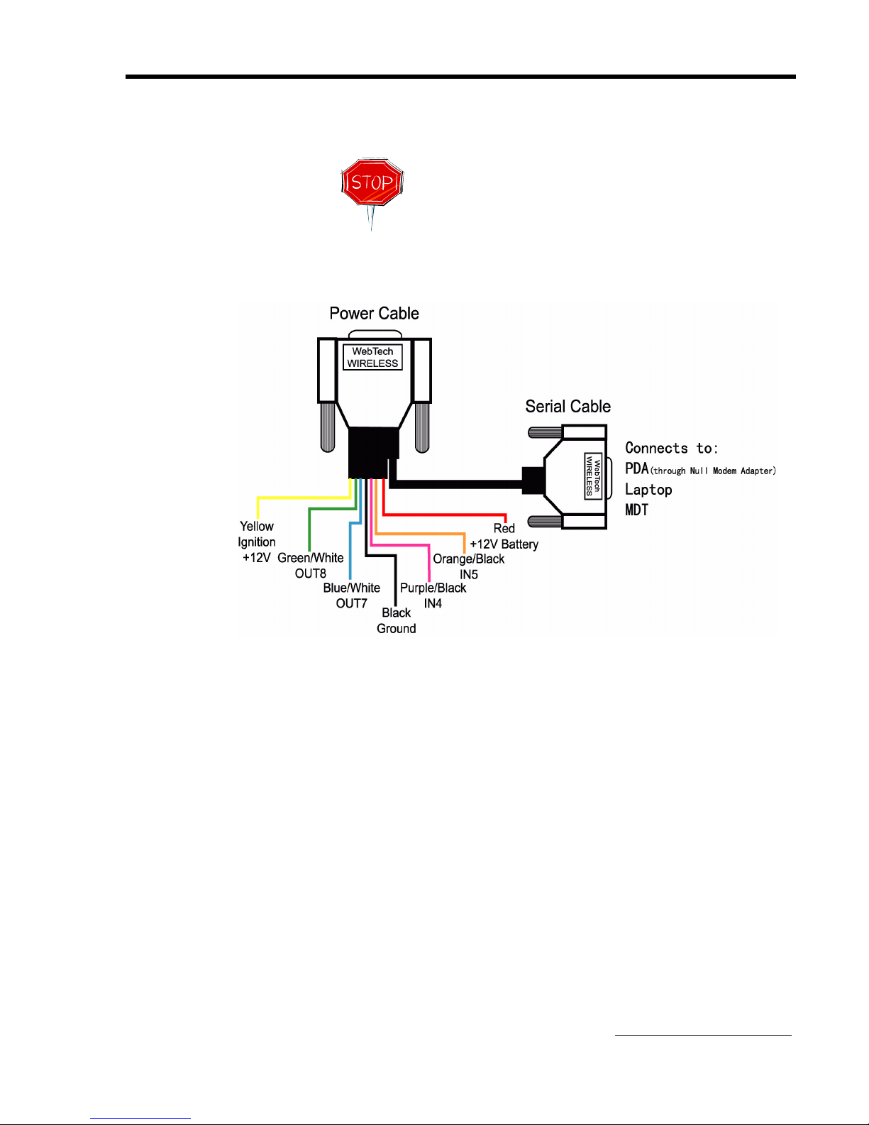
Also refer to Power/Serial Cable Wiring Diagram on page 5-17.
Correct vehicle wiring technique and hardware is
essential to proper Locator operation.
It is critical that the ignition wire is connected to the
vehicle ignition wire and not to the battery.
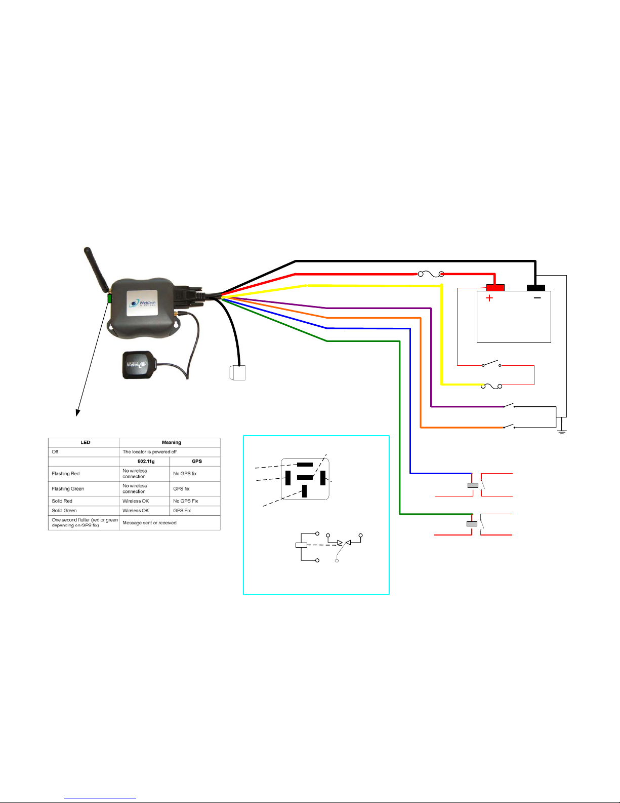
1. Connect red wire (battery) to +12V or +24V (9 to 30 Volts).
Ensure positive voltage is between 9 and 30 Volts.
2. Connect black wire (ground) to vehicle ground.
3. Connect yellow wire (ignition) to vehicle ignition.
WebTech Wireless Inc. 5-15
Page 20

WT5800 Installation Guide
Power/Serial Cable Connections
This section describes the power/serial data cable connections.
Table 5-1 WT5800 Power/Serial Data Cable Connections
Seq Color I/O Name General Description Install Description
1 Blue/White OUTPUT 7
2 Green/White OUTPUT 8
3 Purple/Black INPUT 4
4 Orange/Black INPUT 5
5 Yellow Ignition Ignition Mandatory
Power
6Red
7 Black GND Ground Mandatory
+12Vdc or
+24Vdc (9 to 30
Volts)
Note Use of the serial data connection is optional.
Ground pulse output
(200-milliamps)
Ground pulse output
(200-milliamps)
Input detecting ground
contact closure
(protected up to 30 V)
Input detecting ground
contact closure
(protected up to 30 V)
Power Supply Mandatory
Optional AUX
Optional AUX
Optional AUX
Optional AUX
General
Description
TX Data Optional Serial Cable
RX Data Optional Serial Cable
5-16 WebTech Wireless Inc.
Install Description
Page 21
WT5800 Locator Wiring & Telemetry Activation
Power/Serial Cable Wiring Diagram
Unused wires must be insulated to prevent shorts.
WebTech Wireless Inc. 5-17
Page 22
WT5800 Installation Guide
LED Definitions and Checkpoints
Table 5-2 LED Definitions
LED Meaning
Off The locator is powered off
802.11g GPS
Flashing Red
Flashing Green
Solid Red Wireless OK No GPS Fix
Solid Green Wireless OK GPS Fix
One second flutter (red or green
depending on GPS fix)
Table 5-3 LED Checkpoints
If the LED is flashing RED one
second off and one second on
If the LED is flashing GREEN
one second off and one
second on
No wireless
connection
No wireless
connection
Message sent or received
The Locator has neither a GPS fix nor a
wireless connection.
Ensure that the GPS antenna has a clear line
of sight to the sky and that the vehicle is in an
area with a WIFI 802.11 g access point.
The device has GPS activation but no
wireless connection.
Ensure that the wireless antenna is properly
attached to the device and that the vehicle is
in an area with a WIFI 802.11 g access point.
No GPS fix
GPS fix
If the LED has a solid RED
light
If the LED has a solid GREEN
light
5-18 WebTech Wireless Inc.
The device has wireless connection but no
GPS network visibility.
Ensure that the GPS antenna is properly
connected to the device and has a clear view
to the sky.
The Locator has both GPS and 802.11g
network coverage.
Page 23

WT5800 Locator Wiring & Telemetry Activation
Telemetry Activation and Installation Check
1. Contact Technical Support
During regular business hours, contact Technical Support by
phone 1-866-287-0135 option 3.
Outside of business hours, send an email to
2. Provide the following information to Technical Support
a. The Locator serial number
b. Unique vehicle identifier (e.g. vehicle name)
c. Telemetry information about the activated inputs and outputs
(where applicable)
Note A telemetry activation fee may apply.
WebTech Wireless Inc. 5-19
Page 24

WT5800 Installation Guide
5-20 WebTech Wireless Inc.
Page 25

Appendix A
Terminology and Background
This section provides an overview of WLAN terminology that will assist
with the configuration of a WebTech Wireless Locator to a WLAN. It is not
intended to provide users with in-depth instructions to set up a WLAN.
What are WIFI, WLAN and WAP?
WI FI is the name for a Wireless Local Area Network (WLAN). WIFI
communication technology is synonymous with the IEEE 802.11 family of
wireless networking standards, which includes the three established
standards 802.11b, 802.11a and 802.11g. The WT5800 Locator uses the
802.11g standard.
A Wireless Access Point (WAP) is a component of a WLAN. It is a device
that connects wireless communication devices to a broadband router
(Router).
Terminology and Background
Important The WLAN must be set up prior to configuring the Locator(s) and before
vehicle installation.
Note Follow the manufacturer's instructions to set up the WAP Router. An
internet connection is required for the Router setup and it needs the
DHCP server enabled, with default firewall settings recommended.
Note To maximize a WLAN signal range requires several placement
considerations, e.g. the number, thickness and location of walls, ceilings,
or other objects may limit the range of the signal. Typical ranges vary
depending on the types of materials and background RF (radio
frequency) noise. Refer to the Manufacturer's instructions for more
information.
WebTech Wireless Inc. A-1
Page 26

WT5800 Installation Guide
What is a HyperTerminal?
Why Is the Locator Configured to the WAP (the
Router)?
Note These instructions apply to a HyperTerminal operating in a Windows XP
environment.
HyperTerminal is a software communications program that is standard
with the installation of a Microsoft Windows operating system. It is a tool
used to connect other computers and devices together. The
HyperTerminal is also used for testing modems and other terminal
equipment, in this case, the WT5800 Locator.
The Locator collects information using GPS technology. This information
is stored on the Locator until it is transmitted to the Webtech Wireless
Quadrant server. The WLAN enables this transmission of data.
The Locator must identify the correct WAP device (the Router) to which
the data will be transmitted. The unique identifier (SSID) and the
corresponding encryption (WEP) enable the two devices to communicate
with each other. See Set up and Open HyperTerminal on page B-1 for
more information.
What is a Service Set Identifier (SSID)?
Each device in a wireless network MUST use the same
SSID or the wireless network will not function
properly.
The Service Set Identifier (SSID) is the unique name assigned to the
wireless network. The SSID in the Router has a factory default setting.
Important Hackers know wireless factory defaults.
Change the SSID default to a unique identifier and change it
periodically.
Disable SSID broadcast.
While setting up the Router, write down the new and unique SSID for use
during Locator configuration.
If the unique SSID is lost or forgotten, consult the Router manual
to find out how to recover or change it.
A-2 WebTech Wireless Inc.
Page 27

Terminology and Background
What is Wired Equivalent Privacy (WEP)?
Each device in a wireless network MUST use the same
WEP key or the wireless network will not function
properly.
Wired Equivalent Privacy (WEP) is a method of encrypting network data
transmitted on a wireless network. The WEP encryption key must be set
(and matched) in both the Router and in the Locator. This is done through
HyperTerminal (refer to Configuring the Locator(s) Using HyperTerminal
on page B-4).
The Locator uses two encryption types.
1. WEP 64-bit encryption requires an entry of exactly 10 hexadecimal
characters (the HEX key).
2. WEP 128-bit encryption requires an entry of exactly 26 hexadecimal
characters (the HEX key).
Valid HEX key characters are "0" to "9" and "A" to "F".
While setting up the Router, write down the new and unique WEP key for
use during Locator configuration.
If the unique WEP key is lost or forgotten, a new one must be set
up on the Router.
WebTech Wireless Inc. A-3
Page 28

WT5800 Installation Guide
Appendix B
Set Up & Configure the
Locator With HyperTerminal
This section applies to an infrastructure network installation and not adhoc data mode.
When a wireless network is set to infrastructure mode, the wireless
network is configured to communicate with a WLAN through a WAP.
Set up and Open HyperTerminal
Note If HyperTerminal is not set up continue with this Section.
If HyperTerminal has previously been set-up, go to Opening a
HyperTerminal (Previously) Set Up on page B-2.
The steps apply to a HyperTerminal operating in a Windows XP
environment.
The PC or laptop must have an available COM port.
If the laptop does not have a COM port, go to Laptops with USB Ports
- Purchase USB to Serial Converter Adapter on page B-6 for further
instructions.
Setting up HyperTerminal
1. Connect the DB9 female primary serial port into the computer's COM
port.
2. Open the HyperTerminal software. Go to Start >All Programs
>Accessories >Communications > HyperTerminal.
3. Click on the HyperTerminal icon to launch the software.
4. Enter the answers to the following questions
a. Select the country in which the WAP will operate from the pull
down list (e.g. Canada).
b. Enter any area code (e.g. 604).
B-1 WebTech Wireless Inc.
c. Enter a name for the new connection (e.g. WT5800 Locator
Tests).
d. Select an icon to be associated with the connection.
e. Enter any phone number (e.g. 555-5555)
Page 29
Set Up & Configure the Locator With HyperTerminal
5. Click OK.
6. Enter a name e.g. WTW or Test.
7. Click OK.
8. On Connect to Dialogue select the COM port to which the Locator is
attached from the Connect Using drop down list.
This will gray out the rest of the fields.
9. Click OK.
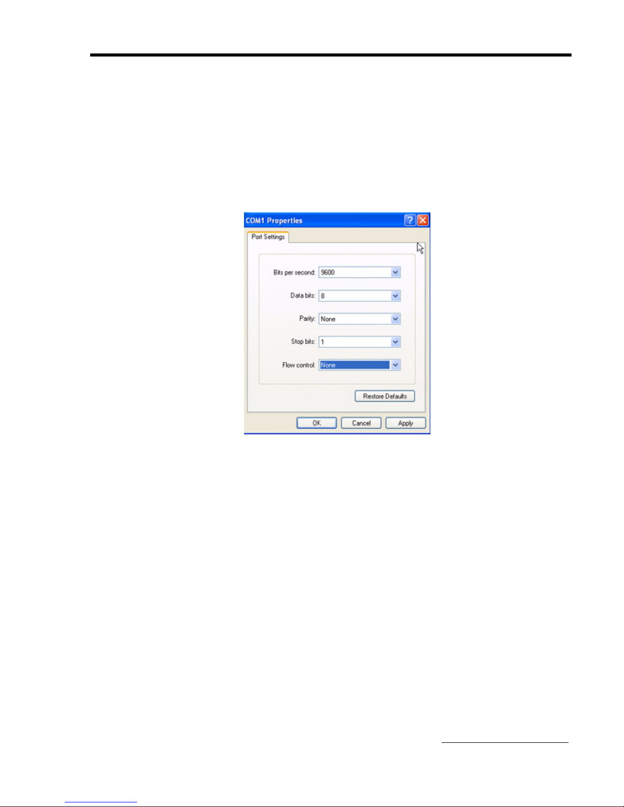
10. Configure the COM Port Settings as follows
a. Bits per Second: 9600
b. Data Bits: 8
c. Parity: None
d. Stop Bits: 1
e. Flow Control: None
11.Click Apply.
12.Click OK.
Opening a HyperTerminal (Previously) Set Up
Note The steps apply to a HyperTerminal operating in a Windows XP
environment.
The PC or laptop must have an available COM port.
If the laptop does not have a COM port, go to Laptops with USB Ports
- Purchase USB to Serial Converter Adapter on page B-6 for further
instructions.
1. Connect the DB9 female primary serial port into the computer's COM
port.
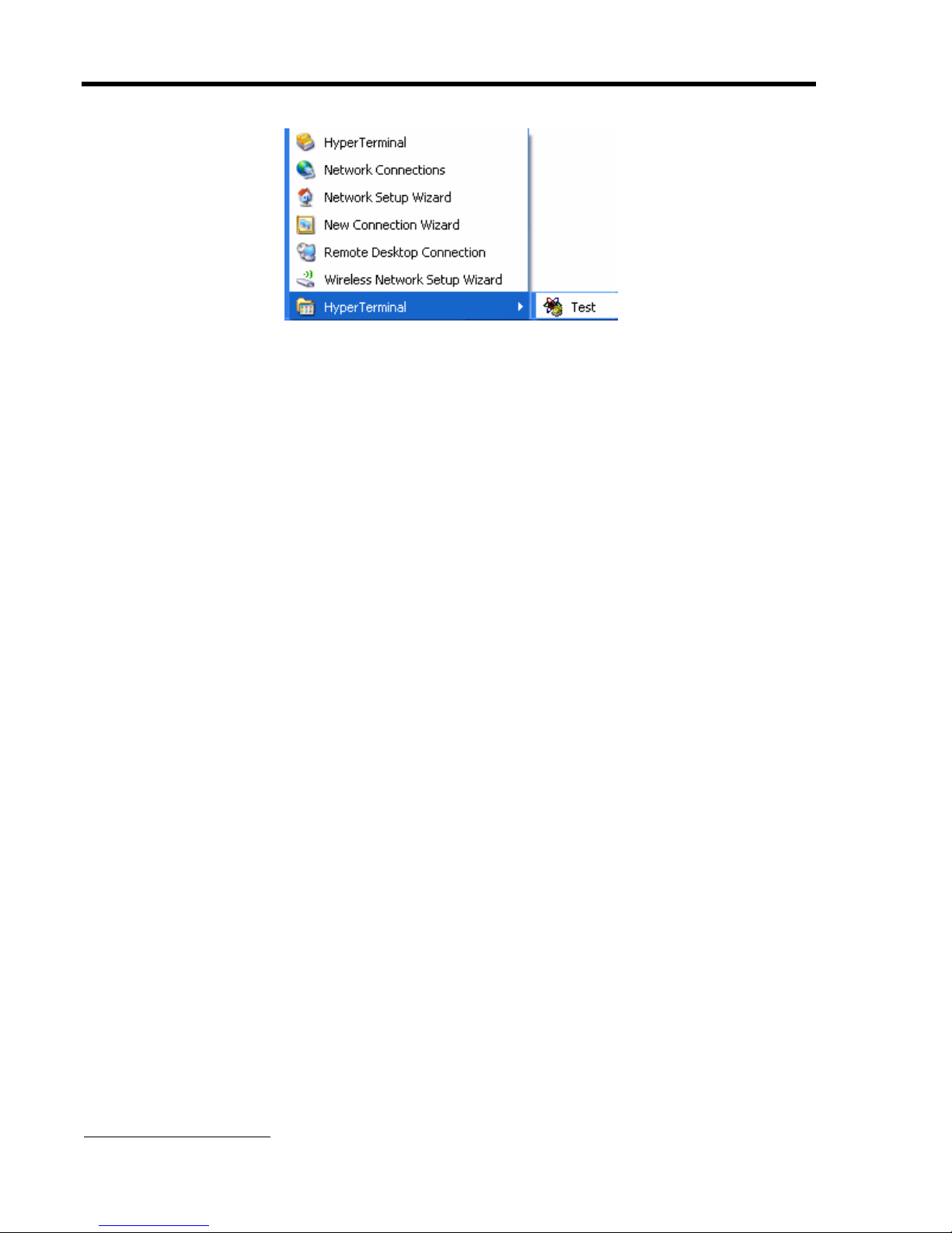
2. Open the HyperTerminal sub-menu: Start>All Programs
>Accessories> Communications>HyperTerminal Folder
WebTech Wireless Inc. B-2
Page 30
WT5800 Installation Guide
3. Click HyperTerminal>HyperTerminal icon (e.g.Test).
The HyperTerminal screen opens.
4. Continue with Configuring the Locator(s) Using HyperTerminal on
page B-4.
B-3 WebTech Wireless Inc.
Page 31

Set Up & Configure the Locator With HyperTerminal
Configuring the Locator(s) Using HyperTerminal
Important HyperTerminal configuration requires an independent power source to
power the Locator during configuration.
1. In the HyperTerminal screen, click the Call or Connect button .
Or use the pull down menu Call>Call.
2. Apply +12V DC or +24 V DC (9 to 30 Volts) power to red (power) and
yellow (ignition) wires.
3. Connect black wire (ground).
4. Press ENTER immediately and continuously to "wake up" the
connection and get the Locator out of the default "PPP" mode.
!CMD! appears in HyperTerminal screen.
Important Step 2 and 3 must be done within 5 seconds of each other and done
continuously for 15 seconds.
5. Press ENTER.
? appears to the left of the HyperTerminal screen.
6. Type gateway and a space.
7. Enter the unique SSID of the Router.
8. Type @
9. Enter the unique WEP key.
The WEP key is a 10 hexadecimal code created at the time of Router
installation. The full string will be similar to the following:
Note The WEP key is case sensitive.
gateway abcrouter@1A2B345678
10. Press ENTER.
11. Type config save next to the ?
12. Press ENTER.
The word Saved appears on screen. The configuration is saved.
13. Type restart.
The Locator is configured.
Disconnecting and Continuing Configuration and Testing
1. Disconnect the Locator.
It is ready for vehicle installation.
2. Connect another Locator.
3. Go to Step 1 of Configuring the Locator(s) Using HyperTerminal on
page B-4.
Complete Steps 1 to 15 until all Locators have been configured and
verified.
WebTech Wireless Inc. B-4
Page 32

WT5800 Installation Guide
4. Go to Locator Antenna Installation on page 3-5 and begin Locator
vehicle installation.
B-5 WebTech Wireless Inc.
Page 33

Set Up & Configure the Locator With HyperTerminal
Laptops with USB Ports - Purchase USB to Serial
Converter Adapter
Most laptop models come with only USB ports (i.e. no serial port). The
HyperTerminal and Locator configuration requires a serial to modem
connection (i.e. a COM port).
Purchase a USB to serial converter adapter cable, which will create a
serial to modem connection (e.g. a COM port).
Note The COM port made available after installation of the USB to serial cable
driver is usually a higher number COM port, e.g. COM4.
Once the adapter is installed on the laptop, continue with Setting up
HyperTerminal on page B-1.
WebTech Wireless Inc. B-6
Page 34
WT5800 Installation Guide
Appendix C
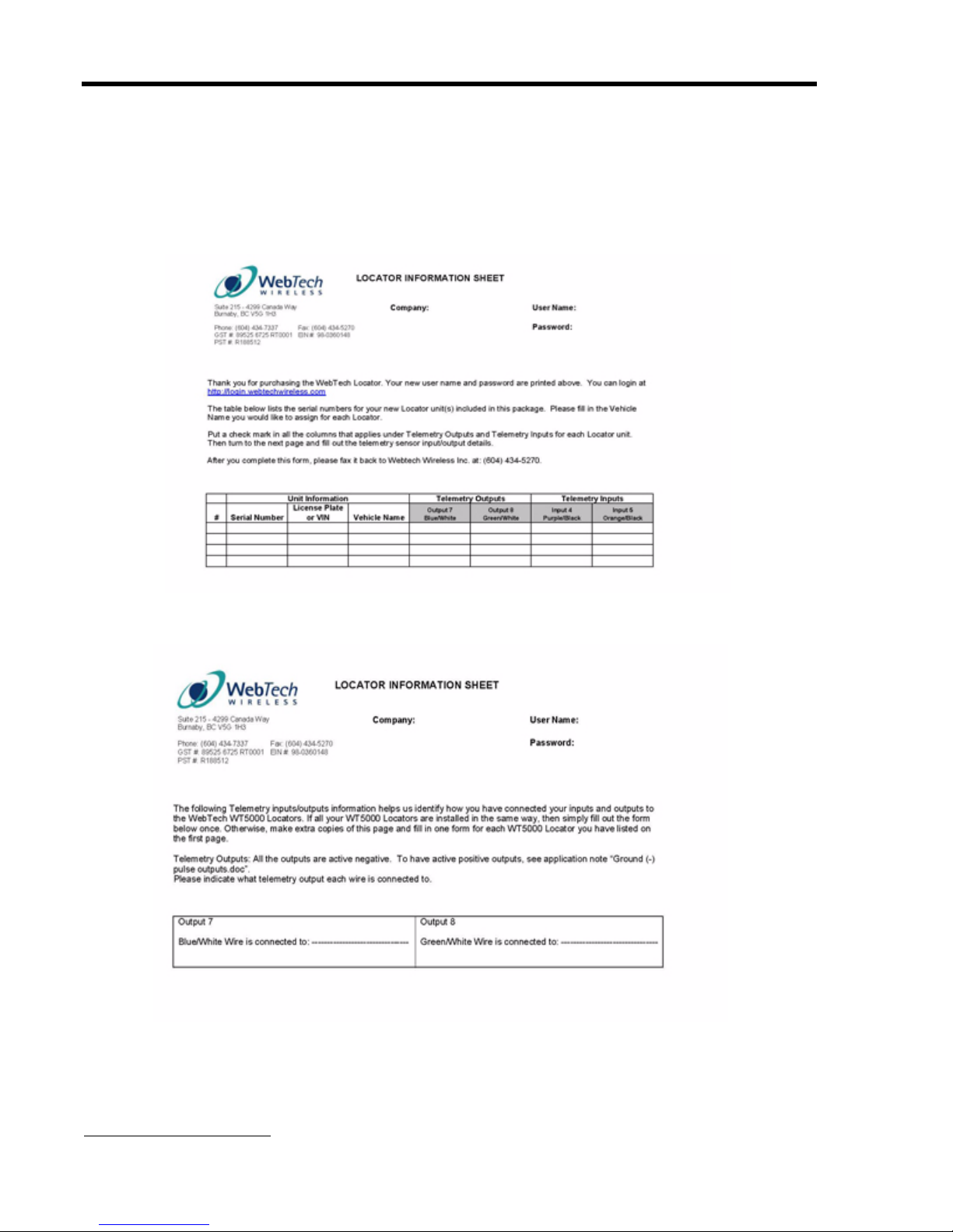
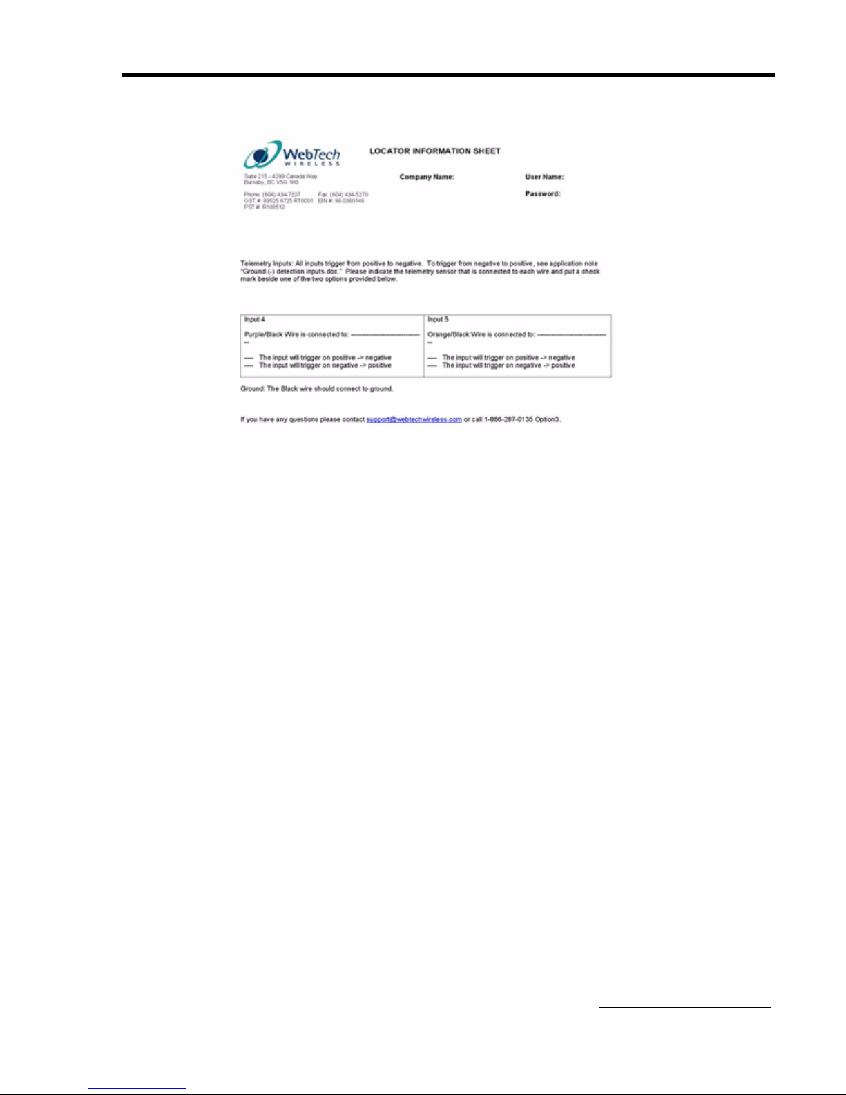
Locator Information Sheets
C-1 WebTech Wireless Inc.
Page 35
Locator Information Sheets
WebTech Wireless Inc. C-2
Page 36

WT5800 Installation Guide
C-3 WebTech Wireless Inc.
Page 37

Appendix D
Regulatory Information
Statement of the Federal
Communications Commission (FCC)
15.21
You are cautioned that changes or modifications not expressly approved
by the part responsible for compliance could void the user's authority to
operate the equipment.
15.105(b)
This equipment has been tested and found to comply with the limits for a
Class B digital device, pursuant to part 15 of the FCC rules. These limits
are designed to provide reasonable protection against harmful
interference in a residential installation. This equipment generates, uses
and can radiate radio frequency energy and, if not installed and used in
accordance with the instructions, may cause harmful interference to radio
communications. However, there is no guarantee that interference will not
occur in a particular installation. If this equipment does cause harmful
interference to radio or television reception, which can be determined by
turning the equipment off and on, the user is encouraged to try to correct
the interference by one or more of the following measures:
Regulatory Information
Reorient or relocate the receiving antenna.
Increase the separation between the equipment and receiver.
Connect the equipment into an outlet on a circuit different from that to
which the receiver is connected.
Consult the dealer or an experienced radio/TV technician for help.
Operation is subject to the following two conditions:
1. This device may not cause interference and
2. This device must accept any interference, including interference that
may cause undesired operation of the device.
FCC RF Radiation Exposure Statement
This Transmitter must not be co-located or operating in conjunction with
any other antenna or transmitter.
This equipment complies with FCC RF radiation exposure limits set forth
for an uncontrolled environment. This equipment should be installed and
operated with a minimum distance of 20 centimeters between the radiator
and your body.
WebTech Wireless Inc. D-1
Page 38

WT5800 Installation Guide
D-2 WebTech Wireless Inc.
Page 39
Power/data cable
LED
Primary Serial
Data RS232
Interface
Female DB9
connector
Connects to MDT,
laptop, PDA etc
Good vehicle ground (black)
Battery (+) (red)
Ignition (yellow)
12 Vdc or 24 Vdc
BATTERY
Inline fuse 5A
Inline fuse 3A
Vehicle ignition switch
Input 4 (purple/black)
Input 5 (orange/black)
Input 4 (telemetry)
Input 5 (telemetry)
Output 7 (blue/white)
Output 8 (green/white)
>>
>>
<<
In Contact 1
Out Contact 1
Battery (+)
<< >>
>>
In Contact 2
Out Contact 2
Battery (+)
Automotive
Relay (RE1)
Automotive
Relay (RE2)
30
85
86
87
87A
Relay Pin Front View (pin ends)
N/O
N/C
Coil
Common
Coil
Relay Pin Side View
86
30
85
87
87A
Standard Automotive
Relay Pin Configuration
LED Status
WT5800 Locator Wiring
Including Optional Telemetry Wiring
GPS
SW2
SW3
SW1
Document # 01100-0806
August 2006
 Loading...