

Page 1
NEED HELP?
877.786.1105
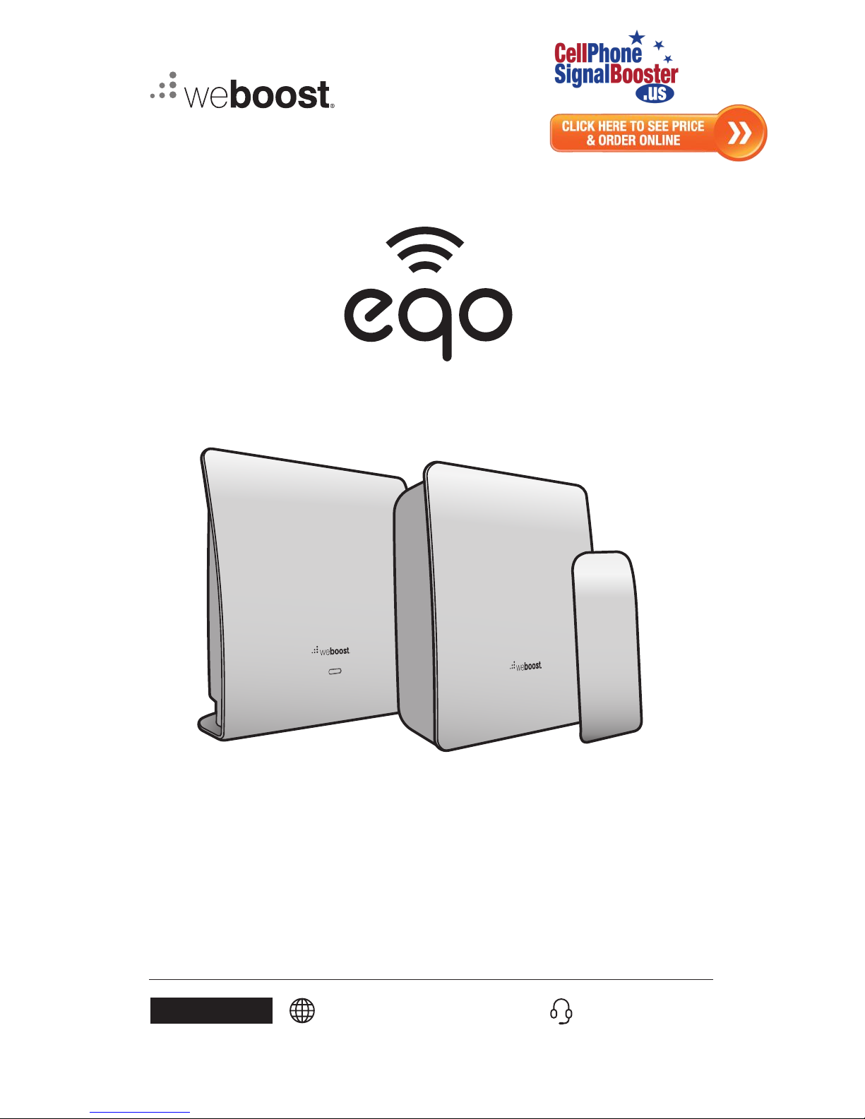
User Manual
Cell Phone Signal Booster
Cell Phone Signal Booster
Page 2
______
Index
Package Contents 1
Accurately measuring cell signal strength 2
STEP 1: Place Booster In Strong Signal Location 3
STEP 2: Connect the 6’ Cable to the Booster Unit 4
STEP 3: Outside Antenna 4
STEP 4: Connect the 25’ Cable to Booster Unit 5
STEP 5: Place Antenna In Weak Signal Location 6
STEP 6: Connect the Booster to Power 7
Troubleshooting 8
Specifications 10
Safety Guidelines 11
Warranty 12
Page 3
CELL PHONE SIGNAL BOOSTER
1
________
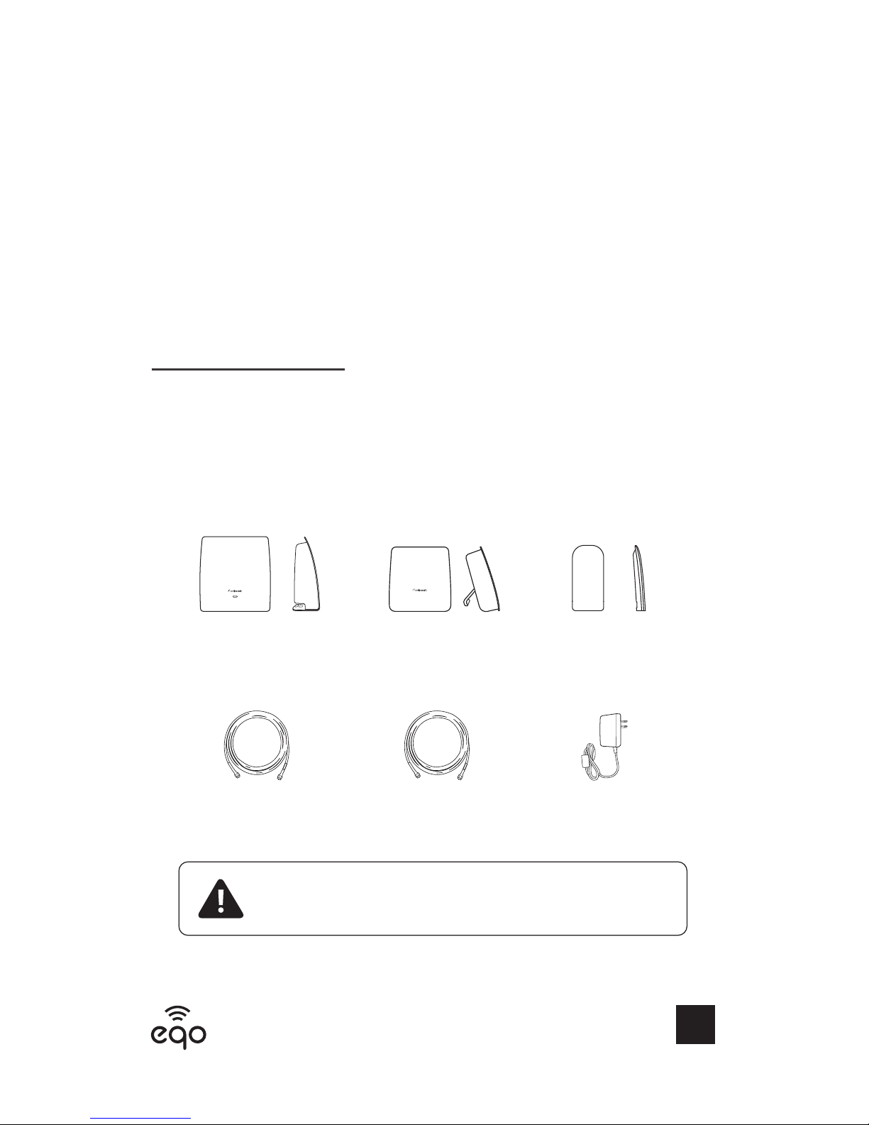
Package
Contents
eqo
Booster
eqo
Inside
Antenna
eqo
Outside
Antenna
25’ Coax
Cable
6’ Coax
Cable
Power
Supply
This device may be operated ONLY in a fixed location for in-building
use. The signal booster unit is designed for use in an indoor,
temperature controlled environment ( < 100 degrees Fahrenheit)
Page 4
2
CELL PHONE SIGNAL BOOSTER
Dial *3001#12345#* then press Call.
Hold down power button until you see “Slide to Power O”
then release the power button.
Hold the Home button until your main screen appears.
If you want to check 3G/1x but your iPhone is picking up 4G/
LTE signal, go to Settings>Cellular>Cellular Data Options>Enable LTE>Select O
After you system is set up, you can go back to the dots signal
ready by once again dialing *3001#12345#* then pressing call.
When the menu comes back up, tap “phone” in the top left
corner of your phone
Settings > About Phone > Status or Network > Signal Strength
or Network Type and Strength (exact options/wording
depends on phone model).
______
Accurately measuring cell
signal strength
All Other Phones & Alternate Methods
• https://www.weboost.com/test-mode-instructions/
All Phones:
• Keep track of the network (3G or 4G) phone is connected to.
• Any signal readings you take are valid for that phone’s carrier. To get readings
from other carriers, you’ll need phones from each carrier.
Find The dBm Reading On Your Phone
iPhone®
Android™
NEED HELP?
iPhone is aregistered trademark of Apple Inc. Android is a trademark of Google Inc.
877.786.1105
Cell Phone Signal Booster
Page 5
CELL PHONE SIGNAL BOOSTER
3
______
Step 1: Place Booster In
Strong Signal Location On or
Near Window Sill
IMPORTANT: This is the most critical step of the installation process because it
will determine the overall performance of the ooster system. Do not connect the
Booster to power until STEP 4.
Having an accurate measurement of signal strength in decibels (dBm) is crucial when
installing your system. Decibels accurately measure the signal strength you are
receiving.
SIGNAL STRENGTH EXCELLENT GOOD FAIR POOR DEAD ZONE
3G/1x
(typically voice)
-70dBm -71 to -85dBm -86 to -100dBm -101 to -109dBm -110dBm
4G/LTE
(typically data)
-90dBm -91 to -105dBm -106 to -110dBm -111 to -119dBm -120dBm
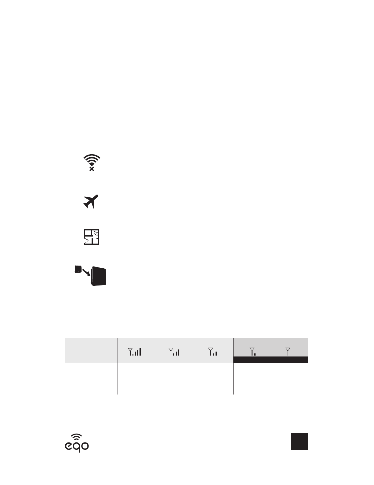
Turn o your cell phone’s WiFi to ensure you are checking the
cellular connection. The dBm reading will be refreshed every
30-60 seconds.
Want faster results? Once you have a reading, turn on airplane
mode. Wait 15 seconds. Turn o airplane mode. The signal
strength reading is refreshed.
Walk around your home/oce taking signal strength readings
until you find the window that has the best reception.
Place your Booster in the area with the strongest cell phone
signal. The LED light, and weBoost logo should be facing into
the room. Note this will need to connect to the Inside Antenna
(Step 5) with the 25’ Cable.
-95
dBm
-90 dBm
-100 dBm
*May Need External Antenna
If you're not able to get a strong cell signal, try using an app like Open Signal to find
the side of your house closest to a cell phone tower and install the booster on that
side of the house.
Booster
Antenna
Page 6
4
CELL PHONE SIGNAL BOOSTER
______
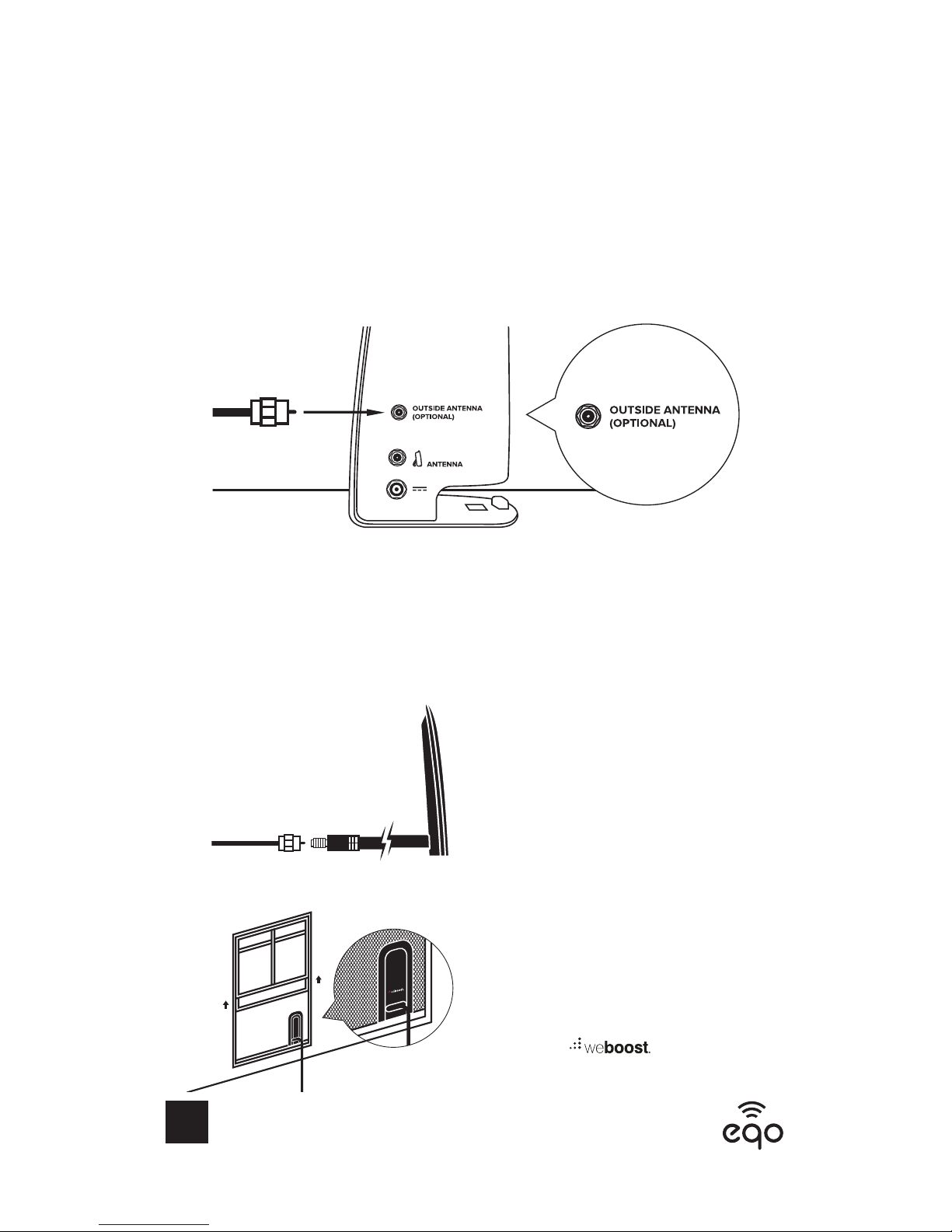
Step 2: Connect the 6’ Cable
to the Booster Unit Port
Labeled “Outside Antenna”
______
Step 3: Outside Antenna
2
Open window, place Outside Antenna
between window and window screen
with the logo facing inside
1
Connect the Outside Antenna to the
6’ Cable (from Step 2)
6’ Cable
6’ Cable
Outside
Antenna
Page 7
CELL PHONE SIGNAL BOOSTER
5
______
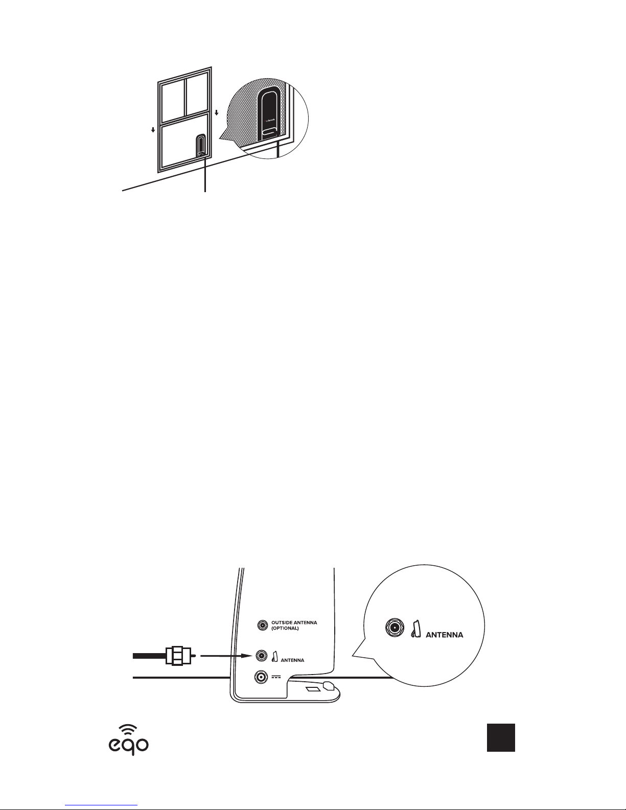
Step 4: Connect 25’ Cable to
Booster Unit Port Labeled
“Antenna”
3
Close window (Don’t worry, the flat
cable will be okay)
•If your window does not open, skip steps 2 & 3.
•If this is the case, it is important to have the Booster (Step 1) in the window
sill with the weBoost logo facing inside the house.
•If you don’t have a screen to hold the outside antenna, use the included
double-sided adhesive to stick the antenna against the window.
•For areas in full basements, place outside antenna as high on the window
as possible.
PLEASE NOTE: If your window does not have Low-E glass, it is best to use the booster
without the outside antenna. Most new windows use Low-E glass. If you’re unsure, test
results both with and without using the outside antenna. Just remember to disconnect
the outside antenna cable from the booster if you’re not using the outside antenna.
25’ Cable
Page 8
6
CELL PHONE SIGNAL BOOSTER
15’ to 25’
15’ to 25’
15’ to 25’
15’ to 25’
15’ to 25’
15’ to 25’
Antenna LocationAntenna Location
Antenna Location
Antenna Location
Antenna Location
Booster
Booster
Antenna
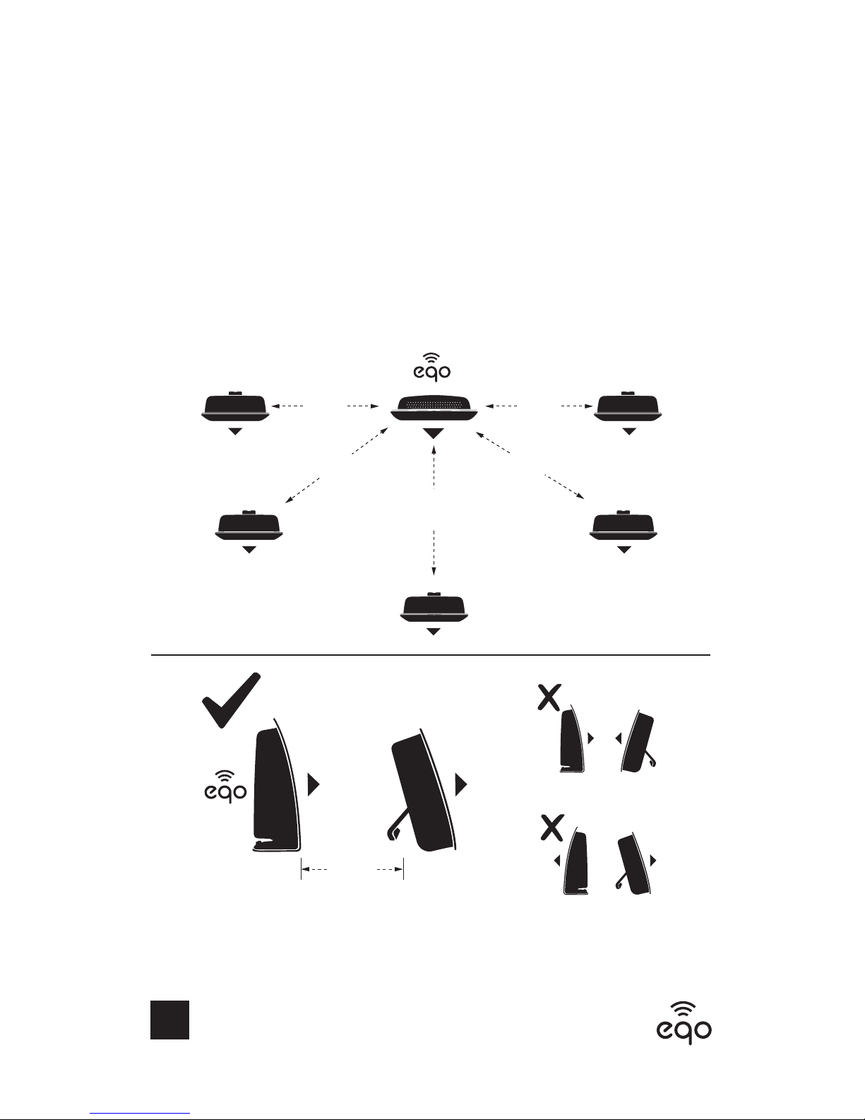
IMPORTANT: The further apart the ntenna is located from the Booster the better
your coverage will be. To determine the best location for your Booster, note the dBm
reading in a variety of locations.
______
Step 5: Place Inside Antenna
In Weak Signal Location and
Connect to 25’ Cable
The eqo Booster and ntenna should face the
same direction 15 to 25 feet separation distance.
Never face to face
Never back to back
NOTE: You can mount the antenna on a wall by removing the soft cover.
Page 9
CELL PHONE SIGNAL BOOSTER
7
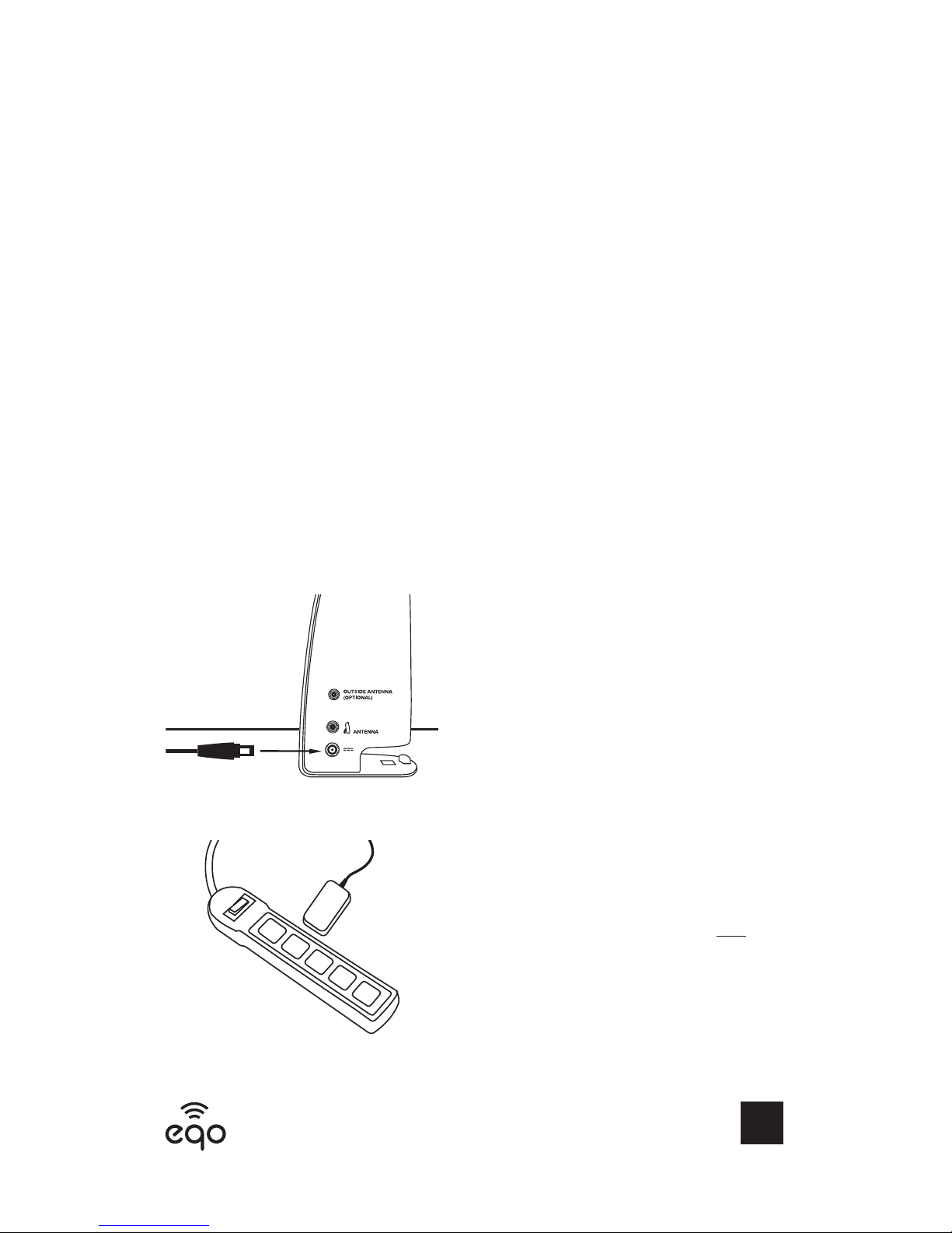
2
Plug the Booster in. The light may
change colors for the first 15 seconds.
Check your coverage area. efer
to TROUBLESHOOTING section if
needed.
______
Step 6: Connect The Booster
to Power
Power Cable
1
Connect the Power Supply on the side
of the Booster.
Surge Protector
Power Strip
Page 10

8
CELL PHONE SIGNAL BOOSTER
______
Troubleshooting
Fixing Red Light Issues
This section is only applicable if the ooster light is red and you are
not experiencing the desired signal boost. After each step, always un-plug and
re-plug the power supply so the ooster can update the signal reading.
1 Unplug the ooster’s power supply from the power strip.
2 Verify the ooster faces in the same direction as the ntenna.
3 Make sure all coax connections are finger-tight.
4 Move the ooster and ntenna further from each other.
5 Plug power supply back into power strip.
6 Monitor the indicator lights on your ooster. If, after 15 seconds of ‘power on’
a red light appears, repeat above ‘Troubleshooting’ steps 1-5. Note: Parallel
separation of the ooster and ntenna typically requires a shorter separation
distance than perpendicular separation. If possible, try placing the ntenna
directly in front of the location of the ooster. A combination of vertical and
horizontal separation distance also works to increase system gain.
7 If you are having any difficulties while testing or installing your ooster, contact
our weBoost Customer Support team for assistance at
https://cellphonesignalbooster.us/contact-us
or visit877.786.1105
Fixing Orange Lights Issues
This section is only applicable if the ooster light is orange and you are
not experiencing the desired signal boost. Orange light indicates there is a cell
tower close by.
1 Unplug the Booster’s power supply from the power strip.
2 Redirect the ooster to point in another direction. Typically, we recommend
turning the ooster 5-10 degrees at a time.
3 Plug power supply back into power strip.
4 Monitor the indicator lights on your ooster. If, after 15 seconds of ‘power on’, a
solid orange light appears, repeat above ‘Fixing Orange Lights Issues’ steps 1-3.
5. If the solid orange light persists, and you are not experiencing the desired
Page 11
CELL PHONE SIGNAL BOOSTER
9
signal boost, more advanced troubleshooting may be necessary through
weBoost Customer Support at
877.786.1105.
Green Light, But Poor Coverage
After each step, always un-plug and re-plug the power supply so the ooster can
update the signal reading. Always un-plug and re-plug from a power strip NEVER
from the Booster.
1 Increase separation between ntenna and ooster. Un-plug and re-plug power
supply from power strip.
2 Rotate the ooster in small increments 5-10 degrees at a time. Un-plug and re-plug
power supply from power strip each time.
3 Move the ooster to a dierent location. The stronger the signal at the Booster
location, the better chance of improved coverage from the Antenna. Un-plug and
re-plug power supply from power strip.
4 To determine what your signal is like before and after you power on the Booster,
refer to STEP 1 on page 2 - Find he dBm eading n our hone.
Light O
If the eqo ooster’s light is off, verify your surge protected power strip has power.
Note: The eqo ooster can be reset by un-plugging and re-plugging the power
supply from the power strip.
______
(TROUBLESHOOTING cont.)
NEED HELP?
Unable To Get The Coverage
Needed?
Cell Phone Signal Booster
877.786.1105
Page 12
10
CELL PHONE SIGNAL BOOSTER
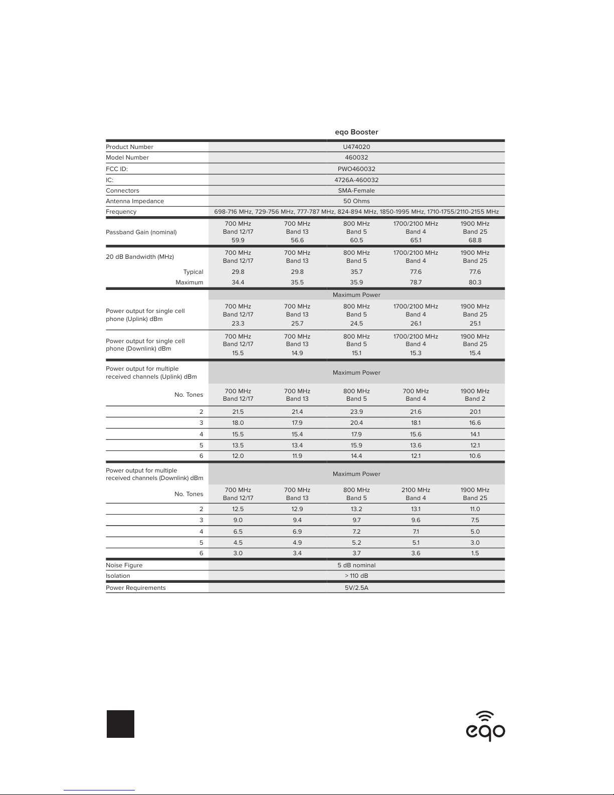
eqo Booster
Product Number U474020
Model Number 460032
FCC ID: PWO460032
IC: 4726A-460032
Connectors SMA-Female
Antenna Impedance 50 Ohms
Frequency
698-716 MHz, 729-756 MHz, 777-787 MHz, 824-894 MHz, 1850-1995 MHz, 1710-1755/2110-2155 MHz
Passband Gain (nominal)
700 MHz
Band 12/17
59.9
700 MHz
Band 13
56.6
800 MHz
Band 5
60.5
1700/2100 MHz
Band 4
65.1
1900 MHz
Band 25
68.8
20 dB Bandwidth (MHz)
700 MHz
Band 12/17
700 MHz
Band 13
800 MHz
Band 5
1700/2100 MHz
Band 4
1900 MHz
Band 25
Typical 29.8 29.8 35.7 77.6 77.6
Maximum 34.4 35.5 35.9 78.7 80.3
Maximum Power
Power output for single cell
phone (Uplink) dBm
700 MHz
Band 12/17
23.3
700 MHz
Band 13
25.7
800 MHz
Band 5
24.5
1700/2100 MHz
Band 4
26.1
1900 MHz
Band 25
25.1
Power output for single cell
phone (Downlink) dBm
700 MHz
Band 12/17
15.5
700 MHz
Band 13
14.9
800 MHz
Band 5
15.1
1700/2100 MHz
Band 4
15.3
1900 MHz
Band 25
15.4
Power output for multiple
received channels (Uplink) dBm
Maximum Power
No. Tones
700 MHz
Band 12/17
700 MHz
Band 13
800 MHz
Band 5
700 MHz
Band 4
1900 MHz
Band 2
2 21.5 21.4 23.9 21.6 2 0.1
3 18.0 17.9 20.4 18.1 16.6
4 15.5 15.4 17.9 15.6 14.1
5 13.5 13.4 15.9 13.6 12.1
6 12.0 11.9 14.4 12.1 10.6
Power output for multiple
received channels (Downlink) dBm
Maximum Power
No. Tones
700 MHz
Band 12/17
700 MHz
Band 13
800 MHz
Band 5
2100 MHz
Band 4
1900 MHz
Band 25
2 12.5 12.9 13.2 13.1 11.0
3 9.0 9.4 9.7 9.6 7.5
4 6.5 6.9 7. 2 7.1 5.0
5 4.5 4.9 5.2 5.1 3.0
6 3.0 3.4 3.7 3.6 1.5
Noise Figure 5 dB nominal
Isolation > 110 dB
Power Requirements 5V/2.5A
______
Specifications
The term “IC” before the radio certification number only signifies that Industry Canada technical specifications were met.
Each Signal Booster is individually tested and factory set to ensure FCC compliance. The Signal Booster cannot be adjusted without
factory reprogramming or disabling the hardware. The Signal Booster will amplify, but not alter incoming and outgoing signals in order
to increase coverage of authorized frequency bands only. If the Signal Booster is not in use for five minutes, it will reduce gain until
a signal is detected. If a detected signal is too high in a frequency band, or if the Signal Booster detects an oscillation, the Signal
Booser will automatically reduce the gain on that specific band.
The Manufacturer’s rated output power of this equipment is for single carrier operation. For situations when multiple carrier
signals are present, the rating would have to be reduced by 3.5 dB, especially where the output signal is re-radiated and can
cause interference to adjacent band users. This power reduction is to be by means of input power or gain reduction and not by an
attenuator at the output of the device.
Page 13
CELL PHONE SIGNAL BOOSTER
11
______
Safety Guidelines
To uphold compliance with network protection standards, all active cellular devices
must maintain at least six feet of separation distance from Inside Panel and Dome
antennas and at least four feet of separation distance from desktop and eqo Antenna.
Use only the power supply provided in this package. Use of a non-weBoost product
may damage your equipment.
The Signal Booster unit is designed for use in an indoor, temperature-controlled
environment (less than 100 degrees Fahrenheit). It is not intended for use in attics or
similar locations subject to temperatures in excess of that range.
RF Safety Warning: Any antenna used with this device must be located at least 8
inches from all persons.
AWS Warning: The Outside Antenna must be installed no higher than 31 feet 9 inches
(10 meters) above ground.
This is a CONSUMER device.
BEFORE USE, you MUST REGISTER THIS DEVICE with your wireless provider and have your
provider’s consent. Most wireless providers consent to the use of signal boosters. Some providers may not consent to the use of this device on their network. If you are unsure, contact your
provider.
You MUST operate this device with approved antennas and cables as specified by the manufacturer. Antennas MUST be installed at least 20 cm (8 inches) from any person.
You MUST cease operating this device immediately if requested by the FCC or a licensed wireless service provider.
WARNING. E911 location information may not be provided or may be inaccurate for calls served
by using this device.
This device may be operated ONLY in a fixed location for in-building use.
This device complies with Part 15 of FCC rules. Operation is subject to two conditions: (1) This device may not cause harmful
interference, and (2) this device must accept any interference received, including interference that may cause undesired operation.
Changes or modifications not expressly approved by weBoost could void the authority to operate this equipment.
FOR MORE INFORMATION ON REGISTERING YOUR SIGNAL BOOSTER WITH YOUR
WIRELESS PROVIDER, PLEASE SEE BELOW:
Sprint: http://www.sprint.com/legal/fcc_boosters.html
T-Mobile/MetroPCS: https://support.t-mobile.com/docs/DOC-9827
Verizon Wireless: http://www.verizonwireless.com/wcms/consumer/register-signal-booster.html
AT&T: https://securec45.securewebsession.com/attsignalbooster.com/
U.S. Cellular: http://www.uscellular.com/uscellular/support/fcc-booster-registration.jsp
Warnings
Page 14
12
CELL PHONE SIGNAL BOOSTER
2 YEAR WARRANTY
weBoost Signal Boosters are warranted for two (2) years against defects in
workmanship and/or materials. Warranty cases may be resolved by returning
the product directly to the reseller with a dated proof of purchase.
Signal Boosters may also be returned directly to the manufacturer at the
consumer’s expense, with a dated proof of purchase and a Returned Material
Authorization (RMA) number supplied by weoost. weBoost shall, at its option,
either repair or replace the product.
This warranty does not apply to any Signal Boosters determined by weBoost
to have been subjected to misuse, abuse, neglect, or mishandling that alters
or damages physical or electronic properties.
Replacement products may include refurbished weBoost products that have
been recertified to conform with product specifications.
RMA numbers may be obtained by contacting Customer Support
DISCLAIMER: The information provided by weBoost is believed to be complete and
accurate. However, no responsibility is assumed by weBoost for any business or
personal losses arising from its use, or for any infringements of patents or other rights
of third parties that may result from its use.
______
Warranty
Page 15
Cell Phone Signal Booster
https://cellphonesignalbooster.us/weboost-eqo-4g-cell-phone-booster-for-home-474120
Copyright © 2016 weBoost. All rights reserved.
weBoost products covered by U.S. patent(s) and pending application(s)
NOT AFFILIATED WITH WILSON ANTENNA
111976F_Rev02_04.06.20.17
 Loading...