

Page 1
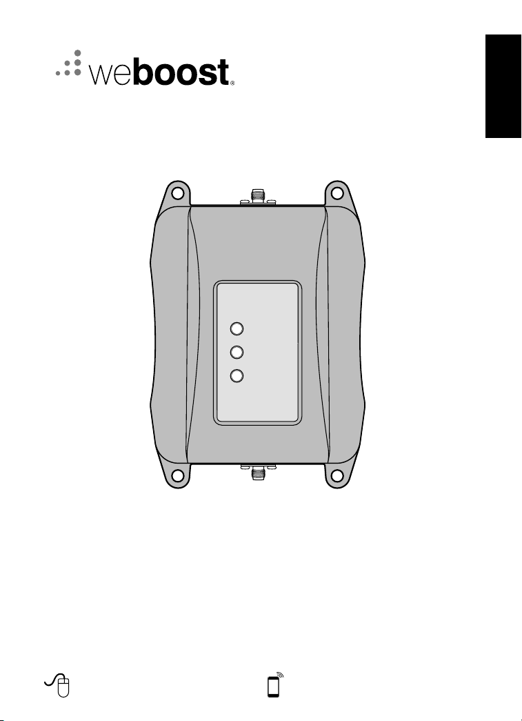
weBoost Drive AM100-Pro
Cellular Signal Booster
Multi-User Tri-Band
Page 2
ENGLISH
THE Drive AM100-Pro SIGNAL BOOSTER MAY REMAIN ON, IN VEHICLES WHOSE 12V DC POWER
SOURCES DO NOT AUTOMATICALLY SHUTDOWN WHEN THE VEHICLE IS TURNED OFF. THIS COULD
!
RESULT IN DISCHARGING THE VEHICLES BATTERY IN ONE TO TWO DAYS.
Installation Instructions for the Following weBoost Signal Boosters:
Drive AM100-Pro Signal Booster
Model #: AM100-Pro
Contents
Package Contents ....................................................3
Before Getting Started
Installation
Troubleshooting & Understanding Lights
Additional FAQ
Safety Guidelines
Signal Booster Specifications
Guarantee and Warranty
..........................................................3
................................................3
.................................5
.......................................................6
....................................................6
..........................................7
...................................... Back Cover
2
www.techlineglobal.com
Mon-Fri 8 am to 6 pm. Email: [email protected]
Page 3
ENGLISH
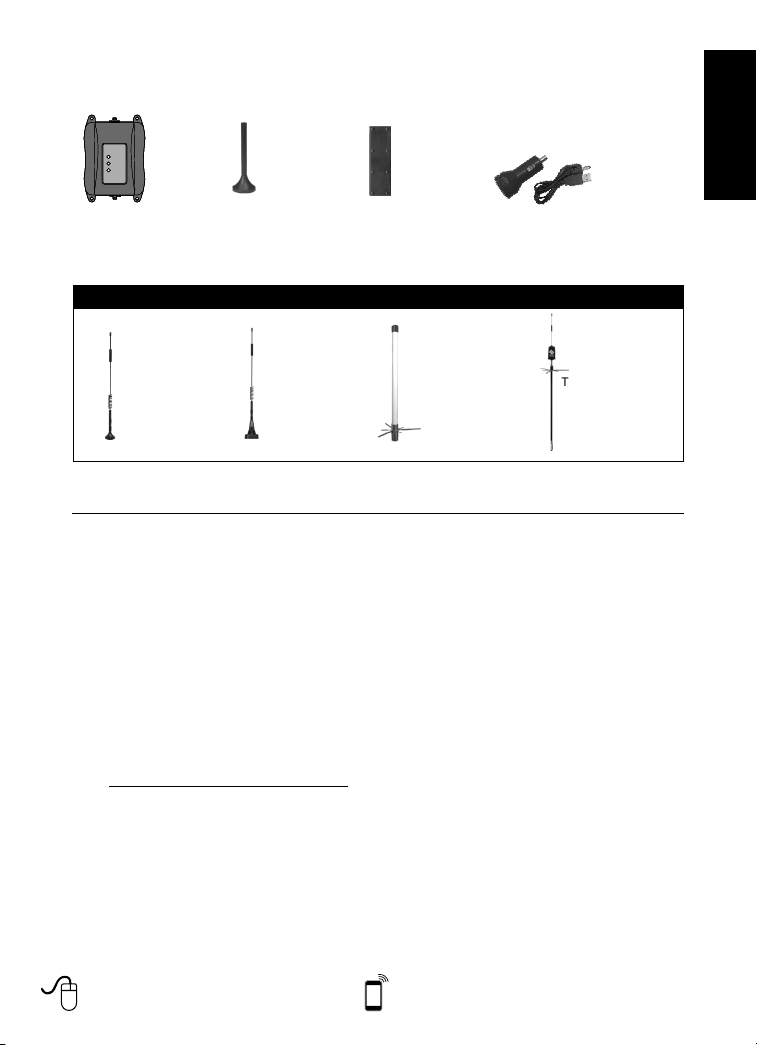
Package Contents
Drive AM100-Pro
Signal Booster
Optional Antennas
12” Mag Mount
Outside Antenna
Mini-Mag
Outside Antenna
Before Getting Started
Before you install your Drive AM100-Pro
Booster and start enjoying improved
cellular reception please do the following:
1. Read through all the installation
steps. This will help you know what
to expect from start to finish.
2. Watch the YouTube video
demonstrating the Drive AM100Pro Signal Boost installation at:
weboost.com/us/drive3G-M+video
3. Familiarize yourself with all
materials in your product package.
This will allow you to know which
pieces are referenced in the
instructions.
Slim Low Profile
Inside Antenna
NMO
Outside Antenna
Appearance of device and accessories may vary.
Marine
Outside Antenna
Installation
You can install your Drive AM100-Pro
Signal Booster in your vehicle using the
following steps. NOTE: Before completing
your installation, create a “soft” installation
by putting the components of your Drive
AM100-Pro Signal Booster in place and
testing the operation before mounting the
outside antenna. Select a location on top of
the car that is:
• Near the center of the vehicle’s roof.
• At least 30 cm from any other
antennas.
• Free of obstructions.
• At least 15 cm from any windows
(including sunroofs).
• At least 20 cm from any people.
DC Plug-In 5.5V/2A Power
Supply & USB CAble
Trucker
Outside Antenna
www.techlineglobal.com
Mon-Fri 8 am to 6 pm. Email: [email protected]
3
Page 4
ENGLISH
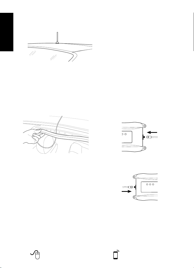
The outside antenna must be installed
vertically on a metallic surface.
2. Run the outside antenna cable
into the car. The cable is strong
enough that it may be shut in most
vehicle doors without damaging the
cable. For a cleaner look, carefully
pull down the door seal, run the
cable under the seal, and push the
seal back into place. This method
reduces wear on the cable as the
door opens and closes.
3. Install the Low-Profile inside antenna.
• Identify a place on the right side
of the driver’s seat to mount the
inside antenna. The location
should be at least 18 inches from
where the cellular device will be
used.
• Install the inside antenna at the
same angle as the cell phone
when held in use or near the
laptop’s cellular data card to
maximize signal strength.
For a more professional look,
you can install the inside antenna
underneath a car seat cover or
upholstery.
• When you have tested the
functionality of your Drive AM100Pro Signal Booster, mount the inside
antenna by peeling off the backing
of the Velcro® and attach it to your
selected location on the seat and
secure the inside antenna.
4. Place and connect the Drive AM100Pro Signal Booster.
• Select a location for the Signal
Booster that is free from excessive
heat, direct sunlight and moisture
and that has proper ventilation.
Good locations include underneath
a seat or under the dashboard.
• Connect the wire from the outside
antenna to the port labeled
“outside antenna” on the Signal
Booster.
• Connect the wire from the inside
antenna to the port labeled “inside
antenna” on the Signal Booster.
• Plug the power adapter into
vehicle’s 12V DC power supply
and attach the cord to the side of
Power Booster labeled “Power.”
NOTE: Do NOT connect the power
to the Signal Booster until you
have connected both the inside
and outside antennas.
4
www.techlineglobal.com
Mon-Fri 8 am to 6 pm. Email: [email protected]
Page 5
ENGLISH
Note: The Drive AM100-Pro Signal Booster
may remain on, in vehicles whose
12V DC power sources do not
automatically shutdown when the
vehicle is turned off. This could
result in discharging the vehicles
battery in one to two days.
Note: Some 12V DC power sources
are shut down when the vehicle
ignition is turned to off. Refer to
your vehicle owners manual for
specifics related to your vehicle.
NOTE: The plastic casing of your Signal
Booster will adjust to the temperature
of its environment, but is designed to
protect the Signal Booster technology.
For example, in the summer, the Signal
Booster case may be as hot as 150
degrees inside your vehicle. These
high temperatures will NOT damage
the Signal Booster, nor do they pose a
re risk to the vehicle. Again, be sure to
place your Signal Booster in a location
with adequate ventilation and away from
direct sunlight or moisture.
Troubleshooting &
Understanding Lights
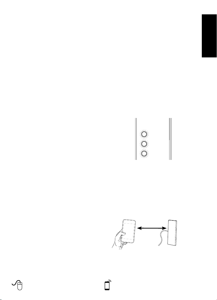
The lights on the front of the Drive
AM100-Pro Signal Booster indicate
whether the system is working or if there
are problems. Each light indicates the
operation of its labeled frequency. Take
the following steps based on the
indicator light color when using the Drive
AM100-Pro Signal Booster.
Lights off: If the lights are not on:
• Check connections on the power
supply to see that it is firmly plugged
into both the Drive AM100-Pro Signal
Booster and the power source.
• If using a DC power supply in your
vehicle, ensure the power supply is
www.techlineglobal.com
properly inserted. Then check the 12
volt power from the car socket and the
fuse. Replace the fuse if necessary.
Red light: A red light indicates oscillation
is occurring. Oscillation is similar to
feedback between a microphone and
speaker. When oscillation occurs, the
Signal Booster will power down to protect
the cell tower. To eliminate oscillation,
the outside antenna needs to be moved
farther from the inside antenna. Move the
outside antenna on the roof to the rear of
the car, but at least 20 to 30 cm from the
rear or side windows. Disconnect the
power from the Signal Booster, then
reconnect the power to reset the Signal
Booster.
Flashing red light: If one or more of the
lights on the Signal Booster are blinking
red, this means that the Signal Booster
has shutoff due to close proximity to the
handset or mobile device. Increase the
distance between the handset and the
Inside Antenna until the light is no longer
flashing red. Contact Customer Support
for assistance.
Increase
distance
Inside
antenna
Green light: A green light indicates the
Drive AM100-Pro Signal Booster is
working properly.
If you have additional questions about
Mon-Fri 8 am to 6 pm. Email: [email protected]
5
Page 6
ENGLISH
the operation of your Drive AM100-Pro
Signal Booster, please contact the local
Wilson Electronics Distributor support
team.
How does weather affect the
performance of my Outside Antenna?
Water vapor (e.g. rain, fog, snow or
other precipitation) creates an effective
lter to cellular signal. In times of
Additional FAQ:
heavy precipitation, you may see less
performance.
What hours can I contact tech
support?
Technical Support can be reached from
Mon-Fri 8 am to 6 pm, by email at
What’s the difference between the
2100 IMT (BAND 1), 1800 DCS ( Band
3), 900 E-GSM, GSM (Band 8)? How do
I know which MHz band my cell phone
uses?
The Drive AM100-Pro works with all
major South African cellular providers on
the 2100 IMT (BAND 1) / 1800 DCS
( Band 3) / 900 E-GSM, GSM (Band 8)
frequencies/bands. These frequencies/
bands are associated with voice, 3G and
4G data.
Safety Guidelines
WARNI NG: The Insi de Antennas must h ave 18 inche s of separ ation distanc e from all active u sers.
WARNI NG: Connecting the Signa l Boost er direc tly to th e cell ph one wit h use of an ad apter wi ll damag e the
WARNI NG: Use only t he power s upply pr ovided in this package. U se of a non -weBo ost pro duct may
WARNI NG: The Signal Booster unit is designed for use in an indoor, temperature-controlled environment
WARNI NG: The Outsi de Anten na must be i nstall ed no hig her than 10 meters (32 ’9”) above grou nd.
cell phone.
damage your equipment.
(less than 150 degrees Fahr enheit). I t is not intended fo r use in at tics, vehicl es or similar loc ations
subjec t to tempe rature s in exces s of that ra nge.
RF SAFETY WARNING: A ny antenna u sed wit h this dev ice mus t be loca ted at lea st 8 inches from all persons.
6
www.techlineglobal.com
Mon-Fri 8 am to 6 pm. Email: [email protected]
Page 7
ENGLISH
Signal Booster Specifications
Drive AM100-Pro
Product AM100-Pro
Model Number AM100-Pro
Connectors SMA
Antenna Impedance OHm 50
Frequency MHz 1920-1980 / 2110-2170 1710-1785 / 1805-1880 880-915 / 925-960
Bands B1 B3
Passband Gain UL/DL 53.9 / 53.7 49.8 / 51.8 49.3 / 50.1
20 dB Bandwidth (MHz)
Power output for single cell phone (dBm)
Power output for multiple received channels
(Uplink) dBm
Power output for multiple received channels
(Downlink) dBm
Noise Figure UL/DL 7.4 / 7.0 5.0 / 6.0 4.4 / 4.4
Isolation dB -65
Power Requirements 6 V, 1.5A
The Manufacturer
have to be reduced by 3.5 dB, especially where the output signal is re-radiated and can cause interference to adjacent band users. This power reduction is to
be by means of input power or gain reduction and not by an attenuator at the output of the device.
’s rated output power of this equipment is for single carrier operation. For situations when multiple carrier signals are present, the rating would
Typical
Maximum
Uplink
Downlink
No. Tones
2 20.2 21.2 20.3
3 18.4 19.4 18.5
4 17.2 18.2 17.3
5 16.2 17.2 16.3
6 15.4 16.4 15.5
No. Tones
2 2.8 3.2 2.6
3 1 1.4 0.8
4 -0.2 0.2 -0.4
5 -1.2 -0.8 -1.4
6 -2 -1.6 -2.2
74.8
77.4
20.2
85.6
86.7
2.8
21.2
3.2
B8
39.4
41.5
20.3
2.6
www.techlineglobal.com
Mon-Fri 8 am to 6 pm. Email: [email protected]
7
Page 8

1-Year Warranty
weBoost signal boosters are warranted for one (1) year against defects in workmanship and/or materials. Warranty
cases may be resolved by returning the product directly to the reseller with a dated proof of purchase.
Signal Boosters may also be returned directly to the local distributor at the consumer’s expense, with a dated proof
of purchase and a Returned Material Authorization (RMA) number supplied by Techline Global. weBoost shall, at its
ENGLISH
option, either repair or replace the product. Techline Global will pay for delivery of the repaired or replaced product
back to the original consumer if located within the various African regions.
This war ranty d oes not ap ply to any Si gnal Boo sters de termin ed by weBo ost to have be en subje cted to mi suse,
abuse, neglect, or mishandling that alters or damages physical or electronic pr operties.
Failure to use a surge protected AC Power Strip with at least a 1000 Joule rating will void your warranty.
RMA numbers may be obtained by contacting your local distribution partner.
Disclaimer: The infor mation provided b y weBoost i s believed to be compl ete and accurate. Ho wever, no respo nsibili ty
is assume d by weBoost for any busi ness or pe rsonal l osses ar ising from its use, o r for any infr ingements of
patents or o ther rig hts of third parti es that may result fro m its use.
Copyright © 2019 weBoost. All rights reserved.
U.S. Patent N os. – 7,221,96 7; 7,729,669; 7,486,9 29; 7,409,186; 7,783,318; 8,5 83,03 4; 8,583,03 3; 8,63 9,180
email: [email protected]
Website: www.techlineglobal.com
 Loading...