

Page 1
Connect 3G
Cellular Signal Booster
with Omni Antenna
™
Page 2
6
IT IS VERY IMPORTANT
! !
FALURE TO DO THIS W LL VO D YOUR WARRANTY
IN THE EVENT OF A POWER SURGE OR LIGHTN NG
STRIKE.
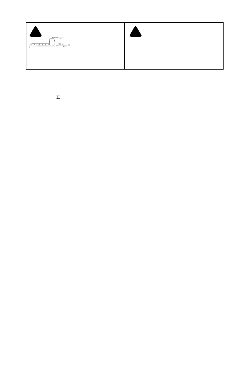
TO POWER YOUR SIGNAL
BOOSTER USING A SURGE
PROTECTED AC POWER
STR P WITH AT LEAST A 1000
JOULE RATING.
THE SIGNAL BOOSTER UNIT IS DESIGNED
FOR USE N AN NDOOR, TEMPERATURECONTROLLED ENV RONMENT (LESS
THAN 150 DEGREES FAHRENHEIT). IT IS
NOT NTENDED FOR USE N ATTICS OR S MILAR
LOCATIONS SUBJECT TO TEMPERATURES IN
EXCESS OF 150°F.
Installation Instructions for the Following weBoost Signal Booster:
Connect 3G Adjustable Gain In-Building Wireless 800/1900 MHz
SmarTech ™ Signal Booster
Model # 472005 FCC ID: PWO460005 IC: 4726A-460005
The term “IC” before the radio certification number only signifies that Industry Canada technical specifications were met.
Contents
Package Contents ....................................................... 3
Before Getting Started ................................................... 3
Find the Strongest Signal ................................................. 3
Installation Details ....................................................... 4
Quick Install ............................................................ 5
Outside Antenna Installation .............................................. 5
Signal Booster Installation ................................................ 6
Inside Antenna Installation ................................................ 6
Powering Up the Signal Booster ........................................... 6
Troubleshooting & Understanding Lights .................................... 7
Additional FAQ .......................................................... 8
Safety Guidelines ......................................................
Signal Booster Specifications .............................................11
10
Page 3
Package Contents
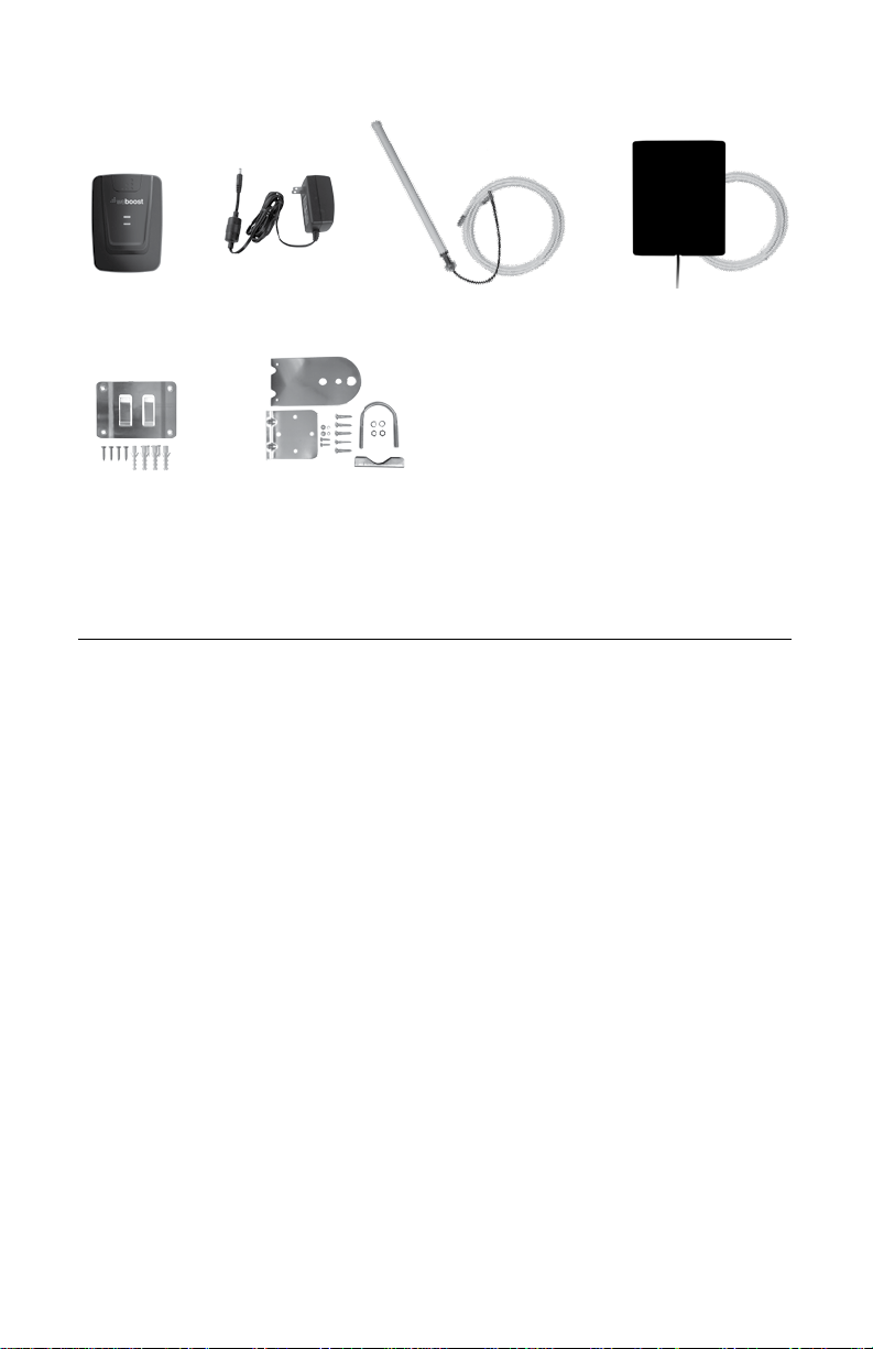
Connect 3G
AC Power Supply
(Not included with some models)
6V / 2 5A
(859912)
Outside Antenna Kit
20’ RG6 coax cable
(311201-0620)
Panel Antenna Kit
Inside Panel Antenna
30’ RG6 coax cable
(311155-0630)
Wall Mount Bracket
Omni Antenna Mount Bracket
Tools Required for Installation:
(depending on your particular installation, you will need the following tools)
1. Pole mount - 10 mm open-end wrench or adjustable wrench
2. W all mount or Rafter mount - Drill and 3/16 inch bit, Phillips-head screwdriver
Before Getting Started
Before you install your Connect 3G and
start enjoying improved cellular reception in
your facility, please do the following:
Read through all the installation steps.
This will help you know what to expect
from start to nish.
Familiarize yourself with all materials
in your product package. This will
allow you to know which pieces are
referenced in the instructions.
Identify the location of your best
available cellular signal. See
instructions that follow.
Determine the best installation
locations for your Outside Antenna,
Signal Boost, and Inside Antenna.
Test the function of your Connect 3G
system before nalizing installation.
Find the Strongest Cellular Signal
Before you install your Connect 3G signal
booster, you must determine the location of
the best available cellular signal. This will
affect the location of your Outside Antenna
and will help you get the best performance
from your Connect 3G. You can nd the
strongest signal outside your building,
typically at the highest point available, using
any of the following methods:
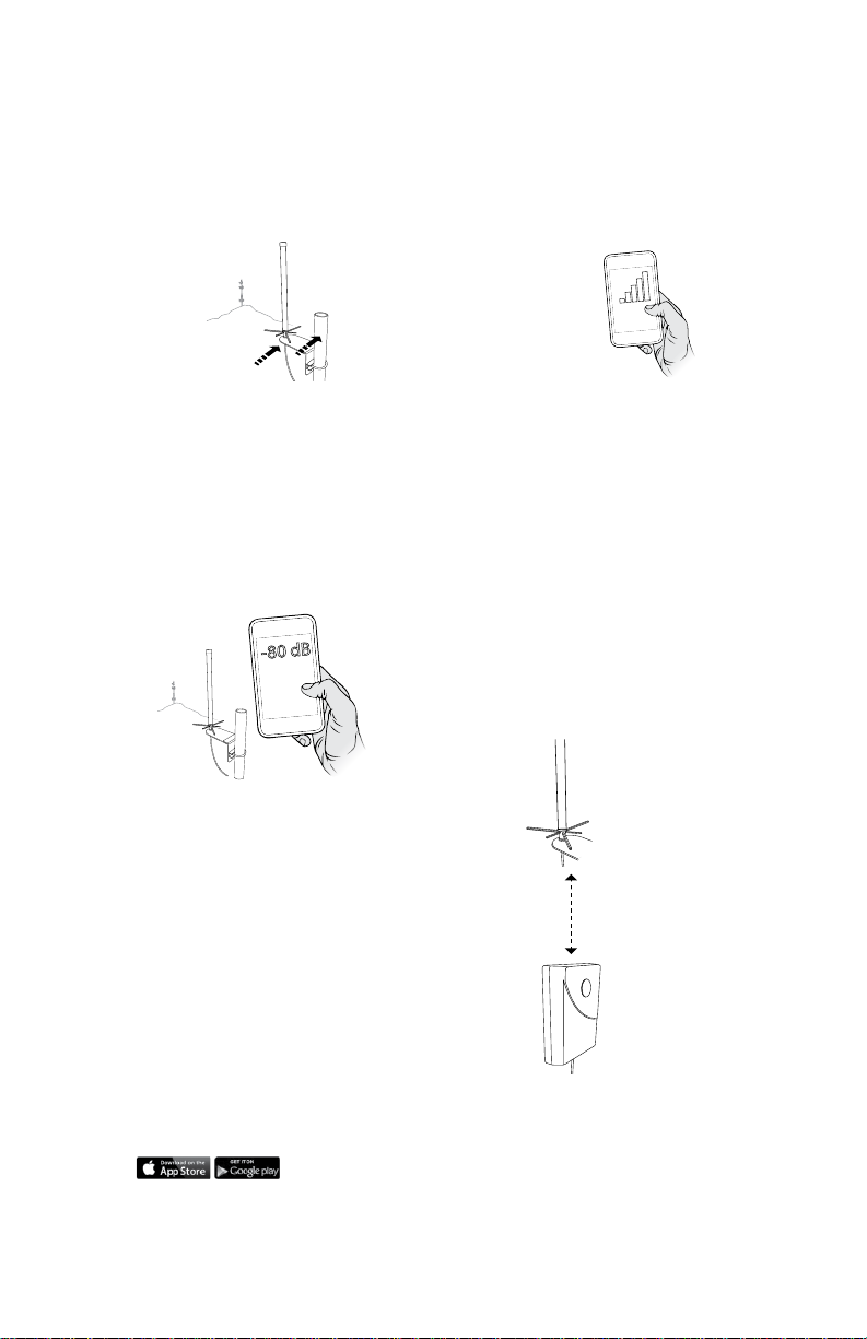
1. Best method:
Connect the Outside Antenna to the
Connect 3G signal booster, and the
Connect 3G to the Inside Antenna.
Have one person outside (on the roof for
best results) move the Outside Antenna
with a second person inside the building
near the Inside Antenna watching the
signal strength on a phone. This allows
you to read the signal strength from
nearby cell towers.
The person inside should have the
a.
phone in test mode so the numerical
signal strength can be read. This
is more accurate than the bar
indicator.
3
Page 4
4
b. The person on the roof should
move the Outside Antenna. Allow
30 seconds for the phone to register
with each location.
Outside Omni
Antenna
Cell Tower
Move
and note where the signal appears
the strongest. (Note: cell phone bars
are only an approximation of signal
strength and vary from phone to
phone.) Phones can take up to 30
seconds to reset to a new reading. Be
patient and repeat your signal check
several times.
WAIT 30
SECONDS
c. The person inside should note the
readings on the phone with each
placement. Signal readings usually
appear as a negative number. The
closer the number gets to zero, the
stronger the signal (for example,
-86 dB would be a moderately good
reading while -55 dB would be an
excellent reading, and -110 dB would
be a weak, or unusable signal).
Outside Omni
Antenna
Cell Tower
d. Once you have determined which
location provides the strongest
outside signal, you can install the
Outside Antenna in that general
location.
2. Good methods:
a. Place calls from several locations
outside your building. As you move
to different locations, note where
you get the best reception.
b. If you have a smart phone, you can
download apps that help you identify
locations of cell phone towers or
the strongest signal. Go to the App
Store and search for “cell signal” to
nd available apps for your device.
Installation Details
As you plan your installation, keep the
following guidelines in mind to maximize
your signal strength:
1. Maintain a vertical distance of at least
20 feet or a horizontal distance of at
least 50 feet between the Outside
Antenna to the Inside Antenna.
2. If poss ble, place the Inside Antenna
directly beneath the placement of the
Outside Antenna location. This creates
a maximized signal zone within the
room where the Inside Antenna is
located.
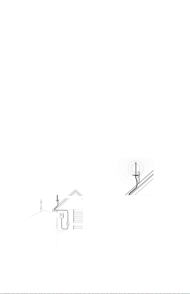
Outside Omni Antenna
Place the inside antenna
directly beneath the
placement of the Outside
Antenna location
At least 20 feet of vertical or
50 horizontal separation
Inside Panel Antenna
3. Be sure the Inside Antenna is NOT
facing toward the Outside Antenna.
This creates potential oscillation
3. Acceptable method: Check the bar
indicator on your cell phone display
Page 5
or feedback and reduces the
effectiveness of the Connect 3G.
We recommend you install the Lightning
Surge Protector (859992). Attach the
cable from the Outside Omni Antenna to
the surge protector and ground the surge
protector. The LSP is sold separately (refer
to page 11 for more info.
Quick Install
NOTE: Create a “soft” install rst by testing
components in your proposed locations
before securing them with hardware.
1. Select a location on the roof of the
building to install the Outside Antenna.
Make sure the antenna is clear of
obstructions that could block the signal
from the nearest cellular tower.
2. Select a location to install the Signal
Booster that is well ventilated and
away from excessive heat, moisture,
and direct sunlight.
3. Select a location for the Inside
Antenna that is in the center of the
area where the signal needs to be
amplied and a minimum of 20 vertical
feet or 50 horizontal feet from the
Outside Antenna.
another coax cable to the connector
labeled “Inside Antenna” and run it
to the Inside Antenna. NOTE: Be
careful not to bend the center pins
on the connectors when securing
connections.
5. Once you have ensured all
connections are tight, connect the
Signal Booster to a surge protected
power strip with at least a 1000 Joule
rating to protect your equipment from
power surges and lightning str kes
(refer to page 11 for information on
lightning protection).
6. If your Connect 3G is working
correctly, the lights will be green. If
the lights are orange or red, see the
“Troubleshooting” section starting on
page 7.
Outside Antenna Installation
1. Select a location on the roof or an
outside wall where the Outside
Antenna can be mounted without
obstruction (at least three feet of
clearance in all directions) and with at
least 20 feet of vertical or 50 feet of
horizontal separation from the Internal
Antenna.
Outside Omni Antenna
Inside Panel
Antenna
Connect 3G
4. Run the coax cable from the Outside
Antenna to the Signal Booster and
attach it to the connector labeled
“Outside Antenna.” Connect
2.
After connecting the coax cable to the
antenna, run it underneath the down side
of your roof’s ashing if mounted on the
roof. Tip: Often you can follow the route
used by satellite TV cables. If you attach
the Outside Antenna to a wall, run the
cable along the outside of the wall to the
area where you want the cable to appear
on the inside of the building, then drill a
hole through the wall where the cable will
enter the building. Caution: Before drilling
holes for the cable, be sure there are no
electrical outlets, wiring, or sewer or water
pipes you could puncture or sever.
3. Seal any holes with silicone, cable
bushings or other waterproof sealant.
5
Page 6
6
Signal Booster Installation
1. Select a location for the Signal
Booster that is away from excessive
heat, direct sunlight, moisture and well
ventilated. The enclosure must NOT
be air tight. Also, be sure the location
is near a power source.
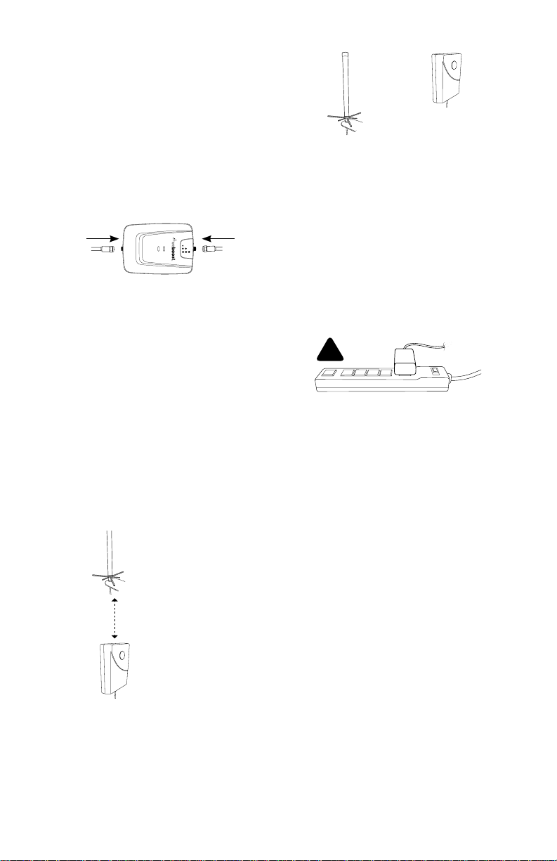
2. Connect the coax cables to the Signal
Booster from the Outside Antenna
and Inside Antenna at the designated
ports.
3. Do NOT connect the Signal Booster to
the power source until all cables are
connected.
Inside Antenna Installation
1. Select a location in the center of the
area where you want cellular signals
improved to mount the Inside Antenna.
If you have multiple rooms with poor
signal, you may need multiple Inside
Antennas. These can attach to the
Signal Boost by using a splitter (sold
separately). Contact weBoost for more
information.
2. Ensure a minimum of 20 feet vertical
or 50 horizontal feet separation from
the Outside Antenna.
Outside Omni Antenna
Face inside
antenna
away from
the outside
antenna.
Inside
Antenna
4. Use the mounting hardware included
in the package to secure the Inside
Antenna to the selected location.
Powering Up The Signal Booster
1. Ensure the cables to both the Outside
Antenna and Inside Antenna are
securely connected before powering
up the Signal Booster.
2. Plug the power supply into the Signal
Booster input marked “POWER” and
then into a surge protector power strip
with a minimum 1000 Joule rating.
!
3. The lights on the Signal Booster
should remain green . If the
lights are red or orange, see the
“Troubleshooting” section on page 7.
4. If you know that only one frequency
band (800 MHz or 1900 MHz) is
available in your coverage area,
reduce the gain control on the
frequency band that is NOT in use to
the lowest setting. This will reduce
power consumption of the Signal
Booster.
Place the inside antenna
directly beneath the
placement of the Outside
Antenna location
At least 20 feet of vertical or
50 horizontal separation
Inside Panel Antenna
3. Inside Antennas can be mounted
above ceiling drywall, on a ceiling
inside a room, or on a wall inside a
room. Ensure the Inside Antenna
is facing AWAY from the Outside
Antenna to avoid oscillation
(feedback).
Page 7
Troubleshooting &
Understanding Lights
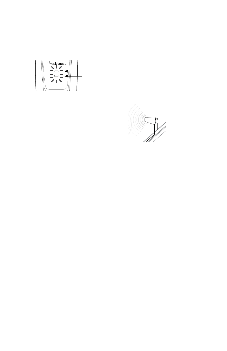
The Signal Boost includes four indicator
lights, one for each band (see FAQ for
explanation of MHz bands). Each indicator
light will either be green, orange or red.
Band 5
Band 2
Green indicates that the booster is
powered and operating at maximum
gain.
Solid Red indicates that the booster
has shut off on the associated
frequencies to prevent oscillation
(feedback).
Solid Orange indicates that the
booster has shut off on the associated
frequencies due to close proximity of
a cell tower.
Green/Orange Blinking indicates
that the booster is operating at a
reduced gain due to close proximity of
a cell tower.
Green/Red Blinking indicates that
the booster is operating at a reduced
gain to prevent oscillation (feedback).
Note: All red light issues must be resolved
before orange light issues.
Fixing Red Light Issues
If one or more lights on the Signal Boost
are red:
1. Make sure all connections are tight.
2. Increase the distance between the
outside antenna and the inside
antenna, by moving them horizontally
and/or vertically farther apart until the
light(s) change to green.
3. Follow the same steps for a green/red
blinking light until the light goes solid
green.
Fixing Orange Light Issues
If one or more lights on the Signal Booster
are orange:
1. Move the Outside Antenna away from
the strongest cellular signal in small
increments until the light turns green
or green/orange blinking.
Move the outside antenna
away from the strongest
cellular signal in small
increments
Lights Off
If one or more of the lights on the Signal
Booster are off verify power to your surge
protected power strip.
NOTE: The Signal Booster can be reset by
disconnecting and reconnecting the power
supply.
7
Page 8

6
Additional FAQ:
How does weather affect the
performance of my Outside Antenna?
Water vapor (e.g. rain, fog, snow or
other precipitation) creates an effective
lter to cellular signal. In times of
heavy precipitation, you may see less
performance.
What’s the difference between the 800
MHz and the 1900 MHz bands? How do
I know which MHz band my cell phone
uses?
The Connect 3G works with all major
North American cellular providers on
the 800 & 1900 MHz frequencies.
Traditionally, 800/1900MHz are associated
with voice and 3G data; while 700MHz
and 1700/2100MHz are associated
with 4G data.
Inside Antenna Expansion Kit
Kit 309900-50N
• 2 - Wall Panel antennas
• 1 - 50 ohm 3-Way Splitter
Kit 309905-50N
• 3 - Wall Panel Antennas
• 3 - 2-Way 50 Ohm Splitters
Kit 309902-75F
• 2 - Wall Panel Antennas
• 1 - 3-Way 75Ohm Splitter
Kit 309903-75F
• 3 - Wall Panel Antennas
• 3 - 2-Way 75Ohm Splitters
Kit 309904-75F
• 1 - Wall Panel Antenna
• 1 - 2-Way 75 Ohm Splitter
Inside Antenna Kits
Kit 301121-40010
• 50 Ohm Dome Antenna
• 10’ LMR400
Kit 311135-40060
• 50 Ohm Wall Panel Antenna
• 60’ LMR400
Kit 301151-0610
• 75 Ohm Dome Antenna
• 10’ RG6 Cable
Kit 311135-5820
• 50 Ohm Wall mount Panel Antenna
• 20’ RG58 Cable
Kit 311155-40060
• 50 Ohm Wall Mount Panel Antenna
• 60’ LMR400 Cable
Kit 301151-11 10
• 75 Ohm Dome Antenna
• 10’ RG1 1 cable
Kit 311155-1 150
• 75 Ohm Wall mount Panel Antenna
• 50’ RG1 1 Cable
Kit 301211
• Desktop Antenna w/ 5’ RG174
8
Page 9

50 Ohm Outside Antenna Kits
Kit 314453-5825
• 50 Ohm Pole Mount Panel Antenna
• 25’ RG58 Cable
Kit 314411-5825
• 50 Ohm Wide Band Directional
• 25’ RG58 Cable
Kit 30111 1-5850
• Yagi Direc ional Antenna
• 50’ RG58 Cable
Kit 311129-5840
• 8000 MHz Yagi Directional
• 40’ RG58 Cable
Kit 311203-5820
• Omni-Directional antenna
• 20’ RG58 Cable
Kit 311124-5830
• 1900 MHz Yagi Antenna
• 30’ RG58 Cable
Kit 311203-40020
• Omni-Directional antenna
• 20’ LMR400 Cable
Kit 30111 1-400170
• Yagi Direcional w/ N-Female
• 170’ LMR400
Kit 311124-400100
• 1900 MHz Yagi Directional
• 100’ LMR400 Cable
Kit 311129-400100
• 800 MHz Yagi Antenna
• 100’ LMR400 Cable
Kit 314411-40075
• 50 Ohm Wide Band Directional Antenna
• 75’ LMR400 Cable
Kit 314453-40075
• 50 Ohm Pole Mount Panel Antenna
• 75’ LMR400 Cable
Mini-Mag
• 301126 w/ 12.5 RG174 cable- SMA
75 Ohm Outside Antenna Kits
Kit 30111 1-0675
• Yagi Direc ional Antenna
• 75’ RG6 Cable
• N-Male to F-Female adapter
Kit 311201-0620
• Omni Antenna w/ F-Female
• 20’ RG6 Cable
Kit 311129-0660
• 800 MHz Yagi Directional
• 60’ RG6 Cable
• N-Male to F-Female adapter
Kit 311129-0650
• 1900 MHz Yagi Directional
• 50’ RG6 Cable
• N-Male to F-Female adapter
Kit 314473-0640
• 75 Ohm Pole Mount Panel Antenna
• 40’ RG6 Cable
Kit 311141-0620
• 75 Ohm Grey Brick Antenna
• 20’ RG6 Cable
Kit 30111 1-11 140
• Yagi Direc ional Antenna
• 140’ RG1 1 Cable
• N-Male to F-Female adapter
Kit 311201-1120
• Omni Directional w/ F-Female
• 20’ RG1 1 Cable
Kit 311129-1 11 10
• 800 MHz Yagi Directional
• 110’ RG11 Cable
• N-Male to F-Female adapter
Kit 311124-1 180
• 1900 MHz Yagi Directional
• 80’ RG1 1 Cable
• N-Male to F-Female adapter
Kit 314473-1175
• 75 Ohm Pole Mount Panel Antenna
• 75’ RG1 1 Cable
Kit 314475-0630
• 75 Ohm Wide Band Directional
• 30’ RG6 Cable
Kit 314475-1175
• 75 Ohm Wide Band Directional
• 75’ RG1 1 Cable
Kit 311141-1 120
• 75 Ohm Grey Brick Antenna
• 20’ RG1 1 Cable
9
Page 10
4
Safety Guidelines
WARNING To uphold compliance with network protection standards, all active cellular devices must
WARNING Connecting the Signal Booster directly to the cell phone with use of an adapter will damage the
WARNING Use only the power supply provided in this package. Use of a non-weBoost product may
WARNING The Signal Booster unit is designed for use in an indoor, temperature-controlled environment
WARNING Take care to ensure that neither you nor the pole comes near any power lines during
RF SAFETY W ARNING Any antenna used with this device must be located at least 8 inches from all
maintain at least 6 feet of separation distance from Panel and Dome antennas and 4 feet of
separation distance from desktop antennas.
cell phone.
damage your equipment.
(less than 150 degrees Fahrenheit). t is not intended for use in attics or similar locations
subject to temperatures in excess of that range.
installation.
persons.
This is a CONSUMER device.
BEFORE USE, you MUST REGISTER THIS DEVICE with your wireless provider
and have your provider’s consent. Most wireless providers consent to the use of
signal boosters. Some providers may not consent to the use of this device on their
network. If you are unsure, contact your provider.
You MUST operate this device with approved antennas and cables as specified by
the manufacturer. Antennas MUST be installed at least 20 cm (8 inches) from any
person.
You MUST cease operating this device immediately if requested by the FCC or a
licensed wireless service provider.
WARNING. E911 location information may not be provided or may be inaccurate
for calls served by using this device.
This devi ce compli es with Part 15 of FCC rules . Operati o n i s s u b j e c t t o two condi t ions: (1) This devic e m ay n o t cause
harmful interference, and (2) this device must accept any interference received, including interference that may cause
undesired operation. Changes or modifications not expressly approved by weBoost could void the authority to operate this
equipment.
Each Sig n a l B ooster is in d i v i d u a l l y te s t e d a n d f a c t o ry set to ens u r e FC C complian ce. The Sig n a l B o o s t e r cannot be
adjusted without factory reprogramming or disabling the hardware. The Signal Booster will amplify, but not alter incoming
and outgo i n g s ignals in or d e r t o i n c r e a s e coverage of a u t h o rized fre q u e n c y b ands only. If the S i g n a l B o oster is not in u s e
for five m i n u tes, it will re d u ce gain unti l a s i g n a l i s d et e cted. If a dete c t e d s i g n a l i s t o o h igh in a frequ e n c y b a n d , o r i f t h e
Signal B o o s t e r d e te cts an osci l l a t i o n , t h e S ignal Boo s te r w i l l a u t o m a t i cally tur n t h e p o we r o ff on that ba n d . Fo r a d e te cted
oscill a t i o n t h e Signal Bo o s te r will autom atically r e s u m e n o rmal oper ation afte r a m i n i m u m o f 1 m i nu t e. After 5 (fi v e) suc h
automat i c r e s t a rts, any pr o b l e m a t i c b a n d s a r e p e rmanentl y s h u t o ff until th e S i g n a l B ooster has b e e n m a n u a l ly r estart e d
by moment a rily remov i n g p o we r from the Si g n a l B ooster. Nois e p o we r, gai n , a n d l i n e a r i ty are maintained by th e S i g n a l
Booster’s microprocessor.
10
Page 11
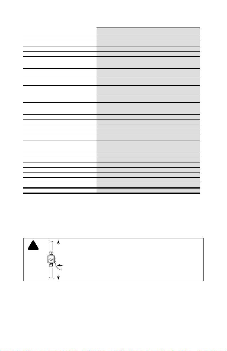
Signal Booster Specifications
™
Connect 3G
Model Number 472005
Connectors F-Female
Antenna Impedance 50 Ohms
Frequency 824-894 MHz / 1850-1990 MHz
Passband Gain (nominal)
20 dB Bandwidth (MHz)
Typical
Power output for single cell phone (dBm)
Power output for multiple received channels
(Uplink) dBm
Power output for multiple received channels
(Downlink) dBm
Noise Figure (typical downlink/uplink) 3 dB nominal / 6 dB nominal
Isolation > 90 dB
Power Requirements AC / DC 6V, 2.5A, w/2.5x5.5mm Jack
The Manufacturer’s rated output power of this equipment is for single carrier operation. For situations when multiple carrier signals are present, the rating
would have to be reduced by 3.5 dB, especialy where the output signal is re-radiated and can cause interference to adjacent band users. This power
reduction is to be by means of input power or gain reduction and not by an attenuator at the output of the device.
Maximum
Uplink
Downlink
No. Tones
2 24.8 20.2
3 21.3 16.7
4 18.8 14.2
5 16.9 12.3
6 15.3 10.7
No. Tones
2 1.3 3.5
3 -2.2 -0.1
4 -4.7 -2.6
5 -6.6 -4.5
6 -8.2 -6.1
800 MHz
Band 5
60.3
800 MHz
Band 5
40.8
41.1
800 MHz
Band 5
24.9
-2.2
800 MHz
Band 5
800 MHz
Band 5
1900 MHz
Band 2
60.4
1900 MHz
Band 2
74.7
75.0
1900 MHz
Band 2
22.5
-2.1
1900 MHz
Band 2
1900 MHz
Band 2
!
Lightning
Surge Protector
(sold separately)
To Outside
Antenna
Ground Wire
(not ncluded)
To Signal Booster
RECOMMENDED INSTALLING THE LIGHTNING SURGE PROTECTOR
(SOLD SEPARATELY)
NSTALL THE LIGHTNNG SURGE PROTECTOR (LSP) CLOSE TO THE SIGNAL
BOOSTER. ATTACH THE CABLE FROM THE OUTS DE ANTENNA TO THE
SURGE PROTECTOR. ENSURE THE LSP IS PROPERLY GROUNDED.
11
 Loading...