

Page 1
Need help? https://cellphonesignalbooster.us Customer Support
Mon.- Fri. Hours: 7 am to 6 pm MST
800-501-3153
ENGLISH
Cellular Signal Booster
Connect 4G
™
Page 2
2
Need help? https://cellphonesignalbooster.us Customer Support
Mon.- Fri. Hours: 7 am to 6 pm MST
800-501-3153
ENGLISH
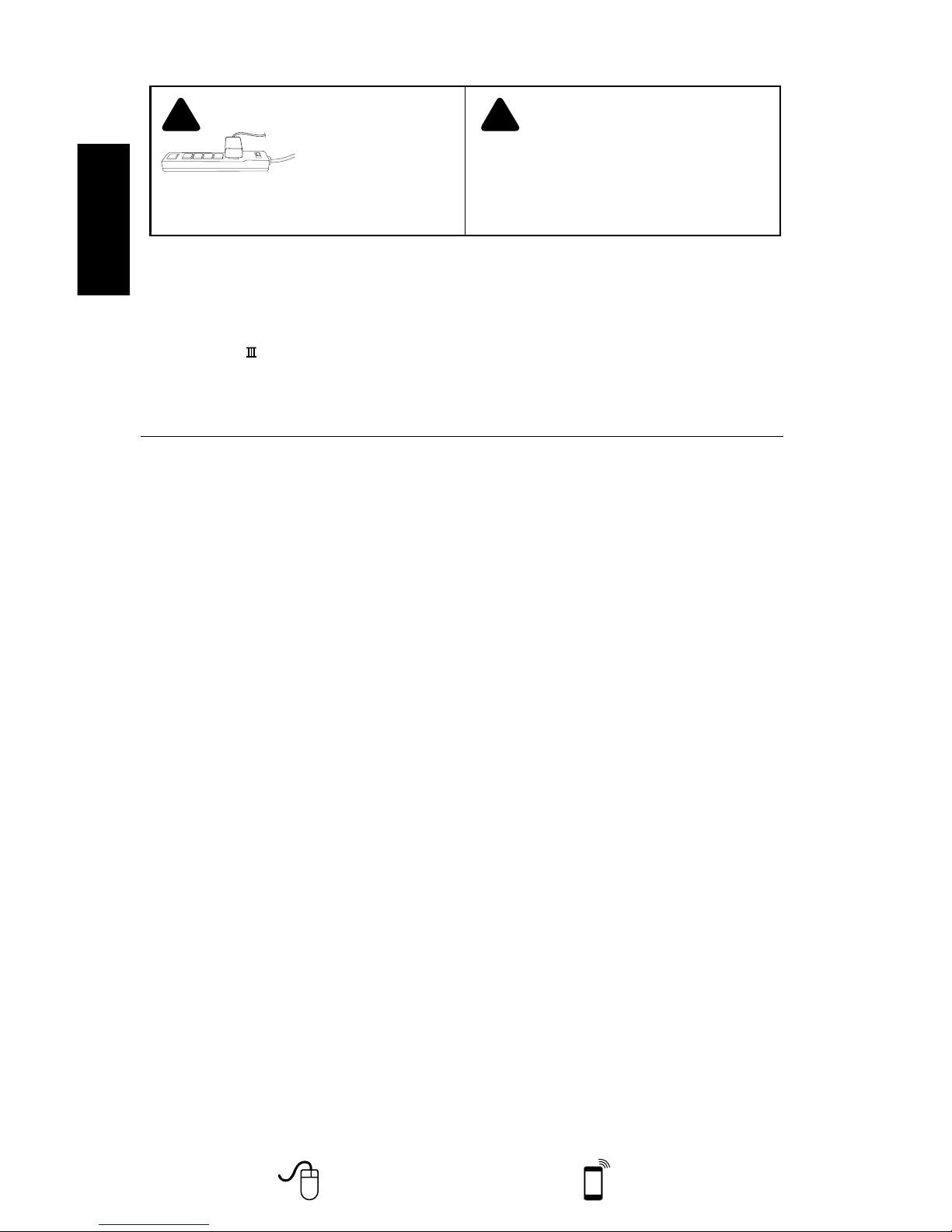
IT IS VERY IMPORTANT
TO POWER YOUR SIGNAL
BOOSTER USING A SURGE
PROTECTED AC POWER
STRIP WITH AT LEAST A 1000
JOULE RATING.
FAILURE TO DO THIS WILL VOID YOUR WARRANTY
IN THE EVENT OF A POWER SURGE OR LIGHTNING
STRIKE.
! !
THE SIGNAL BOOSTER UNIT IS DESIGNED
FOR USE IN AN INDOOR, TEMPERATURECONTROLLED ENVIRONMENT (LESS
THAN 150 DEGREES FAHRENHEIT). IT IS
NOT INTENDED FOR USE IN ATTICS OR SIMILAR
LOCATIONS SUBJECT TO TEMPERATURES IN
EXCESS OF 150°F.
Contents
Package Contents ..................................................... 3
Before Getting Started ................................................. 3
Find the Strongest Signal ............................................... 3
Installation Details ..................................................... 4
Quick Install .......................................................... 5
Outside Antenna Installation ............................................ 5
Signal Booster Installation .............................................. 6
Inside Antenna Installation .............................................. 6
Powering Up the Signal Booster ......................................... 6
Troubleshooting & Understanding Lights .................................. 7
Additional FAQ ........................................................ 8
Optional Equipment ................................................... 8
Safety Guidelines & Recommendations .................................. 10
Signal Booster Specifications .......................................... 11
Guarantee and Warranty ........................................ Back Cover
Installation Instructions for the Following weBoost Signal Booster:
Connect 4G™ Adjustable Gain 700 (Band 17,13) / 800 / 1900 (Band 25, Ext . PCS) / AWS
(1700 / 2100) MHz
Smar t Tech
™ Signal Booster
Model # 470003 FCC ID: PWO460001 IC 4726A- 460001
The term “IC” before the radio cer tif ication number only signifies that Industry Canada technical specific ations were met.
Page 3
Need help? https://cellphonesignalbooster.us Customer Support
Mon.- Fri. Hours: 7 am to 6 pm MST
800-501-3153
3
ENGLISH
Before Getting Started
Before you install your Connect 4G and
start enjoying improved cellular reception
in your facility, please do the following:
1. Read through all the installation
steps. This will help you know what to
2. Watch the YouTube video
demonstrating the Connect 4G
installation at
3. Familiarize yourself with all materials
in your product package. This will
allow you to know which pieces are
referenced in the instructions.
4. Identify the location of your best
available cellular signal. See
instructions that follow.
5. Determine the best installation
locations for your Outside Antenna,
Signal Boost, and Inside Antenna.
Test the function of your Connect 4G
Connect 4G™
Package Contents
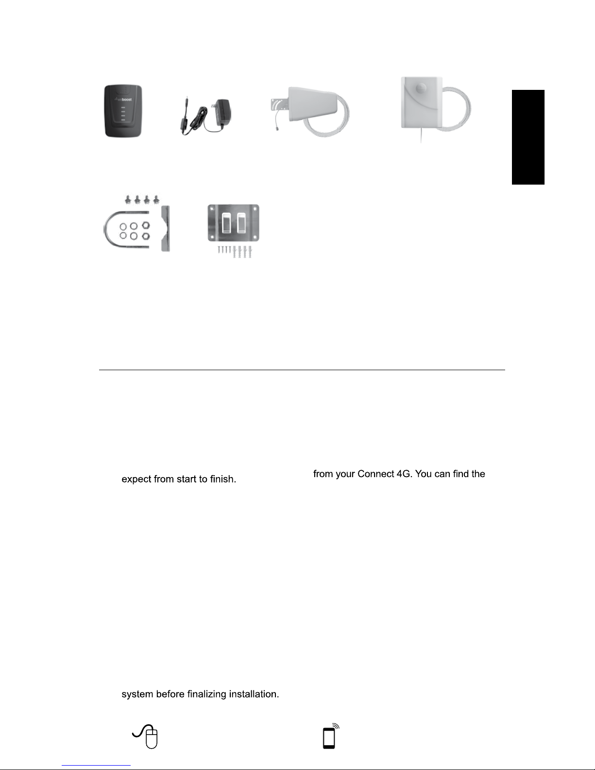
AC Power Supply
5V / 2.5A
(Not included with some models)
(859948)
Panel Antenna Kit
Inside Panel Antenna
30’ RG6 coax cable
(311155-0630)
Outside Antenna Kit
75 Ohm Wide Band Antenna
30’ RG6 coax cable
(314475-0630)
Tools Required for Installation:
(depending on your particular installation, you will need the following tools)
1. Pole mount - 10 mm open-end wrench or adjustable wrench
2. Wall mount or Rafter mount - Drill and 3/16 inch bit, Phillips-head screwdriver
Find the Strongest Cellular Signal
Before you install your Connect 4G signal
booster, you must determine the location of
the best available cellular signal. This will
affect the location of your Outside Antenna
and will help you get the best performance
strongest signal outside your building,
typically at the highest point available, using
any of the following methods:
1. Best method:
Connect the Outside Antenna to the
Connect 4G signal booster, and the
Connect 4G to the Inside Antenna.
Have one person outside (on the roof
for best results) rotate the Outside
Antenna with a second person inside
the building near the Inside Antenna
watching the signal strength on a
phone. This allows you to read the
signal strength from nearby cell towers.
a. The person inside should have
the phone in test mode so the
numerical signal strength can be
read. This is more accurate than
Appearance of device and accessories may vary.
Wall Mount BracketPole Mount Bracket
https://cellphonesignalbooster.us
Page 4
4
Need help? https://cellphonesignalbooster.us Customer Support
Mon.- Fri. Hours: 7 am to 6 pm MST
800-501-3153
ENGLISH
the bar indicator. Go to:
for your phone.
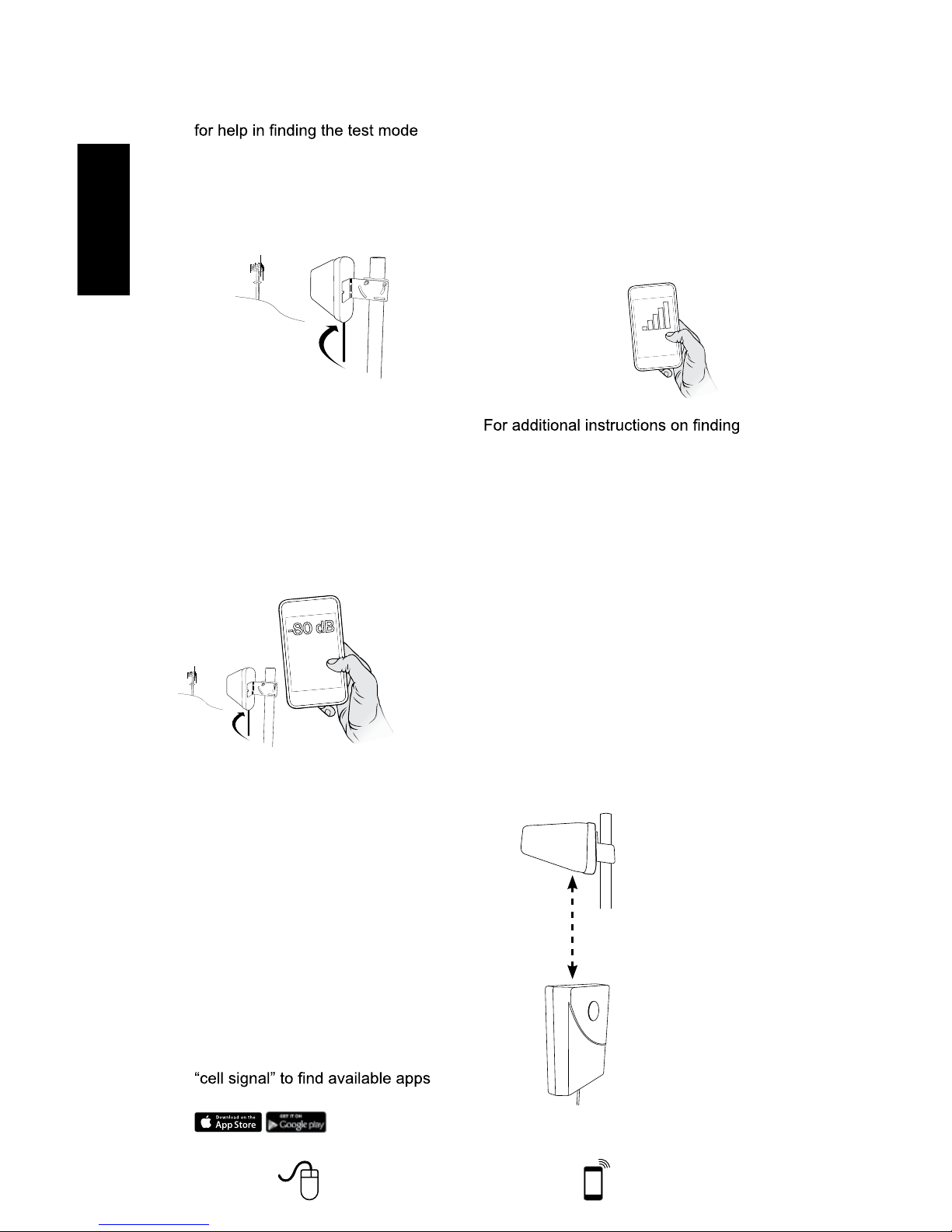
b. The person on the roof should turn
the Outside Antenna 45 degrees
at a time. Allow 30 seconds for the
phone to register with each turn.
R
o
t
a
t
e
c. The person inside should note the
readings on the phone with each
turn. Signal readings usually appear
as a negative number. The closer the
number gets to zero, the stronger the
signal (for example, -86 dB would be
a moderately good reading while -55
dB would be an excellent reading,
and -110 dB would be a weak, or
unusable signal).
R
o
t
a
t
e
d. Once you have determined which
direction provides the strongest
outside signal, you can install the
Outside Antenna in that general
direction.
2. Good methods:
a. Place calls from several locations
outside your building. As you move
to different locations, note where
you get the best reception.
b. If you have a smart phone, you
can download apps that help you
identify locations of cell phone
towers or the strongest signal. Go
to the App Store and search for
for your device.
3. Acceptable method: Check the bar
indicator on your cell phone display
and note where the signal appears
the strongest. (Note: cell phone bars
are only an approximation of signal
strength and vary from phone to
phone.) Phones can take up to 30
seconds to reset to a new reading. Be
patient and repeat your signal check
several times.
the strongest cellular signal, watch the
installation video at:
Installation Details
As you plan your installation, keep the
following guidelines in mind to maximize
your signal strength:
1. Maintain a vertical distance of at least
20 feet or a horizontal distance of at
least 50 feet between the Outside
Antenna to the Inside Antenna.
2. If possible, place the Inside Antenna
directly beneath the placement of
the Outside Antenna location. This
creates a maximized signal zone
within the room where the Inside
Antenna is located.
Place the inside antenna
directly beneath the
placement of the Outside
Antenna location
At least 20 feet of vertical or
50 feet horizontal separation
Outside Directional
Antenna
Inside Panel Antenna
WAIT 30
SECONDS
Cell Tower
Cell Tower
Outside Directional
Antenna
Outside Directional
Antenna
https://cellphonesignalbooster.us
https://cellphonesignalbooster.us
Page 5
Need help? https://cellphonesignalbooster.us Customer Support
Mon.- Fri. Hours: 7 am to 6 pm MST
800-501-3153
5
ENGLISH
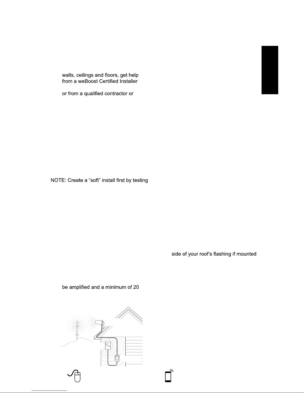
3. Be sure the Inside Antenna is NOT
facing toward the Outside Antenna.
This creates potential oscillation
or feedback and reduces the
effectiveness of the Connect 4G.
4. If you do not know how to mount
hardware or run coax cable through
at
electrician.
We recommend you install the Lightning
Surge Protector (859992). Attach the cable
from the Outside Directional Antenna to
the surge protector and ground the surge
protector. The LSP is sold separately.
Quick Install
For more detailed instructions on
installation, read the description later in
this guide or watch the video at:
components in your proposed locations
before securing them with hardware.
1. Select a location on the roof of
the building to install the Outside
Antenna. Make sure the antenna is
clear of obstructions that could block
the signal from the nearest cellular
tower.
2. Select a location to install the Signal
Booster that is well ventilated and
away from excessive heat, moisture,
and direct sunlight.
3. Select a location for the Inside
Antenna that is in the center of the
area where the signal needs to
vertical feet or 50 horizontal feet from
the Outside Antenna.
4. Run the coax cable from the Outside
Antenna to the Signal Booster and
attach it to the connector labeled
“Outside Antenna.” Connect another
coax cable to the connector labeled
“Inside Antenna” and run it to the
Inside Antenna. NOTE: Be careful
not to bend the center pins on
the connectors when securing
connections.
5. Once you have ensured all
connections are tight, connect the
Signal Booster to a surge protected
power strip with at least a 1000 Joule
rating to protect your equipment from
power surges and lightning strikes
(see page 11 for information on
lightning protection).
6. If your Connect 4G is working
correctly, the lights will be green. If
the lights are orange or red, see the
“Troubleshooting” section later in this
guide.
Outside Antenna Installation
1. Select a location on the roof or an
outside wall where the Outside
Antenna can be mounted without
obstruction (at least three feet of
clearance in all directions) and with at
least 20 feet of vertical or 50 feet of
horizontal separation from the Internal
Antenna.
2. After connecting the coax cable to the
antenna, run it underneath the down
on the roof. Tip: Often you can follow
the route used by satellite TV cables.
If you attach the Outside Antenna to a
wall, run the cable along the outside
of the wall to the area where you want
the cable to appear on the inside of
the building, then drill a hole through
the wall where the cable will enter
the building. Caution: Before drilling
holes for the cable, be sure there are
no electrical outlets, wiring, or sewer
or water pipes you could puncture or
sever.
3. Seal any holes with silicone, cable
bushings or other waterproof sealant.
Inside Panel
Antenna
Connect 4G
Outside Directional
Antenna
https://cellphonesignalbooster.us
https://cellphonesignalbooster.us
Page 6

6
Need help? https://cellphonesignalbooster.us Customer Support
Mon.- Fri. Hours: 7 am to 6 pm MST
800-501-3153
ENGLISH
3. Inside Antennas can be mounted
above ceiling drywall, on a ceiling
inside a room, or on a wall inside a
room. Ensure the Inside Antenna
is facing AWAY from the Outside
Antenna to avoid oscillation
(feedback).
Face inside
antenna
away from
the outside
antenna.
Inside
Antenna
4. Use the mounting hardware included
in the package to secure the Inside
Antenna to the selected location.
Powering Up The Signal
Booster
1. Ensure the cables to both the Outside
Antenna and Inside Antenna are
securely connected before powering
up the Signal Booster.
2. Plug the power supply into the Signal
Booster input marked “POWER” and
then into a surge protector power strip
with a minimum 1000 Joule rating.
!
3. The lights on the Signal Booster
should remain green . If the
lights are red or orange, see the
“Troubleshooting” section on page 7.
For illustrations of these installation steps,
view the install video at:
Signal Booster Installation
1. Select a location for the Signal
Booster that is away from excessive
heat, direct sunlight, moisture and
well ventilated. The enclosure must
NOT be air tight. Also, be sure the
location is near a power source.
2. Connect the coax cables to the
Signal Booster from the Outside
Antenna and Inside Antenna at the
designated ports.
3. Do NOT connect the Signal Booster
to the power source until all cables
are connected.
Inside Antenna Installation
1. Select a location in the center of
the area where you want cellular
signals improved to mount the Inside
Antenna. If you have multiple rooms
with poor signal, you may need
multiple Inside Antennas. These can
attach to the Signal Boost by using
a splitter (sold separately). Contact
weBoost for more information.
2. Ensure a minimum of 20 feet vertical
or 50 horizontal feet separation from
the Outside Antenna.
Place the inside antenna
directly beneath the
placement of the Outside
Antenna location
At least 20 feet of vertical or
50 feet horizontal separation
Outside Directional
Antenna
Inside Panel Antenna
https://cellphonesignalbooster.us
Page 7
Need help? https://cellphonesignalbooster.us Customer Support
Mon.- Fri. Hours: 7 am to 6 pm MST
800-501-3153
7
ENGLISH
Troubleshooting &
Understanding Lights
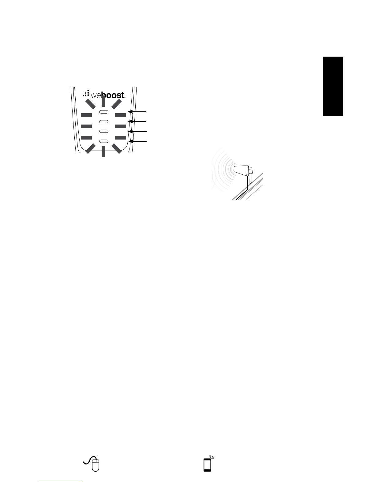
The Signal Boost includes four indicator
lights, one for each band (see FAQ for
explanation of MHz bands). Each indicator
light will either be green, orange or red.
Band 4
Band 5
Band 25/2
Band 12/13/17
Green indicates that the booster is
powered and operating at maximum
gain.
Solid Red indicates that the booster
has shut off on the associated
frequencies to prevent oscillation
(feedback).
Solid Orange indicates that the
booster has shut off on the associated
frequencies due to close proximity of
a cell tower.
Green/orange Blinking indicates that
the booster is operating at a reduced
gain due to close proximity of a cell
tower.
Green/red Blinking indicates that the
booster is operating at a reduced gain
to prevent oscillation (feedback).
Note: All red light issues must be resolved
before orange light issues.
Fixing Red Light Issues
If one or more lights on the Signal Boost
are red:
1. Make sure all connections are tight.
2. Increase the distance between the
outside antenna and the inside
antenna, by moving them horizontally
and/or vertically farther apart until the
light(s) change to green.
3. Follow the same steps for a green/red
blinking light until the light goes solid
green.
4. If more separation is not possible and
the coverage of the booster is too
small with a green/red blinking light
indicating reduced gain, contact the
weBoost Customer Support Team for
assistance: 800-501-3153.
Fixing Orange Light Issues
If one or more lights on the Signal Booster
are orange:
1. Move the Outside Antenna away from
the strongest cellular signal in small
increments until the light turns green
or green/orange blinking.
Move the outside antenna
away from the strongest
cellular signal in small
increments
2. If the light remains orange, or if the
green/orange blinking light indicating
reduced gain is not providing
enough coverage area, contact the
weBoost Customer Support Team for
assistance: 800-501-3153.
Lights Off
If one or more of the lights on the Signal
Booster are off verify power to your surge
protected power strip.
NOTE: The Signal Booster can be reset by
disconnecting and reconnecting the power
supply.
For additional descriptions on
troubleshooting, see the install video at
https://cellphonesignalbooster.us
Page 8
8
Need help? https://cellphonesignalbooster.us Customer Support
Mon.- Fri. Hours: 7 am to 6 pm MST
800-501-3153
ENGLISH
Inside Antenna Expansion Kit
Additional FAQ:
What hours can I contact customer support?
Customer Support can be reached from
7:00am to 6:00pm MST, by calling (800501-3153), or by email, at
How does weather affect the
performance of my Outside Antenna?
Water vapor (e.g. rain, fog, snow or
other precipitation) creates an effective
heavy precipitation, you may see less
performance.
What’s the difference between the 800
MHz and the 1900 MHz bands? How do
I know which MHz band my cell phone
uses?
The Connect 4G works with all major
North American cellular providers.
Traditionally, 800/1900MHz are associated
with voice and 3G data; while 700MHz
and 1700/2100MHz are associated
with 4G data. For more detail, refer to
Kit 301211 - Desktop Antenna w/ 5’ RG174
Kit 301121-40010
• 50 Ohm Dome Antenna
• 10’ LMR400
Kit 311135-40060
• 50 Ohm Wall Panel Antenna
• 60’ LMR400
Kit 301151-0610
• 75 Ohm Dome Antenna
• 10’ RG6 Cable
Kit 311135-5820
• 50 Ohm Wall mount Panel Antenna
• 20’ RG58 Cable
Kit 301151-1110
• 75 Ohm Dome Antenna
• 10’ RG11 cable
Kit 311155-1150
• 75 Ohm Wall mount Panel Antenna
• 50’ RG11 Cable
50 Ohm Outside Antenna Kits
Kit 314453-5825
• 50 Ohm Pole Mount Panel Antenna
• 25’ RG58 Cable
Kit 314411-5825
• 50 Ohm Wide Band Directional
• 25’ RG58 Cable
Kit 301111-5850
• Yagi Directional Antenna
• 50’ RG58 Cable
Kit 311129-5840
• 800 MHz Yagi Directional
• 40’ RG58 Cable
Inside Antenna Kits
Kit 309900-50N
• 2 - Wall Panel antennas
• 1 - 50 ohm 3-Way Splitter
Kit
309905-50N
• 3 - Wall Panel Antennas
• 3 - 2-Way 50 Ohm Splitters
Kit 309902-75F
• 2 - Wall Panel Antennas
• 1 - 3-Way 75Ohm Splitter
Kit 309903-75F
• 3 - Wall Panel Antennas
• 3 - 2-Way 75Ohm Splitters
Kit 309904-75F
• 1 - Wall Panel Antenna
• 1 - 2-Way 75 Ohm Splitter
https://cellphonesignalbooster.us
Page 9
Need help? https://cellphonesignalbooster.us Customer Support
Mon.- Fri. Hours: 7 am to 6 pm MST
800-501-3153
9
ENGLISH
Kit 301111-11140
• Yagi Directional Antenna
• 140’ RG11 Cable
• N-Male to F-Female adapter
Kit 311201-1120
• Omni Directional w/ F-Female
• 20’ RG11 Cable
Kit 311129-11110
• 800 MHz Yagi Directional
• 110’ RG11 Cable
• N-Male to F-Female adapter
Kit 311124-1180
• 1900 MHz Yagi Directional
• 80’ RG11 Cable
• N-Male to F-Female adapter
Kit 314473-1175
• 75 Ohm Pole Mount Panel Antenna
• 75’ RG11 Cable
Kit 314475-0630
• 75 Ohm Wide Band Directional
• 30’ RG6 Cable
Kit 314475-1175
• 75 Ohm Wide Band Directional
• 75’ RG11 Cable
Kit 311141-1120
• 75 Ohm Grey Brick Antenna
• 20’ RG11 Cable
Mini-Mag Outside Antenna
301126 w/12.5 RG174 cable-SMA
Kit 311203-5820
• Omni-Directional antenna
• 20’ RG58 Cable
Kit 311124-5830
• 1900 MHz Yagi antenna
• 30’ RG58 Cabl
e
Kit 311203-40020
• Omni-Directional antenna
• 20’ LMR400 Cable
Kit 301111-400170
• Yagi Directional w/ N-Female
• 170’ LMR400
Kit 311124-400100
• 1900 MHz Yagi Directional
• 100’ LMR400 Cable
Kit 311129-400100
• 800 MHz Yagi Antenna
• 100’ LMR400 Cable
Kit 314411-40075
• 50 Ohm Wide Band Directional Antenna
• 75’ LMR400 Cable
Kit 314453-40075
• 50 Ohm Pole Mount Panel Antenna
• 75’ LMR400 Cable
75 Ohm Outside Antenna Kits
Kit 301111-0675
• Yagi Directional Antenna
• 75’ RG6 Cable
• N-Male to F-Female adapter
Kit 311201-0620
• Omni Directional w/ F-Female
• 20’ RG6 Cable
Kit 311129-0660
• 800 MHz Yagi Directional
• 60’ RG6 Cable
• N-Male to F-Female adapter
Kit 311124-0650
• 1900 MHz Yagi Directional
• 50’ RG6 Cable
• N-Male to F-Female adapter
Kit 314473-0640
• 75 Ohm Pole Mount Panel Antenna
• 40’ RG6 Cable
Kit 311141-0620
• 75 Ohm G
rey Brick Antenna
• 20’ RG6 Cable
Page 10
10
Need help? https://cellphonesignalbooster.us Customer Support
Mon.- Fri. Hours: 7 am to 6 pm MST
800-501-3153
ENGLISH
Safety Guidelines
WARNING: To uphold compliance with networ k protection standards, all active cellular devices must maintain
at least 6 feet of separation distance from Panel Antennas, Dome Antennas and at least 4 feet of
separation distance from Desktop Antennas.
WARNING: Connecting the Signal Booster directly to the cell phone with use of an adapter will damage the
cell phone.
WARNING: Use only the power supply provided in this package. Use of a non-weBoost product may damage
your equipment.
WARNING: The Signal Booster unit is designed for use in an indoor, temperature-controlled environment
(less than 150 degrees Fahrenheit). It is not intended for use in attics or similar locations subject
to temperatures in excess of that range.
WARNING: Take care to ensure that neither you nor the pole comes near any power lines during installation.
WARNING: The outside antenna must be installed no higher than 10 meters (32 ’9”) above ground.
RF SAFETY WARNING: Any antenna used with this device must be located at least 8 inches from all persons.
BEFORE USE, you MUST REGISTER THIS DEVICE with your wireless provider
and have your provider’s consent. Most wireless providers consent to the use of
signal boosters. Some providers may not consent to the use of this device on their
network. If you are unsure, contact your provider.
You MUST operate this device with approved antennas and cables as specified by
the manufacturer. Antennas MUST be installed at least 20 cm (8 inches) from any
person.
You MUST cease operating this device immediately if requested by the FCC or a
licensed wireless service provider.
WARNING. E911 location information may not be provided or may be inaccurate
for calls served by using this device.
This is a CONSUMER device.
This devic e complies with Part 15 of FCC rules. Operation is subject to two conditions: (1) This device may not cause
harmful inter ference, and (2) this device must accept any interferenc e received, including interference that may
cause undesired operation. Changes or modifications not expressly approved by weBoost could void the authority to
operate this equipment.
Page 11
Need help? https://cellphonesignalbooster.us Customer Support
Mon.- Fri. Hours: 7 am to 6 pm MST
800-501-3153
11
ENGLISH
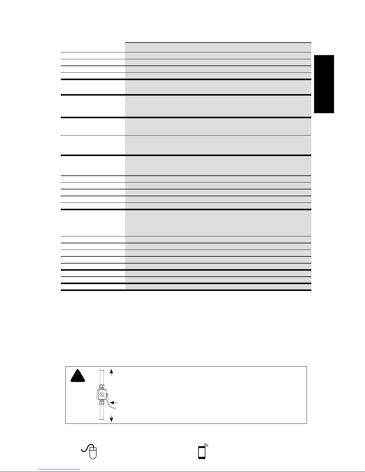
Lightning
Surge Protector
(sold separately)
To Outside
Antenna
To Signal Booster
Ground Wire
(not included)
!
RECOMMENDED: INSTALLING THE LIGHTNING SURGE PROTECTOR
(SOLD SEPARATELY)
INSTALL THE LIGHTNING SURGE PROTECTOR (LSP) CLOSE TO THE SIGNAL
BOOSTER. ATTACH THE CABLE FROM THE OUTSIDE ANTENNA TO THE
SURGE PROTECTOR. ENSURE THE LSP IS PROPERLY GROUNDED.
#859992-75 OHM MAY BE PURCHASED AT
HTTPS://CELLPHONESIGNALBOOSTER.US
OR BY CALLING 800-501-3153.
Signal Booster Specifications
Connect 4G
™
Model Number 470003
Connectors F-Female
Antenna Impedance 50 Ohms
Frequency 704-746 MHz, 746-787 MHz, 824-894 MHz, 1850-1995 MHz, 1710-1755/2110-2155 MHz
Passband Gain (nominal)
700 MHz
Band17
57.3
700 MHz
Band13
55.0
800 MHz
Band 5
57.2
1700/2100 MHz
Band 4
60.5
1900 MHz
Band 25/2
57.0
20 dB Bandwidth (MHz)
700 MHz
Band17
700 MHz
Band13
800 MHz
Band 5
1700/2100 MHz
Band 4
1900 MHz
Band 25/2
Typical
Maximum
26.2
29.8
26.7
29.8
38.3
39.5
73.5
73.8
78.4
80.1
Power output for single cell
phone (Uplink) dBm
700 MHz Band17
Band17
700 MHz Band13
Band13
800 MHz
Band 5
1700 MHz
Band 4
1900 MHz
Band 25/2
23.7 23.6 24.6 24.9 23.3
Power output for single cell
phone (Downlink) dBm
700 MHz Band17
Band17
700 MHz Band13
Band13
800 MHz
Band 5
2100 MHz
Band 4
1900 MHz
Band 25/2
0.9 -1.0 2.1 5.8 6.1
Power output for multiple
received channels (Uplink) dBm
No. Tones
Maximum Power
700 MHz Band17
Band17
700 MHz Band13
Band13
800 MHz
Band 5
1700 MHz
Band 4
1900 MHz
Band 25/2
2 21.3 20.7 23.0 19.9 18.1
3 17.7 17.2 19.4 16.4 14.6
4 15.2 14.7 16.9 13.9 12.1
5 13.3 12.8 15.0 11.9 10.2
6 11.7 11.2 13.4 10.4 8.6
Power output for multiple
received channels
(Downlinklink) dBm
Maximum Power
No. Tones
700 MHz
Band17
700 MHz
Band13
800 MHz
Band 5
2100 MHz
Band 4
1900 MHz
Band 25/2
2 -2.0 -3.2 1.8 -0.5 -2.2
3 -5.6 -6.7 -1.7 -4.1 -5.8
4 -8.1 -9.2 -4.2 -6.6 -8.3
5 -10.0 -11.2 -6.1 -8.5 -10.2
6 -11.6 -12.8 -7.7 -10.1 -11.8
Noise Figure 7 dB nominal
Isolation > 110 dB
Power Requirements AC / DC 5V, 2.5A, w/2.5x5.5mm Jack
Eac h Sign al Boo ste r is ind ivi dua lly tes ted and fac tory set t o en sur e FC C comp lianc e. T he Sig nal Boost er c an not b e adjusted w ith out fac tor y
repro gra mming or disabl ing the hardw are . Th e Signal Boo ste r will amp lif y, bu t no t alt
er inc oming and outgo ing sig nals i n or der to inc rea se
cover age of a uth orized fr equen cy ban ds only. I f th e Sign al Boo ste r is not i n us e for f ive min ute s, i t will r edu ce g ain unt il a si gna l is dete cted.
If a d ete cte d sign al i s too hi gh i n a f requency band, or i f th e Sign al Boo ste r de tec ts a n os ci llati on, the Signa l Boos ter will automatica lly tur n
the pow er o ff o n that ban d. Fo r a dete cted o sci llati on the Signa l Boos ter will automat ica lly res ume n
orm al ope ratio n af te r a m inimu m of 1
minute. Af ter 5 (f ive) suc h au tom ati c re sta rt s, a ny p roblema tic bands are perma nentl y sh ut of f until t he Signa l Boos ter has bee n ma nua lly
res tar te d by m om ent arily r emo vin g power fr om t he Sig nal Booster. N oise p owe r, gai n, a nd l inear it y are maintai ned by the Signal Boost er’s
mic ropro ce sso r.
The Man ufa cture r’s r ated output p owe r of thi s eq uipme nt is for singl e c arr ie r oper ation. For sit uat ions when multiple c arrie r
sig nals are
pre sent, the rat ing wou ld h ave to b e re duc ed by 3. 5 d B, especi all y wher e th e ou tpu t si gna l is re -r adi ated a nd c an cau se inte rferenc e to
adjace nt band us ers . Th is p ower re duc tion i s to be by mea ns o f inp ut p owe r or gai n reducti on a nd not b y an a tt enu ator a t th e ou tpu t of t he
device.
Page 12
Disclaimer:
The information provided by weBoost is believed to be complete and accurate. However, no responsibility is assumed
by weBoost for any business or personal losses arising from its use, or for any infringements of patents or other rights
of third parties that may result from its use.
2-Year Warranty
weBoost Signal Boosters are warranted for two (2) years against defects in workmanship and/or materials. Warranty
cases may be resolved by returning the product directly to the reseller with a dated proof of purchase.
Signal Boosters may also be returned directly to the manufacturer at the consumer’s expense, with a dated proof of
purchase and a Returned Material Authorization (RMA) number supplied by weBoost. weBoost shall, at its option,
either repair or replace the product. weBoost will pay for delivery of the repaired or replaced product back to the original
consumer if located within the continental U.S.
This warranty does not apply to any Signal Boosters determined by weBoost to have been subjected to misuse, abuse,
neglect, or mishandling that alters or damages physical or electronic properties.
Failure to use a surge protected AC Power Strip with at least a 1000 Joule rating will void your warranty.
RMA numbers may be obtained by contacting Customer Support at 800- 501-315 3.
Copyright © 2014 weBoost. All rights reserved.
weBoost products covered by U.S. patent(s) and pending application(s)
 Loading...