

Page 1
A WILSON ELECTRONICS BRAND
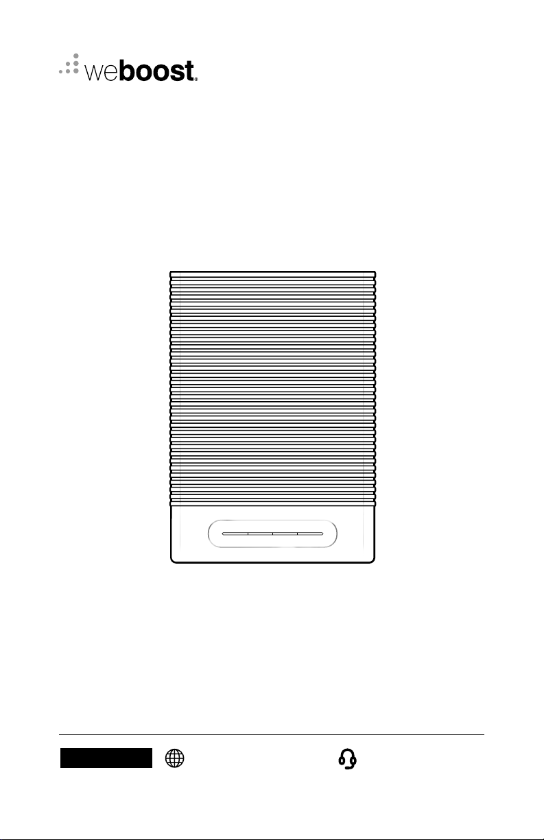
Home Complete
Cellular Signal Booster
NEED HELP?
User Manual
support.weboost.com 866.294.1660
Page 2
______
Index
Package Contents
Preparation
STEP 1-A & B: Connect Inside Antenna To Booster
STEP 2-A: Point Outside Antenna Toward Nearest Cell Tower
STEP 2-B: Mount Bracket To Outside Antenna
STEP 3: Route & Connect Cable To System
STEP 4: Power Up The Booster & Optimize The System
Measuring Booster Performance
Light Patterns
Troubleshooting
1
2
3
4
5
6
7
9
11
12
Safety Guidelines
Specifi cations
Warranty
14
16
17
Page 3
______
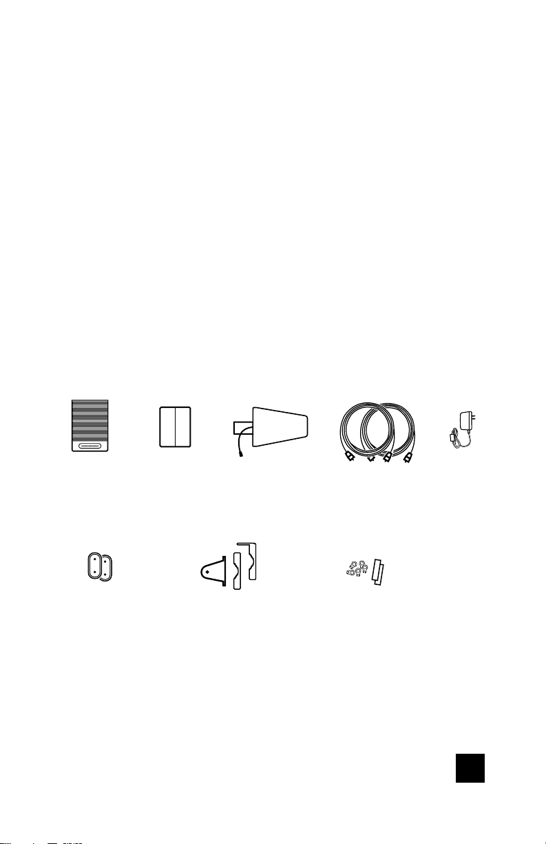
Package
Contents
Home
Complete
Booster
Booster &
Inside Antenna
Mounts
HOME COMPLETE CELL PHONE SIGNAL BOOSTER
Inside
Antenna
Outside Antenna
Bracket
Mount
Outside
Antenna
75’ & 60’
Cables
Cable Clips
& 2 Adhesive
Strips
Power
Supply
1
Page 4
______
Preparation
You Will Need (tools not included)
Make sure the following materials are prepared and ready for your
installation.
3 to 4 hours
2 people (a person to help with antenna calibration)
Ladder
Phillips-head screwdriver
10mm open-end wrench or adjustable wrench
Drill (if routing cable through wall)
1.25”-2” diameter pole existing pole (or order #901117)
Recommended: Power Strip with surge protection
NOTE: These instructions will walk you through a “soft” install process to fi nd
the optimal locations for the inside and outside antennas, then through the
process of the permanent installation.
2
CELL PHONE SIGNAL BOOSTER HOME COMPLETE
Page 5
______
Step 1-A & B: Connect Inside
Antenna To Booster
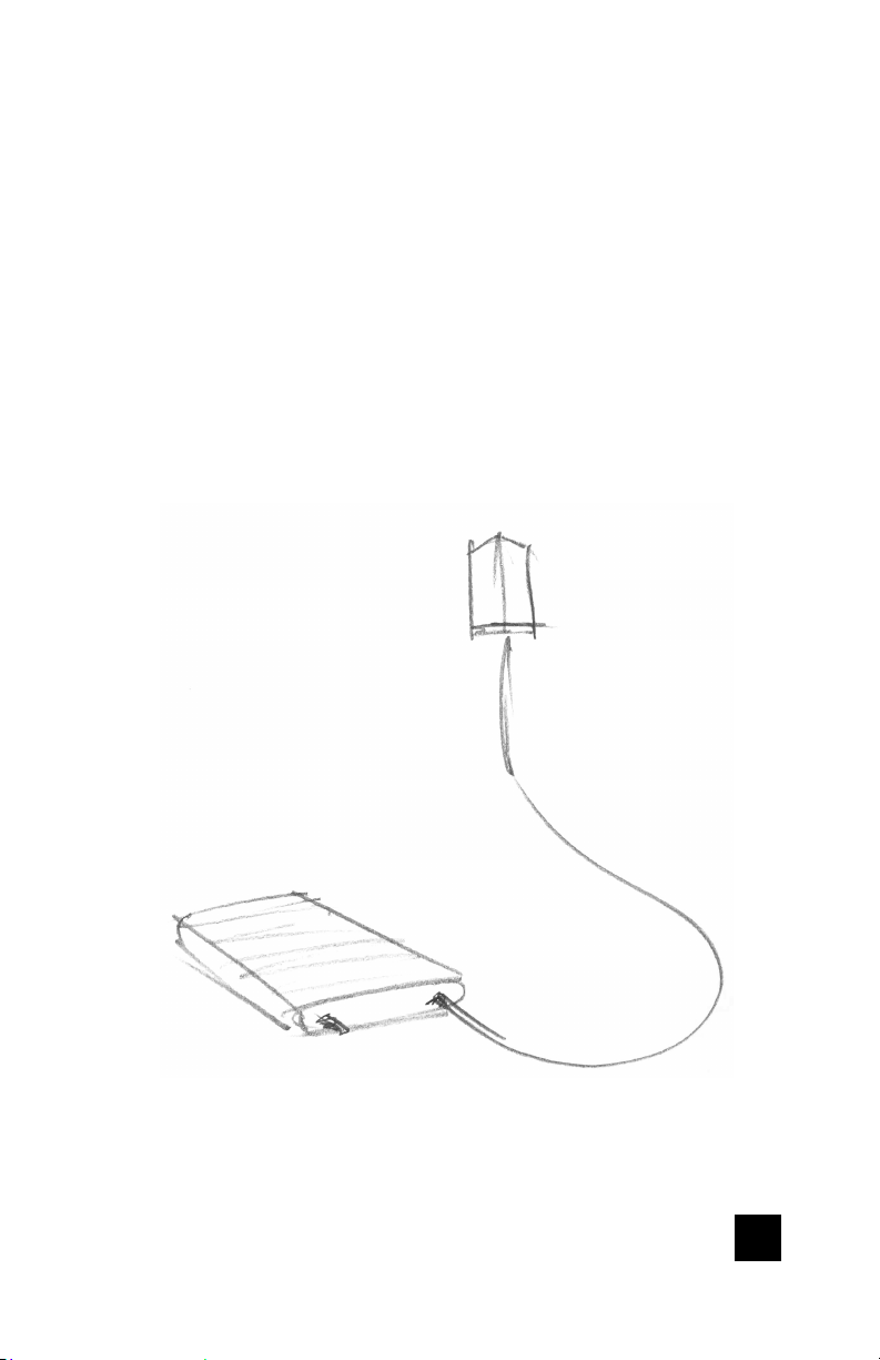
Place the Inside Antenna where you need the greatest signal boost.
Connect Inside Antenna cable to the supplied coax cable then to the
bottom port on Home Complete Booster labeled ‘INSIDE’ and place Inside
Antenna in weak signal area at least 18 inches away from booster.
NOTE: Do not connect booster to power until the system is fully installed.
Inside
Antenna
Booster
HOME COMPLETE CELL PHONE SIGNAL BOOSTER
3
Page 6
______
Step 2-A: Point Outside
Antenna Toward Nearest
Cell Tower
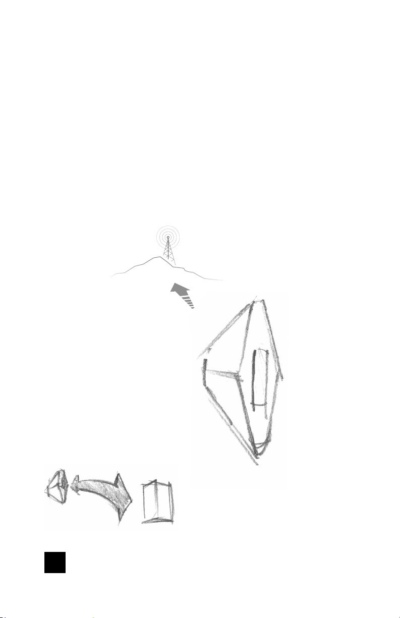
Point the Outside Antenna toward the nearest cell phone tower. To fi nd the
nearest tower, use an app such as ‘Open Signal’. This is the most critical step
of the installation process because it will determine the overall performance
of the booster system. The greater the separation between the Inside and
Outside Antennas, the better performance you will get from the booster.
Cell Tower
Outside Antenna
NOTE: The Outside Antenna must be at least
50 feet horizontal or 20 feet vertical from the
Inside Antenna for best performance. Make
sure the Inside Antenna and Outside Antennas
are setup so they are facing away from
each other.
4
CELL PHONE SIGNAL BOOSTER HOME COMPLETE
Page 7
______
Step 2-B: Mount Bracket To
Outside Antenna
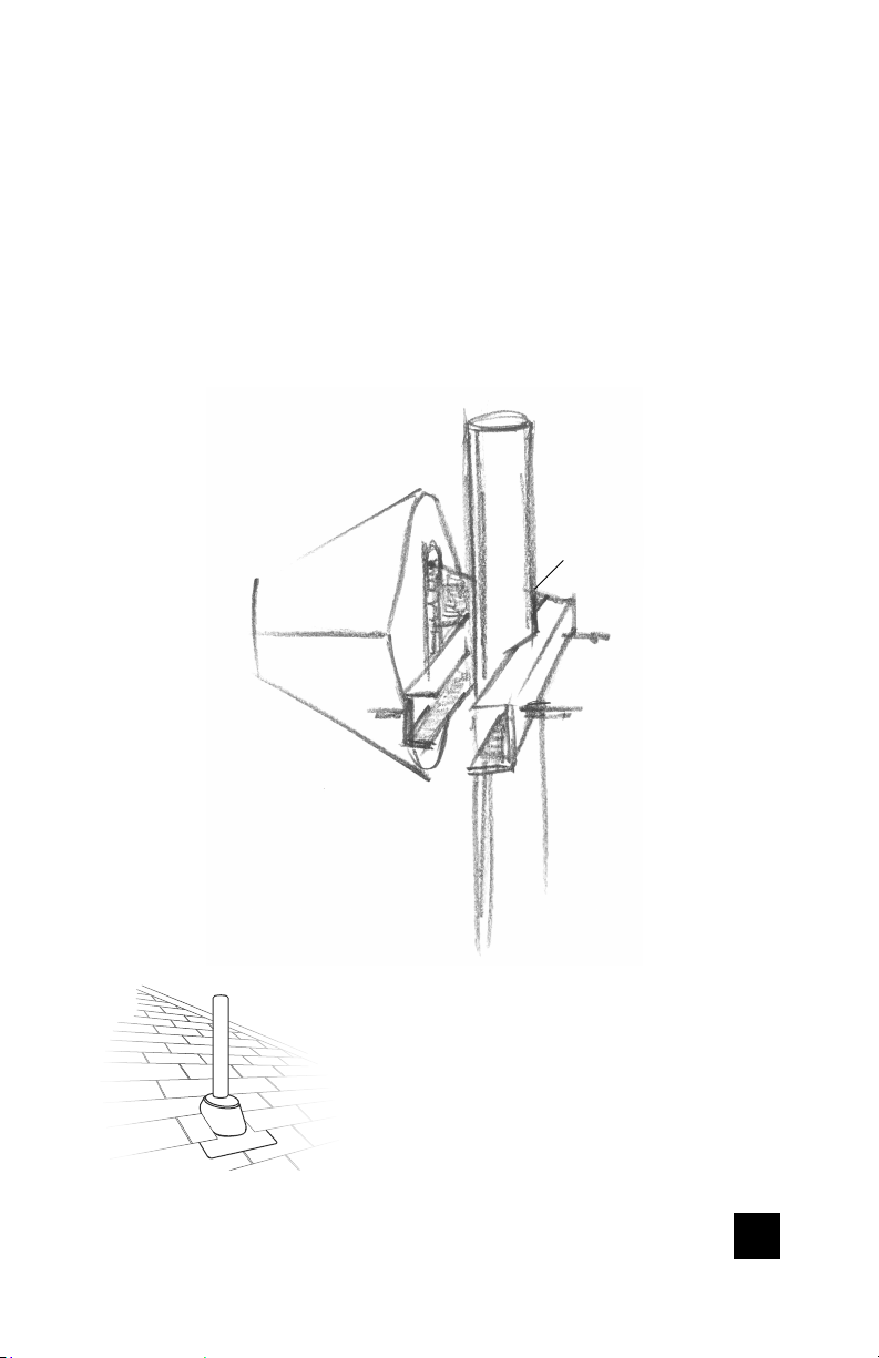
Attach the Mount to the Outside Antenna and use the Bolts/Pole Bracket to
attach to a pole.
Outside Antenna
Drip holes
face down
Pole
(1.25”-2.0”dia.)
Antenna Mount
Pole Bracket
NOTE: Mounting on existing roof exhaust pipe
would be a good time-saver option. Watch out for
power lines.
HOME COMPLETE CELL PHONE SIGNAL BOOSTER
5
Page 8
______
Step 3: Route & Connect
Cable To System
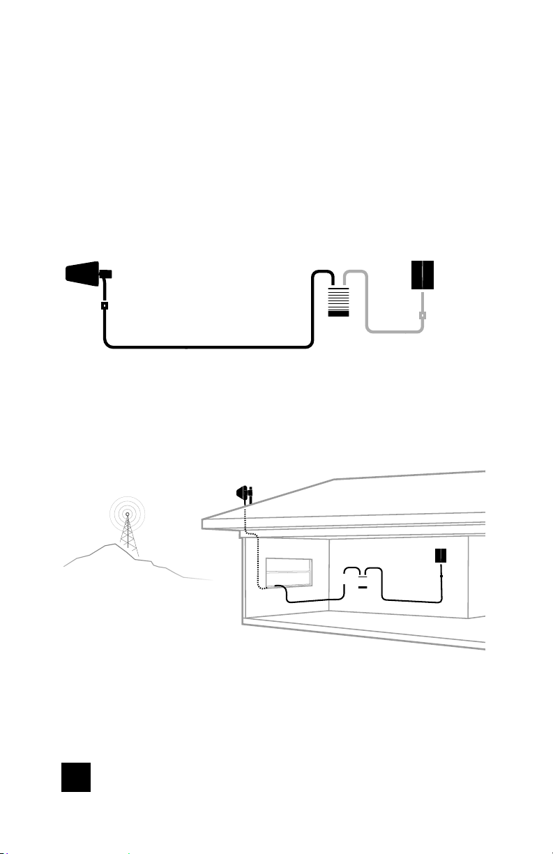
Connect the white RG-11 Cable to Outside Antenna and route cable
into the home. All connections should be hand tightened only.
Outside
Antenna
Booster
RG-11 Cable
Route cable to the Home Complete Booster and connect to port
labeled ‘OUTSIDE’.
Outside
Antenna
Cell
Tower
Inside
Antenna
Booster
Inside
Antenna
6
CELL PHONE SIGNAL BOOSTER HOME COMPLETE
Page 9
______
Step 4: Power Up The
Booster & Optimize
The System
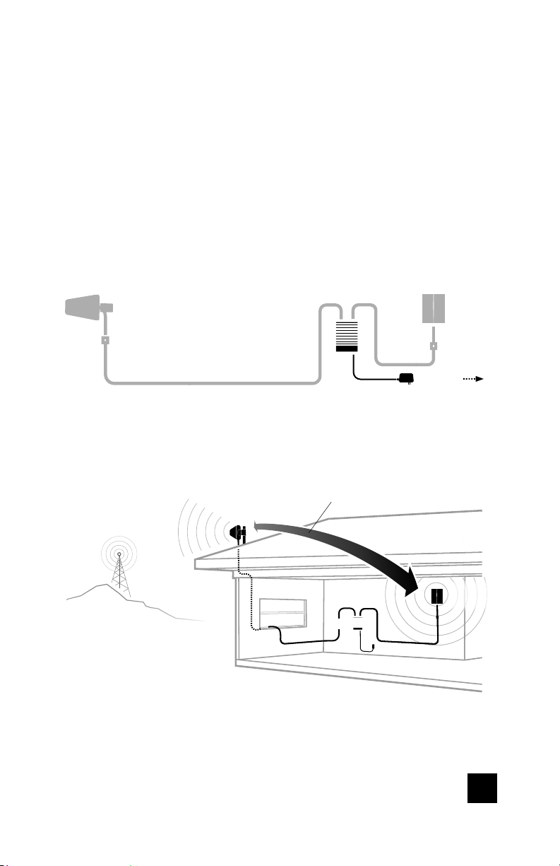
Plug the Power Supply into wall outlet then connect to the Booster.
Cell
Tower
Outside
Antenna
RG-11 Cable
Outside
Antenna
Booster
to power
50 FEET HORIZONTAL OR 20 FEET
VERTICAL DISTANCE
Booster
Power Supply
Inside
Antenna
Inside
Antenna
HOME COMPLETE CELL PHONE SIGNAL BOOSTER
7
Page 10
______
(STEP 4 cont.)
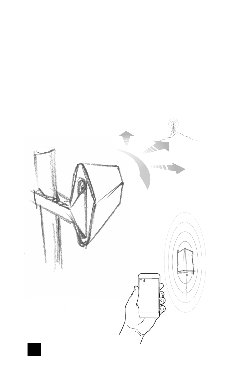
After powering up your system, you are now ready to optimize your system.
Rotate the Outside Antenna in 1/4 turn increments, after each turn, unplug
and reconnect the booster to power while observing the signal level on
your cell phone from the Inside Antenna’s projected area. Secure the
Outside Antenna in place, pointing in the direction that gives you the
strongest signal.
After each rotation, observe signal level
on your cell phone from the Inside Antenna’s
projected area
8
CELL PHONE SIGNAL BOOSTER HOME COMPLETE
Page 11

______
Measuring Booster
Performance
How To Get Signal Strength As A Number
iPhone®
iPhone®
iOS 11 - current
Dial *3001#12345#* then press Call.
1 Hold down power button until you see 'Slide to
Power O '.
2 Then release the power button.
3 Hold the Home button until your main screen appears.
If you want to check 3G/1x but your iPhone is picking up 4G/
LTE signal, go to Settings>Cellular>Cellular Data Options>Enable LTE>Select O .
After you system is set up, you can go back to the dots signal
by once again dialing *3001#12345#* then pressing call.
When the menu comes back up, tap “phone” in the top left
corner of your phone.
iOS 11 no longer displays the decibel (dBm) reading in ‘Field
Test Mode’. Tip: Using the bar indicator on your cell phone can
assist you in fi nding the strongest signal direction as well as
placing calls in di erent locations. For changes/updates on
this issue, periodically go to weboost.com/signalstrength.
Android™
Settings > About Phone > Status or Network > Signal Strength
or Network Type and Strength (exact options/wording
depends on phone model).
iPhone is a registered trademark of Apple Inc. Android is a trademark of Google Inc.
All Other Phones & Alternate Methods
Go to www.weboost.com/test-mode-instructions/
HOME COMPLETE CELL PHONE SIGNAL BOOSTER
9
Page 12
______
(MEASURING BOOSTER PERFORMANCE cont.)
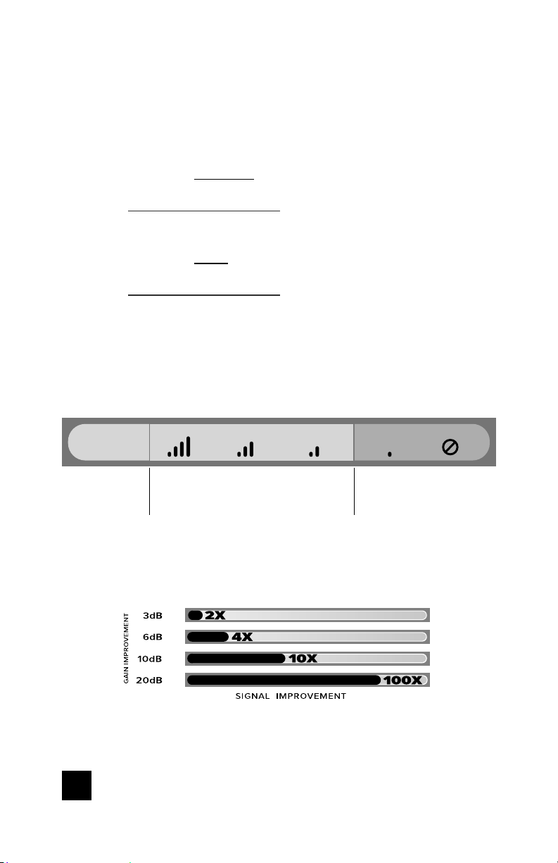
Signal Strength without Booster
Note here:
Signal Strength with Booster
Note here:
Compare Results
Having an accurate measurement of signal strength in decibels (dBm) is crucial when
installing your system. Decibels accurately measure the signal strength you are receiving.
SIGNAL
STRENGTH
3G/1x
4G/LT E
EXCELLENT GOOD FAIR POOR DEAD ZONE
-70dBm
-90dBm
-71 to -85dBm
-91 to -105dBm
-86 to -100dBm
-106 to -110dBm
-101 to -109dBm
-111 to -119dBm
-110dBm
-120dBm
DID YOU KNOW a signal increase of just 3dB is 2
times the power and signal amplifi cation!
10
CELL PHONE SIGNAL BOOSTER HOME COMPLETE
Page 13
______
Light Patterns
Solid Green
This indicates that your booster is
functioning properly and there are no
issues with installation.
Blinking Green, Then Red
Band has reduced gain. This indicates that one or more of the booster bands has reduced
power due to a feedback loop condition called oscillation. This is a built in safety feature
to prevent harmful interference with a nearby cell tower. If you are already experiencing
the desired signal boost, then no further adjustments are necessary. If you are not
experiencing the desired boost in coverage then refer to the Troubleshooting section.
Solid Red
Band has shutoff. This is due to a feedback loop condition called oscillation.
This is a built in safety feature that causes a band to shut off to prevent harmful
interference with a nearby cell tower. Refer to Troubleshooting section.
Blinking Green, Orange
Band has reduced gain. This indicates that one or more of the booster bands has reduced
power due to overload from nearby cell tower. This is a built in safety feature to
prevent harmful interference with a nearby cell tower. If you are already experiencing
the desired signal boost, then no further adjustments are necessary. If you are not
experiencing the desired boost in coverage then refer to the Troubleshooting section.
Solid Orange
Band has shutoff due to overload from nearby cell tower. Outside Antenna must be
adjusted. Refer to Troubleshooting section.
Light O
If the Signal Booster’s light is off, verify your power supply has power.
HOME COMPLETE CELL PHONE SIGNAL BOOSTER
11
Page 14
______
Troubleshooting
IF YOU ARE HAPPY WITH THE COVERAGE, THESE LIGHT ISSUES DON’T HAVE TO
BE RESOLVED. YOUR CARRIER’S BAND HAS NOT BEEN AFFECTED.
FIXING ANY RED LIGHT ISSUES
This involves Solid Red & Blinking Green/Red lights.
Verify Outside Antenna faces away from the Inside Antenna. Un-plug and re-
1
plug in power supply.
Verify the Inside Antenna is at least 18” from the Booster and pointed away
2
from the Booster. Unplug and re-plug in power supply.
Tighten all cable connections (be sure to handtighten only, do NOT use tools).
3
You may want to undo and redo the connection completely. Unplug and replug in power supply.
Increase the distance (horizontally or vertically) between the Outside and
4
Inside antenna. Add included cable if needed. Un-plug and re-plug in
power supply.
FIXING ANY ORANGE LIGHT ISSUES
This involves Solid Orange & Blinking Green/Orange lights.
Outside Antenna must be adjusted. Wait 10 seconds between adjustments for
the lights to reset. Rotate the Outside Antenna away from the strongest cellular
signal in small increments (45°) until the light turns green. Unplug and re-plug in
power supply.
NEED HELP?
12
support.weboost.com 866.294.1660
CELL PHONE SIGNAL BOOSTER HOME COMPLETE
Page 15

______
Antenna Kit Options
The following accessories are certifi ed by the FCC to be used with the
Home Complete Booster.
INSIDE FIXED
311135-40060
Panel w/60’ Wilson 400
311155-40060
Panel w/60’ Wilson 400
311135-582
Panel w/25’ RG-58
311155-0640
Panel w/40’ RG-6
301121-40010
Dome Antenna w/10’ Wilson 400
301151-0610
Dome Antenna w/10’ RG-6
309900-50N
2 Panel Antennas and a 50 Ohm 3-Way Splitter - 40’
Wilson400
309902-75F
2 Panel Antennas and a 75 Ohm 3-Way Splitter 20’ RG-6
309903-75F
3 Panel Antennas and three 75 Ohm 2-Way Splitter
- 35’ RG-11
309904-75F
1 Panel Antenna and a 75 Ohm 2-Way Splitter - 30’
RG-58
309905-50N
3 Panel Antennas and three 50 Ohm 2-Way Splitter
- 10’ RG-174
311155-1170
Panel w/70’ RG-11
301151-1110
Dome Antenna w/10’ RG-11
311245-100100
4G Directional Antenna 311245 With 100’ LMR 100
304412-40010
Dome w/10’ Wilson 400
304412-5810
Dome Antenna w/10’ RG-58
304419-1110
Dome w/10’ RG-11
304419-17410
Dome Antenna w/10’ RG-174
304419-0610
Dome Antenna w/10’ RG-6
311244-1160
4G Panel Antenna w/60’ RG-11
311244-0630
4G Panel Antenna w/30’ RG-6
OUTSIDE FIXED
314411-40075
Wide Band Directional Antenna With 75’ LMR 400
314411-5825
Wide Band Directional Antenna With 25’ RG-58
314475-0630
Wide Band Directional Antenna With 30’ RG-6
301111-0675
Yagi Antenna 301111 With 75’ RG-6
301111-5850
Yagi Antenna 301111 With 50’ RG-58
311203-40020
Omni Directional Antenna (311203) With 20’ LMR 400
314453-5825
Panel Antenna With 25’ RG-58
311203-5820
Omni Directional Antenna (311203) With 20’ RG-58
311201-0620
Omni Directional Antenna (311201) With 20’ RG-6
301126
Mini-Mag Antenna With 12.5’ RG-174
301111-11140
Yagi 301111 With 140’ RG-11
311201-1120
Omni Directional Antenna 311201 With 20’ RG-11
314453-40075
Panel Antenna With 75’ LMR 400
314473-0640
Panel Antenna With 40’ RG-6
311141-0620
Grey Brick w/20’ RG-6
311141-1120
Grey Panel With 20’ RG-11
314473-1175
Panel Antenna With 75’ RG-11
314475-1175
Wide Band Directional Antenna With 75’ RG-11
301111-400170
Yagi Antenna 301111 With 170’ LMR 400
304421-1120
Omni Consumer 304421 With 20’ RG-11
304421-17410
Omni Consumer 304421 With 10’ RG-174
304421-0610
Omni Consumer 304421 With 10’ RG-6
304421-5810
Omni Consumer 304421 With 10’ RG-58
304422-40020
Omni Enterprise 304422 With 20’ LMR 400
304422-5810
Omni Enterprise 304422 With 10’ RG-58
304422-1120
Omni Enterprise 304422 With 20’ RG-11
311245-1175
4G Directional Antenna 311245 With 75’ RG-11
311245-100100
4G Directional Antenna 311245 With 100’ LMR 100
311245-40075
4G Directional Antenna 311245 With 75’ LMR 400
311245-0630
4G Directional Antenna 311245 With 30’ RG-6
HOME COMPLETE CELL PHONE SIGNAL BOOSTER
13
Page 16
______
Safety Guidelines
To uphold compliance with network protection standards, all active cellular devices must
maintain at least six feet of separation distance from Inside Panel and Dome antennas.
Use only the power supply provided in this package. Use of a non-weBoost product may
damage your equipment.
The Signal Booster unit is designed for use in an indoor, temperature-controlled
environment (less than 100 degrees Fahrenheit). It is not intended for use in attics or similar
locations subject to temperatures in excess of that range.
RF Safety Warning: Any antenna used with this device must be located at least 8 inches
from all persons.
AWS Warning: The Outside Antenna must be installed no higher than 10 meters (31’9”)
above ground.
This is a CONSUMER device.
BEFORE USE, you MUST REGISTER THIS DEVICE with your wireless provider and have
your provider’s consent. Most wireless providers consent to the use of signal boosters.
Some providers may not consent to the use of this device on their network. If you are
unsure, contact your provider.
In Canada, BEFORE USE you must meet all requirements set out in ISED CPC-2-1-05.
You MUST operate this device with approved antennas and cables as specifi ed by the
manufacturer. Antennas MUST be installed at least 20 cm (8 inches) from (i.e., MUST
NOT be installed within 20 cm of) any person.
You MUST cease operating this device immediately if requested by the FCC (or ISED in
Canada) or licensed wireless service provider.
WARNING. E911 location information may not be provided or may be inaccurate for calls
served by using this device.
This device may be operated ONLY in a fi xed location (i.e..may operate in a fi xed location
only) for in-building use.
FOR MORE INFORMATION ON REQUIREMENTS SET OUT IN ISED CPC-2-1-05,
SEE BELOW:
http://www.ic.gc.ca/eic/site/smt-gst.nsf/eng/sf08942.html
FOR MORE INFORMATION ON REGISTERING YOUR SIGNAL BOOSTER WITH YOUR
WIRELESS PROVIDER, PLEASE SEE BELOW:
Sprint: http://www.sprint.com/legal/fcc_boosters.html
T-M obil e/Me troPCS: https://support.t-mobile.com/docs/DOC-9827
Verizon Wireless: http://www.verizonwireless.com/wcms/consumer/register-signal-booster.html
AT&T: https://securec45.securewebsession.com/attsignalbooster.com/
U.S. Cellular: http://www.uscellular.com/uscellular/support/fcc-booster-registration.jsp
14
CELL PHONE SIGNAL BOOSTER HOME COMPLETE
Page 17
Notes
NEED HELP?
HOME COMPLETE CELL PHONE SIGNAL BOOSTER
support.weboost.com 866.294.1660
15
Page 18
______
Specifi cations
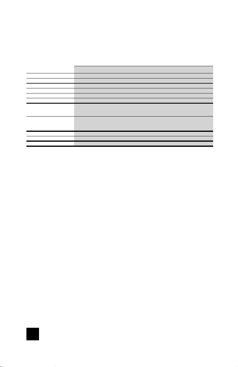
Model Number 460045
FCC ID
IC
Connectors F-Female
Antenna Impedance 75 Ohms
Frequency 698-716 MHz, 729-746 MHz, 777-787 MHz, 824-894 MHz, 1850-1995 MHz, 1710-1755/2110-2155 MHz
Power output for single cell
phone (Uplink) dBm
Power output for single cell
phone (Downlink) dBm
Noise Figure 5 dB nominal
Isolation > 110 dB
Power Requirements 12 VDC
The term “IC” before the radio certifi cation number only signifi es that Industry Canada technical specifi cations
were met.
Each Signal Booster is individually tested and factory set to ensure FCC compliance. The Signal Booster cannot
be adjusted without factory reprogramming or disabling the hardware. The Signal Booster will amplify, but not
alter incoming and outgoing signals in order to increase coverage of authorized frequency bands only. If the
Signal Booster is not in use for fi ve minutes, it will reduce gain until a signal is detected. If a detected signal is
too high in a frequency band, or if the Signal Booster detects an oscillation, the Signal Booster will automatically
turn the power o on that band. For a detected oscillation the Signal Booster will automatically resume normal
operation after a minimum of 1 minute. After 5 (fi ve) such automatic restarts, any problematic bands are
permanently shut o until the Signal Booster has been manually restarted by momentarily removing power from
the Signal Booster. Noise power, gain, and linearity are maintained by the Signal Booster’s microprocessor.
This device complies with Part 15 of FCC rules. Operation is subject to two conditions: (1) This device may not
cause harmful interference, and (2) this device must accept any interference received, including interference
that may cause undesired operation. Changes or modifications not expressly approved by weBoost could void
the authority to operate this equipment.
700 MHz
Band12/17
25.14 24.69 25.06 25.15 25.16
700 MHz
Band12/17
12.8 12.2 12.2 12.43 12.17
700 MHz
Band13
700 MHz
Band13
Home Complete
4726A-460045
PWO460045
800 MHz
Band 5
800 MHz
Band 5
™
1700 MHz
Band 4
2100 MHz
Band 4
1900 MHz
Band 25/2
1900 MHz
Band 25/2
16
CELL PHONE SIGNAL BOOSTER HOME COMPLETE
Page 19
2 YEAR WARRANTY
weBoost Signal Boosters are warranted for two (2) years against defects in
workmanship and/or materials. Warranty cases may be resolved by returning the
product directly to the reseller with a dated proof of purchase.
Signal Boosters may also be returned directly to the manufacturer at the
consumer’s expense, with a dated proof of purchase and a Returned Material
Authorization (RMA) number supplied by weoost. weBoost shall, at its option,
either repair or replace the product.
This warranty does not apply to any Signal Boosters determined by weBoost
to have been subjected to misuse, abuse, neglect, or mishandling that alters or
damages physical or electronic properties.
Replacement products may include refurbished weBoost products that have been
recertified to conform with product specifications.
RMA numbers may be obtained by contacting Customer Support
DISCLAIMER: The information provided by weBoost is believed to be complete
and accurate. However, no responsibility is assumed by weBoost for any business
or personal losses arising from its use, or for any infringements of patents or other
rights of third parties that may result from its use.
NEED HELP?
support.weboost.com 866.294.1660
HOME COMPLETE CELL PHONE SIGNAL BOOSTER
17
Page 20

3301 East Deseret Drive, St. George, UT
866.294.1660
Copyright © 2016 weBoost. All rights reserved.
weBoost products covered by U.S. patent(s) and pending application(s)
For patents go to: weboost.com/us/patents
www.weboost.com support.weboost.com
NOT AFFILIATED WITH WILSON ANTENNA
GDE000_RevFCC_01.21.19
 Loading...