

Page 1

WebEye 2.0 B101
Installation Guide
(v 2.3)
Page 2

FCC Compliance Statement
Caution : Any changes or modifications in construction of this device which are not expressly approved
the party responsible for compliance could void the user's authority to operate the equipment.
NOTE : This equipment has been tested and found to comply with the limits for a Class B digital device,
pursuant to part 15 of the FCC Rules. These limits are designed to provide reasonable protection against
harmful interference in a residential installation. This equipment generates, uses and can radiate radio
frequency energy and, if not installed and used in accordance with the instructions, may cause harmful
interference to radio communications, However, there is no guarantee th at interference will no t occur in a
particular installation. If this equipment does cause harmful interference to radio or television reception,
which can be determined by turning the equipment off and on, the user is encouraged to try to correct the
interference by one or more of the following measures:
Reorient or relocate the receiving antenna.
Increase the separation between the equipment and receiver.
Connect the equipment into an outlet on a circuit different from that to which the receiver is
connected.
Consult the dealer or an experienced radio/TV technician for help.
Caution
Change or Modifications not expressly approved by the party responsible for compliance could void the
users authority to operate the equipment
Warning
1. Danger of explosion if battery is incorrectly replaced. Replace only with the same or equivalent type.
2. Disposal of used batteries according to the general recommendations against the environmental
pollution.
3. Do not throw the batteries into a fire, and do not heat, short-circuit or attempt to disassemble the
batteries.
Page 3

Important Notice
1. WebEye is not weatherproof. Please note the environmental specifications that are included in the
manual. For outdoor usage, equip a weatherproof case to protect the WebEye from water, moisture, or
extreme temperature changes (higher or lower than the specifications noted below). The WebEye can be
cleaned by gently wiping with a clean dry cloth.
2. Be sure to use the DC adapter that is provided by Web Gate Inc. Connecting WebEye directly to an AC
current may cause damage to the WebEye.
3. Be cautious in handling WebEye. Physical shock such as dropping the unit may damage the WebEye
and void warranty.
4. The WebEye is made of aluminum. Be sure that it is fastened tightly during installation to avoid any
human injuries. Make sure to place away from the reach of children.
5. If WebEye does not operate properly, please contact your WebGate distributor for after sales service.
Unauthorized personnel are prohibited from disassembling the product. Disassembly will automatically
result in void of service warranty.
6. Camera surveillance laws may differ for each country and from province to province. Contact the local
region representative to avoid any violations and to apply for authorized purposes only.
Page 4

Contents
Introduction..................................................................................................................................6
1. What is WebEye 2.0 B101?.................................................................................................. 6
2. Supplied accessories .......................................................................................................... 7
3. Descriptions & Function...................................................................................................... 9
3.1. Using tapping screw......................................................................................................10
4. Installing & Connecting..................................................................................................... 11
4.1. Installing WebEye 2.0 setup program........................................................................... 11
4.2. System requirements of PC.......................................................................................... 11
4.3. Installig program ...........................................................................................................12
5. Connecting & Running ......................................................................................................15
5.1. Connecting WebEye 2.0 B101 to Network................................................................... 15
5.1.1. Connecting to PC directly......................................................................................15
5.1.2. Connecting to local Network..................................................................................16
5.2. Changing IP address & Login....................................................................................... 17
5.3. Setting Network.............................................................................................................18
5.3.1. When connected to Ethernet................................................................................. 18
5.3.2. When connected to xDSL......................................................................................18
5.3.3. When connected to PSTN..................................................................................... 19
5.3.4. Setting WRS(Dynamic IP registration) .................................................................. 19
5.4. Setting video.................................................................................................................21
5.5. Changing admin password & Registering user.............................................................22
5.6. Viewing image via browser........................................................................................... 23
6. Using Input / Output...........................................................................................................25
6.1. Connectinsg power.......................................................................................................26
6.1.1. Connecting DC power ...........................................................................................26
6.1.2. Connecting AC power............................................................................................ 27
6.2. Connecting & Setting serial port...................................................................................27
6.2.1. Connecting RS232.................................................................................................27
4
Page 5

6.2.2. Connecting RS422.................................................................................................27
6.2.3. Connecting RS485.................................................................................................27
6.3. Connecting & Setting sensor input ............................................................................... 28
6.3.1. Specification...........................................................................................................28
6.3.2. Diagram of sensor input ........................................................................................28
6.3.3. Connecting............................................................................................................. 28
6.3.4. Setting sensor input...............................................................................................29
6.4. Video input impedance (DIP) setting switch.................................................................30
6.5. Video input / output....................................................................................................... 30
6.6. Setting external device..................................................................................................30
Appendix ...................................................................................................................................32
#1. Specification................................................................................................................... 33
#2. How to recognize manufacturing date......................................................................... 35
5
Page 6

Introduction
1. What is WebEye 2.0 B101?
WebEye 2.0 B101 is a network video server solution with an integrated Internet server, image comp
ression device, flash memory, and many other features. No other hardware is necessary for use.
It relays video source from a CCTV camera to network and provides real time images over networks
and the Internet. Simply provide power and connect LAN cable and video cable to it.
Key features
Real-ti me monitoring through Network
4.5 MB Flash Memory for Homepage customization
Max. 100 simultaneous users support
RS 232 and RS 485/RS422 port support for PTZ control
Embedded Linux OS for excellent stability
Wavelet compression (30%~300% greater efficiency than JPEG) for higher refresh rate and
crisper images
4 external sensors support
S/W motion detection
Even t triggered E-Mail & FTP sending function
Easy setting
Dynamic IP (DHCP) support (xDSL, Cable modem, PSTN)
Two ways audio support
6
Page 7
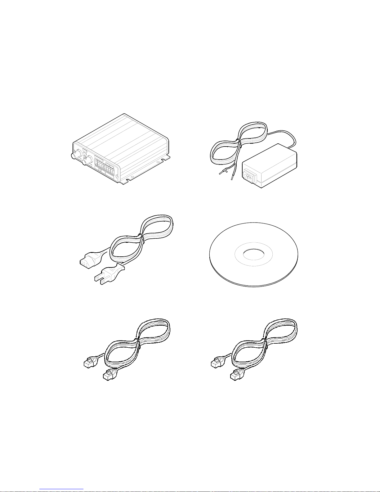
2. Supplied accessories
Unpack and check all the items as below.
1. B101 (1)
2. DC POWER SUPPL Y (1)
(FREE VOLTAGE)
3. AC POWER CORD (1)
4. CD-ROM (INCLUDING SOFTWARE &
MANUAL)(1)
5. ETHERNET CABLE (1, RED)
(UTP CATEGORY 5 CROSS CABLE)
6. ETHERNET CABLE (1, IVORY)
(UTP CATEGORY 5 DIRECT CABLE)
7
Page 8

7. PSTN CABLE (1)
8. TAPPING SCREW (4)
9. PLASTIC ANCHOR (4)
8
Page 9
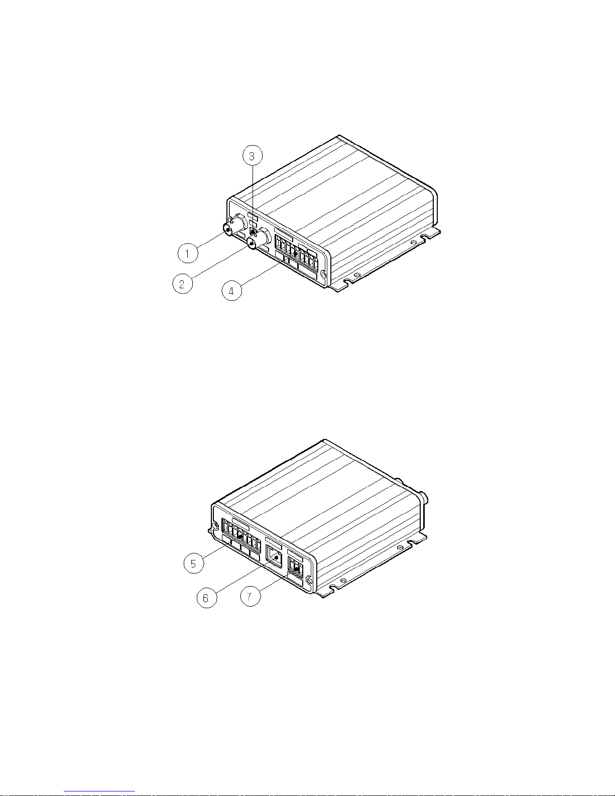
3. Descriptions & Function
(1) Video Input
(2) Video Output
(3) Impedance Switch
(4) Serial Communication
(5) Sensor Input
(6) Ethernet
(7) Power
9
Page 10
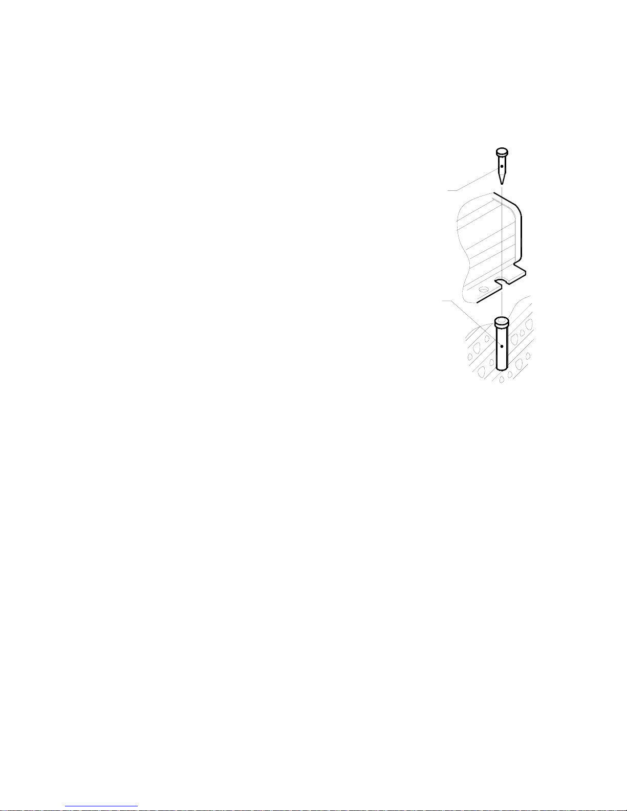
3.1. Using tapping screw
This is how to attach WebEye 2.0 B101 to wall or ceiling.
1) Make a hole (diameter: Φ6.5, depth: 30mm or above)
2) Insert the supplied plastic anchor into the hole.
PLASTIC
ANCHOR
TAPPING
SCREW
3) Fix WebEye 2.0 B101 with tapping screw.
10
Page 11

4. Installing & Connecting
4.1. Installing WebEye 2.0 setup program
Within the supplied CD-ROM DISC, there are “WebEye 2.0 B101 User ’s Guide” and WebEye 2.0 setup
programs for using WebEye B101 2.0.
4.2. System requirements of PC
Minimal Recommended
CPU Intel Pentium III 600Mhz Intel Pentium IV 1.6Ghz or above
Memory (RAM) 128MB 512MB
VGA 16MB 64MB
Resolution 1024ⅹ768 1280ⅹ1024
HDD 5MB 1GB or higher
OS Windows 98/SE/ME/2K/XP, LINUX,
MAC OS 10.2.3 or above
Windows 2000 SP4 or above / XP SP2
or above
Browser Internet Explorer 5.5 or above
Netscape 7.0 or above
Mozilla 1.2.1 or above
Safrai 1.0 or above
Internet Explorer 6.0 SP2 or above
Others WespController
Java Plug-in 1.4.x
W espController
Java Plug-in 1.5.x
DirectX 8.1 or higher
WebEye 2.0 is optimized on the based of Windows 98 / SE / ME / 2000 (SP4 or above) / XP (SP2 or
above) and Internet Explorer 6.0 or above (SP2 or ab ove).
When using Netscape, version 7.x or above is required and Java Plug-in 1.5.x or above should be installed.
When using Linux, Mozilla 1.2.1 or above / Netscape 7.x or above is required and Java Plug-in 1.5.x or
above should be installed.
When using Mac OS, Safari 1.0 or above is required and Java Plug-in 1.5.x or above should be installed.
Java Plug-in 1.5.x can be installed in Mac OS X 10.2.3 or the newest version.
When using basic video driver that Microsoft supports, DirectX may cause abnormal display or low
performance. In this case, do not use DirectX or install the newest video driver with searching for website.
11
Page 12
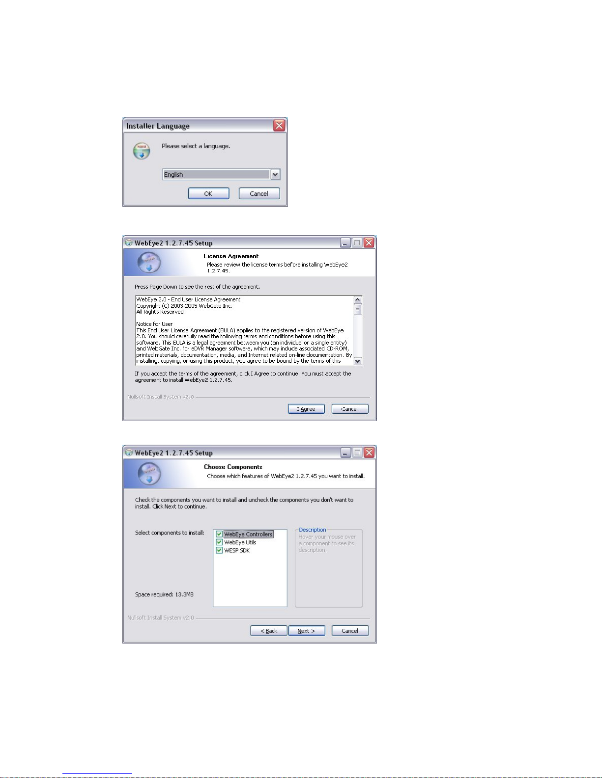
4.3. Installig program
(1) Run “WebEye 2 Setup v.1.x.x.x.exe” file in WebEye 2.0 Seup CD.
(2) Select a language and click the “OK” button.
(3) Press the “I Agree” button.
(4) In order to use all functions of WebEye 2.0, select “WebEye Controllers”, “WebEye Utills”, and
“WESP SDK”
12
Page 13
WebEye Controllers
To istall necessary program for aeecssing WebEye 2.0 and monitoring its image.
WebEye Utils
To install WebEye2 Configuration Tool (Setting), WebEye2 MiniPlayer (Replaying the quick
recorded file), and WebEye2 OnetimePW (Creating one time password).
WESP SDK
To install WESP library file that is used in WebEye 2.0.
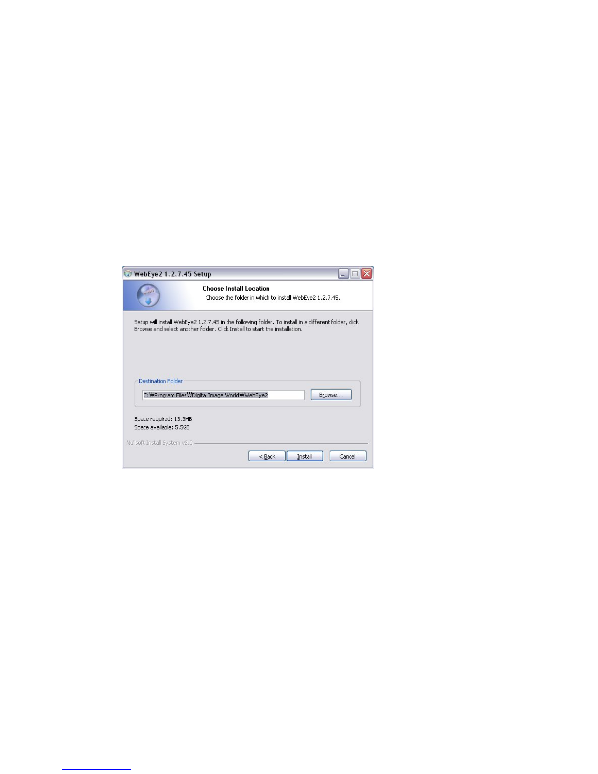
(5) Select a folder to install and press the “Install” button.
13
Page 14
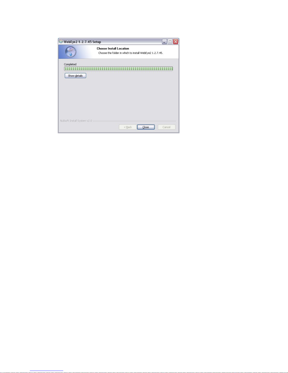
(6) Complete to install with pressing the “Close” button.
Check whether all three programs are installed.
- WebEye 2 Configuration Tool
- WebEye 2 MiniPlayer
- WebEye 2 OnetimePW
14
Page 15
5. Connecting & Running
5.1. Connecting WebEye 2.0 B101 to Network
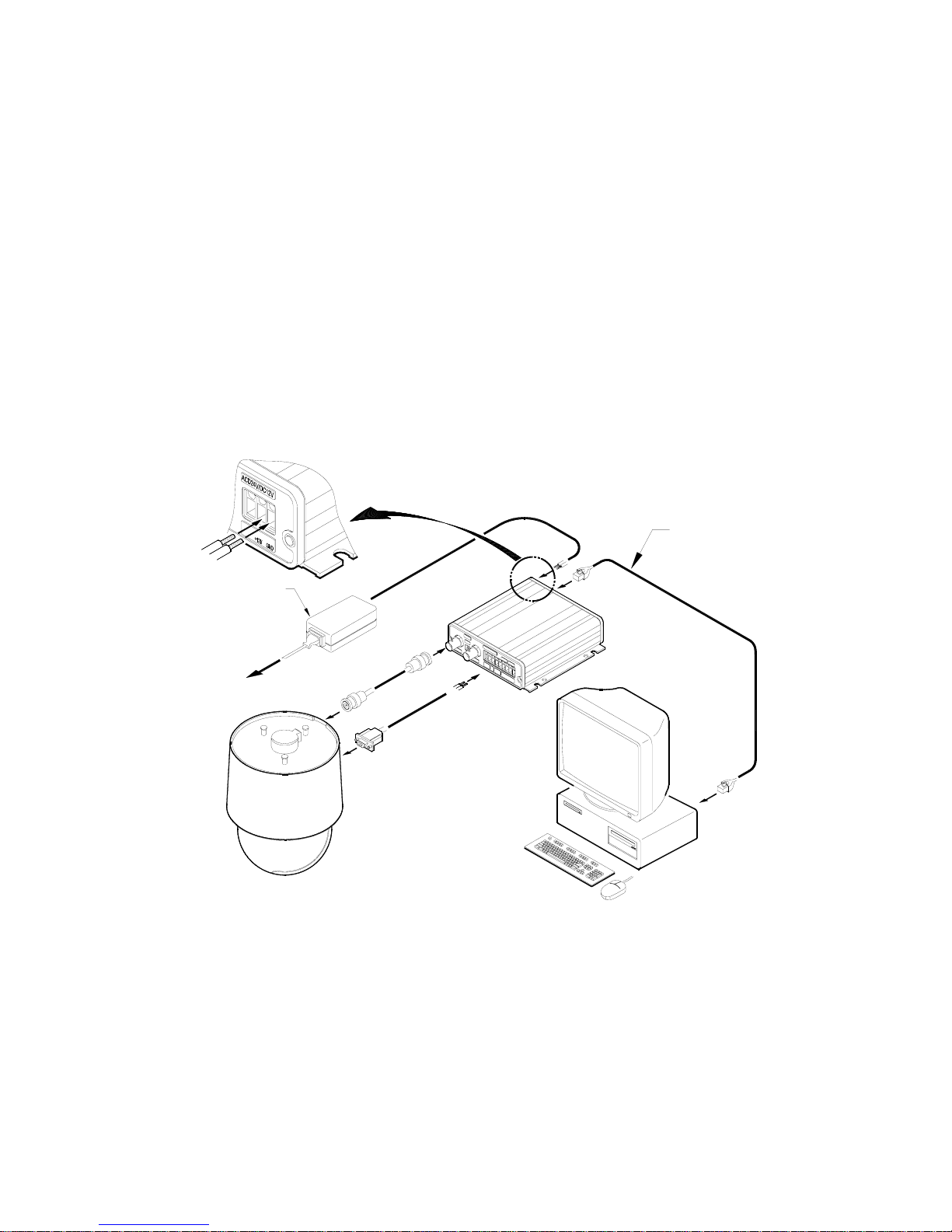
Connect WebEye 2.0 B101 to PC directly with cross cable or connect WebEye 2.0 B101 to local Network
with direct cable.
5.1.1. Connecting to PC directly
(1) Connect WebEye 2.0 B101 to client’s PC with cross cable.
(2) Connect an external camera to WebEye 2.0 B101’s vide o i np ut wit h B NC cable.
(3) Connect the supplied AC adaptor to WebEye 2.0 B101.
TO AC OUTLET
POWER SUPPLY
(SUPPLIED)
ETHERNET
(SUPPLIED)
CROSS OVER CABLE
15
Page 16
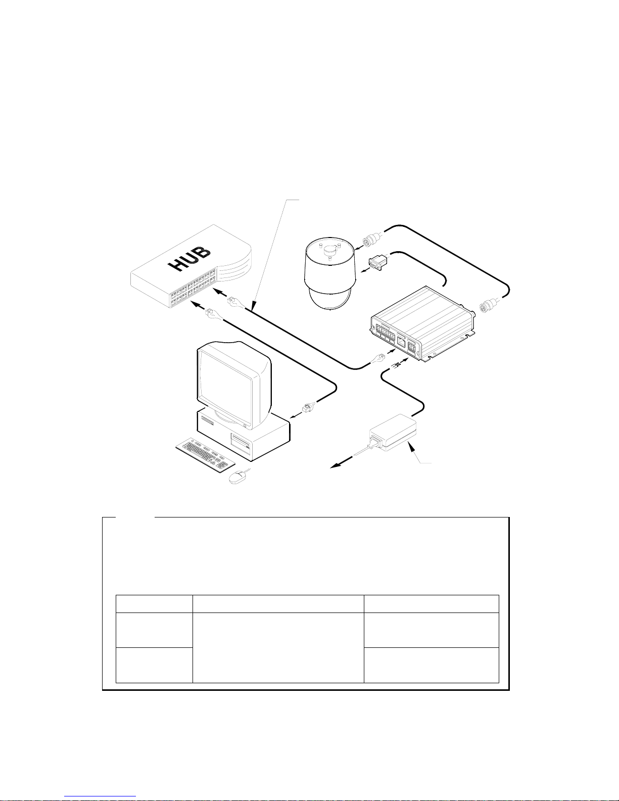
5.1.2. Connecting to local Network
(1) Connect WebEye 2.0 B101 to HUB with direct cable.
(2) Connect an external camera to WebEye 2.0 B101’s vide o i np ut wit h B NC cable.
(3) Connect the supplied AC adaptor to WebEye 2.0 B101.
POWER SUPPLY
(SUPPLIED)
ETHERNET
(SUPPLIED)
DIRECT CABLE
TO AC OUTLET
<Note>
1. To prevent WebEye 2.0 B101’s damage, you should connect power cable after connecting Ethernet
cable.
2. Ethernet cable should be pushed and connected, If not, noise may be occurred.
3. Check the LED of WebEye 2.0 B101 after supplying power.
Network status Yellow LED Green LED
Connected
It is on for the first 1-2 seconds,
and it blinks once per second.
Disconnected
It is on for the first 4-5 seconds and it
goes off. Then it keeps blinking fastly.
It is on for the first 1-2 seconds,
and it blinks once per 2 seconds.
16
Page 17
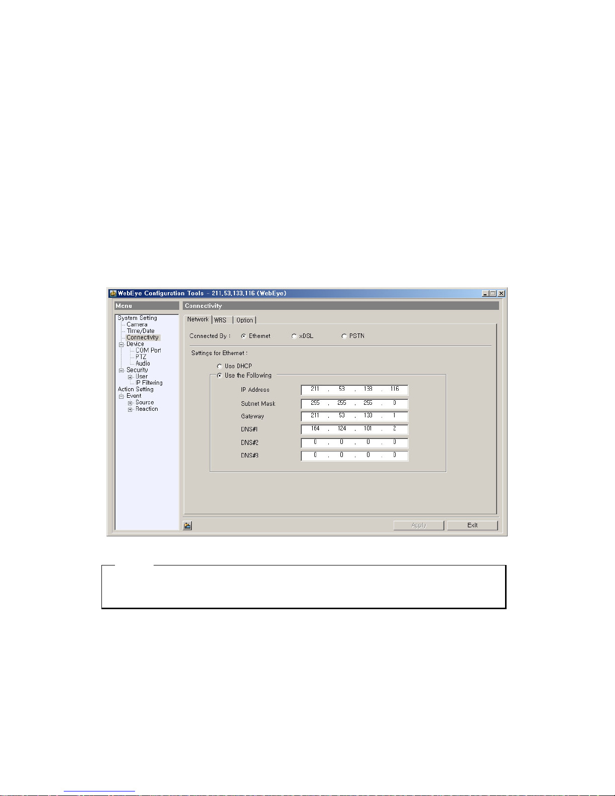
5.2. Changing IP address & Login
After connecting WebEye 2.0 B101 to Network, its IP address should be changed according to each
Network environment to access WebEye 2.0 B101 normally.
(1) Run WebEye 2. Configuration Tool in PC.
(2) Every WebEye 2.0, which is connected to local Network, is displayed in “Local Area Units”.
(3) Register WebEye at “My Units”.
(4) Move to “Network” tab in “Connectivity” menu.
(5) Set IP Address, Subnet Mask, and DNS.
(6) Press the “Apply” button after setting.
<Note>
1. The default password of admin is “admin”.
17
Page 18

5.3. Setting Network
5.3.1. When connected to Ethernet
When WebEye 2.0 B101 is connected to Ethernet, set IP ad dress and another information in “Network”
tab.
Setting IP address manually
(1) Enter IP address.
(2) Enter subnet mask.
(3) Enter gateway.
(4) Enter DNS.
(5) Enter the “Apply” button
Setting IP address automatically
(1) Check “DHCP Enable”.
(2) Press the “Apply” button.
<Note>
1. If checking “DHCP Enable”, WRS should be set.
2. When using cable modem or xDSL (automatic access modem), set it as “Ethernet” type.
5.3.2. When connected to xDSL
When WebEye 2.0 B101 is connected to xDSL line, set as follows then connect to xDSL line.
(1) Select “xDSL” type in “Network” tab.
(2) Enter ID and password for connecting to xDSL.
(3) Press the “Apply” button.
<Note>
1. xDSL has three kinds; ADSL, HDSL, and VDSL It can be used, when using PPPoE protocol.
2. When setting Network with xDSL, WRS menu should be set. (except using static IP)
3. If Network is set as xDSL type, Ethernet can’t be connected.
4. User’s ID and password is supplied from each xDSL ISP.
5. When using automatic connecting modem, even though Network line is xDSL type, a value should be
set as Ethernet.
18
Page 19
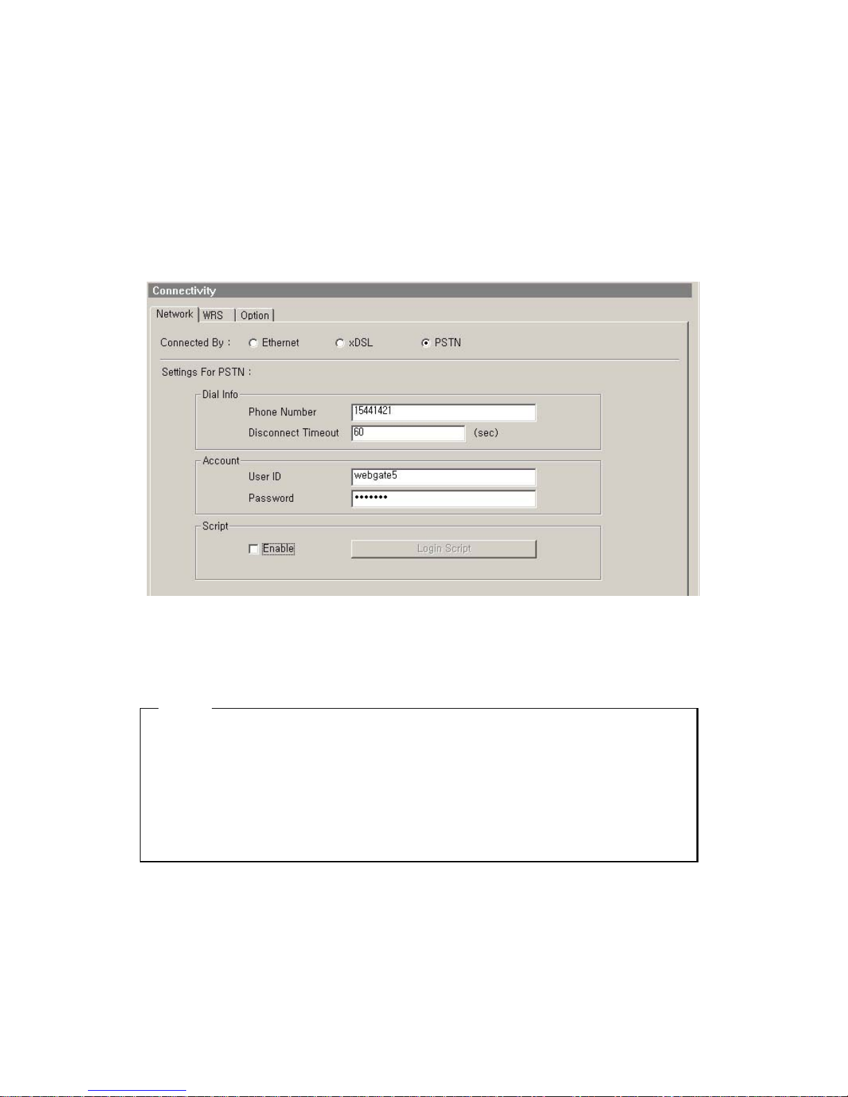
5.3.3. When connected to PSTN
When WebEye 2.0 B101 is connected to PSTN line, Dial In/Out function is possible.
When sending event or periodic E-Mail, FTP, Dial Out function runs. When accessing WebEye 2.0 B101
that is connected through PSTN, Dial In function runs.
5.3.3.1. Setting dial out
(1) Select PSTN.
(2) Enter PSTN ISP phone number.
(3) Enter ISP User ID and Password, then press the “Apply” button.
<Note>
1. WebEye 2.0 B101 supports PPP among PSTN types.
2. User’s ID and password is supplied from each PSTN ISP.
3. For more information about login script, inquire of PSTN ISP.
4. In orde to use PSTN modem, set the related values of modem.
5. When accessing via Dial In, access ID and Password, which are set in FTP User Accounts, should be
entered.
5.3.4. Setting WRS(Dynamic IP registration)
If WebEye 2.0 B101 is installed on a network of dynamic IP address (floating IP address), administrator
should register the WebEye 2.0 B101 on dynamic IP registration server to give common users simple
connectivity. If not, no one can access the WebEye 2.0 B101 through Web browser. It is because that no
19
Page 20

one knows IP address which one can access the WebEye 2.0 B101 with.
To solve the problem, WebGate runs WRS(Dynamic IP Registration Sever).
(1) Select a registration interval. (1 minute~24 hours)
(2) Enter server address. (default value : 210.116.114.37)
(3) Enter access token.
(4) Use WebEye server name as group ID.
(5) Press the “Apply” button.
<Note>
1. WebEye 2.0 should be set at WRS in following cases.
- When using DHCP in Ethernet
- When using xDSL (except using static IP)
In order to check after registering at WRS, refer to WebEye2 Configuration Tool or “Registered
WebEye list” at WebGate’s web site.
<Note>
If checking “Add Public List”, WebEye 2.0 is registered at public list and it can be searched.
URL address of registered WebEye list
http://www.webgateinc.com/webeyetable/view-webeye.php
20
Page 21
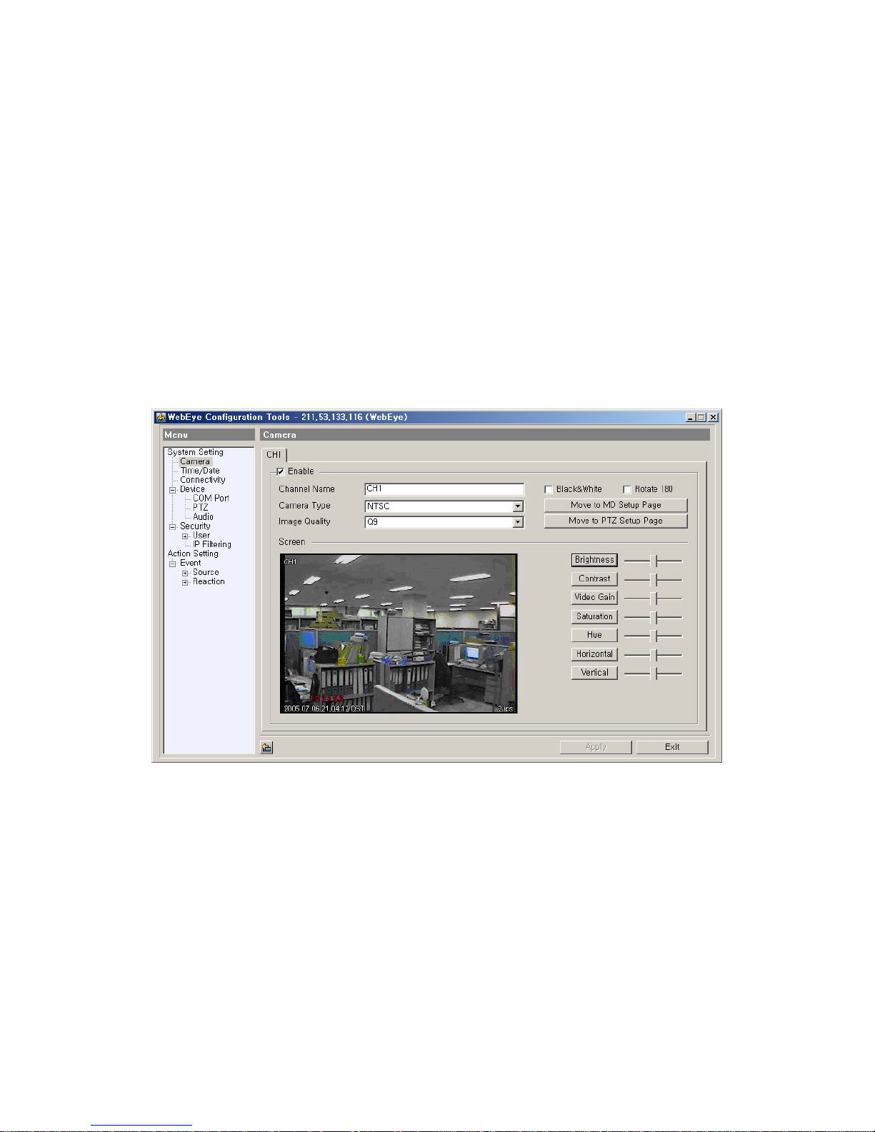
5.4. Setting video
It is to set video input channel.
(1) Select video channel to set.
(2) Check “Enable”.
(3) Select video type (NTSC/PAL). (If video type is changed, WebEye should be rebooted.)
(4) When camera is installed reversely, check “Rotation 180’.
(5) Select image quality. (Q0~Q9)
(6) Press the “Apply” button after setting channel.
(7) Possible to move MD and PTZ setting pages with the “Move to MD Setup Page” and “Move to
PTZ Setup Page” buttons.
21
Page 22
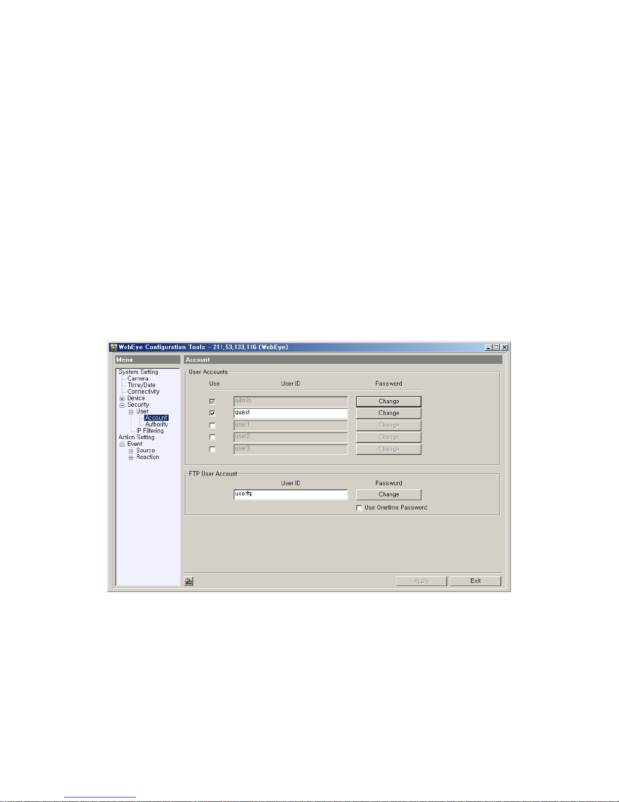
5.5. Changing admin password & Registering user
Administrator’s ID is fixed as “admin”, and the default admin password of WebEye 2.0 B101 is “admin”.
The ID can’t be changed, but only passwo r d can be chan ged.
(1) Press the “Change” button.
(2) When the related dialogue is shown, enter old password & new password and press the “OK”
button.
(3) Press the “Apply” button.
User account can be registered upto 4 users. Default user accounts are guest, user1, user2, and user3.
(1) Check the “Use” for using account.
(2) Enter user ID.
(3) Set password after pressing the “Change” button.
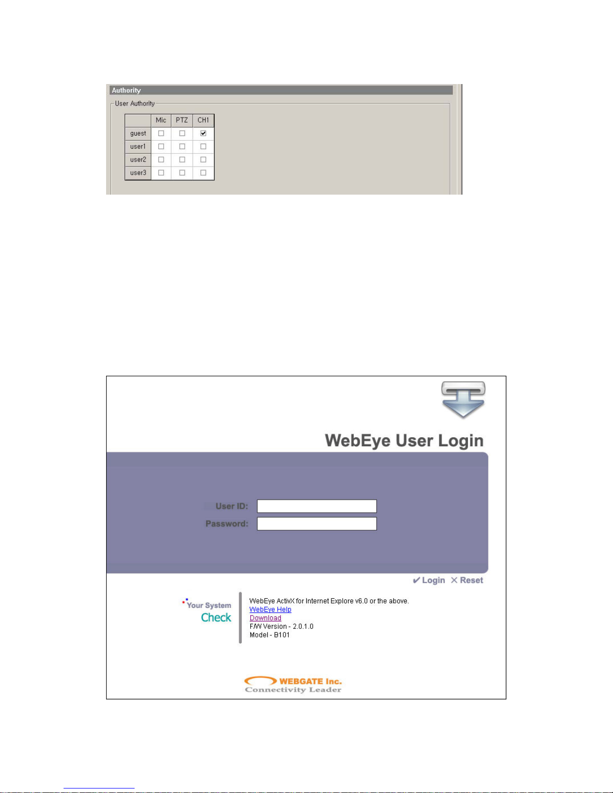
(4) Mic, PTZ, or Channel use authorities can be set in “Security Æ User Æ Authority” menu.
(5) Press the “Apply” button.
22
Page 23
5.6. Viewing image via browser
After setting Network and Video tabs, image of WebEye can be viewed via web browser.
(1) Run web browser at PC.
(2) Enter IP address of WebEye 2.0 to access.
(3) If WebEye is accessed, login page will show.
(4) Enter user ID and password, and clicking the “Login” button.
(5) When login is normal, single viewer page will show and channel 1 will be displayed.
23
Page 24
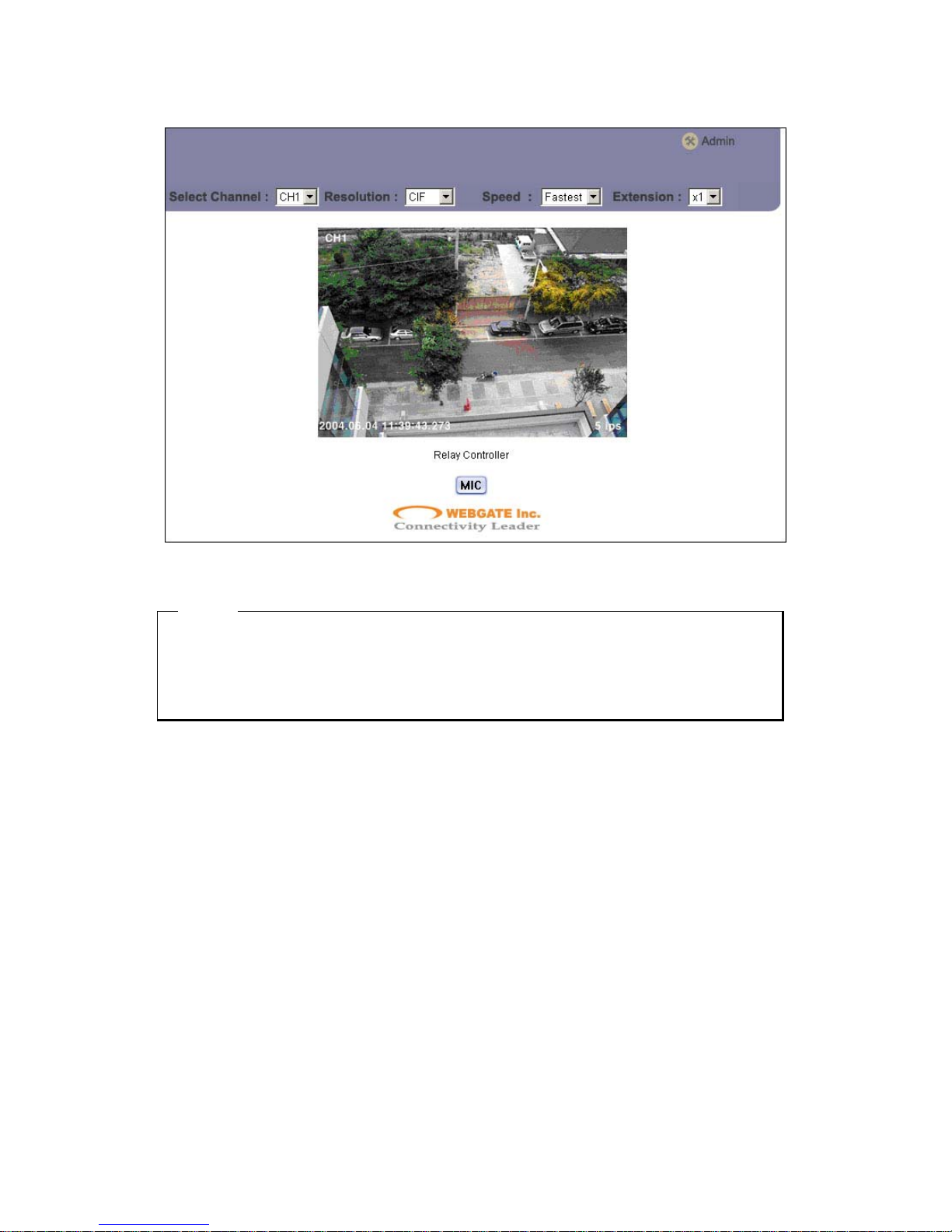
<Note>
When accessinf WebEye 2.0 web page for the first time without installing WebEye Setup
v1.2.x.x.exe file, an installation message for certifying and running image will be shown at login
step. For using WebEYe 2.0 B101 normally, the control prog ram should be installed.
24
Page 25
6. Using Input / Output
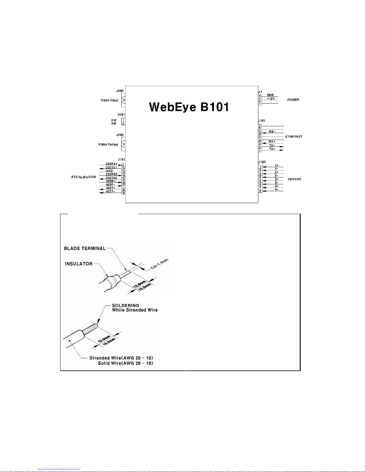
The electrical diagram of WebEye 2.0 B101 is as below.
<Note> T rimming Wire
When connecting a wire to a terminal block, follow the instructions below. Note the different types of
wire that can be used. (1) is recommended.
(1) Compress the cable with the appointed Blade
terminal. Use insulator against electric shock.
(2) Stranded Wire: Peel off the wiring cover
12~15mm and solder it. Wire gage should be
AWG 28 ~ 18.
(3) Solid Wire: Peel off the wiring cover
12~15mm and solder it. Wire gage should be
AWG 28 ~ 16.
25
Page 26
6.1. Connectinsg power
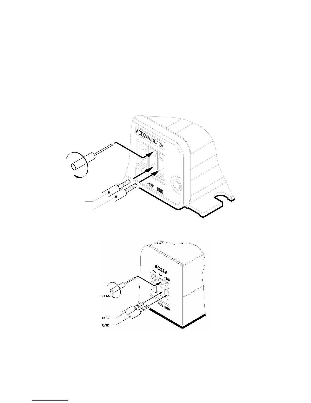
When supplying power to WebEye 2.0 B101, you should certainly do that after connecting WebEye 2.0
B101 to power cable to WebEye 2.0 B101. Don’t connect power cable to WebEye B101 with supplied
power.
6.1.1. Connecting DC power
6.1.1.1. Diagram
+12V
GND
FIXING
6.1.1.2. Connecting
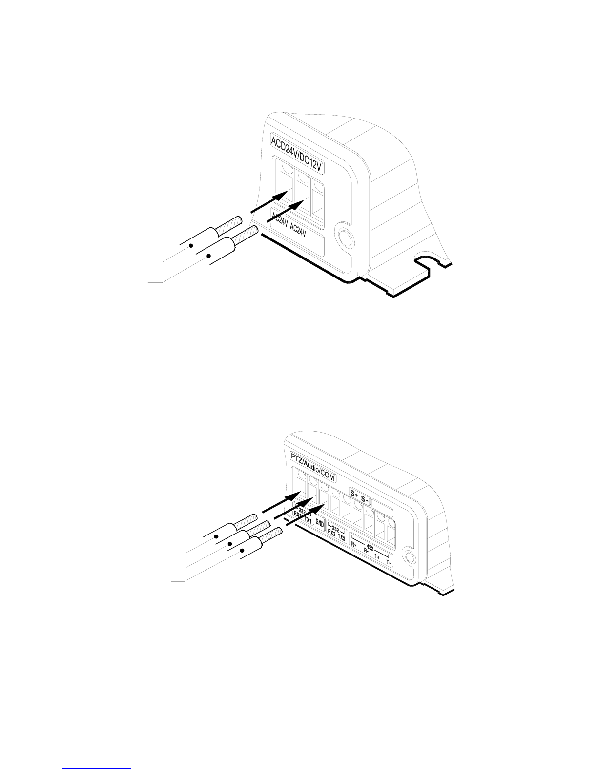
When connecting to DC power, insert cables to 2, 3 pins (+12V, GND) and screw clockwise.
26
Page 27
6.1.2. Connecting AC power
AC24V
AC24V
6.2. Connecting & Setting serial port
6.2.1. Connecting RS232
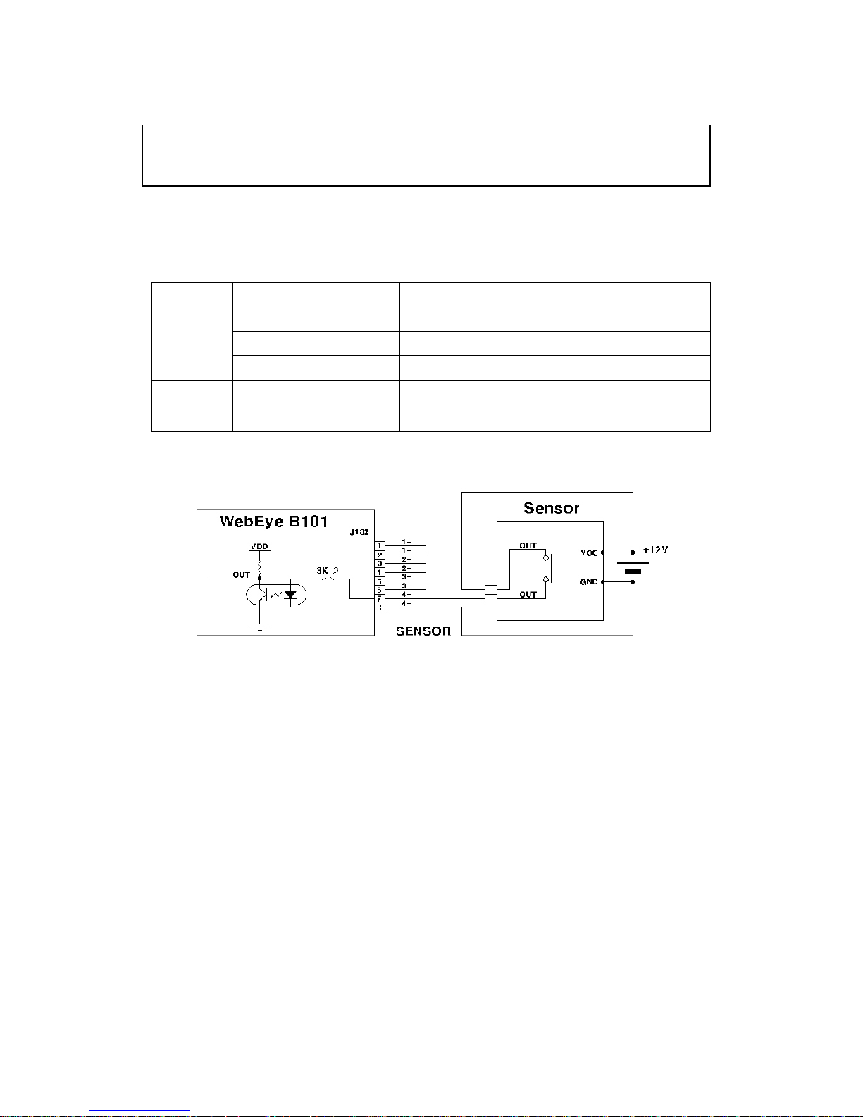
Within WebEye B101, there are four RS232 communication terminals; RX1, TX1, RX2, and TX2.
When connecting RX1, and TX1, connect each pin to No. 1~3 hole. And when connecting, RX2,
TX2, connect each pin to No. 3~5 hole.
RX1
TX1
GND
6.2.2. Connecting RS422
Connect each pin to No. 6~9(R+, R-, T+, T-) hole.
6.2.3. Connecting RS485
Connect each pin to No. 6~7(S+, S-) hole.
27
Page 28
<Note>
1. When connecting to RS485 or RS422, you should connect the ground among devices.
If not, it may cause abnormal operation or damage on device.
6.3. Connecting & Setting sensor input
6.3.1. Specification
In order to run sensor input of WebEye 2.0 B101 normally, the following conditions are required.
Input Ch. 4Ch. Photo coupler differential inputs
Input type NO / NC
Supported sensor Dry contact
Spec.
Connecting Connecting the trimmed wire to terminal block
Available input pulse range Min. 500ms
Performance
Output current Typical DC 12mA
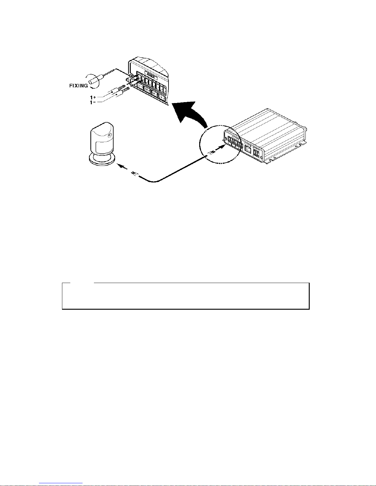
6.3.2. Diagram of sensor input
6.3.3. Connecting
When connecting sensor 1, inset cables to 1, 2 pins (1+, 1-) as followings. Connect sensor 2~4 equally.
28
Page 29
6.3.4. Setting sensor input
Set a sensor type.
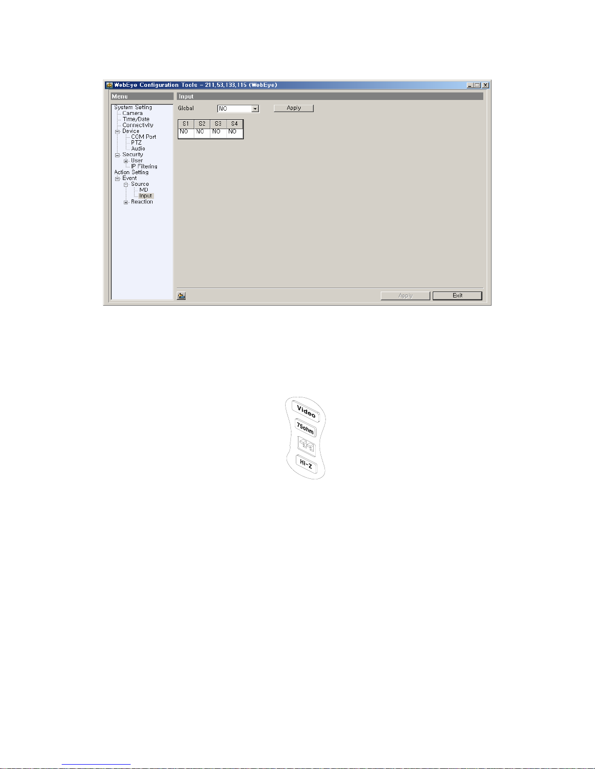
(1) Run “WebEye 2 CofigStation Tool”
(2) Log in the WebEye 2.0, and click “Event Æ Source Æ Input” menu.
(3) Possible to set sensor by sensor. When setting as same value, use “Global” menu and click the
“Apply” button.
(4) Press the “Apply” button after setting.
<Note>
NO : Normal Open Type (It means circuit is disconnected at normal case.)
NC : Normal Close Type ((It means circuit is connected at normal case)
29
Page 30
6.4. Video input impedance (DIP) setting switch
Configure the impedance of video input. If selecting 75ohm, impedance will be set as 75ohm. And
if selecting Hi-z, impedance will be set as no limit.
6.5. Video input / output
Within WebEye 2.0 B101, there are video input and output terminal. To view image with CCTV
monitor, input IMPEDANCE should be configured. Because Video input and output of WebEye 2.0
B101 is linked, any one between WebEye 2.0 B101 and CCTV monitor should be configured as
75ohm impedance.
6.6. Setting external device
After connecting device to serial port, set a value according to device.
(1) Run “WebEye 2 Configuration Tool”.
(2) Log in WebEye2.0 B01 and click the “Device” tab.
(3) Set the related serial port.
30
Page 31
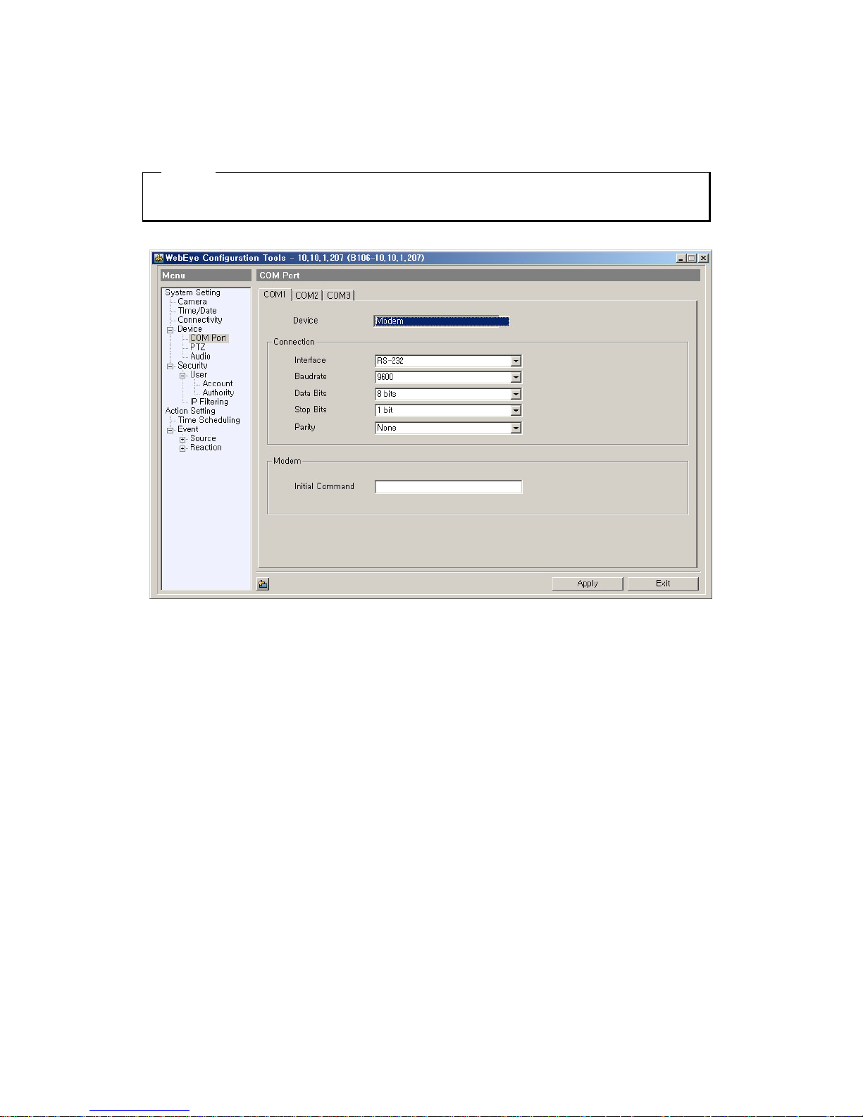
(4) Press the “Apply” button after setting.
<Note>
When connecting modem, set “Modem Initial Command”.
31
Page 32

Appendix
32
Page 33

#1. Specification
General
CPU
32bit RISC Embedded Processor
8MB
Flash memory
Main memory
16MB
OS
Embedded Linux
Video channel
NTSC or PAL video format are supported
1Ch. analog video inputs via BNC connector
Image compression
Algorithm
Wavelet
Resolution
720x486, 720x243, 360x243, 180x121, 90x60 (NTSC)
720x576, 720x288, 360x288, 180x144, 90x72 (PAL)
10:1 ~200:1
Image compression rate
Max. 30fps (NTSC, on 360x243)
Image transfer rate
Max. 25fps (PAL, on 360x288)
Network
Internet Explorer 5.5 or above
Netscape 7.0 or above
Browser
Mozilla 1.2.1 or above
Safari 1.0 or above
TCP/IP, ARP, RARP, ICMP, DHCP, FTP, SMTP, PPP,
PPPoE
Protocol
Connector
10-Base T Ethernet (RJ-45)
Management & S/W upgrade
Remote system setting over the Network
Security
User or Administrator Authenticantion
IP-Filtering (Secure Mode)
Max. simultaneous users
Max. 100 users
33
Page 34

Environment
-10C ~ +45C
Operation temperature
Storage temperature
-25C ~ +70C
Operation humidity
30% ~ 80% R.H (free of condensation)
Storage humidity
93% R.H below (free of condensation)
Additional function & Input/Output
Image quality Control (10 Levels)
Additional function
Periodical sending the images through E-Mail, FTP
4.5 MB fresh memory for homepage customization
Sending e-mail automatically
Alarm
Sending the images files through FTP automatically
RS232, RS485/RS422
PTZ control
4 Ch, TYPICAL 12mA (When using Dry Contact)
Sensor input
Others
Power (Applied adaptor)
Input: AC 100~240V, 50~60 Hz, 0.3A
Output: DC 12V, 1.5A
Consumption electricity
350mA (DC 12V)
170mA (AC 2 4V)
Consumption voltage
4.2W (DC 12V)
4.1W (AC 24V)
34
Page 35

#2. How to recognize manufacturing date
The manufacturing date by Webgate can be recognized by S/N(Serial Number)
attached at the each product.
S/N : Serial Number
Management number for each Webgate product to combine twelve alphabet character and
digit including model name, manufacturing year/month/week
You can see serial number by looking at the bottom of product attached label and
system info of Configuration Tool.
Serial Number Format
□ □ □ □ □ □ □ □ □ □ □ □
Year/Month
Webgate No. Webgate No.
Model Name No.
(1) 1~2 digits : Identify Model name of product
(2) 3~8, 8~12 digits : Webgate internal number
(3) 5~6 digits : Manufacturing year
(4) 7 digits: Manufacturing month
Please see the below table for manufacturing month.
Jan Feb Mar Apr May Jun Jul Aug Sep Oct Nov Dec
1 2 3 4 5 6 7 8 9 A B C
The example of verifying manufacturing date using serial number
The below S/N can be verified as following as:
『 D60507B22051 』
(1) “D6” means “DS1600Q” product
(2) “07B” means that it was manufactured on November of 2007
35
Page 36

WEBGATE Inc.
6F, Hanlim Venture Town Bldg., 689-6, Geumjeong-dong, Gunpo-si,
Gyeonggi-do, Korea (43 5-862)
Tel : (82-31) 428-9300
Fax : (82-31) 428-3955
[email protected]
www.webgateinc.com
 Loading...