

Page 1

Installation & User’s Guide
VS04S
(v 1.3)
Page 2

Caution
As this equipment undergoes EMC registration and is suitable for business purpose, distributors and users
are aware of this point. This equipment is suitable except home.
FCC Compliance Statement
Caution : Any changes or modifications in construction of this device which are not expressly approved
the party responsible for compliance could void the user's authority to operate the equipment.
OTE : This equipment has been tested and found to comply with the limits for a Class A digital
device, pursuant to part 15 of the FCC Rules. These limits are designed to provide reasonable protection
against harmful interference when the equipment is operated in a commercial environment. This
equipment generates, uses, and can radiate radio frequency energy and, if not installed and used in
accordance with the instruction manual, may cause harmful interference to radio communications,
Operation of this equipment in a residential area is likely to cause harmful interference in which case
the user will be required to correct the interference at his own expense.
Warning
This is a class A product. In a domestic environment this product may cause radio interference in which
case the user may be required to take adequate measures
Warning
1. In case of changing built-in lithum battery, it should be replaced as same or kindred one to prevent a
danger of explosion. Since old batteries could be a factor of environment contamination, be cautios to
treat them.
2. Do not throw the batteries to fire or heating. Neither short circuiut or disassembly is prohibited.
3. Do not charge the batteries provided with Remote Controller
Page 3

Important otice
1. Do not place heavy objects on the top of the product.
2. Product is for indoor use. It is not weatherproof. Use product with referring to its environmental
specifications (Temperature & Humidity). To clean the product, gently wipe the outside with a clean dry
cloth.
3. Product uses AC power of 110V ~ 240V. Be cautious not to cause electric damages to product.
4. Be careful not to drop the product. Physical shocks may harm the product including internal HDD. In
addition, be sure the product is secured after installation.
5. Product is made of metal. Therefore you can hurt human beings if you throw it to them or hit on them.
When installing product, be cautious to locate on safe places where children are unreachable.
6. If Product does not operate properly, please contact the closest WEBGATE distributor for after sales
service. Tampering or disassembling the product will void the warranty.
7. Security surveillance laws may differ for each country. Therefore, please contact the local region first
to avoid any surveillance law violations.
The content of this manual can differ according to firmware or Software upgrading, and the standard and
appearance of products may be changed for the improvement of quality without an advance notice.
Page 4

4
Contents
Installation Guide ......................................................................................................................... 7
Overview ........................................................................................................................................ 7
1. Introduction ............................................................................................................................ 7
2. Main features .......................................................................................................................... 8
3. Supplied accessories ................................................................................................................ 9
4. Description & Function ......................................................................................................... 10
Installation and Connection .......................................................................................................... 12
5. Connecting & Running ......................................................................................................... 12
5.1. Power connection and operation ....................................................................................... 12
5.2. Connect in Private mode .................................................................................................. 12
5.3. Connecting in Public mode ............................................................................................... 14
6. Using Control Center ............................................................................................................ 15
6.1. Starting ........................................................................................................................... 15
6.1.1. PC system requirements for running Control Center .................................................... 15
6.2. Installing Control Center .................................................................................................. 15
6.3. Log-In ............................................................................................................................ 17
6.4. Monitor .......................................................................................................................... 18
6.5. Configuration Tool .......................................................................................................... 19
6.6. Playback ......................................................................................................................... 21
6.6.1. Open Back-up file and Unit ....................................................................................... 21
User’s Guide ............................................................................................................................... 22
7. Description............................................................................................................................ 22
7.1. Rear Part ......................................................................................................................... 22
7.2. Front Part ........................................................................................................................ 22
7.3. Installation summary........................................................................................................ 23
8. VS04S Configuration .......................................................................................................... 24
8.1. Log in Configuration Tool ................................................................................................ 24
Page 5

5
8.2. Interface ......................................................................................................................... 25
8.2.1. Site Tree .................................................................................................................. 25
8.2.2. Menu....................................................................................................................... 25
8.2.3. Configuration page ................................................................................................... 26
8.2.3.1. System Setting .................................................................................................. 26
8.2.3.2. IP Camera ........................................................................................................ 27
8.2.3.2.1. IP Camera Configuration ......................................................................................... 27
8.2.4. Time/Date ................................................................................................................ 31
8.2.4.1. Setting Date & Time .......................................................................................... 31
8.2.4.2. NTP Setup ........................................................................................................ 32
8.2.5. Connectivity ............................................................................................................ 32
8.2.5.1. When using Ethernet ......................................................................................... 32
8.2.5.2. When using xDSL ............................................................................................. 33
8.2.5.3. WRS (Dynamic IP Registration Sever) ............................................................... 34
8.2.5.4. Setting Port ...................................................................................................... 35
8.2.5.5. Com Port .......................................................................................................... 36
8.2.5.5.1. Selecting device linking port ................................................................................... 36
8.2.5.6. Text ................................................................................................................. 37
8.2.5.7. Audio ............................................................................................................... 38
8.2.5.8. User Accounts .................................................................................................. 38
8.2.5.9. User Authority .................................................................................................. 39
8.2.5.10. IP Filtering ....................................................................................................... 40
8.2.5.11. Storage ............................................................................................................. 41
8.2.5.12. Setting Time Schedule ....................................................................................... 42
8.2.5.12.1. Setting Time Schedule ........................................................................................... 42
8.2.5.12.2. Setting Special Time .............................................................................................. 42
8.2.5.13. Relay/Buzzer/Email .......................................................................................... 43
8.2.5.14. Email ............................................................................................................... 44
8.2.5.15. Recording ......................................................................................................... 45
8.2.5.16. Alarm Recording .............................................................................................. 46
9. Web Viewer ........................................................................................................................... 47
9.1. LOGIN ........................................................................................................................... 47
9.1. User Connection setup ..................................................................................................... 47
9.2. Usable Browser ............................................................................................................... 50
9.3. Monitor .......................................................................................................................... 52
Page 6

6
9.3.1. Screen division & Change of video location ............................................................... 52
9.3.2. Caption ................................................................................................................... 54
9.3.3. Stream ..................................................................................................................... 54
9.3.4. Rec Start .................................................................................................................. 55
9.3.5. Stop motion saving (Save As) .................................................................................... 55
9.3.6. Audio play (Listen) .................................................................................................. 55
9.3.7. Moving Playback ..................................................................................................... 55
9.3.8. Channel On/Off ........................................................................................................ 56
9.3.9. Sensor Indication ..................................................................................................... 56
9.3.10. Relay Operation ....................................................................................................... 57
9.3.11. Event data ................................................................................................................ 58
9.3.12. Video Recording & recording Pause Video ................................................................. 58
9.3.12.1. Video Recording ............................................................................................... 58
9.3.13. Using PTZ ............................................................................................................... 59
9.3.13.1. Using Audio ..................................................................................................... 61
9.3.14. Closing Video Channel ............................................................................................. 61
9.4. Playback ......................................................................................................................... 62
9.4.1. Video Division & Changing Channel ......................................................................... 62
9.4.2. Image recording ....................................................................................................... 63
9.4.3. Printing ................................................................................................................... 63
9.4.4. Backup .................................................................................................................... 64
9.4.5. Web Monitor ............................................................................................................ 65
9.4.6. Channel On/Off ........................................................................................................ 65
9.4.7. Saving time & Checking Rec. Capacity ...................................................................... 66
9.4.8. Searching Calander .................................................................................................. 66
9.4.9. Functional function at the buttom of monitor .............................................................. 66
Extension ..................................................................................................................................... 68
10. HDD Replacement ............................................................................................................. 68
11. Cascade Configuration ...................................................................................................... 69
11.1. Cascade Connection ..................................................................................................... 69
APPENDIX .................................................................................................................................. 70
#1. How to recognize manufacturing date................................................................................ 71
#2. Specification ...................................................................................................................... 72
Page 7

7
Installation Guide
Overview
1. Introduction
NVS04S is a Network Video Storage which records and keeps data with massive and high resolution
for long term peorid by connection with MPEG-4 typed IP Camera, Server, HD products. In addition
this device has expandable storage capacity upto maximum 32TB through cascading additional 8
NVS04R using Cascade Network Port.
Connect the Private port and IP Camera of NVS04S using Ethernet cable and turn on the power. Then it
is automatically connected without additional operation. Basic operation and configuration is controlled
and managed using bundle softward Control Center.
Page 8

8
2. Main features
□ 16 channel IP video and audio supported.
□ Maximum D1, 480ips recording is available.
□ Maximum 32TB supported file system.
□ Supports 4 SATA Hot Swap Bay
□ Recording speed 10MB per second
□ Various Recording and playback condition
□ Total 16 network sensor and relay
□ Compatible with RTSP camera (Axis, Arecont)
□ Save Audio data
□ Webviewer
□ Compatible with H.264 Camera for connection and storage
□ Save Text and Search
□ MD search function
□ Static IP(DHCP, Dynamic IP) (xDSL, cable modem user)
□ Embeded Linux OS selected for stability and efficiency
□ Total additional 8 units via Cascade Network Port
□ Total 16 NVS04S Control Center are available to register (PC user interface
[Total 256 channels (16 NVS04S x 16 channel) controlled by single program]
<ote>
1. Following functions will be available shorlty
-. Total expansion capacity upto 8 unis (32TB) VS04R by Cascading etwork Port
-. Private mode function
Page 9
9
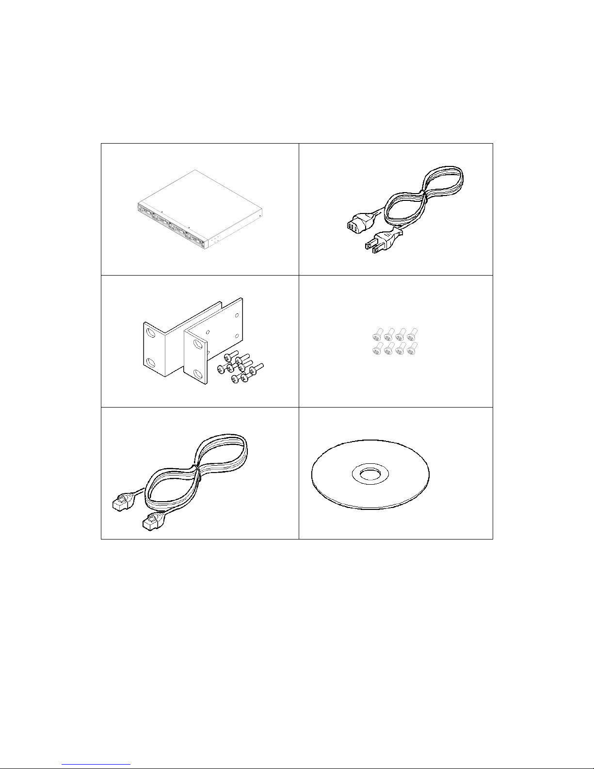
3. Supplied accessories
Unpack and check all the items as below;
1. NVS04S (1EA)
2. AC power code (1EA)
3. RACK fixing kit (1SET)
4. R-HDD fixing screw (16EA)
5. Gigabit Ethernet Cable (1EA)
6. CD-ROM (MANUAL)(1)
Page 10
10
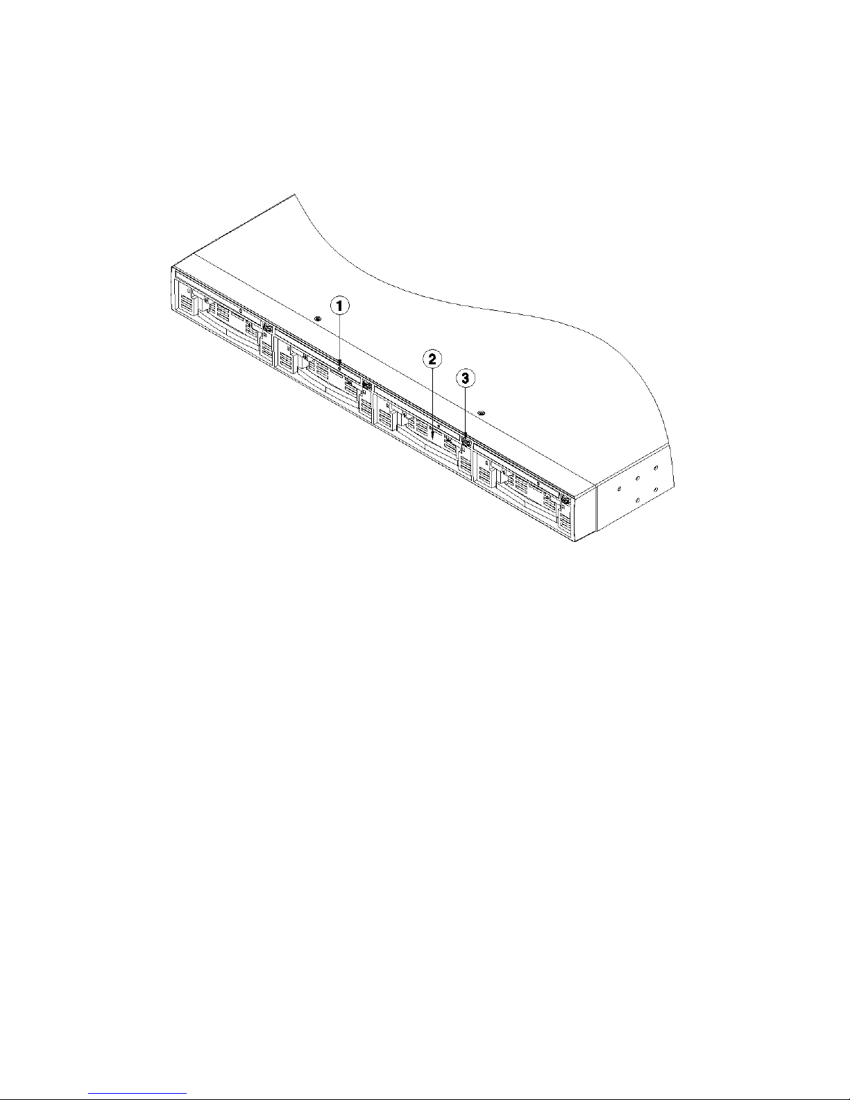
4. Description & Function
front
(1) LED
(2) Hard disk rack
(3) Rack separation button
Page 11
11
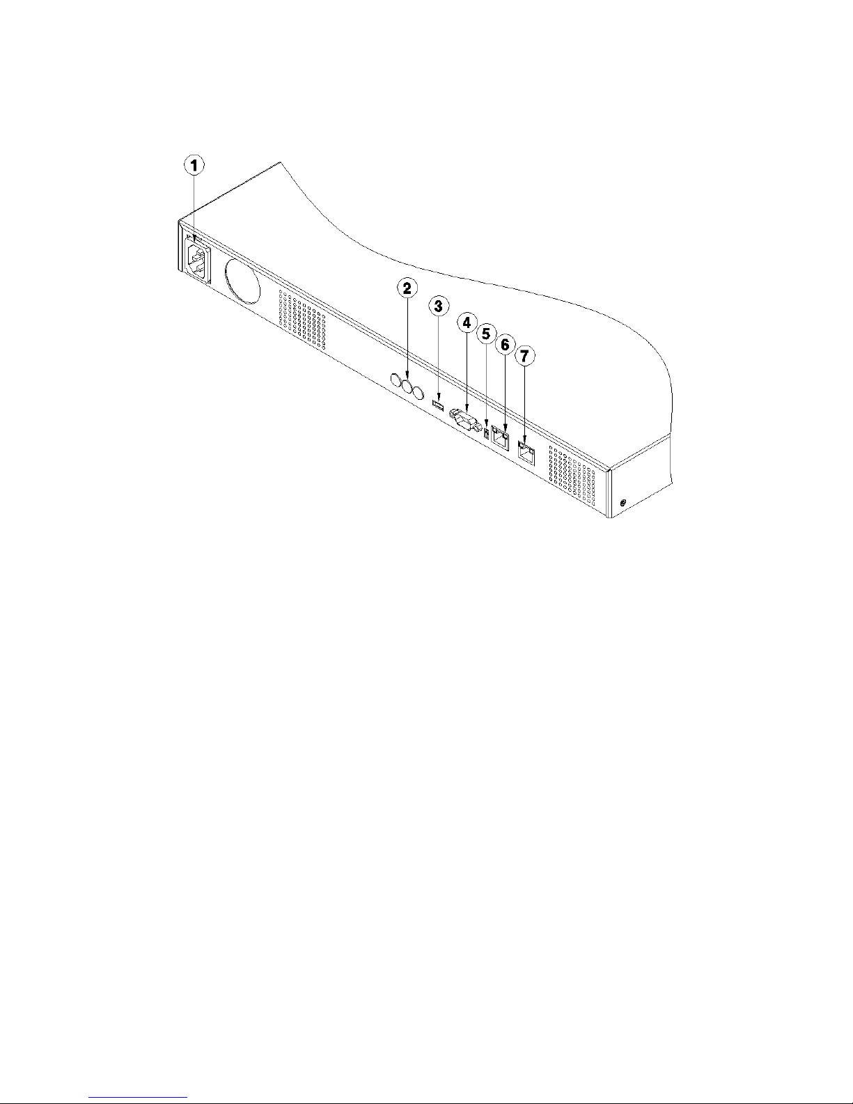
rear
(1) AC power connector
(2) Set ID rotary swith (Not Used)
(3) Mode switch (Not Used)
(4) RS232 connector (Text input)
(5) Alarm output connecting terminal (Not Used)
(6) Cascade or Private connector (RJ45)
(7) LAN connector (RJ45)
Page 12
12
Installation and Connection
5. Connecting & Running
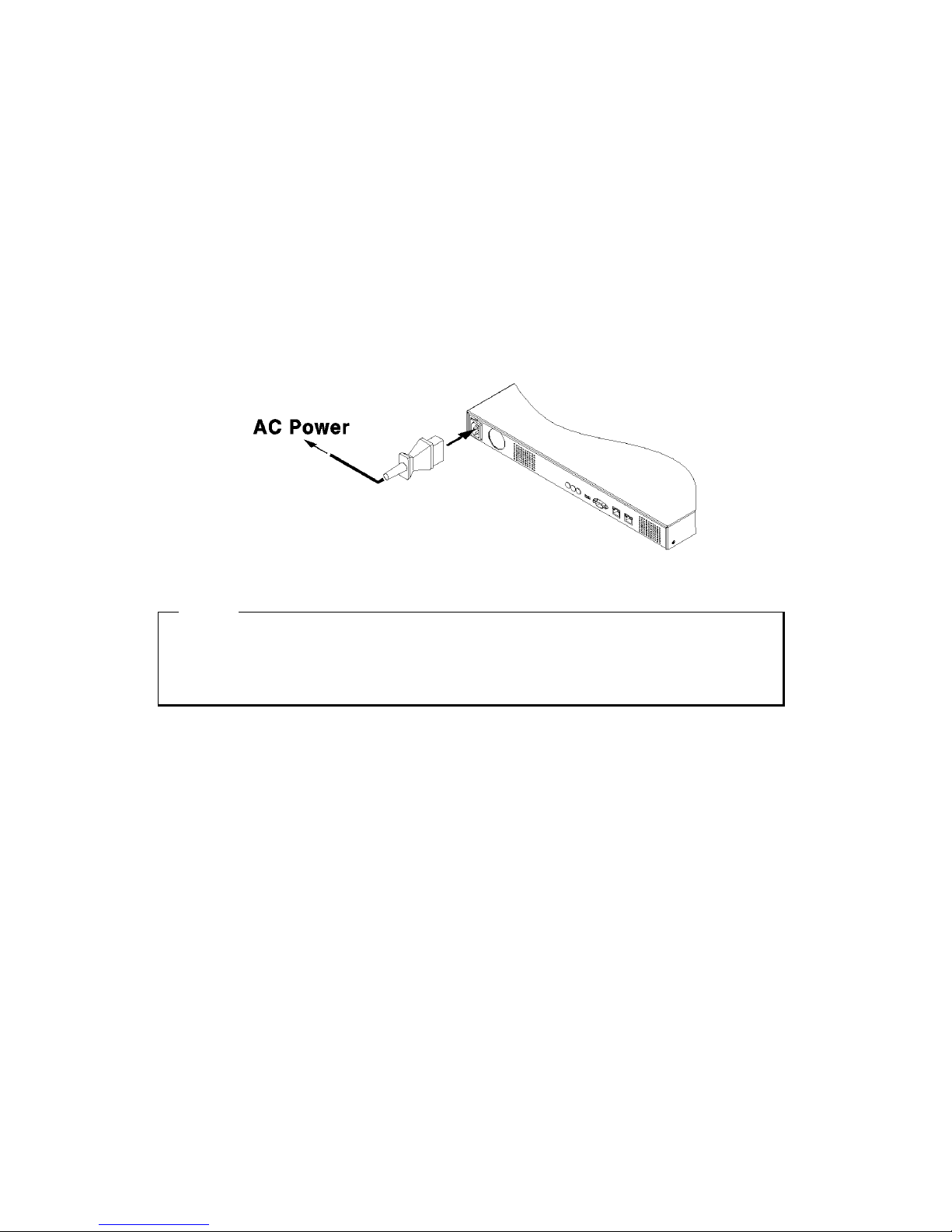
5.1. Power connection and operation
(1) Connect LAN port of NVS04S to the network connected IP Camera as below.
(2) It starts booting with power on.
<ote>
1. It takes around 1 minute to boot NVS04S.
2. While it sties connection, 4 LEDs on the front panel starts lighting and all of them starts
flickering and the user can check HDD list at Disk Manager.
5.2. Connect in Private mode
(1) Connect the Ethernet cable between the Lan port and PC.
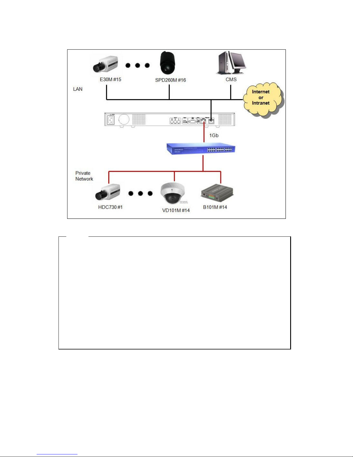
(2) Connect private port of NVS04 and hub connected to IP Camera
(3) Connect the power to IP camera after connecting AC power to NVS04S
(4) Execute Control Center Configuration Tool program at PC and configure the IP
camera connected to each channel.
(Refer the channel configuration with IP Camera at Configuration Tool at “8.1.3.2 IP Camera”)
Page 13
13
<ote>
1. The user can connect Private port and IP Camera directly.
2. IF the user configure the value of “1. Cam ID” at IP Camera’s OSD menu to the relevant channel
and it works.
3. When VS04S is connected to IP Camera v2.1.x.x, IP Camera changes its mode to recording
mode. Recording mode is limited to 2stream and the user can not change stream. When the user
wants to change stream at recording mode, the user needs to change saving configuration at the
recording channel of VS04S where the relevant IP camera is mapped.
4. Version below IP Camera v2.1.x.x do not support recording mode and VS04S is not able to be
connected to it.
5. To change the mode from recording mode to normal mode, separate VS04S from IP camera
and reboot.
Page 14
14
5.3. Connecting in Public mode
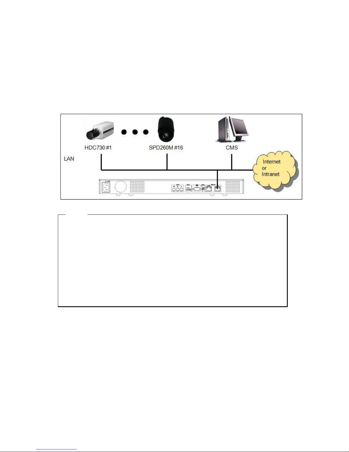
(1) Connect Lan port to local network using Ethernet cable.
(2) Execute Control Center Configuration Tool program at PC and type the IP Address of IP camera
connected and ID, Password to connect it with NVS04S. (Refer the manual at “8.1.3.2 IP Camera” to
select channel of IP camera)
<ote>
1. One single NVS04S is available to use Public and Private mode using each port.
2. IP camera changes its mode from normal to recording mode when VS04S is connected with IP
Camera v2.1.x.x Recording mode is limited to 2stream and the user can not change stream.
When the user wants to change stream at recording mode, the user needs to change saving
configuration at the recording channel of VS04S where the relevant IP camera is mapped.
3. Version below IP Camera v2.1.x.x do not support recording mode and VS04S is not able to be
connected to it.
4. To change the mode from recording mode to normal mode, separate VS04S from IP camera
and reboot.
Page 15

15
6. Using Control Center
Control Center List is a NVS04S Management Software and it makes NVS04S installtion & setting more
easier throguth a PC which is connected with NVS04S in Network. All configuration could be handled in
OSD menu of NVS04S without a PC, however, Control Center makes the complete setting more simply.
6.1. Starting
To do setting NVS04S through Control Center, PC and NVS04S should be connected via Network and installed
Contorl Center Lite on the PC.
6.1.1. PC system requirements for running Control Center
Mininum Requirements Recommended Requirements
CPU Intel Pentium 4 / 3.0GHz Core2duo E6750 or higher
Memory 1GB 2GB or higher
Video Card 128MB 512MB or higher
Resolution 1280 x 1024 (with 32bit color) or higher
HDD recording
space
80GB or higher
OS Windows XP Professional / Window Vista Business
Etc. DirectX 9.0 or higher
6.2. Installing Control Center
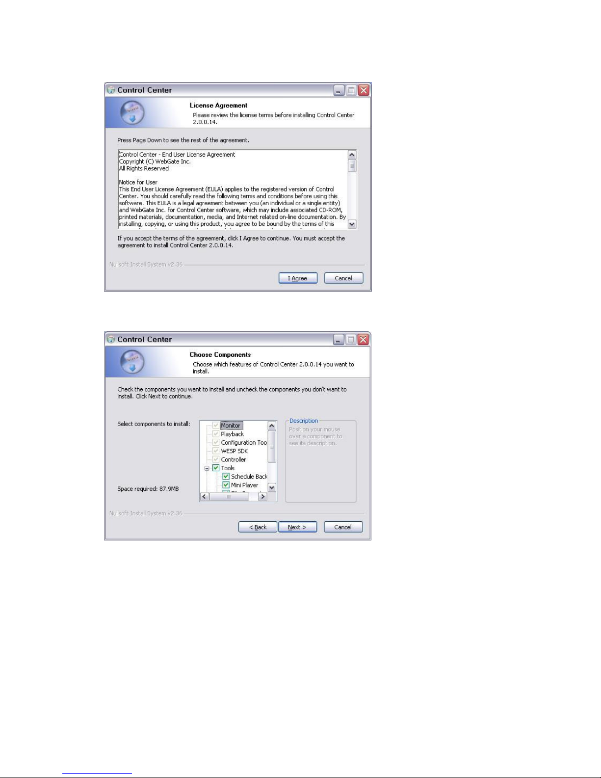
1) Execute “2.x.x.x Setup.exe” file in Control Center Set up CD.
To install Control Center, user level of the PC should be Administrator mode.
Page 16
16
2) Click “I Agree” button to accept the license agreement
3) Select components which wish to install and press “Next” button.
“WESP SDK” must be installed.
Control Center
Essential program should be installed to monitor via accessing Webeye.
Playback
Playback program should be installed to playback quick recording file.
Config
Webeye configuration program should be installed.
WESP SDK
Page 17
17
WESP libruary file to be used at Webeye should be installed.
Schedule Backup
Saving program to store NVS04S’s data to save by schedule at PC should be installed.
Tools
MiniPlayer, Fileconverter, Onetime Password should be installed.
DirectX Setup
DirectX should be installed.
Startup ShortCut
Registering at Windows start program to be executed.
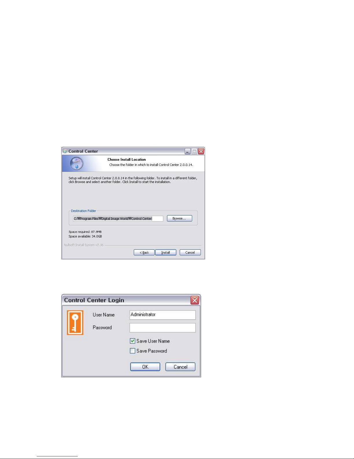
4) Click the “Install” button after selecting a directory to be insatalled.
6.3. Log-In
Enter User Name, Password and press “Ok” button.
The factory default value : User Name:Administrator, Password:admin
Page 18
18
6.4. Monitor
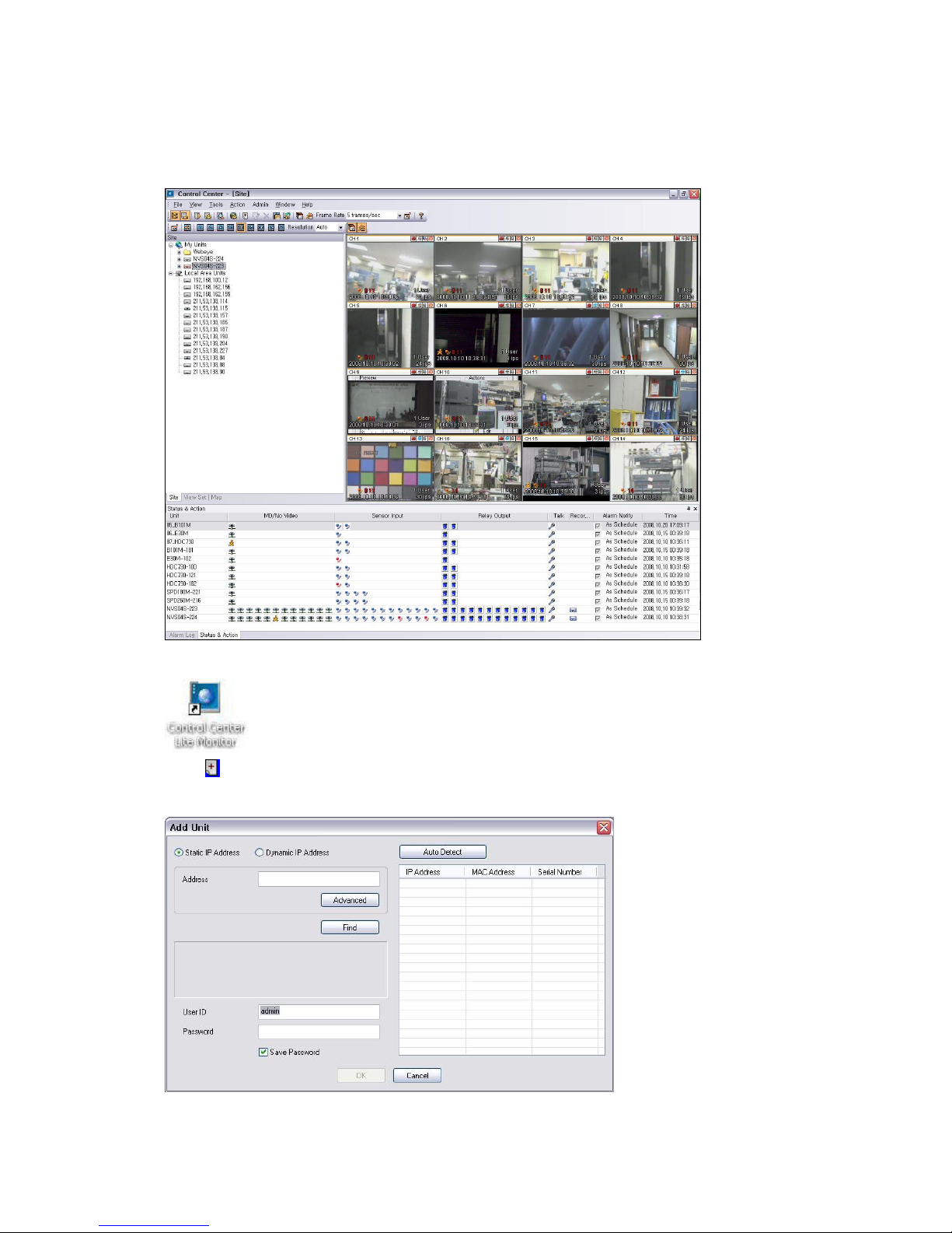
Click on the icone to execute “Control Center Monitor” program.
Drag and drop the unit located at Local Area Units to My Units or click on My Units and
select
“Add Unit” from pop up menu and registering box pops up. Or select add menu at Tool bar.
(Please check if the Add menu is diabled prior to change it.)
Page 19
19
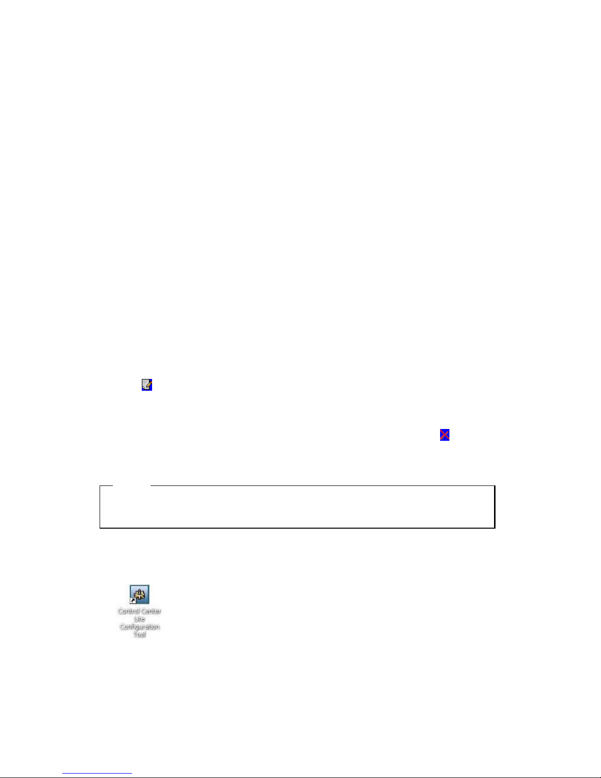
Static IP unit registeration
In case of registering unit by "Add Unit", input IP address on the message box and select "Find" button.
If its port number of unit is not 80, press "Advanced" and revise it. "OK" button will be active when
taking server information by server searching precess. Input user ID/PW and press "OK" button.
Basic information such as address is carried by drag and drop from Local Area Units. Input User
information and press "OK" button.
Dynamic IP Unit registration
In case of using Dynamic IP, register in Registration Server and manage it. Select "Dynamic IP Address"
radio button and input Registration Server and Serial Number and press "Find" button.
If search is ok, register user information.
Input WRS group ID and Registration Server and press "Find by group ID". If search is ok, units will be
listed up. Select Unit and input user information.
Unit information change
When changing registered unit information, select unit and "Edit Unit" and Dialog box will be displayed.
Or select
"Edit" menu. user can change port no. and user information.
Delete Unit
To delete the registered Unit, select Unit and “Delete Unit” in pop-up menu. Or select “Delete” in
Toobar.
<ote>
1. For more detailed function and user manual of Control Center, please, refer to the Contro Center Lite
User guide.
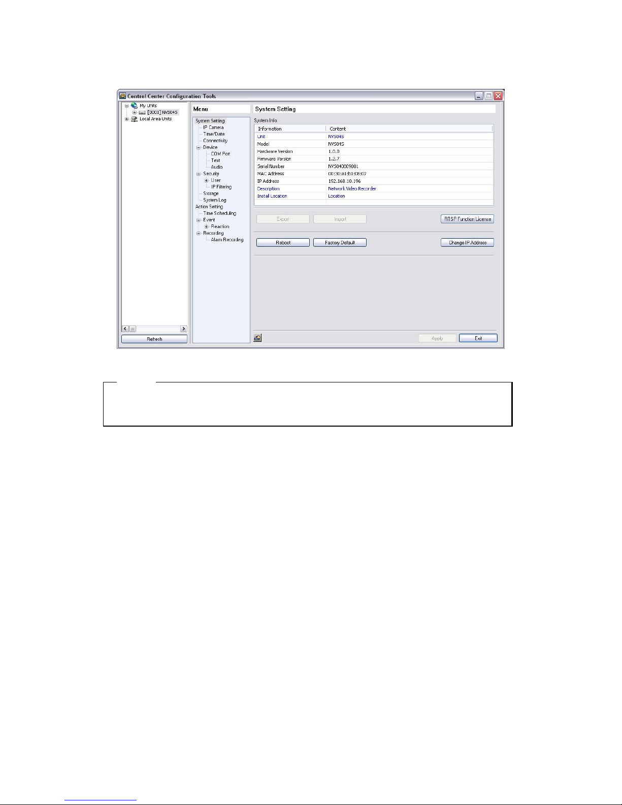
6.5. Configuration Tool
Click the icon on the desk top to run “Control Center Configuration Tool”.
Page 20
20
<ote>
1. Configuration of NVS04S by Configuration Tool, please, refer to the chapter 7 user guide.
Page 21
21
6.6. Playback
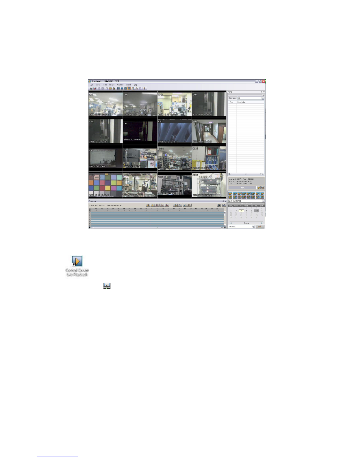
NVS04S plays back the recorded video by up to 2 users a unit using Control Center Playback program.
6.6.1. Open Back-up file and Unit
Click icon on desktop and execute “Control Center playback”.
Select File>Open
menu. Unit tree registered as My Unit appears via Contro Center Lite. Only
searchable Unit with HDD appears. If wanting to search Unit, select unit and press “OK”.
If wanting to search recorded back-up file, press “Open Backup File” and select the file.
If opening unit at first, it will be searched by date of last recording. Search block will be adjusted by
recorded time data in last day. (If recorded for 4 hours in last day, search block is 6 hours)
Page 22
22
User’s Guide
7. Description
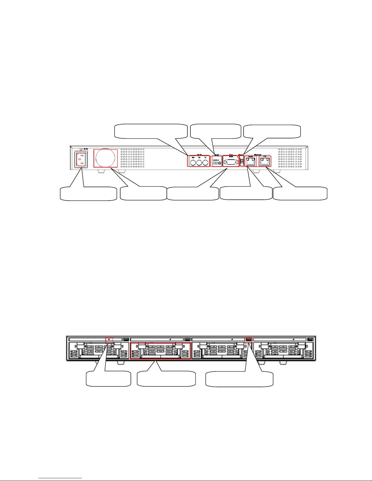
7.1. Rear Part
(1) Power connection
(2) Cooling Fan
(3) Rotatory Switch(not use)
(4) Mode switch(not use)
(5) RS232 Connector(Text input)
(6) Alram output (not use)
(7) Cascade or Private connector
100/1000 Ethernet(RJ45)
(8) Lan connector
100/1000 Ehternet(RJ45)
7.2. Front Part
(1) Rack LED
- Green : Recording and Playback
- Red : Recording and Playback standby
(1) Power connection
(2) FAN
(3)Set ID Rotator Switch (4) Mode Swtich
(5)RS232 Connector
(6) Alram output
(7)Private Connector
(7) LAN Connector
(1) Rack LED (2) HDD disk rack
(3) Rack removal button
Page 23

23
- Off : Not working
(2) HDD disk Rack
(3) Rack removal button
7.3. Installation summary
- Camera connection
- Ethernet connection
- Power connection and operation
Page 24
24
8. VS04S Configuration
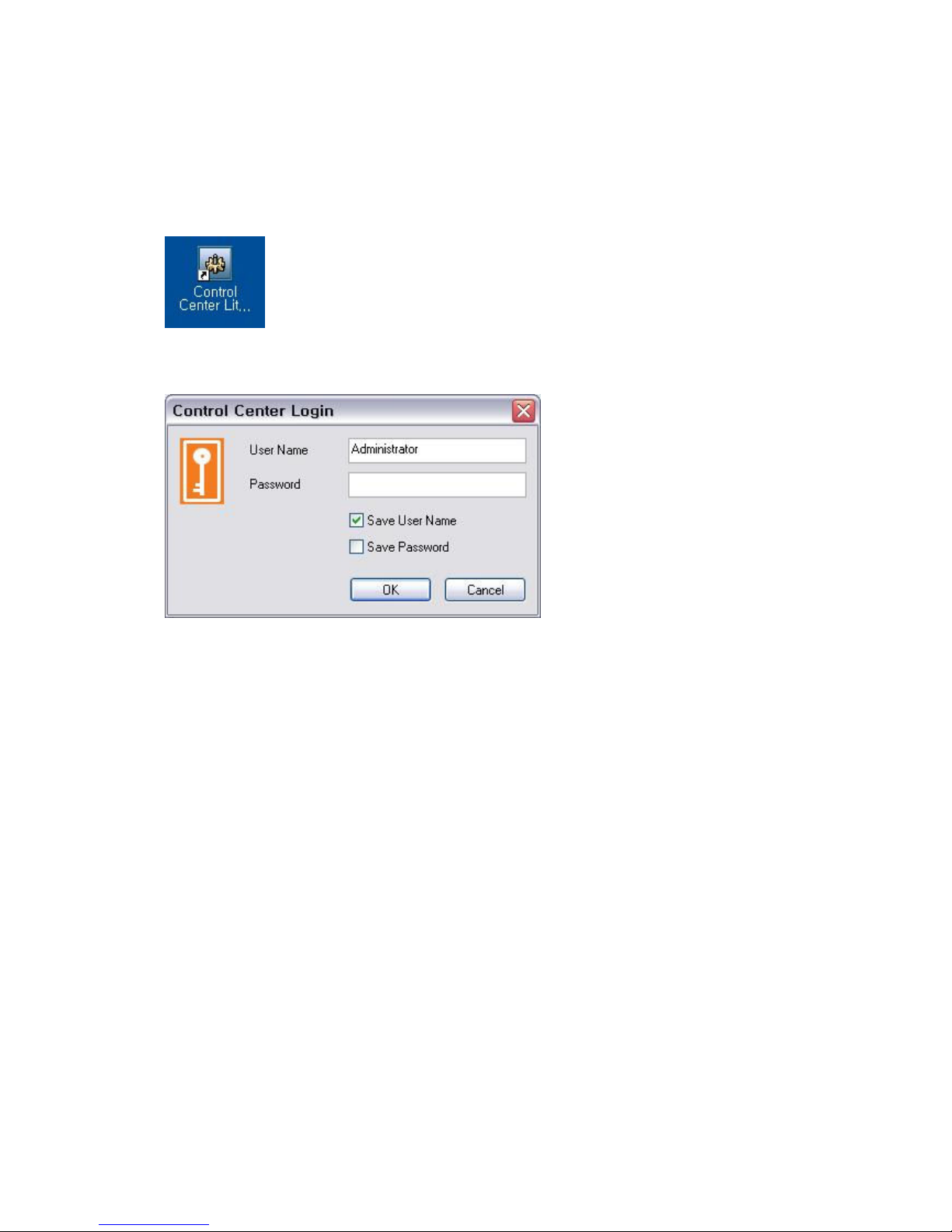
8.1. Log in Configuration Tool
(1) Click icon to run “Control Center Configuration Tool”.
(2) Program Log in..
Click on “OK” button after inputting ID and Password. When login becomes accomplished normal way,
Control Center program will be running. The user who is registered as Default is “Administrator” and
password is “admin”
Page 25
25
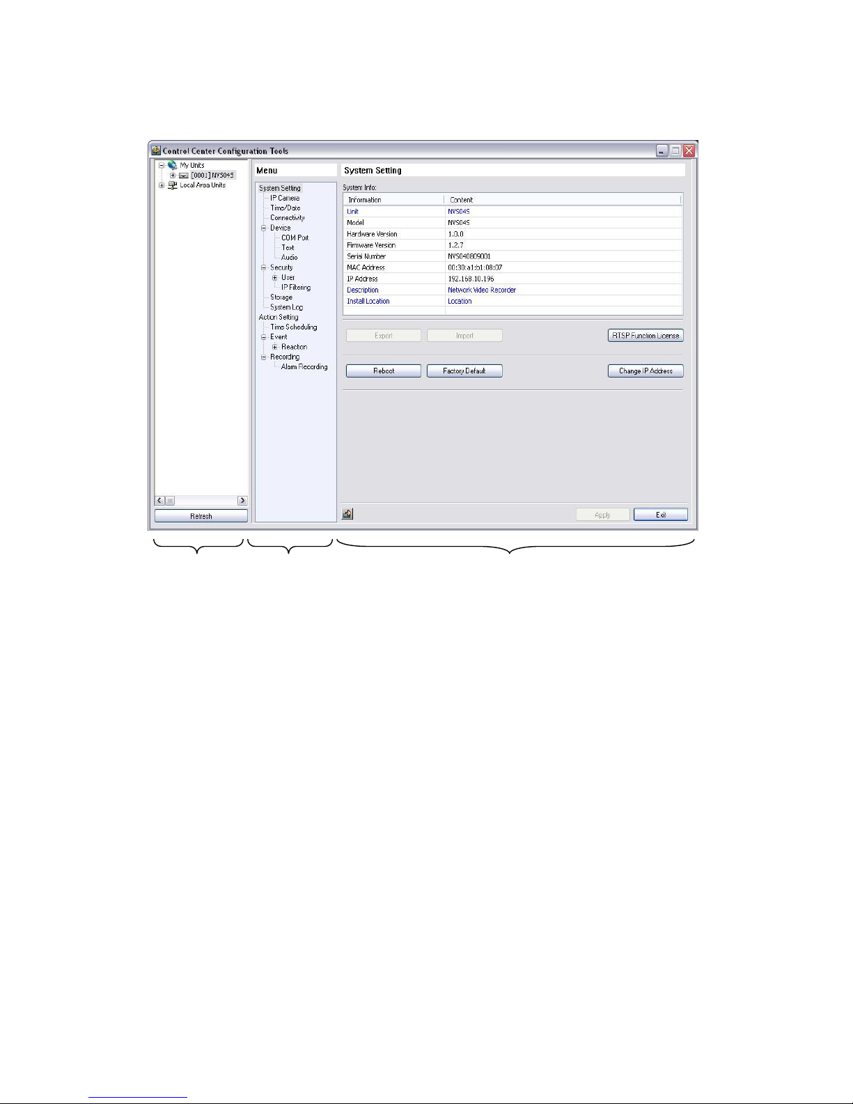
8.2. Interface
The full screen of Configuration Tool is as above and its contents are such as site tree, menu and
configuration page.
8.2.1. Site Tree
The units which is listed in unit tree are registered in main view of Control Center and it is not possible
for user to register/delete/revise them using Configuration Tool.
The list is periodically synchronized with “My Units” of Control Center. And when user press the
“Refresh” button in lower part, all the information will be renewed rightly.
The details which user can configure will appear in menu if user clicks specific unit. System setting page
will also appear default value in configuration page.
8.2.2. Menu
The details of menu are different according to model type of unit. Setting page relating to details will
appear in configuration page if user click menu.
Site Tree
Menu
Configuration Page
Page 26
26
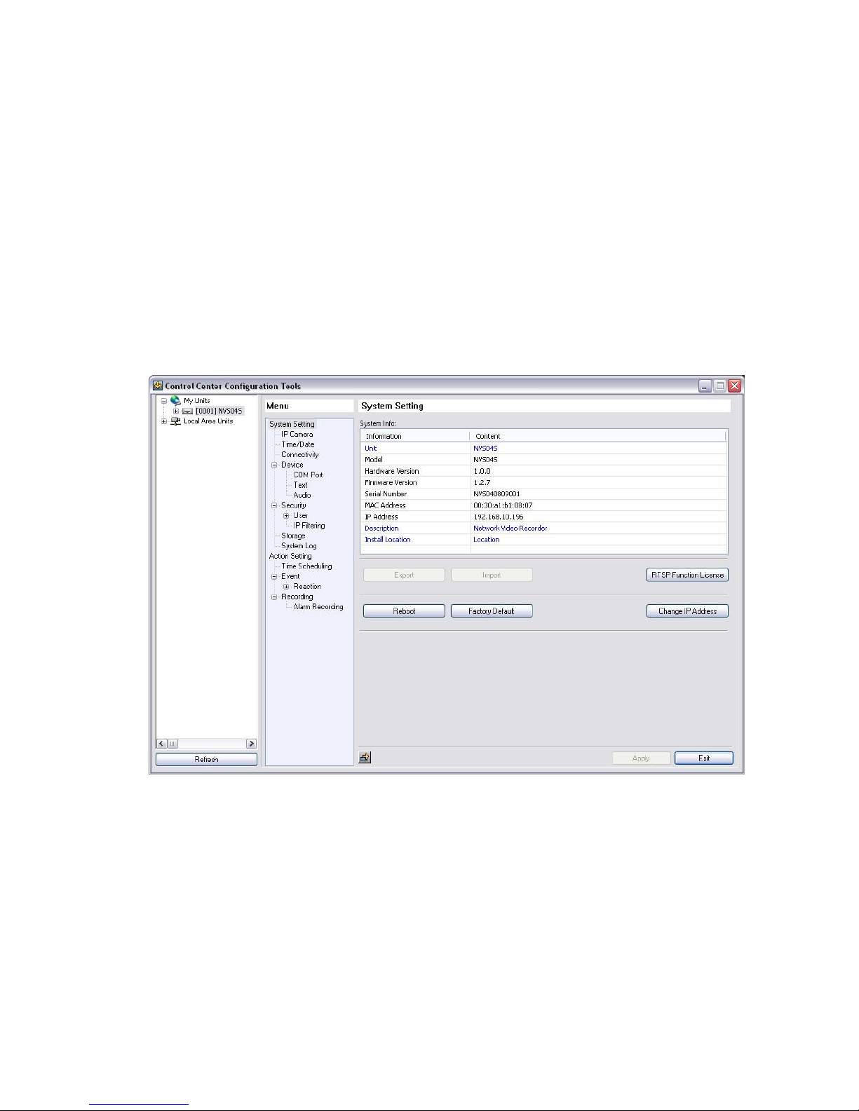
8.2.3. Configuration page
As “Apply” button will be activated when user changes configuration of the page, user will just press this
button to apply new configuration.
User should press “Apply” button after changing setting of each configuration page.
If user moves to another configuration page without pressing “Apply” button, dialogue box will appear to
ask user whether new configuration will be applied.
8.2.3.1. System Setting
System Info
It displays basic information of i-Rec. Things like blue-lettered Unit, Description, Installed Location can
be edited with double click.
Press “Apply” button after editing.
Reboot
It is for rebooting NVS04S.
Page 27
27
Factory Default
It is for changing configuration into factory default value.
<ote>
Z
The information such as date, time, network setting and image type (NTSC/PAL) will not be change
even if configuration is changed to Factory Default.
8.2.3.2. IP Camera
8.2.3.2.1. IP Camera Configuration
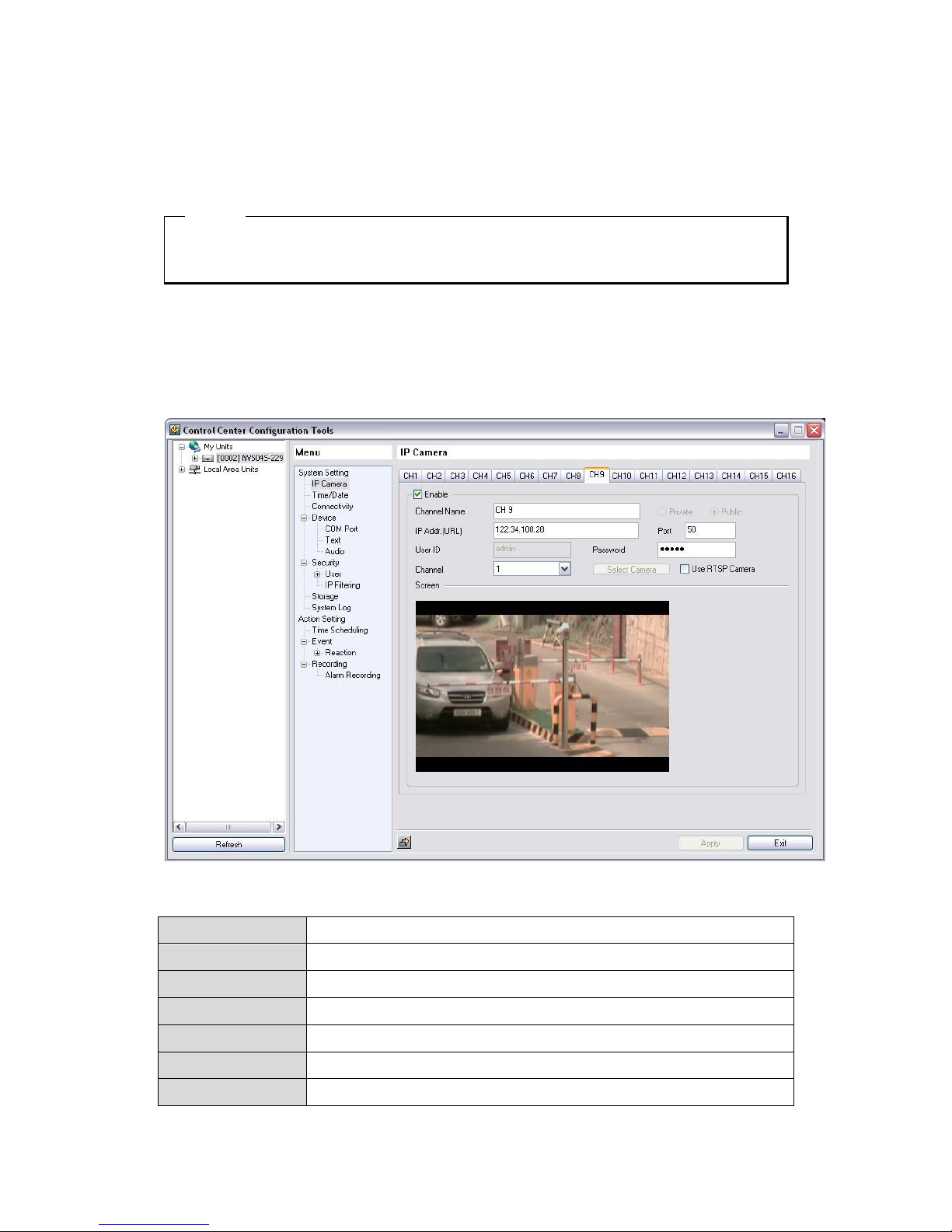
NVS04S can configure IP camera by Public mode or Private mode per channel.
Channel information
- Enable Input yes or no of channel usage.
- Channel Name Input channel name.
- Private Connecting IP Camera connected to Private Port.
- Public Configure when connecting IP camera to remote or local network.
- IP Addr.(URL) Input URL or IP address of IP camera connecting by Publich mode.
- Port Input Port of IP camera connecting by Publich mode..
- User ID Input user ID of IP camera connecting by Publich mode.
Page 28
28
- Password Input user password of IP camera connecting by Publich mode.
- Channel Input Channel of IP camera connecting by Publich mode.
- Select Camera Configure IP camera connected to NVS04S Private.
- Use RTSP Camera Click to use RTSP camera
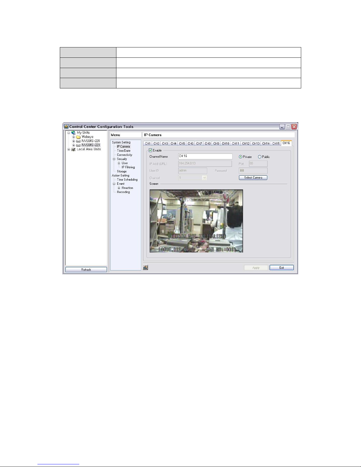
Channel configuration using Private Mode
NVS04S can configure IP camera connected to Private Port.
1) Connect IP camera to NVS04S Private port directly using Ethernet cable or Hub.
2) Access to NVS04S executing Configuration Tool.
3) After select Private in IP Camera Menus and click “Select camera”.
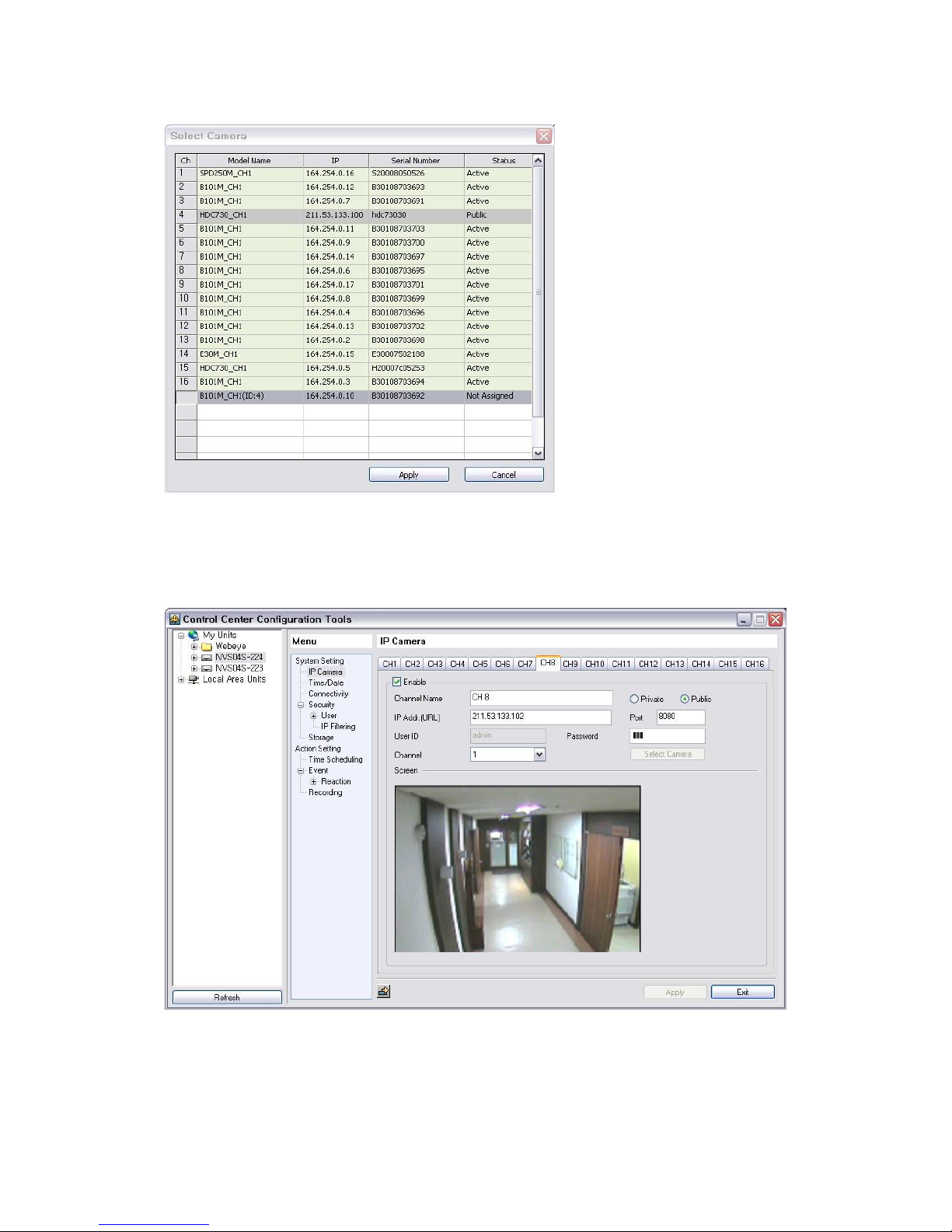
4) After selecting IP Camera not configured channel in Select Camera and do “Apply”
Page 29
29
5) If configuration is normally finished, video of IP camera configured will be on the screen.
Channel configuration using Public Mode
NVS04S can configure IP camera connected to remote or local network like below.
1) Connect local network connecting IP Camera to Lan port of NVS04S using Ethernet cable.
2) Access to NVS04S executing Configuration Tool
3) After input IP Address, Port, User ID, Passwrod, Channel of IP camera and do “Apply”
Page 30
30
4) If configuration is normally finished, video of IP camera will be on screen.
<ote>
1. One NVS04S can use Private per each channel and Public mode concurrently.
2. If IP camera connect to vS04S, IP camera is transfered from normal mode to recording mode.
In recording mode, stream is restricted up to 2 and can not change it. In case that changing
stream in recording mode, user should change recording setup in recording channel of VS04S
which mapping IP camear.
3. To transfer from recording mode to normal mode, remove IP camera in VS04S and reboot.
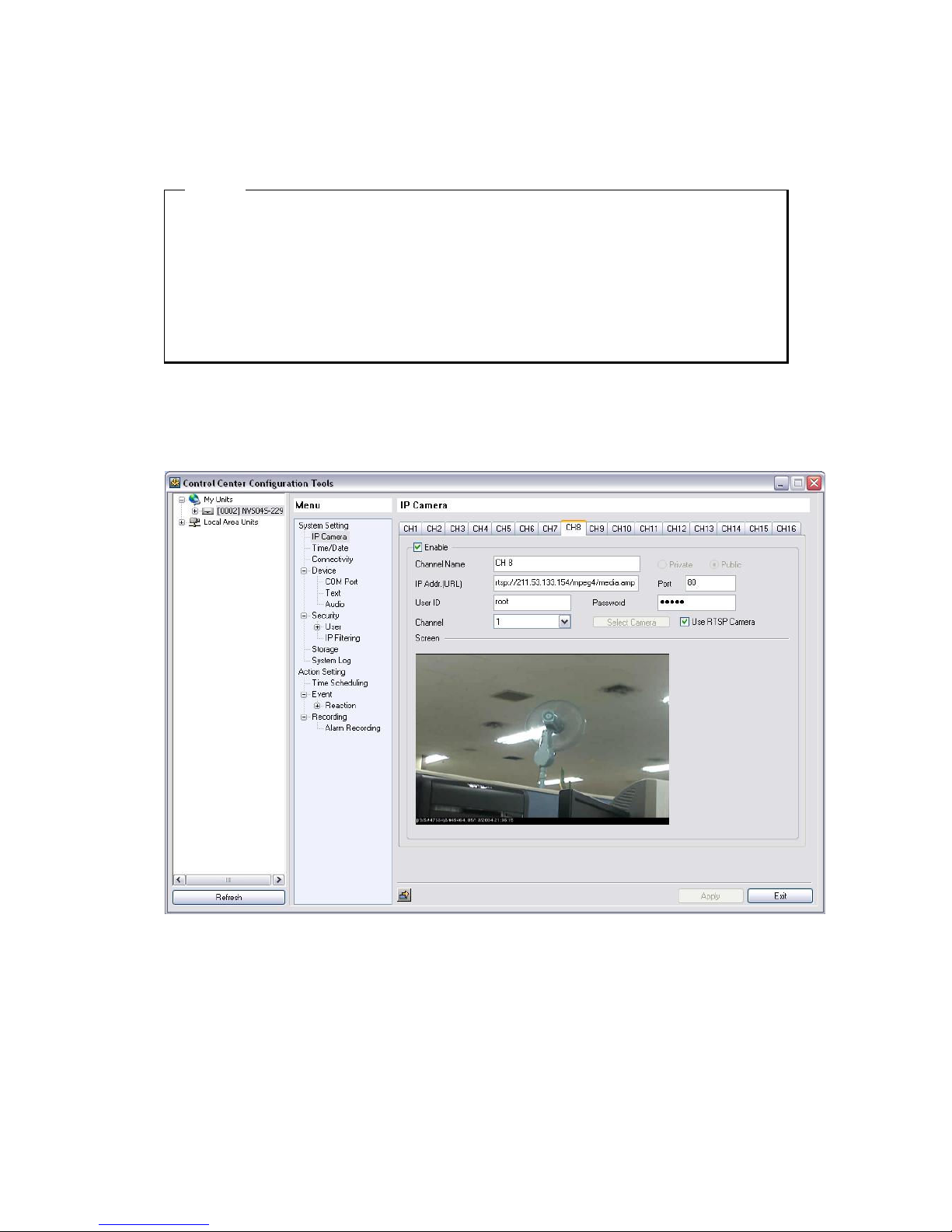
Configure RTSP(Real Time Streaming Protocol) camera
Set the IP Camera of RTSP function as follows.
1) Input RTSP Function License in System Setting page.
2) ‘Use RTSP Camera’ menu is activated in each channel tap after entering ‘RTSP Function License’.
3) Click ‘Use RTSP Camera’ in related channel then ‘rtsp://’ is appeared in ‘IP Address’ and ‘User ID’
is activated.
4) Input the related ‘RTSP address’ in IP Address,‘User ID’, ‘Password’ and click ‘Apply’ at bottom,
Then RTSP Camera is connected.
Page 31
31
<ote>
1. Small fee is required for ‘RTSP camera connection’. Please get ‘RTSP licensed’ to use this function.
2. Please contact where you purchasing to get information about RTSP camera.
3. It can be take a few seconds to Video output in live monitoring or playback
and it also can be playback one frame per several seconds, depends on a connected RTSP Camera,
installation condition
Please note that it is not caused by NVS04S, but a connected RTSP Camera or network
condition
8.2.4. Time/Date
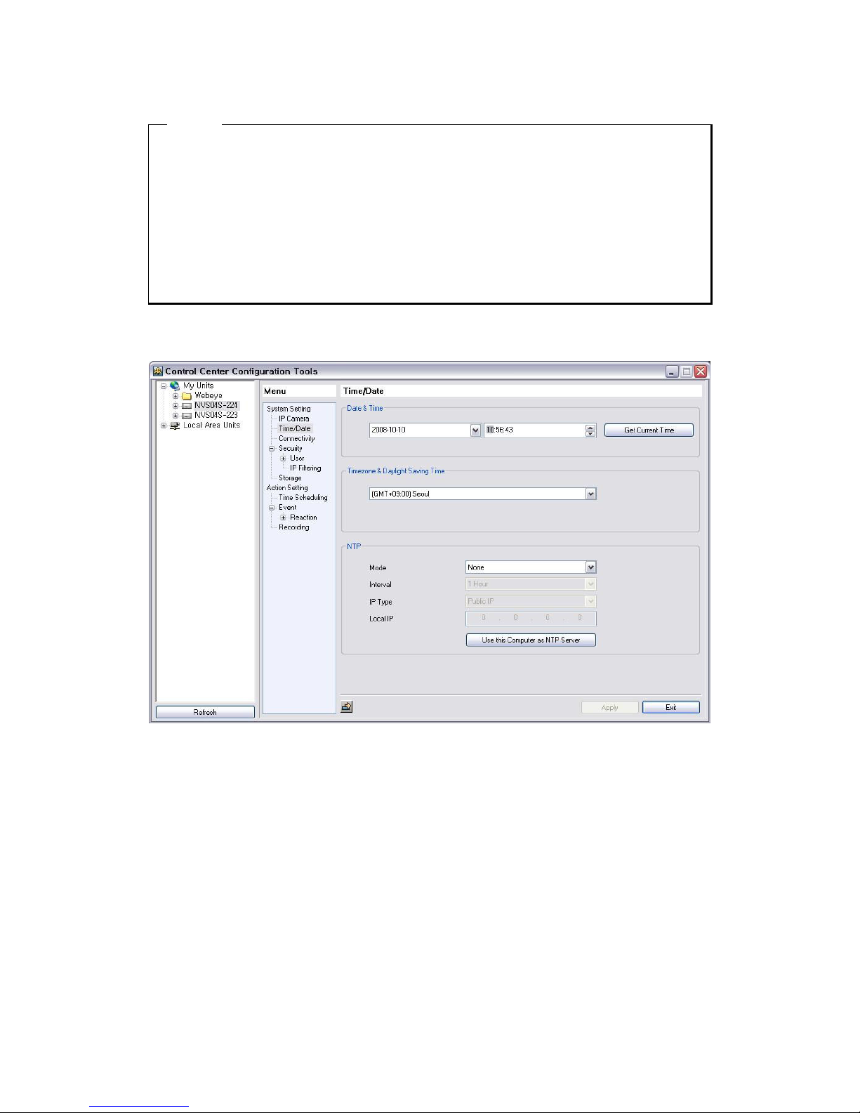
8.2.4.1. Setting Date & Time
Date & Time
It shows Date & Time of NVS04S. Setup can set in menu of local unit.
Timezone & Daylight Saving Time
It shows the time zone that NVS04S is installed. If it set to Summer time zone, the Control displays to
select applying Daylight Saving Time(DST) or not. When DST set to On, DST operates as same type one
of MS Window.
Page 32
32
<ote>
Z
If Time zone is changed, add time as much as the Time zone to current time.
Ex) If current time is +01:00(Amsterdam) 01:25 and if change this time to +09:00(Seoul) , it will be
+09:00(Seoul) 10:25.
8.2.4.2. TP Setup
NTP (Network Time Protocol) is the function to sync the time with device which can be standard on the
network.
- Mode : Select Server/Client/Both. At Server mode, NVS04S supply the time by itself and gets
the time from Time Server at Client mode. It works as Server & Client in both modes
at the same time.
- Interval : When NTP mode is Client, select a period of time to get. (1/3/6/12/24Hour.)
- IP Type : When it gets Time data from NTP server opened in Internet, select Public IP. When it
gets the time from NTP server indicated by user, select Local IP. (Public IP/Local IP)
- Local IP : When IP Type is Local IP, input NTP Server IP.
8.2.5. Connectivity
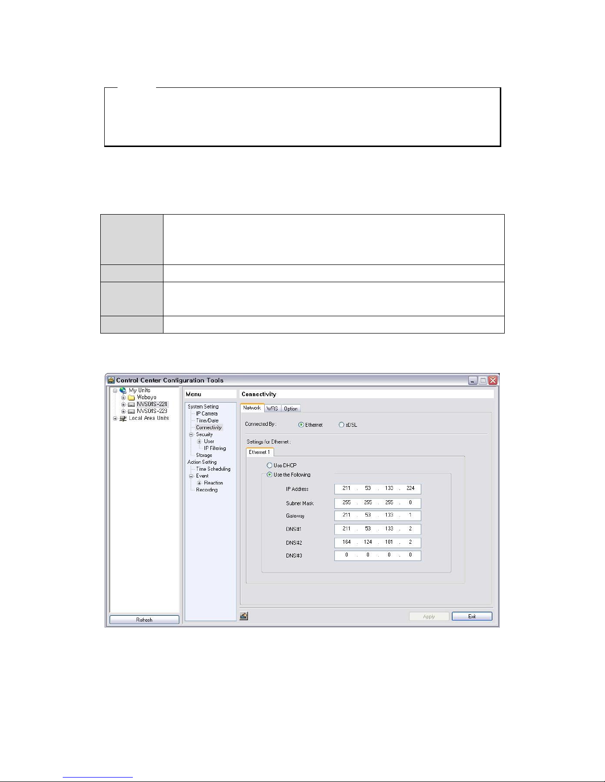
8.2.5.1. When using Ethernet
Select “Use DHCP” If user uses dynamic IP address. Input IP address, subnet mask, gateway and DNS
server if user uses static IP address.
Page 33
33
<ote>
Please ask network administrator or IPS about things such as static IP address.
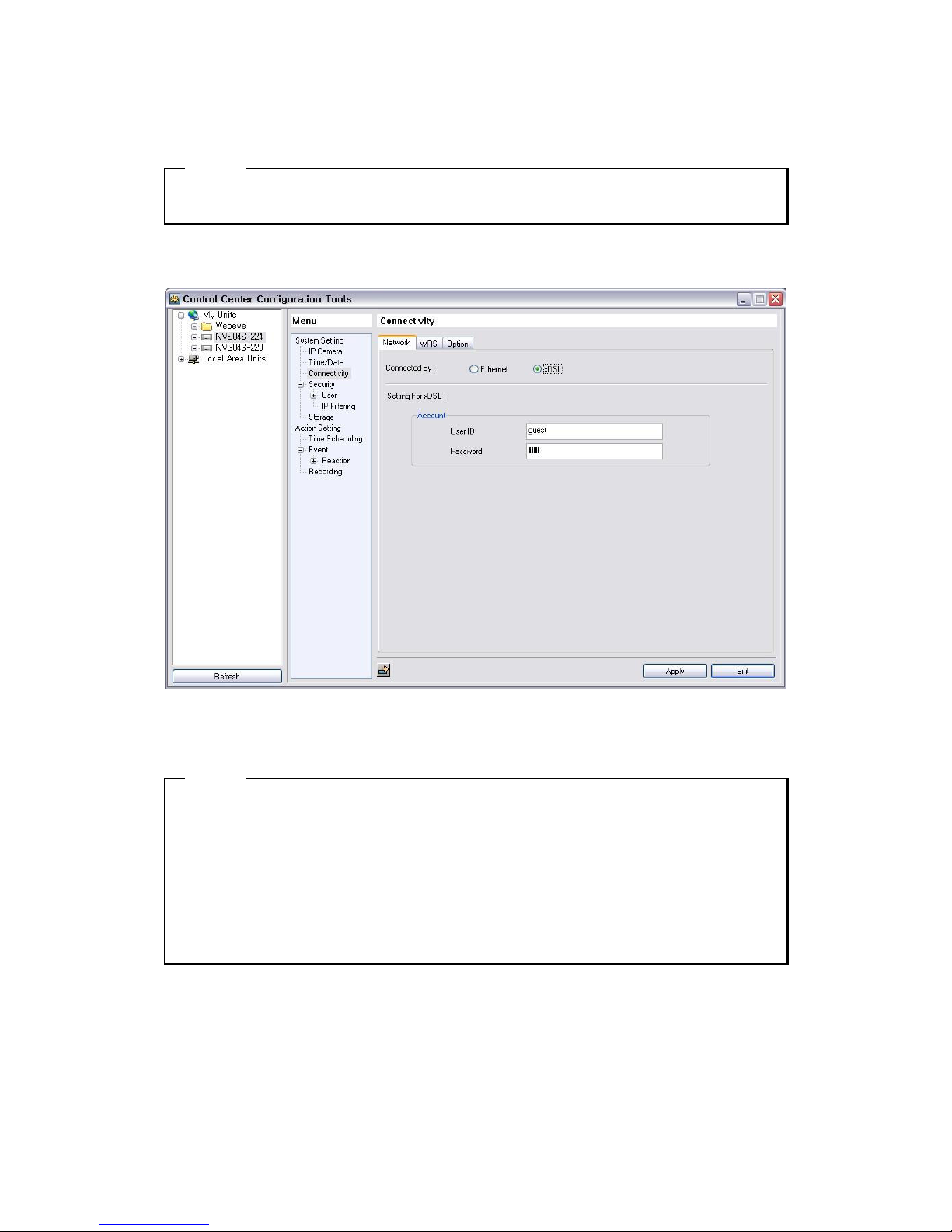
8.2.5.2. When using xDSL
Select xDSL if network is xDSL (ADSL, HDSL, VDSL) and set user ID, password.
<ote>
1. xDSL has various types such as ADSL, HDSL, VDSL, it can be used by PPPoE protocol.
2. Set WRS when using xDSL type. (except using static IP address)
3. Can not connect network by using ethernet xDSL.
4. User ID and password will be provided by xDSL ISP.
5. Network setting must be ethernet though network is xDSL type if user uses automatic connection
modem.
Page 34
34
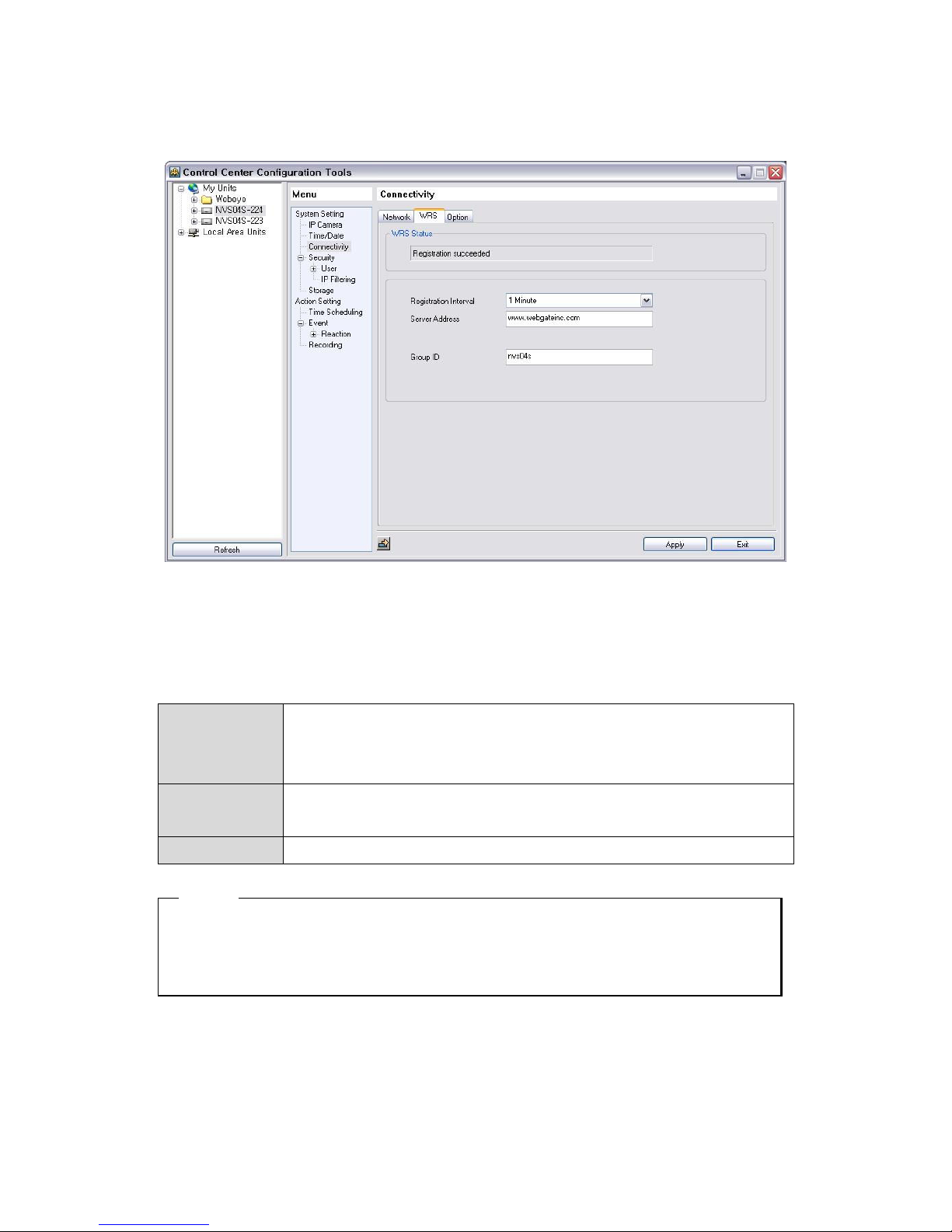
8.2.5.3. WRS (Dynamic IP Registration Sever)
If user registers i-Rec in WRS (Dynamic IP address registration server) managed by WEBGATE, user
will be free from inconvenience. Since user can not know exact dynamic IP address at every moment,
user needs something such as WRS that can give IP address of NVS04S.
- Registration
Interval
: Sets time interval when dynamic IP address is registered in WRS. If IP address is
changed frequently, user had better set interval 1minute.
(1minute /1hour /3hour /6hour /12hour /24hour)
- Server Address : IP address of WRS that is managed by WebGate is “www.webgateinc.com”. User
should input its IP address if user designates other server.
- Group ID : Selects group where NVS04S will be registered.
<ote>
Dynamic IP registration is necessary in case of as follows.
- In case of using DHCP in ethernet
- In case of using xDSL (except static IP address)
Page 35
35
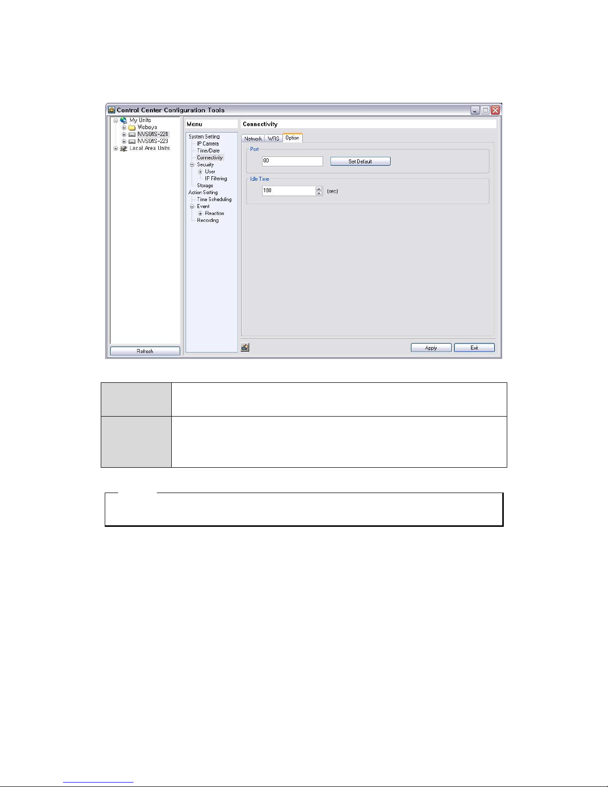
8.2.5.4. Setting Port
- Port : User should change port number if user can not connect NVS04S because of
network problem such as firewall.
- Idle Time : User can set idle time. User can wait for reconnection during idle time if connection
is closed because of network problem. If waiting time exceeds idle time connection,it
will be fully closed. Default value is 3 minuntes (0~3600 second)
<ote>
User should reboot NVS04S if user changes connectivity setting.
Page 36
36
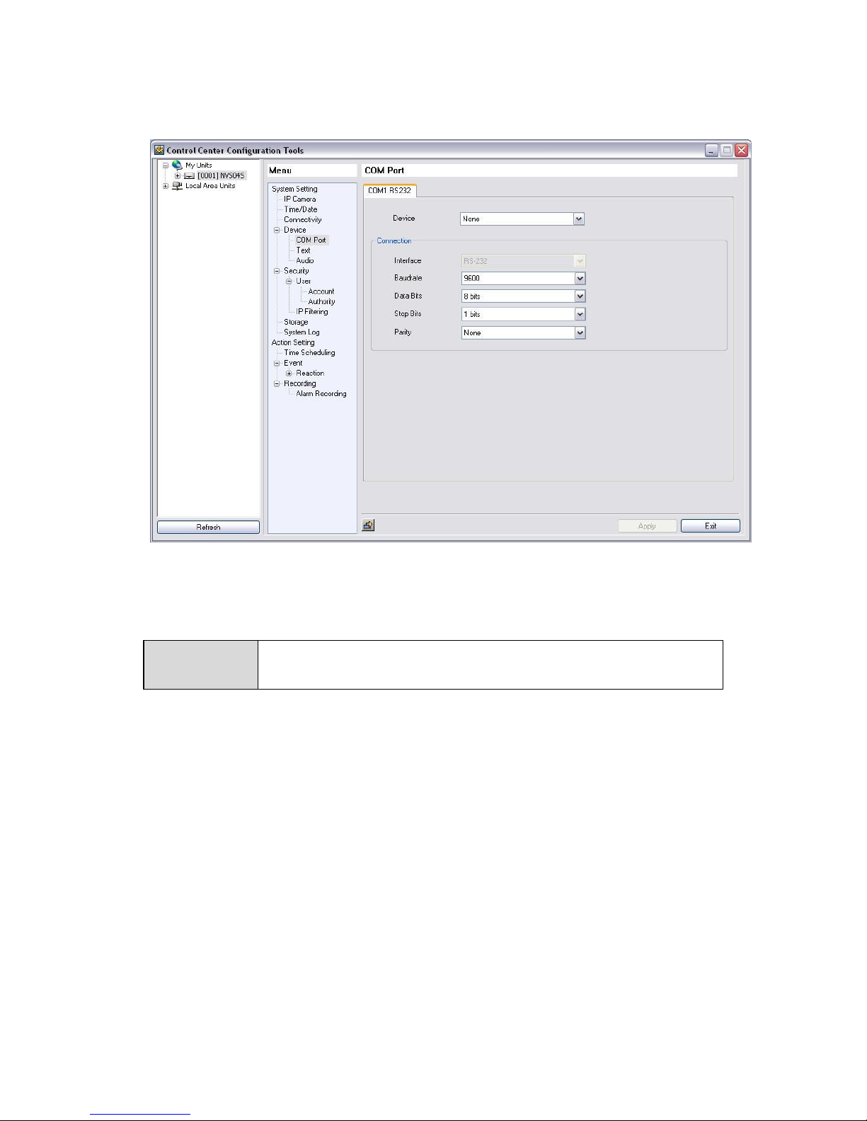
8.2.5.5. Com Port
User can set com port and devices in com port page. Tab number indicates each port number.
8.2.5.5.1. Selecting device linking port
User can connect devices such as Text to serial port.
- Text : Select when connects text device. Then if it likes to go Text setup page, click “Go”
button.
Page 37
37
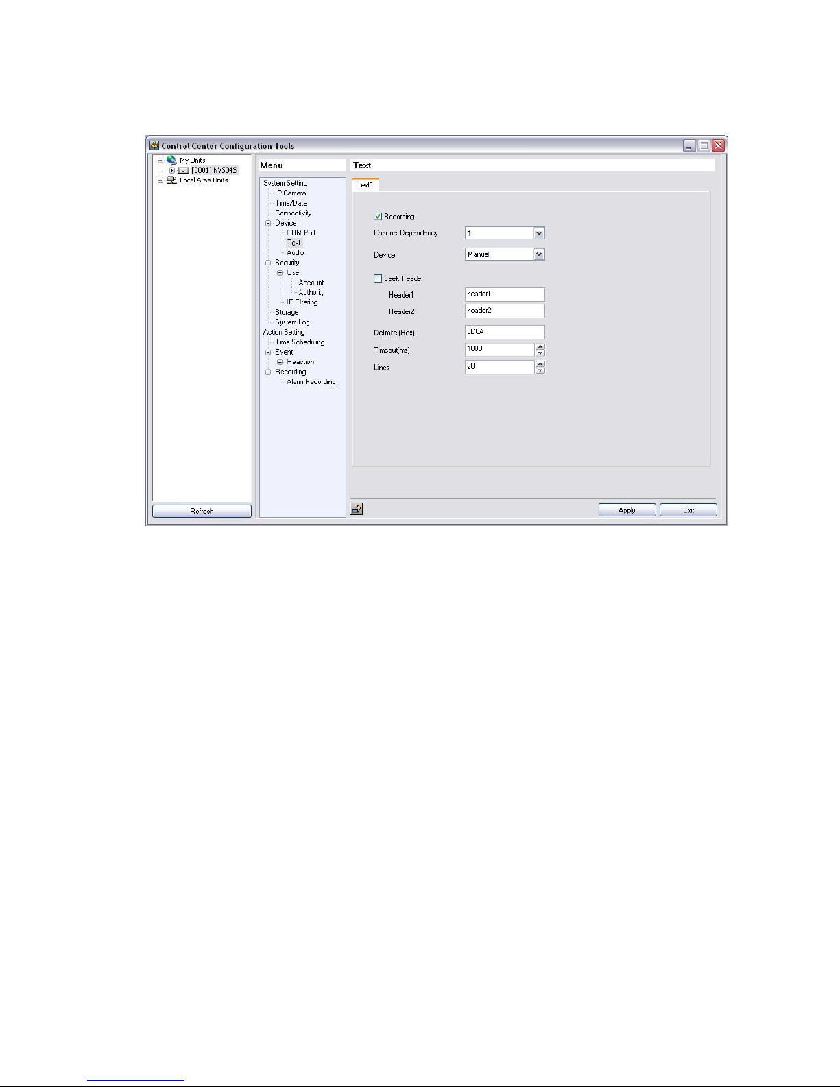
8.2.5.6. Text
Set Recording menu to ‘On’ and set Sync channel to the wanted value. If connectable devuce is Star
Finger 007,VSI Pro, set the relevant device only. And et other products to Manual and set all inferior
menus.
.
Page 38
38
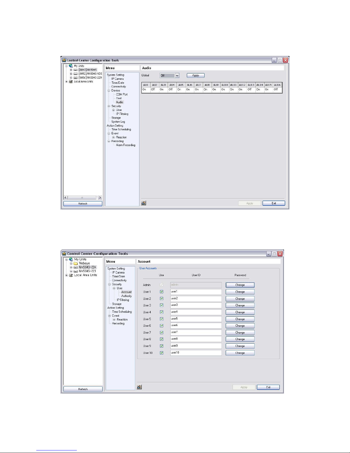
8.2.5.7. Audio
NVS is mapping 1:1 with Audio of IP Camera in each channel.
Save Audio data input to mapping channel with checking Recording.
8.2.5.8. User Accounts
Page 39
39
There are two kinds of user, one is administrator, the other is common user. The administrator has
especially authority relating to changing setting of i-Rec including all authority. Common user can have
all authority except setting.
The administrator ID is fixed as “admin” and user can change only password.
User can add maximum four of user ID. Initially ID is “user1, user2…user10”.
ID and Password can be configured up to 15 characters in English and 7 character in Krean.
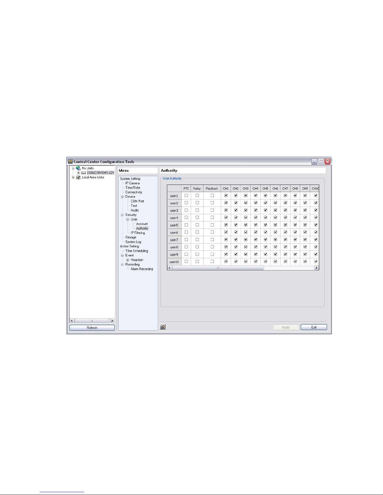
8.2.5.9. User Authority
User can set user’s authority according to Microphone, PTZ, relay out, HDD, channel viewing.
Registered “user1. user2…user10” has only authority of all channel viewing.
Page 40
40
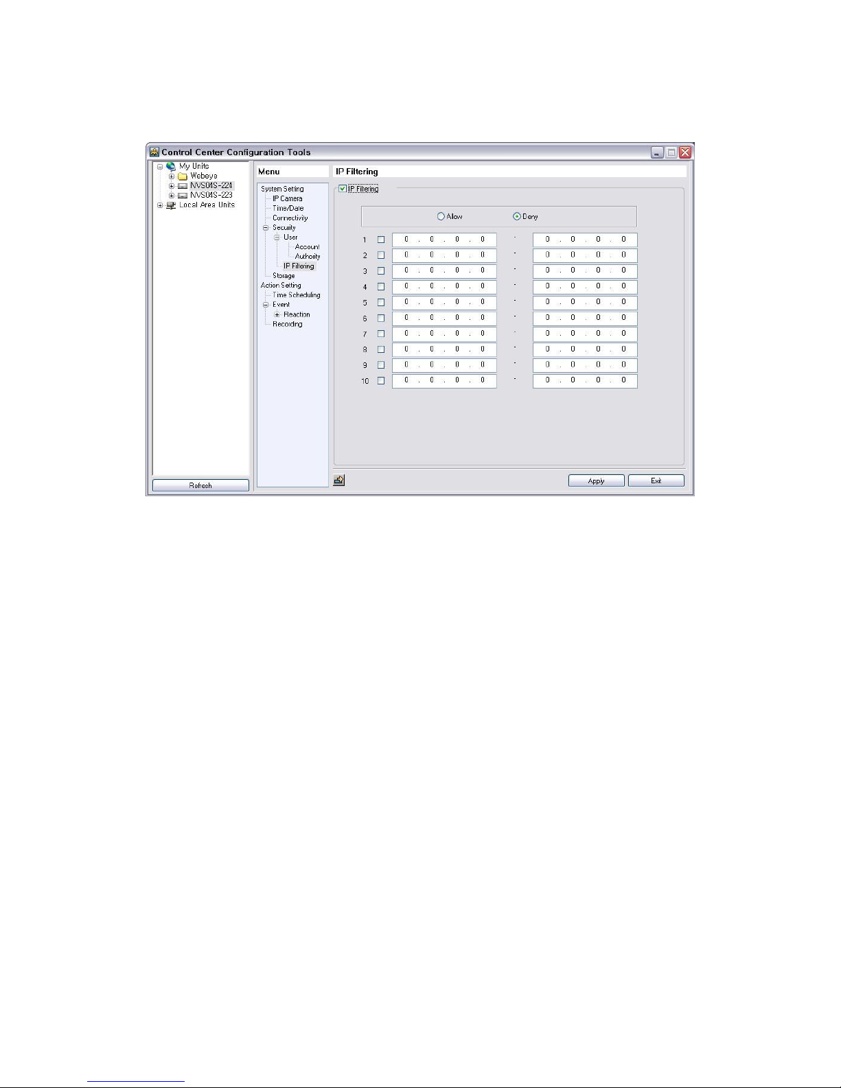
8.2.5.10. IP Filtering
User can give access authority of i-Rec by using IP filtering. It is allowed to access If IP address is
registered “Allow”, and it is not allowed to access if IP address is registered “Deny”. Total ten IP can be
registered in each category.
Page 41
41
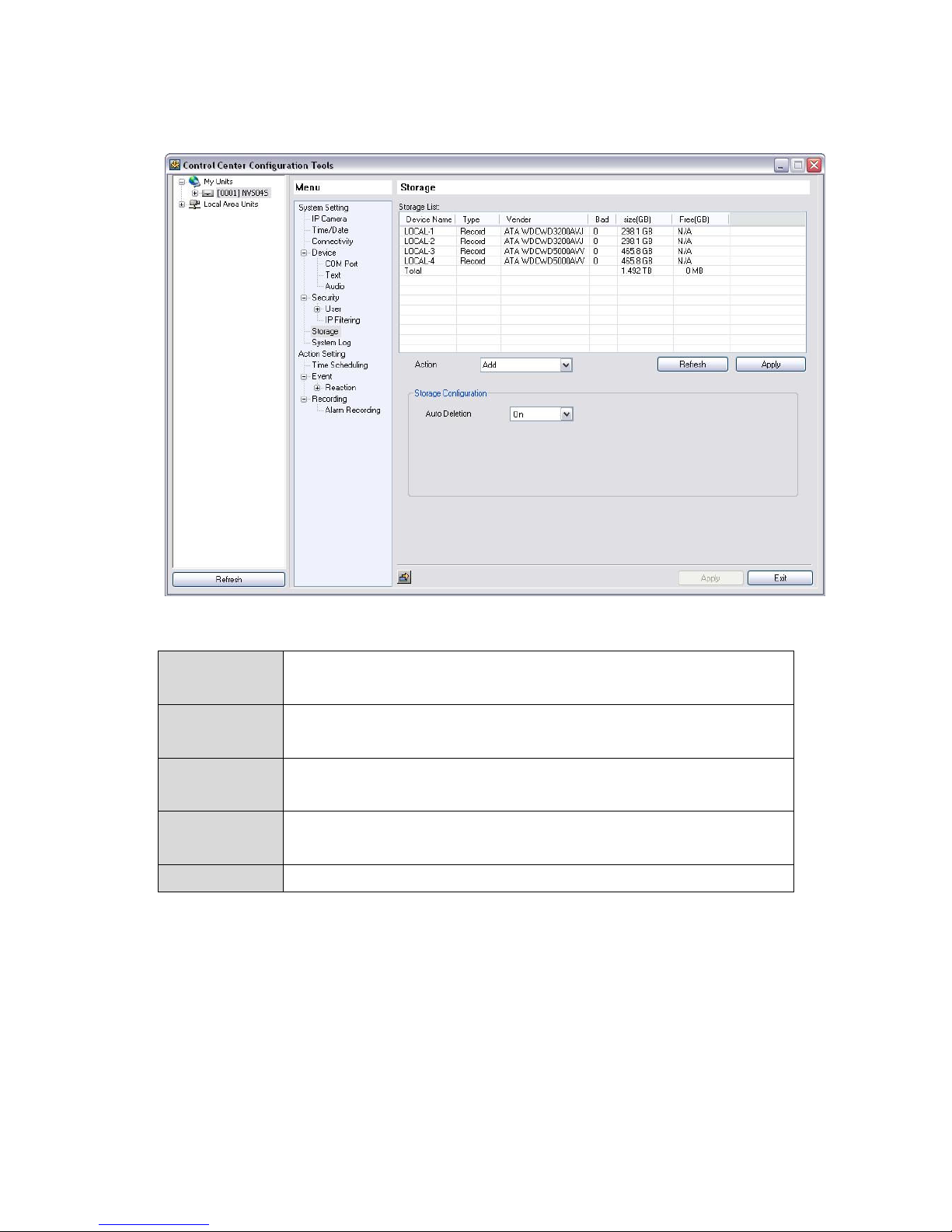
8.2.5.11. Storage
NVS04S indicates the data of total size & free size of HDD.
- Add Add Disk. Must use empty HDD not having partition table.
Partition table can be removed in PC.
- Add Used Add the used HDD without format.
<File system compatibility> can use the used HDD without deletion by "Add Used".
- Removed Remove the currently using HDD in logically. later, using "Add used" commend can
use it again without format.
- Confirm Removed Complete removal from the lists when it remains in the list after HDD removal from
NVS04S.
- Auto Deletion When no space in HDD, delete recorded data automatically.
Page 42
42
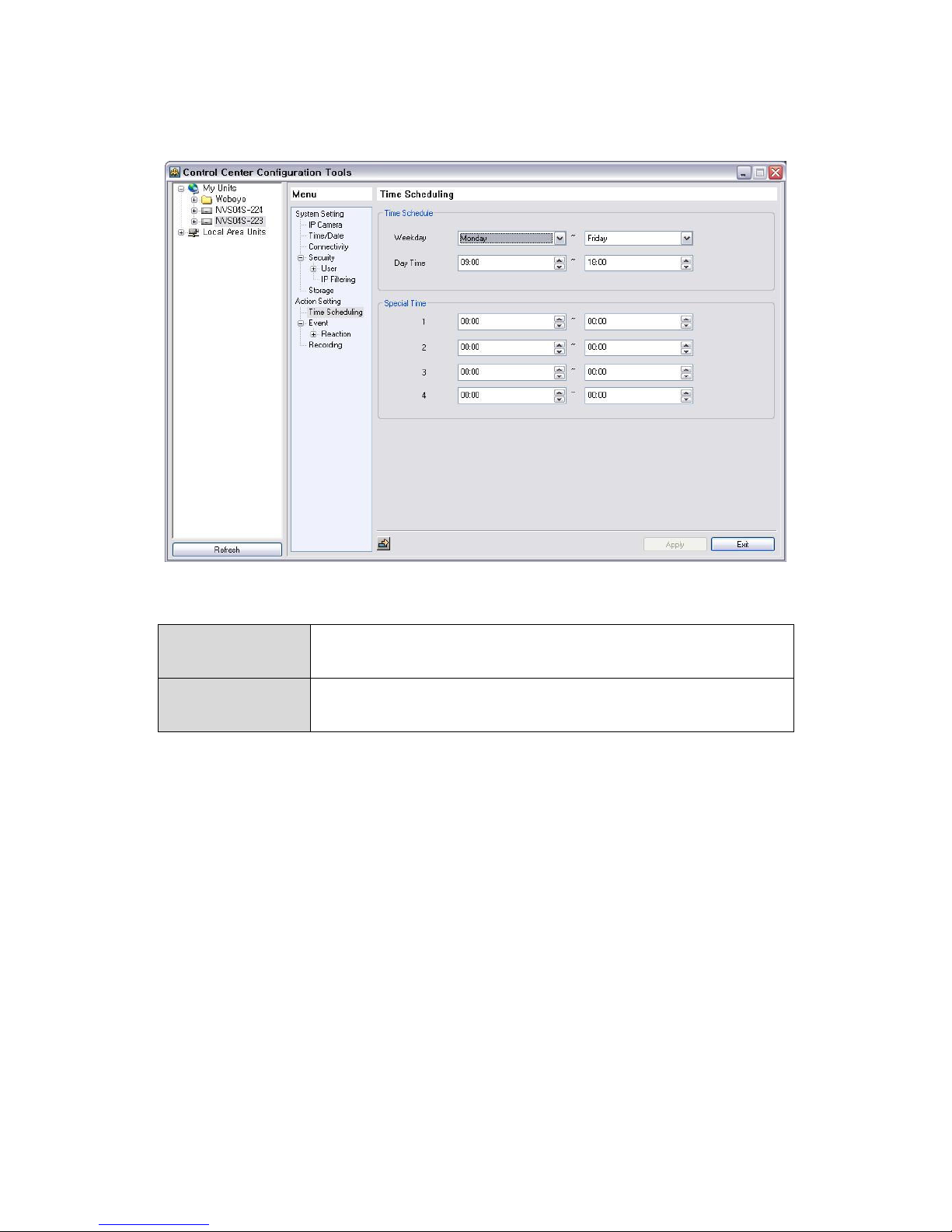
8.2.5.12. Setting Time Schedule
8.2.5.12.1. Setting Time Schedule
- Weekday : Sets start point and end point of weekday, the remaining day is automatically
included in weekend.
- Day time : Set start point and end point of day, the remaining hour is automatically
included in night
8.2.5.12.2. Setting Special Time
User can set time zone at one’s direction. User can set maximum 4 time zones.
Page 43
43
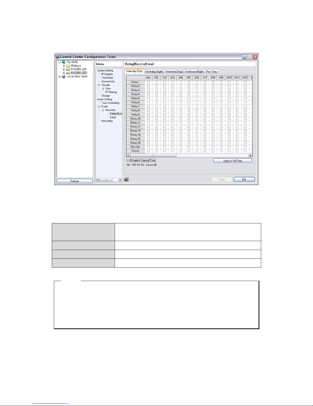
8.2.5.13. Relay/Buzzer/Email
NVS04S has 4 relay out. User can operate relay out relating to sensor input, motion detection. Relay out
can be set four time section. (weekday, weekend, day, night)
- Time Schedule : User can set four time section such as Weekday(Day), Weekday(Night),
Weekend(Day), Weekend(Night).
- Relay Source : Selects event source. (MD1~MD16, S1~S16)
- Disable in Special Time : Selects it when user does not want relay out to operate.
- Relay Post Time : Decides relay post time after events. (1 ~ 3600 second)
<ote>
1. User can set time zone in “Time Schedule” page.
2. Special time can be set maximum 4. Set up is done in “Time Schedule” page.
3. User can remove the relay in hand in such a Webpage, in this case, user get the priority against
schedule operation.
4. Event source,MD and Sensor, can be configured in each IP camear.
Page 44
44
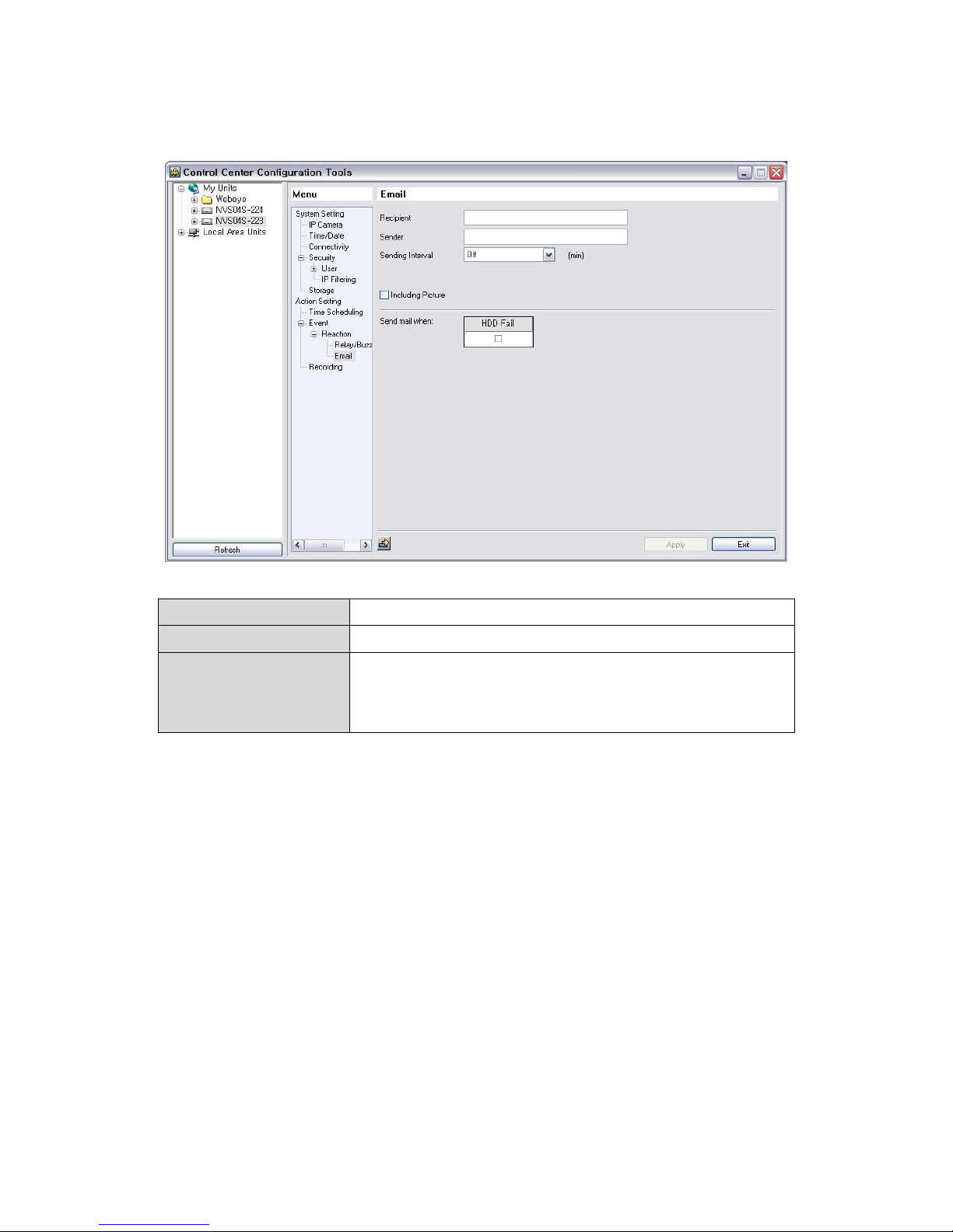
8.2.5.14. Email
- Recipient : Input E-mail address to inform Alarm
- Sender : Input “Sender” address in the typr of who@where.
- Sending Interval : E-mail notification is to send message in terms of Mail Duration set,
but not every time that Alarm is occurred. It can be set from 1 to 30
minutes.
Page 45
45
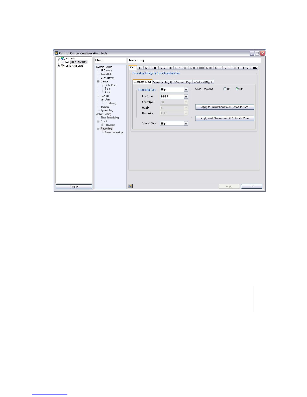
8.2.5.15. Recording
Set recording options according to each channel.
Set resolution and recording speed in the designated time zone (weekday day/ weekday night/ weekend
day/ weekend night) by using Recording group setting value. At this time user can set other recording
way of Special Time and set whether to use designated recording way in Alarm Recording group when
alarm is occurred (Alarm Recording ON/OFF).
Set resolution and recording speed by using Alarm Recording group setting value when event is occurred
and set how many seconds to record image after/before event.
<ote>
1. User can set time zone in “Time Scheduling” page.
2. Special time can be set maximum 4. Setting is done in “Time Scheduling” page.
Page 46
46
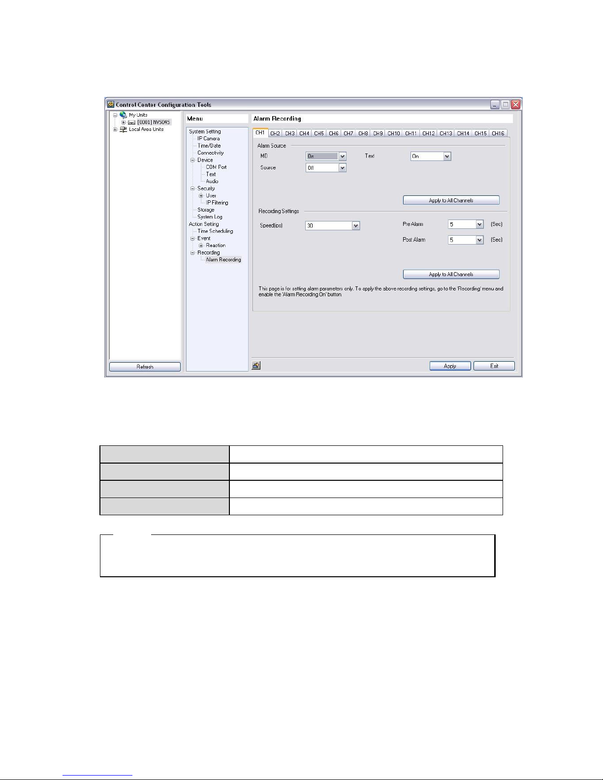
8.2.5.16. Alarm Recording
This menu is to set Alarm Recording condition. After setup Recording condition, “Alarm recording”
menu from “Recording” must be “On” to setup Alarm recording in NVS. Also, before setup Alarm
recording, “Alarm Source” must be set.
- Alarm Source : Through Alarm Source, Sensors and MD, Text input is selectable.
- Recording Speed : Available to set 1 ~ 30ips.
- Pre Alarm (sec) : It can set max. 5 second.
- Post Alarm (sec) : It can set max. 60 seconds.
<ote>
1. Please set ‘Alarm Source’ with connecting IP camera in each channel before setting of ‘Alarm
Record’. (MD, Sensor)
Page 47
47
9. Web Viewer
WebViewer is Web application program loaded to monitor real-time image or to minitor the images
recorded through Web browser to PC located remotely.
WebViewer is divided into Login page and Monitor to do monitoring real-time images, Playback to replay
reocorded images.
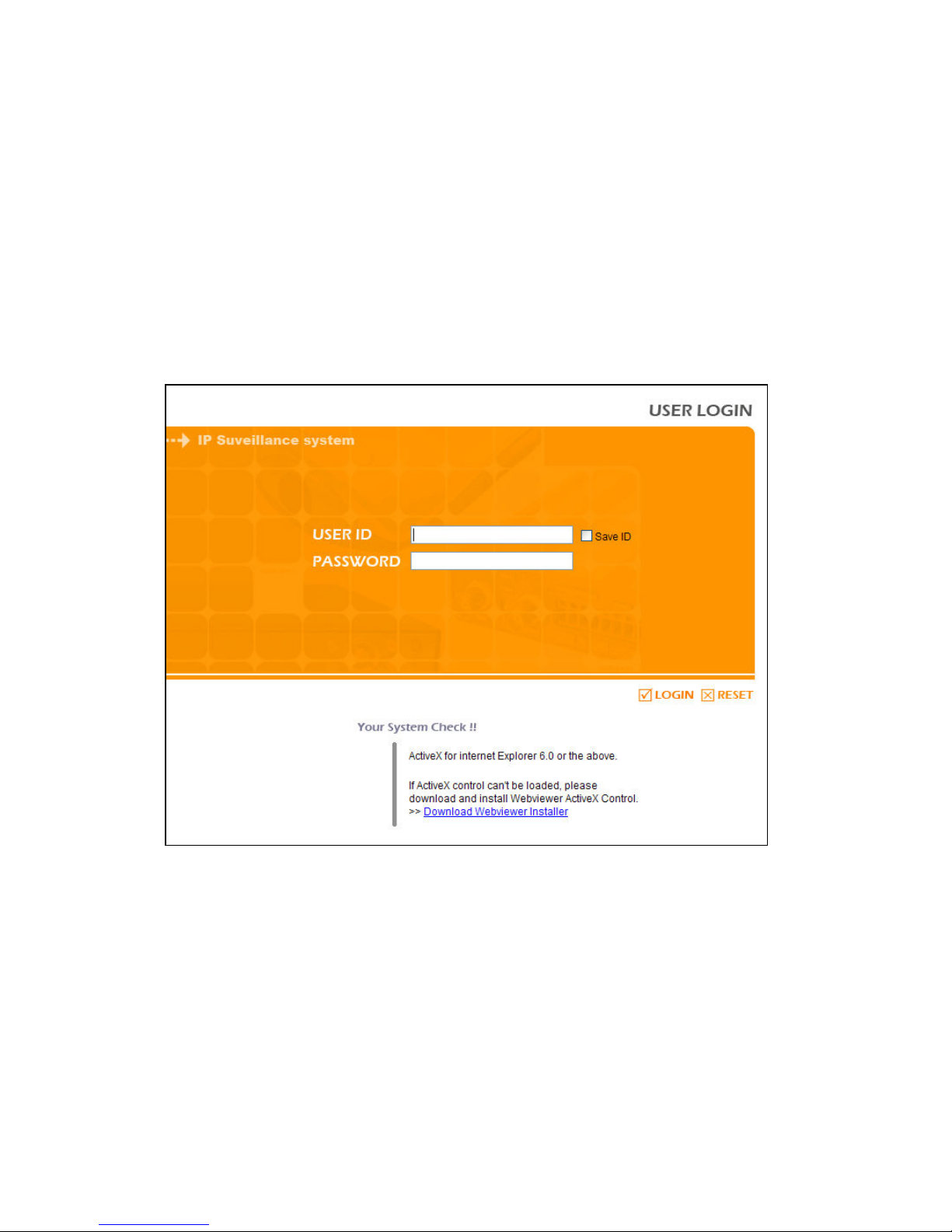
9.1. LOGI
After input IP address that set to system, then WebViewer Login page will be connected.
Input the set of User ID & Password, click ‘LOGIN’ to access.
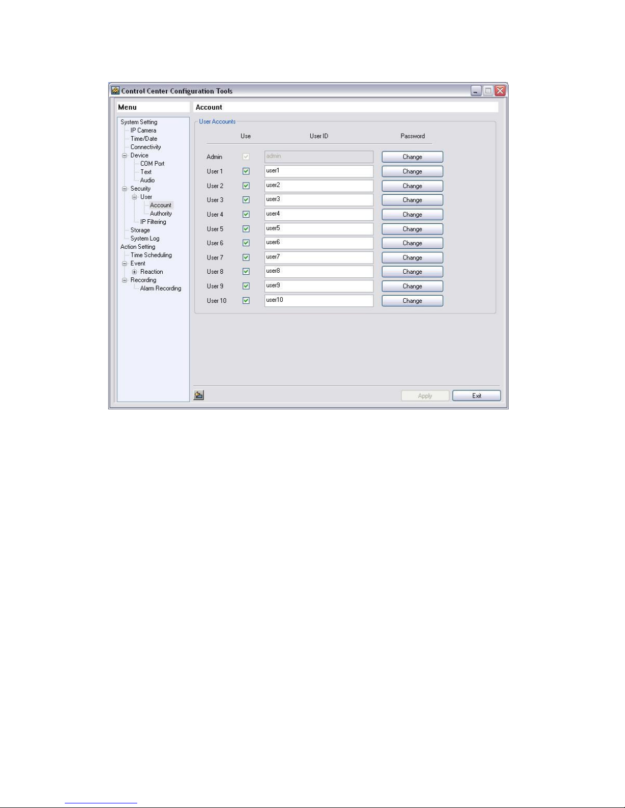
9.1. User Connection setup
To login WebViewer, input ID & Password of user that set to Configuration Tool program of Control
Center.
Page 48
48
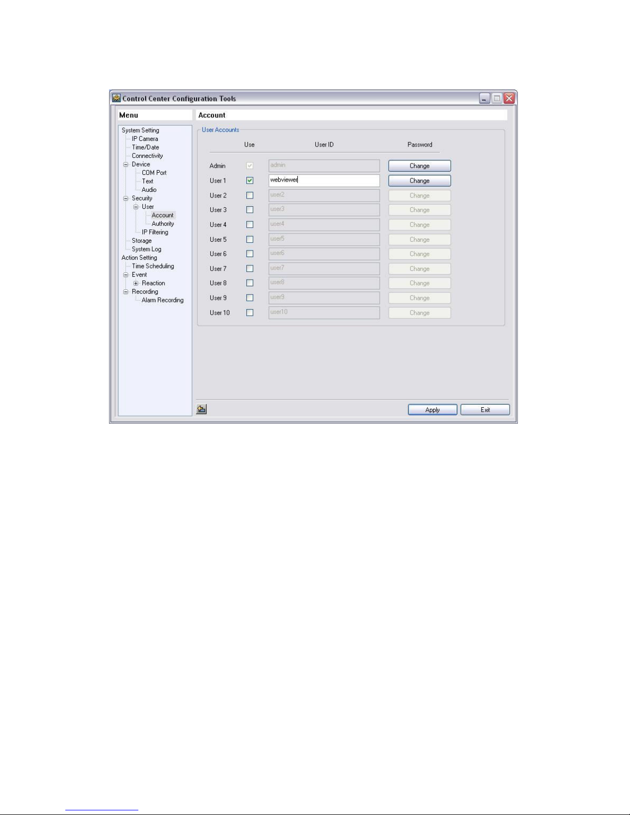
It can use total 11 ID including administrator & general user.
For the security, change ID & Password of admistrator. For the unused user’s account, it cancels the check
of’Use’ part.
Page 49
49
This is the changed ID & Passwork at Control Center Configuration Tool.
Page 50
50
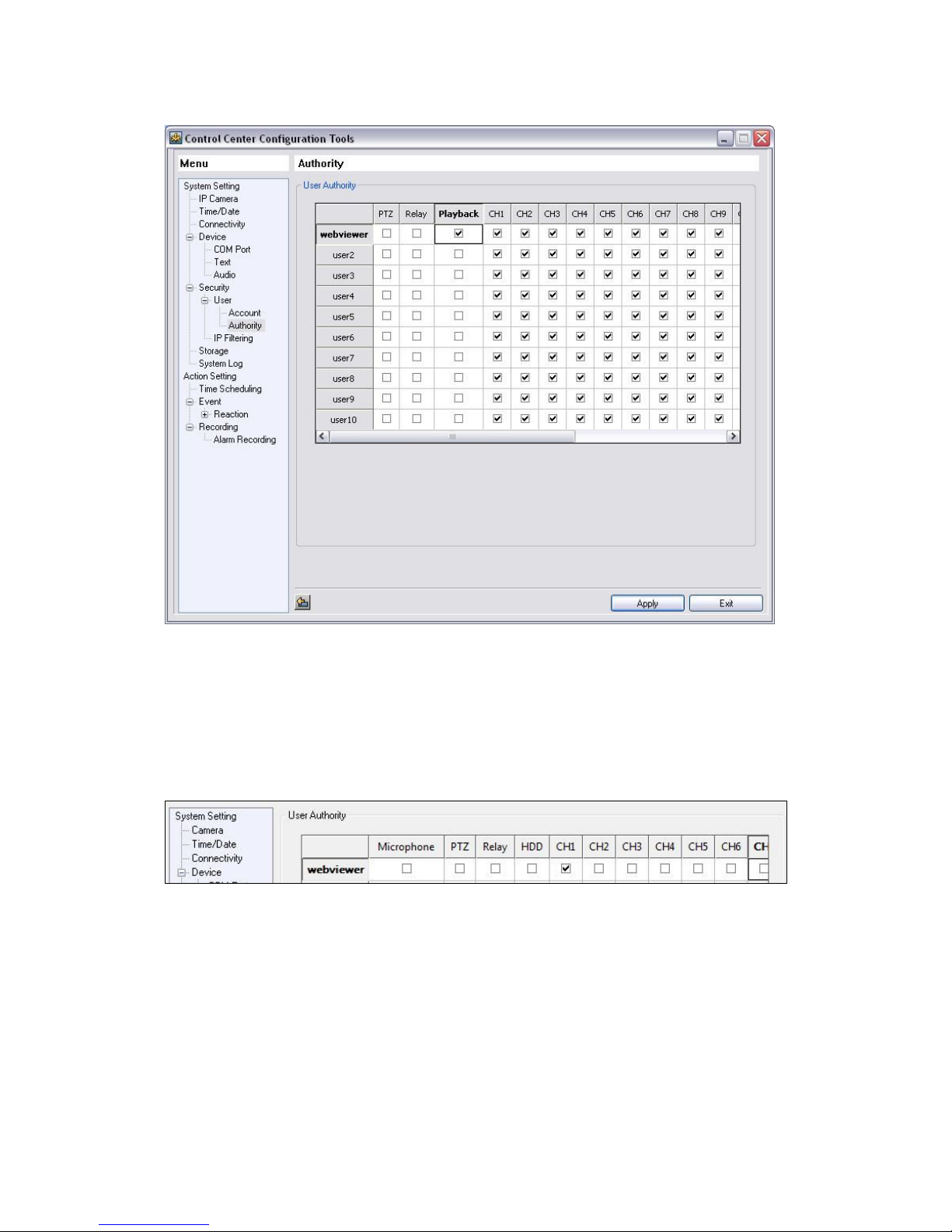
After complete of account setup, setup authorities of user’s ID.
To use Playback page, check ‘HDD’ in User’s account at Authority of Configuration Tool.
Also, click to Check box and Apply to use ‘Microphone’, ‘PTZ’, ‘Relay’ by user wanted.
If it shows 1CH image only, check CH 1 and uncheck the rest channel and function.
9.2. Usable Browser
WebViewer is optimized to Windows Internet Explorer 6.0 or higher in PC for smooth use.
Webviewer Installer
We are providing with manual installation program for WebViewer in Login page.
When accessing Webviewer at first time, user should install ActiveX to use WebViewer function.
If the installation has any problem, please, download and install it manually with the installation file
Page 51
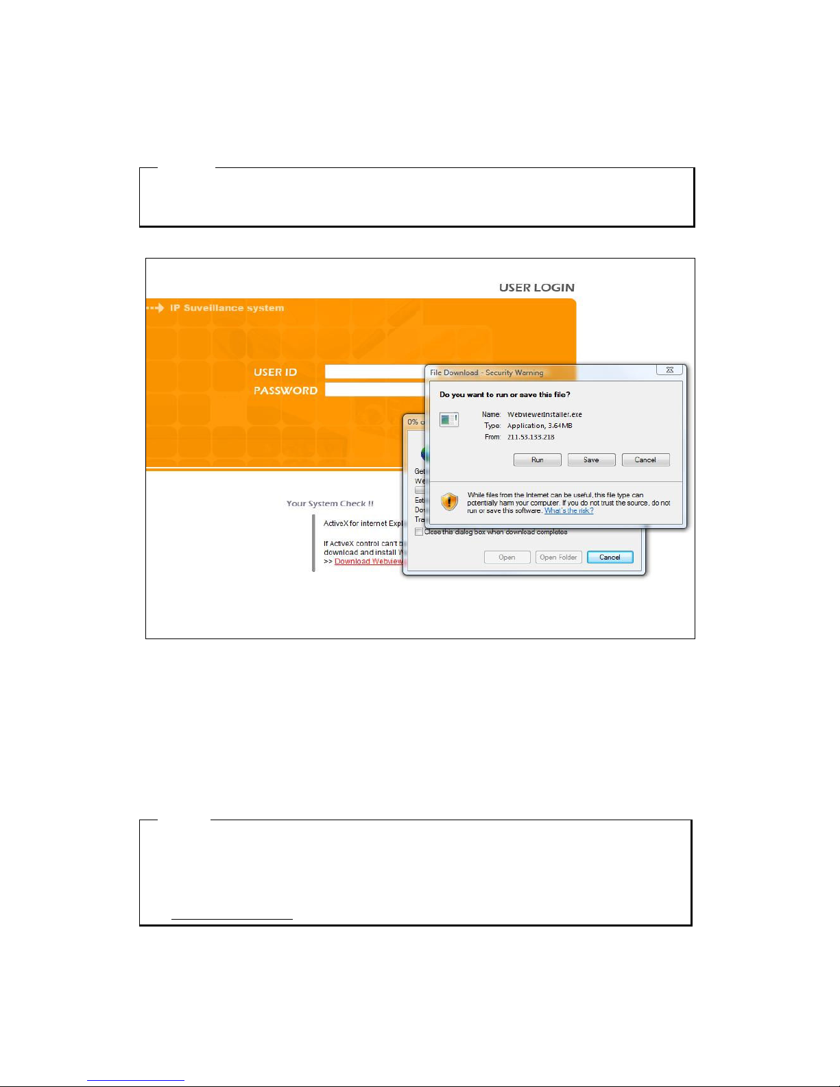
51
provided from Login pape or Webviewerinstaller.exe file from the enclosed Setup CD.
<ote>
When install WebViewer Installer, it must close all program related to Control Center. It might not be
efficient to install.
If execute Webviewerinstaller.exe file downloaded, it can use WebViewer function normally.
Save ID
Select Save ID at check box, it is to connect same User ID at next connection automatically. It is applied
to a PC that Save ID is activated.
<ote>
In case of Port changed, when access to Web Viewer, IP address and Port should be input.
Ex.) In case of Port changed to 6000
http://192.168.0.1:6000
Page 52
52
9.3. Monitor
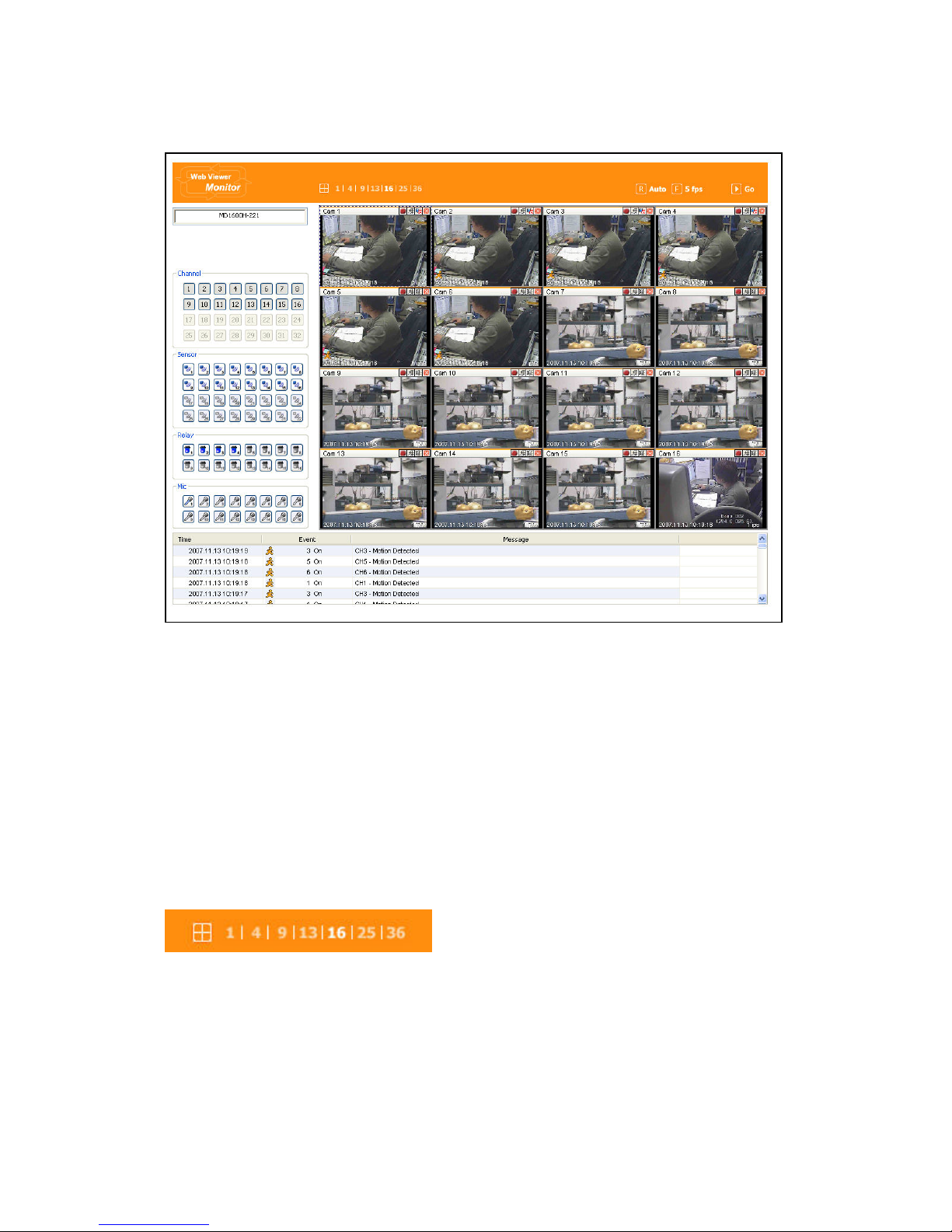
When it is authorized with User ID & Password input at Login page, it moves to Monitor page. At
Monitor page, monitor real time image of cameras connected to NVS, or it can control PTZ camera,
Relay, and use Microphone function according to user’s authorization.
Study introduction of each Monitor part and functions of the page.
9.3.1. Screen division & Change of video location
When access to first Monitor page, it is displayed into 9 division, 16divisions or 32 divisions according to
number of channel.
It can to change to 1, 4, 9, 13, 16, 25, 36 divisions by click number on top of page.
Also, it can change to 1 channel mode by click any one of channel image.
Page 53
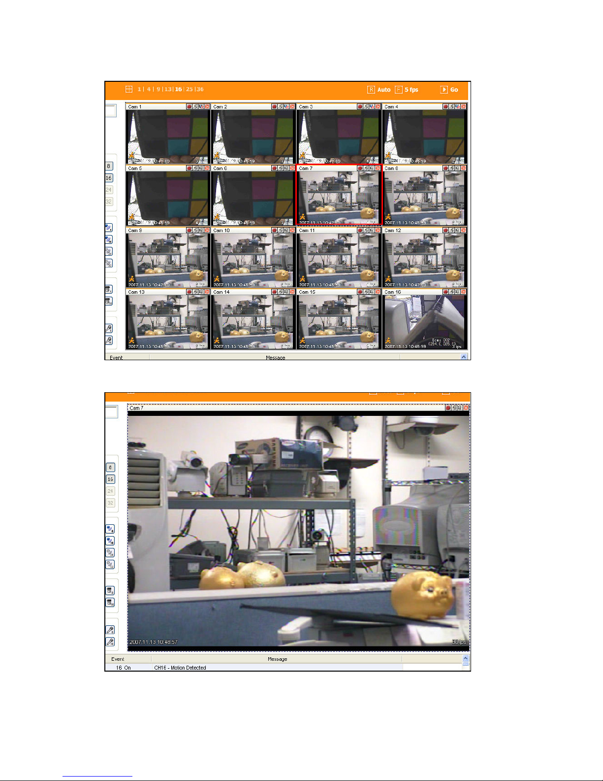
53
Double click on one of the playback screen to convert in 1 channel mode.
After conversion to 1channel mode, double click on screen to return to previous division channels.
Page 54
54
At division screen, it can change screen location.
If 3channel image moves to 6ch, drag 3ch image and drop on 6ch location so as to exchange between 3ch
and 6ch image.
9.3.2. Caption
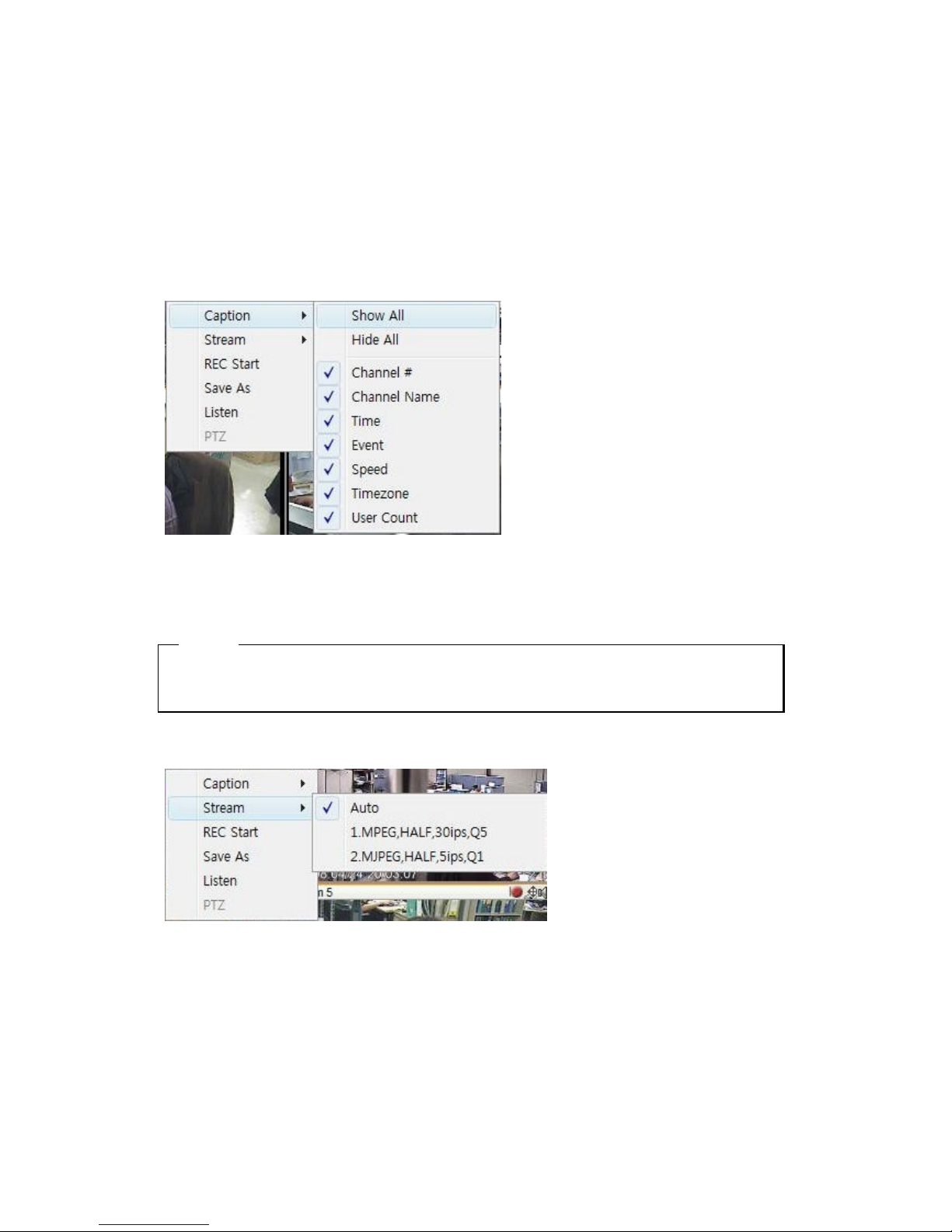
If the user click on the right button of the mouse, above menu pops up. Select “Caption” and choose the
sub menu what user wants to select, the information of Caption prints out.
<ote>
1. The image size is not changed while the resolution is changed. Its size is changed by screen division
selection from small size to big size.
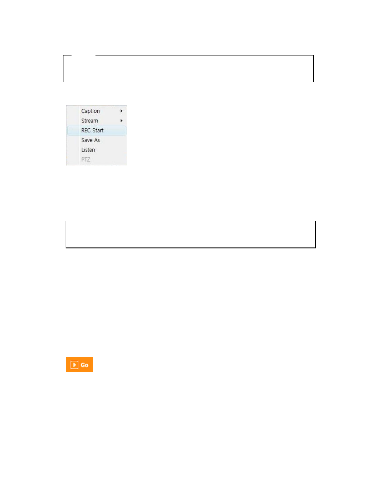
9.3.3. Stream
Select “Stream” at pop-up menu and select the stream what the user wants and it works. This stream
information is decided by schedule recording configuration. For example, the user configures schedule
recording setting to Full(Resoluion), 30ips(Speed), Q6(quality), it is set up as below,
Stream 1 : MPEG,,FULL,30ips,Q6
Stream 2 : MPEG,QCIF,30ips,Q6
Page 55
55
<ote>
The transmission of stream speed can be differentiated by network speed connected to the device and
the specificaiont and speed of the PC connected from remote site.
9.3.4. Rec Start
Select “Rec Start” at pop-up menu and it starts recording by showing “REC 00:01” at right hand side of
the bottom. Select “Rec Stop” at pop-up menu to finish recording. And a dialogue box pops up that saves
recording file.
<ote>
The file format is re4, and the user can play it using MiniPlayer. The maximum recording hours to
record in one re4 file is 10 minutes.
9.3.5. Stop motion saving (Save As)
Select “Save As File” at pop-up menu and the stop image can be saved as bmp or eye file.
9.3.6. Audio play (Listen)
When audio connected to channel is configured, press right mouse button and activate “Listen” at pop up
menu or audio play button is activated. It is the Mute status in initial stage and the user can change its
status and volume control.
9.3.7. Moving Playback
Move to Playback page by click the menu as above picture on top of page.
Page 56
56
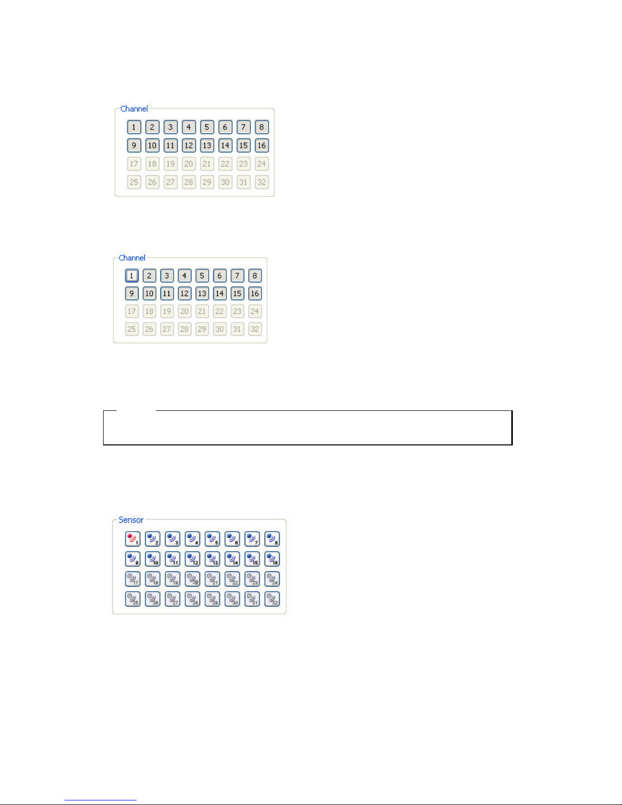
9.3.8. Channel On/Off
It is On/Off button for the Channel located to left in page. Click the channel wanted to On or Off.
And Default is On.
Above picture refer to Off channel 1. In case of Channel Off, relevant button is projected. And video does
not come and changed to black screen.
<ote>
Disabled channel button refers to do not support and relate to this unit.
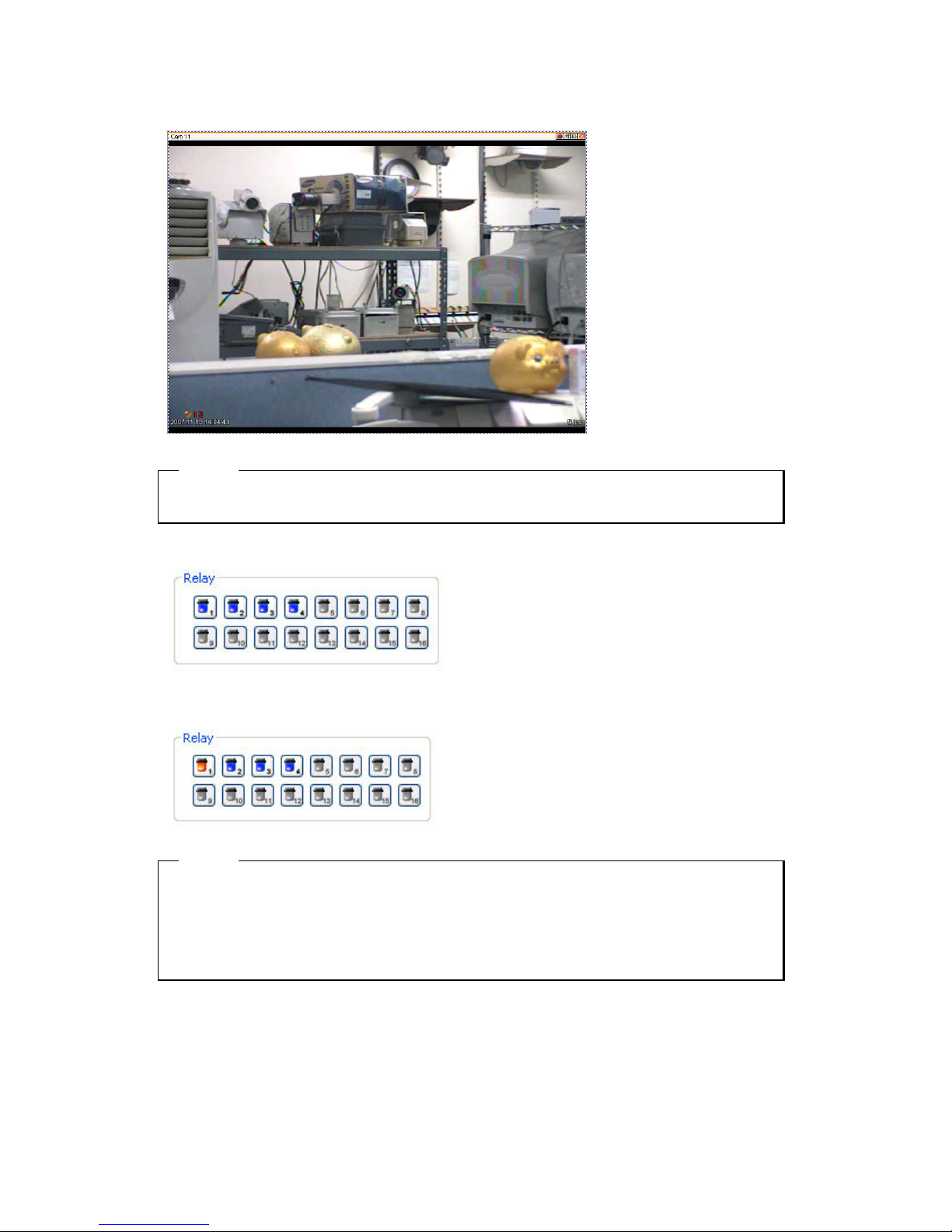
9.3.9. Sensor Indication
The icon indicates when sensor occurs in system.
When it sensorsed, relevant sensor icon comes to Red, and indicates sensor number of video.
Page 57
57
<ote>
Disabled sensor button refers to do not support and relate to this unit.
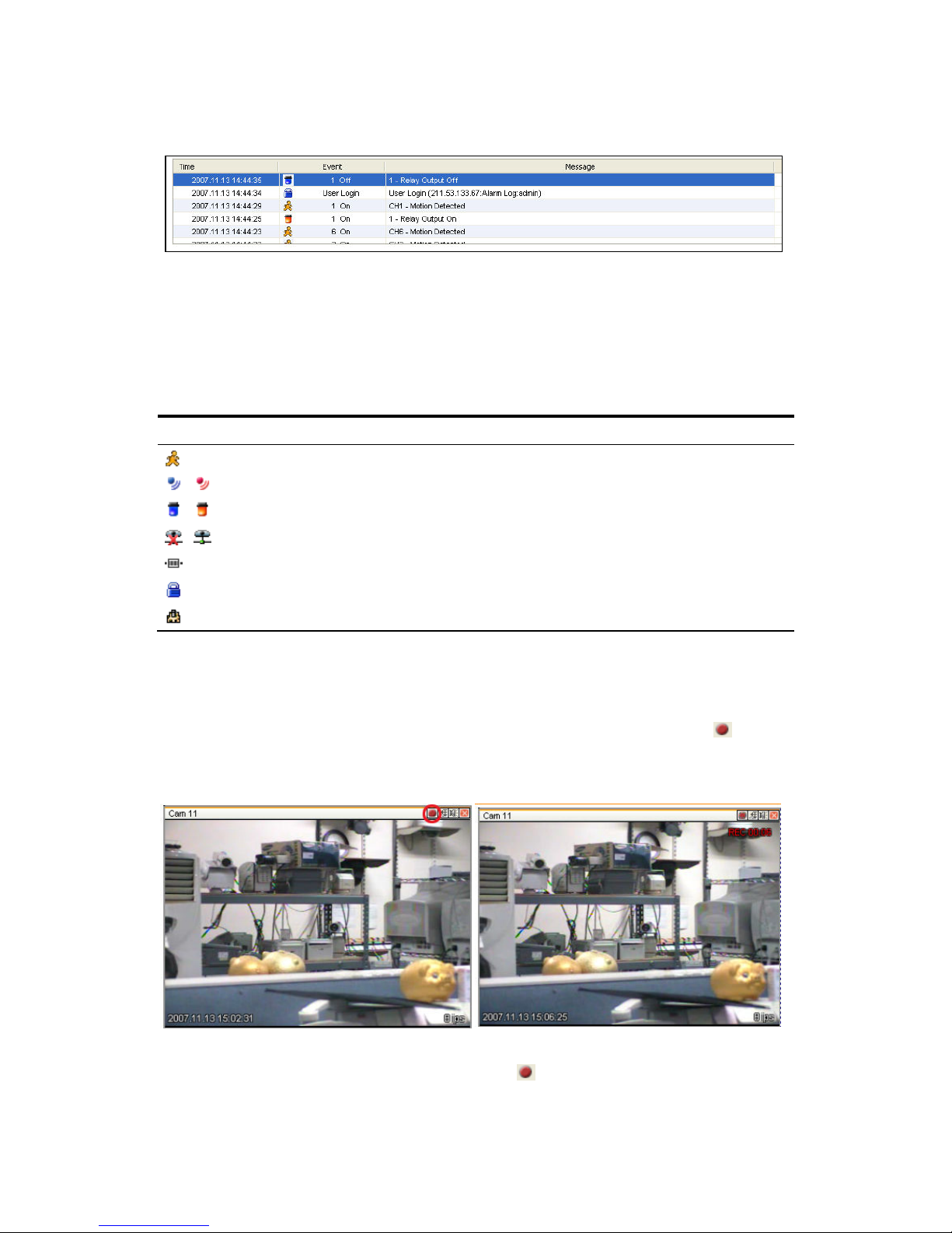
9.3.10. Relay Operation
It can On or Off Relay of the unit. Click the number button to activate Ralay On, then the incon changes
from Blue to Orange color.
<ote>
Disabled Relay button refers to do not support and relate to this unit.
Relay is need user’s authority. Refer to user manual in the unit for the setup of User’s authority of
Relay..
Page 58
58
9.3.11. Event data
It shows real time event data occurred at the bottom of monitoring page.
Indicated Event data list are as follow.
(Table. Event Icon)
Button Function
Motion Detect On
,
Sensor Input
,
Relay Output On
,
No Video, Video Detected
Text Input
User Login
Configuration Changed
9.3.12. Video Recording & recording Pause Video
9.3.12.1. Video Recording
During monitoring, it can record max. 10 minutes of video by click Quick Recording button “
”. During
Quick Recording, recording time is indicated on video.
During video recording, if click Quick Recording button “ ” to stop recording and open the dialogue
Page 59
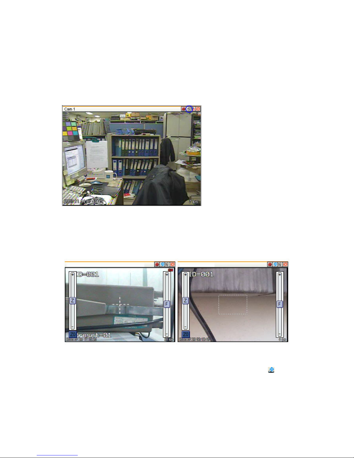
59
box to store recorded files. At this time, user can save it to the directory with any file name by user.
Saved recording file is saved into “*.re4” file format. re4 file can playback through Control Center
Playback program or Mini Player program.
9.3.13. Using PTZ
Among the icon on top of video on monitoring, click ‘PTZ’ to acitivate interfacing to control Pan, Tilt,
Zoom, and Focus. But, when PTZ camera is connected and ready to set PTZ, the button is acitavated to
use the functions.
Pan, Tilt Control
Mouse is on the image and click right button to pop-up menu for the selection or “PTZ” or
button.
Then it show Cross line on the middle of screen and click image to operate Pan, Tilt. At the middle click
Left/Right direction to control Pan, and Click Up/Down direction to control Tilt. Click as far from the
middle to activate Pan/Tilt faster.
Page 60

60
Zoom, Focus Control
Move mouse to the edge of left & right to see slide bar for Zoom, Focus.
The unit Area Zoom In available has Zoom Zero operating button. It can Zoom In/Out using slide bar at
left of image, left slide bar can control Focus.
Moving Preset
In case of Preset set, Mouse on image press right button for pop-up menu and “Goto Preset” is indicated
additionally. When select Preset list, it moves to Preset position selected. Preset should be set up by user
in advance.
Activating Auxiliary
In case of Preset set, “Auxiliary” is indicated additionally, and it operates action when select registered
menu.
Group mode
In case Group mode set to use, if PTZ enable, it signs『GM』at top right of screen which means the
status of operating of Group mode.
Area Zoom In Control
In case of Connect and set PTZ cameras that supports Area Zoom In, it is usable relevant functions. A
dotted quadrangle is shown. And it is the mode to selects the specific area with dragging mouse for
operation of Pan, Tilt, and Zoom automatically, based on the location of relevant area. To change normal
PTZ mode, press right mouse button on the image for menu pop-up, then select “Normal PTZ Mode” to
convert normal PTZ mode.
<ote>
Refer to ‘PTZ Setup’ list for PTZ camera list and PTZ setup.
Conntact to local supplier for the cameras that support Area Zoom In.
Page 61
61
9.3.13.1. Using Audio
In case of Channel setup sync with Audio, press right mouse button on the image to activate pop-up menu
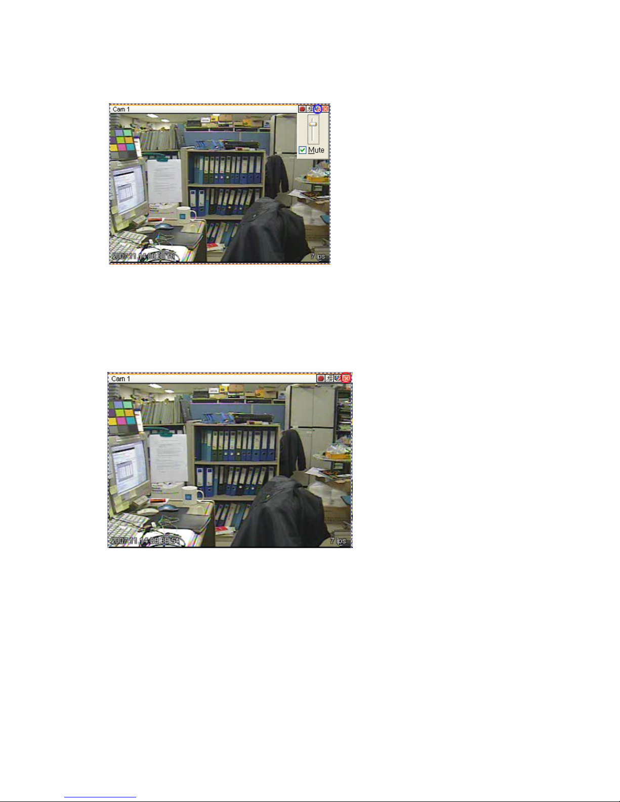
to “Listen” or activate Audio listen button. First default is Mute. In case of listening Audio, select pop-up
menu or button. After cancelling mute, control audio volume. It can mix several channels of audio.
9.3.14. Closing Video Channel
Cancel for disconnection of image monitoring by click ‘Close’ at top right on screen, then it comes to
black screen.
To reconnect the channel disconnected, it can reconnect relevant channel using ‘Channel On/Off’ menu.
Page 62
62
9.4. Playback
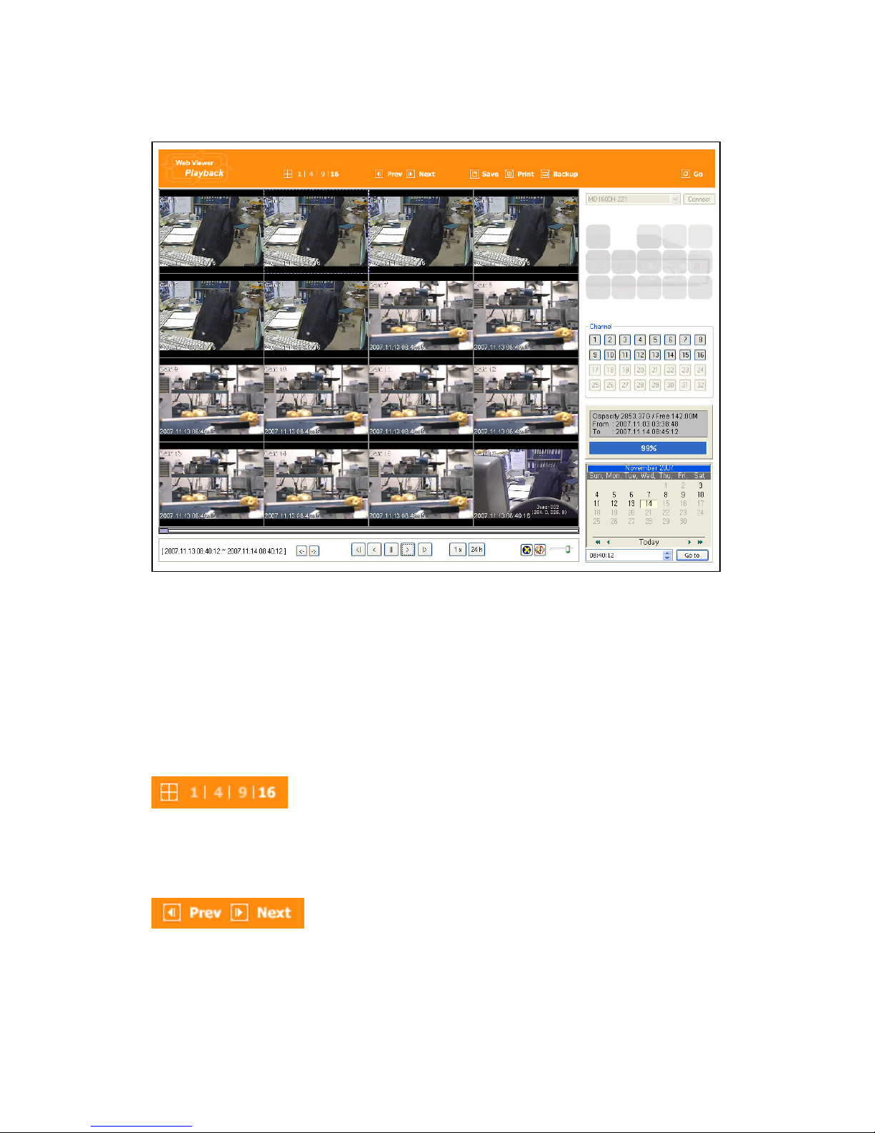
This page is to playback recorded images, and user who has authority of ‘HDD’ among user ID or
administrator can use this function.
Playback that is made up 16 divisions can play the images by searching through calander by recording
period and moving the period. It can backup recorded image and also print Pause image or save to Bmp
file.
9.4.1. Video Division & Changing Channel
Playback supports 1, 4, 9, and 16 divisional screens. It can select division using menu on tip of page as
above picture. 32ch DVR can call the channel using Group moving button as follow.
If screen shows 4 divisions CH1~CH4 and look for next CH5~CH8, it can change the channel with click
‘Next’ button. Press ‘Prev’ button to call for previous channel group CH1~CH4.
Page 63
63
9.4.2. Image recording
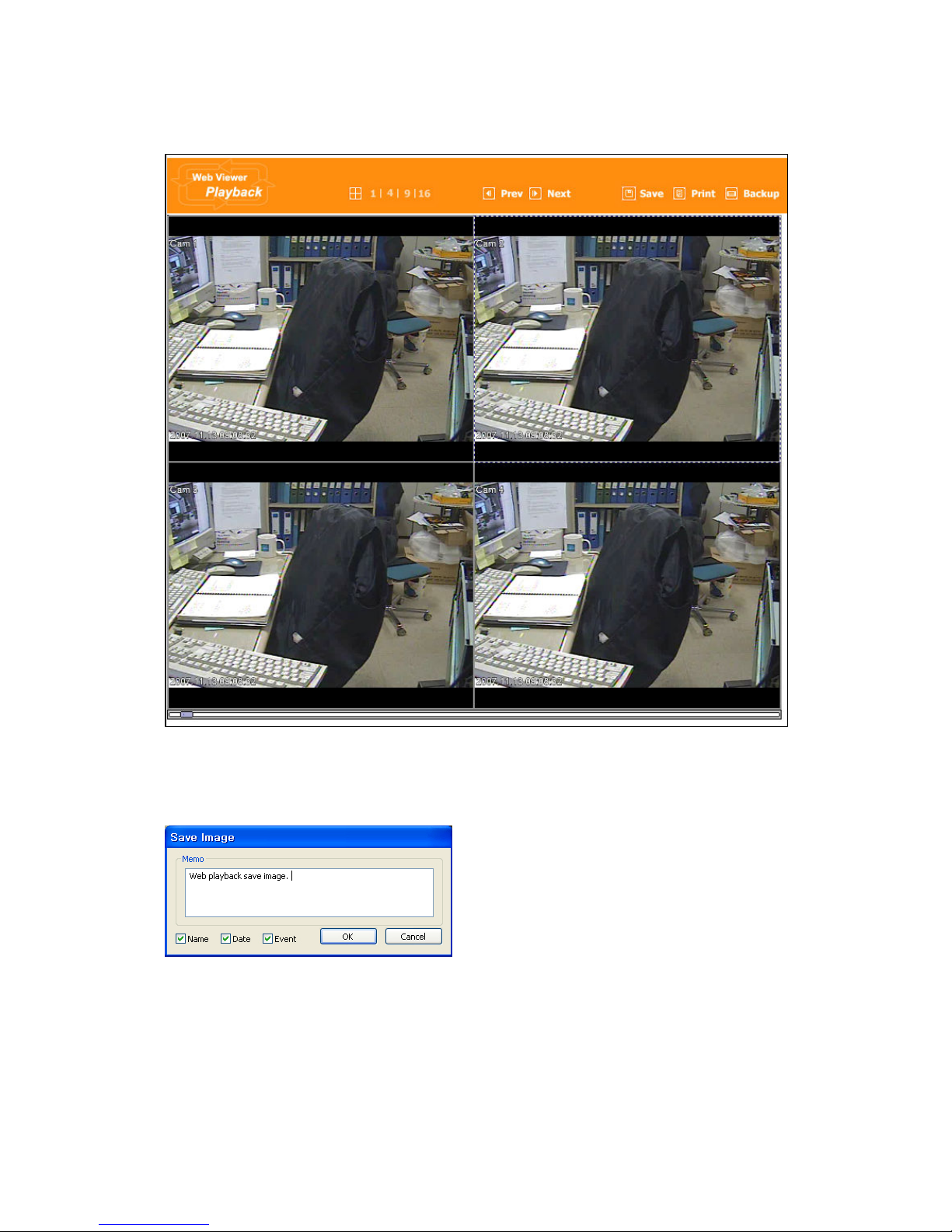
It can save playback image to BMP file.
Click mouse to channel to save. Dotted line will be surrounding to the selected channel, and click ‘Save’
button.
Save Iamge dialog box appears, then it can input message or select channel name, date, event data.
Press ‘OK’ to open dialog box for the saving location, then save bmp file.
9.4.3. Printing
Select image with mouse for the channel to print image saved, and then click ‘Print’ button.
Page 64
64
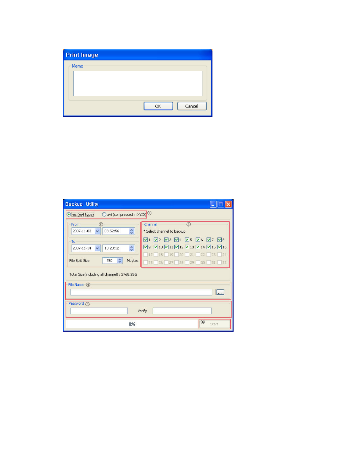
Window comes to input Memo, and click ‘OK’ button to print the image through the printer connected.
Print material includes ‘Printing Date’, ‘Channel name’, ‘Recording Date’ ‘Event’, ‘Memo’.
9.4.4. Backup
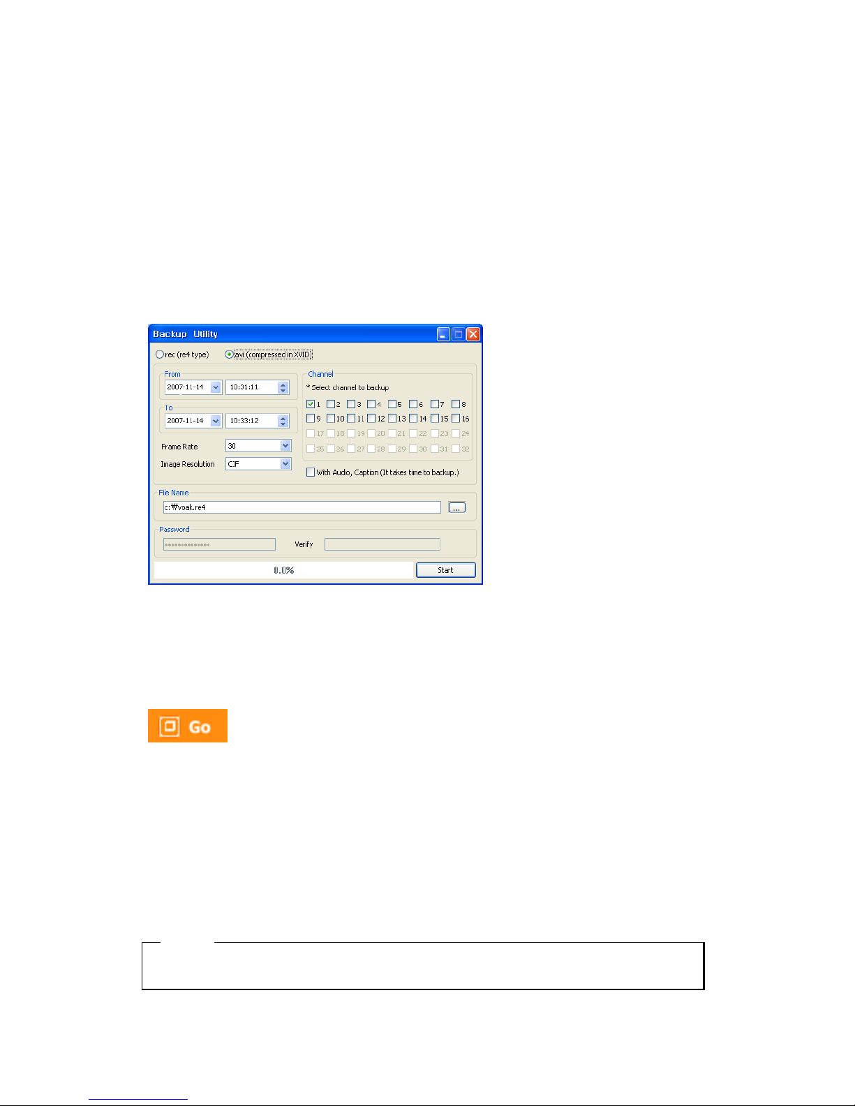
It can save recorded iamge to PC in avi or rec format by channel.
① Indicate file format to backup. In case of backup in .rec file, it can play through Control Center
Playback program or Miniplayer. And XVID codec is needed in PC playing in case of .avi file
back up.
Re4 backup can backup all channels simultaneously, and avi backup can do one channel only at
once.
② It can select recording time to backup. File Split Size divides the file to the set value in case of
over limits of the capacity set. Input range of File Split Size is from 10 to 2,048.
Page 65
65
After completion of recording time selection, total size comes. This is total size for recording,
and shows approximate size on the basis of all channels’ backup. Even if it makes for 1channel
only, it shows the total channel base.
③ It can sekect backup channel. When avi backup, it can select 1 channel only.
④ Input the location & file name to save or select folder through button, and input name.
⑤ It can input password backup file, max. 14 digits.
⑥ After select backup file format and channel, recording time, press ‘Start’ button for the window
that shows the backup processing status and processing backup.
When select avi file format, File Split Size item disappears and replaced to Frame Rate setup and Image
Resolution setup item. Also it shows window the select that can includes Audio & Caption.
9.4.5. Web Monitor
Click ‘Go’ button at top of page, and it can move Web monitor page.
9.4.6. Channel On/Off
It is the same function like Channel On/Off function at Web Monitor.
It is Channel On/Off button located on right of Page, and click On or Off page for wanted channel.
Default is On.
<ote>
Disabled Channel button refers to do not support and relate to this unit.
Page 66
66
9.4.7. Saving time & Checking Rec. Capacity
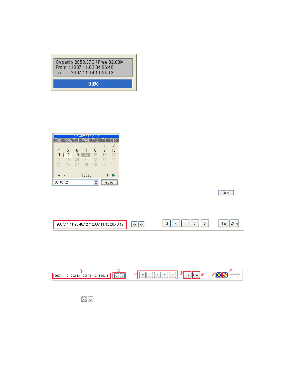
It indicates total capacity of HDD & remains and shows Starting date & Last date of recording. Also it
shows percentage (%) for HDD capacity.
9.4.8. Searching Calander
Recorded date is abled in black color, and others unrecorded date disabled in grey. Select
button after select date & time so as to playback images on the date & time selected.
When click ‘Go To’ button, it indicates for 24hours from the time selected at left bottom. As above picture,
it is possible to change the time zone with ‘24h’ button.
9.4.9. Functional function at the buttom of monitor
① Indicates playback range of recorded image.
② Press
button as the time set at (5) so as to change the time zone to playback in
forwarding and backwarding.
③ From left button, it can ‘Move a frame back’, ‘Play backward’, ‘Stop’, ‘Play’, ‘Move a frame
forward’.
④ It is the function to set play speed. After click the button, it can set the play speed ‘0.5x, 1x, 2x,
Page 67

67
4x, 16x, 32x, 64x, and All’.
⑤ It is the function to set play area. After click the button, it can select play area ‘10min, 30min,
1hour, 3hour, 6hour, 12hour, 24hour’.
⑥ It can select DirectX use or not. If check DirectX mode, it can play image into Direct Draw
based on graphic card and performance of PC.
⑦ It is the function to set audio play or not, and volume.
Page 68
68
Extension
10. HDD Replacement
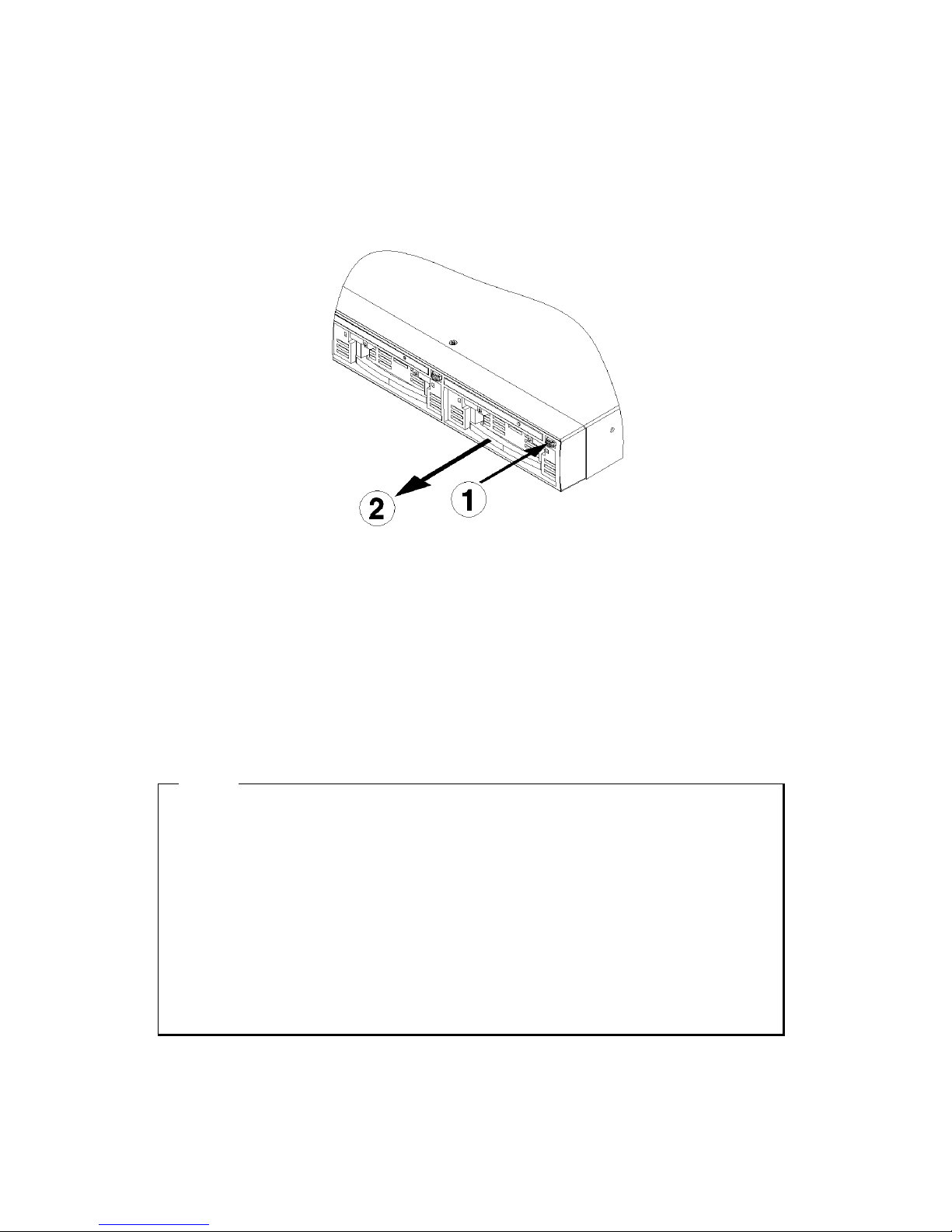
NVS04S supports Hot Swap function so, user can get rid of HDD and mount without power off.
A. Like picture, press rack removal button(①) of HDD to exchange and pull out the grip(②)
and remove the rack.
B. Mount new HDD in Rack and pull in the rack into rack mount using the grip.
C. Configuration Tool - Access to Stroage and select mounted HDD and set "Add" in
"Action" and do "Apply".
D. When all configuration are done and be out, if recording is normal, front LED of HDD will
blink. in HDD not recording, front LED is off.
<ote>
1. To use used HDD in NVS04S, please delete its HDD partition.
The way to delete partition based on Window XP, Go Control Panel-> Management Tool
->Computer Management->Storage-> Disk Management, and delete the partition.
2. When HDD disk should be exchanged, Previous disk list and Added disk list are shown at the same
time.
Please delete the Previous disk list with ‘Confirm Remove’ menu.
3. If user exchange the current working disk which is light on with Red/Green LED by turns, the disk
can be damaged physically.
In this case, exchange it after power-off.
Page 69
69
11. Cascade Configuration
11.1. Cascade Connection
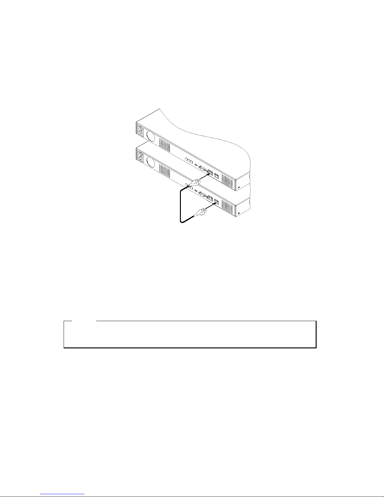
NVS04S can add Max. 8 units of NVS04R by using Cascade Port and expand up 32TB recording
capacity.
(1) Configure each different ID about NVS04R.
(2) If ID is configured, connect each NVS04R to Cascade port and Lan Port by Gigabit Ethenet cable.
예) In case of 8 ea of NVS04R,
NVS04S(Cascade) -> NVS04R-01(Lan) -> NVS04R-02(Cascade) -> NVS04R-04(LAN)
-> … NVS04R-08(LAN)
(3) Connect Private port of NVS04S to Lan port of NVS04R.
(4) After finsing above all configuration, access to Configuration Tool-Stroage and check Disk list and
then all HDD in connected NVS04S will be shown in order like the below pics.
<ote>
1. to form NVS04R by Cascade, Must use Gigabit Ehternet Cable.
2. This function will be provided later.
Page 70

70
APPENDIX
Page 71

71
#1. How to recognize manufacturing date
The manufacturing date by Webgate can be recognized by S/N(Serial Number) attached at the each
product.
S/ : Serial umber
Management number for each Webgate product to combine twelve alphabet character and digit including
model name, manufacturing year/month/week
You can see serial number by looking at the bottom of product attached label and system info of
Configuration Tool.
Serial umber Format
□ □
□ □ □ □ □ □ □ □ □ □
Year/Month
Webgate No. Webgate No.
Model Name No.
(1) 1~2 digits : Identify Model name of product
(2) 3~8, 8~12 digits : Webgate internal number
(3) 5~6 digits : Manufacturing year
(4) 7 digits: Manufacturing month
Please see the below table for manufacturing month.
Jan Feb
Mar Apr May Jun Jul Aug Sep Oct Nov Dec
1 2 3 4 5 6 7 8 9 A B C
The example of verifying manufacturing date using serial number
The below S/N can be verified as following as:
『
『『
『 D60507B22051 』』』』
(1) “D6” means “MD1600H” product
(2) “07B” means that it was manufactured on November of 2007
Page 72

72
#2. Specification
Item Description
Recording
Video(Camera) 16channel
Audio(Camera) 16channel
Log Yes
Performance
Up to 16ch@MPEG4/D1/30fps
Up to 8ch@MPEG4/720p/30fps
Input/Output
Ehternet Port(2)
1 Gb for public network
1 Gb for private network and storage expansion
RS-232C Serial port for Text input
Storage
Storage Device 4SATA interface with hot-swap function
Extension Up to 32TB with up to 8 NVS04R(late)
Intelligent File System Data-loss protection against power failure
Operation
Recording
Support Webgate network camera
Support RTSP network camera
Auto IP configuration Easy network camera install in private port
Operation System Embedded Linux
Temperature
Operation +5℃ ~ +45℃
Storage -10℃ ~ +55℃
Relative
Operation 30~80%, free of condensation
Storage 93% below, free of condensation
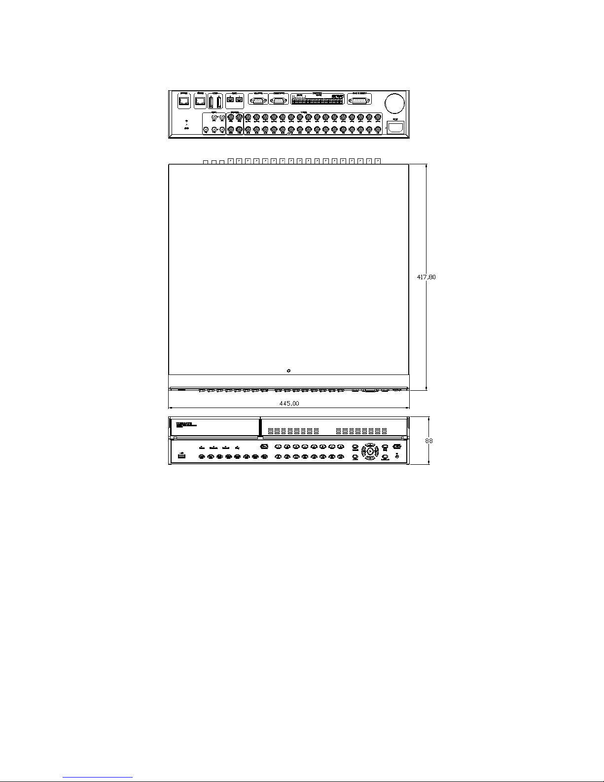
Dimensions (mm) 430(W) x 362(D) x 44(H)
Weight 5.5 kg (with one HDD)
Power Comsumption (Applied Adaptor) AC 100~240V, 50/60Hz, Max. 85W, Typical 60W
Page 73
73
Page 74

WEBGATE Inc.
6F, Hanlim Venture Town Bldg., 689-6, Geumjeong-dong, Gunpo-si,
Gyeonggi-do, Korea (435-862)
Tel : (82-31) 428-9300
Fax : (82-31) 455-3955
www.webgateinc.com
The content of this manual can differ according to firmware or Software upgrading, and the standard and
appearance of products may be changed for the improvement of quality without an advance notice
 Loading...