

Page 1

We sincerely appreciate purchasing Digital Video Recorder.
For product connection and initial configuration, please, refer to the
installation guide and for the product details, refer to user guide
English
H.264
MH1600H / MH1600M / MH3200M
Digital Video Recoder
Page 2

Installaction & User Manual
2
Introduction
Thank you for purchasing a Webgate digital video recorder.
This manual is for MH1600H, MH1600M, MH3200M.
Before product installation and operation, please become thoroughly familiar with this user
manual and other manuals referenced by this manual.
This user manual and the software and hardware described here are protected by copyright law.
With the exception of copying for general use within fair use, copying and reprinting the user
manual, either partially or in entirety, or translating it into another language without the consent
of Webgate Inc. is strictly prohibited.
This specification may change without prior notice for improvement of product performance.
Product Warranty and Limits of Responsibility
The manufacturer does not assume any responsibility concerning the sale of this product and
does not delegate any right to any third party to take any responsibility on its behalf. The
product warranty does not cover cases of accidents, negligence, alteration, misuse or abuse.
No warranty is offered for any attachments or parts not supplied by the manufacturer.
Malfunctions due to negligence by the user
Deliberate disassembly and replacement by the user
Connection of a power source other than a properly rated power source
Malfunctions caused by natural disasters (fire, flood, tidal wave, etc.)
Replacement of expendable parts (HDD, FAN, etc.)
※ The warranty period for the HDD and Fan is one year after purchase.
This product is not for exclusive use of crime prevention but for assistance in cases as
Page 3

fire or theft. We take no responsibility for damage from any incident.
Caution
As this equipment undergone EMC registration and suitable for business purpose, distributors
and users are aware of this point.
FCC Compliance Statement
Caution: Any changes or modifications in construction of this device which are not expressly
approved the party responsible for compliance could void the user's authority to operate the
equipment.
NOTE: This equipment has been tested and found to comply with the limits for a Class A
digital device, pursuant to part 15 of the FCC Rules. These limits are designed to provide
reasonable protection against harmful interference when the equipment is operated in a
commercial environment. This equipment generates, uses, and can radiate radio frequency
energy and, if not installed and used in accordance with the instruction manual, may cause
harmful interference to radio communications, Operation of this equipment in a residential
area is likely to cause harmful interference in which case the user will be required to correct
the interference at his own expense.
Warning
This is a class A product. In a domestic environment this product may cause radio interference
in which case the user may be required to take adequate measures
Warning
1. Risk of Explosion if Battery is replaced by an Incorrect Type. Dispose of Used Batteries
According to the Instructions
2. In case of changing built-in lithum battery, it should be replaced as same or kindred one to
prevent a danger of explosion. Since old batteries could be a factor of environment
contamination, be cautious to treat them.
3. Do not throw the batteries to fire or heating. Neither short circuit or disassembly is prohibited.
Page 4

Installaction & User Manual
4
4. Do not charge the batteries provided with Remote Controller
Important Notice
1. Do not place heavy objects on the top of the product.
2. This equipment is indoor use and all the communication wiring are limited to inside of the
building
3. Product is for indoor use. It is not weatherproof. Use product with referring to its
environmental specifications (Temperature & Humidity). To clean the product, gently wipe the
outside with a clean dry cloth.
4. Product uses AC power of 110V ~ 240V. Be cautious not to cause electric damages to
product.
5. Be careful not to drop the product. Physical shocks may harm the product including internal
HDD. In addition, be sure the product is secured after installation.
6. Product is made of metal. Therefore you can hurt human beings if you throw it to them or hit
on them. When installing product, be cautious to locate on safe places where children are
unreachable.
7. If Product does not operate properly, please contact the closest WEBGATE distributor for
after sales service. Tampering or disassembling the product will void the warranty.
8. Security surveillance laws may differ for each country. Therefore, please contact the local
region first to avoid any surveillance law violations.
9. "Rack Mount Instructions - The following or similar
rack-mount instructions are included with the installation instructions:
A) Elevated Operating Ambient - If installed in a closed or multi-unit rack assembly, the
operating ambient temperature of the rack environment may be greater than room ambient.
Page 5

Therefore, consideration should be given to installing the equipment in an environment
compatible with the maximum ambient temperature (Tma) specified by the manufacturer.
B) Reduced Air Flow - Installation of the equipment in a rack should be such that the amount
of air flow required for safe operation of the equipment is not compromised.
C) Mechanical Loading - Mounting of the equipment in the rack should be such that a
hazardous condition is not achieved due to uneven mechanical loading.
D) Circuit Overloading - Consideration should be given to the connection of the equipment to
the supply circuit and the effect that overloading of the circuits might have on overcurrent
protection and supply wiring. Appropriate consideration of equipment nameplate ratings
should be used when addressing this concern.
E) Reliable Earthing - Reliable earthing of rack-mounted equipment should be maintained.
Particular attention should be given to supply connections other than direct connections to
the branch circuit (e.g. use of power strips)."
Experience and technical skills are needed for the installation of this product as an improper
installation may cause fire, electric shocks, or defects. Any installation job should be performed
by the vendor you purchased this product from.
The content of this manual can differ according to firmware or Software upgrading, and the
standard and appearance of products may be changed for the improvement of quality without
an advance notice.
Page 6

Installaction & User Manual
6
Contents
Introduction ............................................................................................................................... 1
KEY FEATURES .............................................................................. 11
INSTALL MANUAL.......................................................................... 14
1. FEATURE ................................................................................. 14
1.1 Supplied Accessories .................................................................................................... 14
1.2 Description & Function .................................................................................................. 15
1.2.1 Front ...................................................................................................................... 15
1.2.2 Rear ........................................................................................................................... 17
1.2.3 REMOTE CONTROLLER ...................................................................................... 20
2. INSTALLATION ........................................................................... 22
2.1 Installation and Connection ........................................................................................... 22
2.1.1 Connecting & Running ........................................................................................... 22
2.2 Running OSD menu...................................................................................................... 24
2.2.1 OSD menu configuration ........................................................................................ 24
2.2.2 Setting remote controller ........................................................................................ 25
2.2.3 Installation examples ............................................................................................. 27
2.2.4 Basic Setting ......................................................................................................... 29
2.3 Connecting and configuring DIO ports ........................................................................... 34
2.3.1 Wire Handlin .......................................................................................................... 34
2.3.2 Inserting & removing wire....................................................................................... 34
2.3.3 Connecting and configuring sensor ........................................................................ 35
2.3.4 HDD ...................................................................................................................... 46
2.3.5 Remote monitor and control ................................................................................... 47
2.3.6 External device connection .................................................................................... 50
2.3.7 NVS04 connection ................................................................................................. 51
USER MANUAL .............................................................................. 53
Page 7

3. MENU USE .............................................................................. 53
3.1 Menu Structure ............................................................................................................. 53
3.2 Function Menu .............................................................................................................. 53
3.3 Factory Reset ............................................................................................................... 54
4. MONITORING .......................................................................... 59
4.1 Basic Screen .............................................................................................................. 59
4.2 Single Full Screen Mode ............................................................................................... 59
4.3 Multi Screen Mode ........................................................................................................ 59
4.4 Screen Description ....................................................................................................... 59
4.5 Auto Switch Mode (Sequence) ...................................................................................... 60
4.5.1 System Standard Mode .......................................................................................... 60
4.5.2 User Sequence Mode ............................................................................................ 61
4.6 Event Screen ................................................................................................................ 61
4.7 Zoom Screen Mode ...................................................................................................... 62
4.8 Pause Live Screen ....................................................................................................... 62
4.9 PTZ Control .................................................................................................................. 63
4.9.1 Pan/Tilt/Zoom ............................................................................................................. 65
4.9.2 Focus ......................................................................................................................... 65
4.9.3 Load Preset ................................................................................................................ 65
4.9.4 Save Preset ................................................................................................................ 65
4.9.5 Auxiliary On ................................................................................................................ 65
4.9.6 Auxiliary Off ................................................................................................................ 65
4.9.7 Menu .......................................................................................................................... 65
5.PLAYBACK .................................................................................. 66
5.1 Playback Mode ............................................................................................................. 66
5.1.1 Playback on Standard monitor (16 / 9 division) ....................................................... 66
Page 8

Installaction & User Manual
8
5.1.2 Playback function .................................................................................................. 66
5.2 SEARCH MODE ........................................................................................................... 67
5.2.1 Time Search .......................................................................................................... 67
5.2.2 Schedule Search ................................................................................................... 67
5.2.3 Event Search ......................................................................................................... 68
5.2.4 Thumbnail Search.................................................................................................. 69
5.3 Copy............................................................................................................................. 71
5.3.1 CD/DVD ................................................................................................................ 71
5.3.2 RE4 ....................................................................................................................... 72
5.3.3 AVI ........................................................................................................................ 74
6. CONFIGURATION ....................................................................... 75
6.1 Recording Structure ...................................................................................................... 75
6.2 System Setup ............................................................................................................... 75
6.2.1 Date/Time .............................................................................................................. 75
6.2.2 Disk ....................................................................................................................... 79
6.2.3 User Setup ............................................................................................................ 87
6.2.4 Utility ..................................................................................................................... 89
6.3 Network ........................................................................................................................ 92
6.3.1 xDSL ..................................................................................................................... 93
6.3.2 WRS ...................................................................................................................... 94
6.3.4 Notifier ................................................................................................................... 96
6.4 Device Setup ................................................................................................................ 97
6.4.1 Camera Setup ....................................................................................................... 97
6.4.2 Monitor Setup ........................................................................................................ 98
6.4.3 Audio Setup ......................................................................................................... 100
6.4.4 Text Setup ........................................................................................................... 101
6.4.5 Serial Setup ......................................................................................................... 103
6.5 Event Setup ................................................................................................................ 105
6.5.1 Event Check ........................................................................................................ 105
6.5.2 Sync Event .......................................................................................................... 106
6.5.3 Motion Detection .................................................................................................. 111
Page 9

6.5.4 Sensor ................................................................................................................. 113
6.5.5 Preset .................................................................................................................. 113
6.6 Recording setup ......................................................................................................... 114
6.6.1 Program setup ..................................................................................................... 114
6.6.2 Manual/Schedule recording setup ........................................................................ 116
7. WEB VIEWER ........................................................................... 121
7.1 System requirement.................................................................................................... 121
7.2 Login .......................................................................................................................... 122
7.3 User Setup ................................................................................................................. 123
7.4 Browser available ....................................................................................................... 123
7.5 Monitor ....................................................................................................................... 124
7.5.1 Screen division and changing video position ........................................................ 124
7.5.2 Move to Playback ................................................................................................ 125
7.5.3 Channel On/Off .................................................................................................... 126
7.5.4 Sensor Indication ................................................................................................. 126
7.5.5 Relay operation ................................................................................................... 126
7.5.6 Using Microphone ................................................................................................ 126
7.5.7 Event Data........................................................................................................... 127
7.5.8 Video Recording & Save Saving .......................................................................... 127
7.5.9 Using PTZ ........................................................................................................... 128
7.5.10 Using Audio ......................................................................................................... 129
7.5.11 Closing Video Channel ........................................................................................ 129
7.6 Playback..................................................................................................................... 130
7.6.1 Video Division & Changing Channel ..................................................................... 130
7.6.2 Image recording ................................................................................................... 130
7.6.3 Print..................................................................................................................... 131
7.6.4 Backup ................................................................................................................ 131
7.6.5 Web Monitor ........................................................................................................ 132
7.6.6 Channel On/Off .................................................................................................... 132
7.6.7 Saving time & Checking Rec, Capacity ................................................................ 132
7.6.8 Searching Calander ............................................................................................. 132
Page 10

Installaction & User Manual
10
7.6.9 Functional function at the bottom of monitor ......................................................... 133
8 JAVA VIEWER .......................................................................... 134
9 USER MANUAL FOR MOBILE VIEWER ................................ 135
9.1 Log-In page ................................................................................................................ 135
9.2 Monitoring page .......................................................................................................... 135
TROUBLE SHOOTING ................................................................. 137
THE WAY TO CHECK THE MANUFACTURING DATE ............... 139
AVAILABLE HDD .......................................................................... 140
COMPATIBLE CD/DVD LIST ........................................................ 140
SPECIFICATION............................................................................ 140
PRODUCT DIMENSION ................................................................ 143
Page 11

KEY FEATURES
Monitoring Screen
Supports real live video with high resolution per each channel and variable display mode.
Real H.264 Video
Various monitoring
Single, 4ch, 9ch, 10ch, 16ch
Auto Switching(AUTO)
Composite 4 ea, DVI 2ea
Audio Recording
Supports real-time audio input and recording
Simultaneous 16ch audio input & recording available
Input : 4ch RCA, 12ch D-SUB, Output : 1ch(Rear)
Simultaneous audio recording and playback available
Recording
It supports 480/960ips recording at H.264 High-Resolution and available to record max. 5
seconds before triggering an event.
H.264 Video recording with High-Quality
MH1600H : D1 - 480ips
MH1600M : HALF – 480ips
MH3200M : HALF – 960ips
Page 12

Installaction & User Manual
12
Supports manual & schedule recording
Video loss detection
Supports archiving event list (Sensor, Video loss, Motion detection, Text)
Available record Max 5 seconds before triggering an event per each channel
Search / Playback
It supports variable and convenient functions for search & playback.
Play back by time,date,channel
Easy and convenient search using mouse
Pre/Post search from a freeze frame
Play back by Event (Sensor, Video Loss, Motion Detection, Text)
Easy search by Remote controller
Back up device
It is available to back up to DVD-R,CD-R,USB memory by user’s choice
Supports various back up device : DVD-R, CD-R, USB
HDD external unit (recordin unit for external capacity expension)
Network
It supports variable network like LAN, XDSL and easily control from remote site using PC
client viewer.
E-mail notification thru, TCP/IP, DHCP in case of triggering an event
Live monitoring form remote site (Whole screen or available to select quad
screen)
Available to playback, recording, search and DVR management thru. network
viewer in PC
Available to record, search & playback by time from remote site.
Page 13

Supprots 10/100Mbps Ethernet/xDSL
Multiple DVR connection
ETC
Supports User friendly GUI and mouse function
Supports User friendly GUI and mouse function
Easy and simple firmware upgrade thru. USB memory
PTZ Control (SPEED DOME), PRESET fucntion
Available to control up to 16 DVRs with one remote controller
Event information (Image) transmission feature using Twitter
Page 14

Installaction & User Manual
14
Install Manual
1. Feature
1.1 Supplied Accessories
Unpack and check all the items as below
AC Cord, Remote control, Setup CD, HDD Fixing Screw, Rack Mount
Page 15

1.2 Description & Function
1.2.1 Front
Division Description
1
DVD-Multi for
Back up
Back up use for recorded data by DVD/CD media
2 Jog / shuttle Playback direction change and speed control
3
Touch Panel
switch /
channel LED
To select single channel with illuminating of relevant
channel LED
4
REC To start and stop recording
LOCK
To lock the buttons on the front panel/remote controller in
monitoring status
5
ESC To exit menu or close pop-up window.
MENU To enter Menu
6
Recording LED Display recording status.
Event LED Display event status
Copy LED Display copy status
Network LED Display network status
Internal HDD
LED
Display recording status to internal HDDs
External HDD
LED
Display recording status to external HDDs by eSATA
7
FUNC To start Function menu
SEAR To start Search mode
Copy To run copy mode.
Page 16

Installaction & User Manual
16
Relay To run and pause Relay action by manual.
Mon Switching monitor
PTZ To use Focus / Menu / Preset / Aux during PTZ
Sequence To run or stop user sequence.
Multi To change DVISION in live or playback mode.
8
■(STOP) To stop replay in playback mode.
◀l(SREW) To move to reverse direction by one frame
◀◀(REW) To move or select in menu and change replay speed to
reverse direction in playback mode
◀▶(PLAY) To select playback mode and change playback direction
▶▶(FWD) To move or select in menu and change replay speed to
forward direction in playback mode.
l▶(SFWD) To move to forward direction by one frame
ll(PAUSE) To move or select in menu and pause live/ replay video.
9 USB port Use connecting USB memory or Mouse
10
◀ To move to left in menu
▶ To move to right in menu
▲ To move to upper in menu
▼ To move to lower in menu
Enter To select menu or enter the selected menu
11 Power To turn On/Off power
Page 17

1.2.2 Rear
1.2.2.1 MH1600H
No
Input/ Output name Description
1 Power connector Socket for AC100V~AC240V power cord.
2 CH1~16 BNC input for camera connection
3 Loop out BNC output(Loop) for camera connection.
4 Monitor 1~4 BNC connection for monitor output.
5 Audio input(RCA) RCA connection for Audio input
6 Audio output Speaker output terminal.
7 Ground Ground between DVR & external device.
8 SMPS Fan Control the temperature of SMPS
9 D-Sub Audio port D-Sub port for Audio
10 Sensor IN Input for external sensor.
11 Relay Relay Connection terminal.
12 Com2,3 For RS-485
13 Com1 RS-232C D-SUB.
14 DVI OUTPUT 1,2 Video output port to connect PC monitor.
15 eSATA port For eSATA external HDD connection
16 Storage For external HDD connection
17 Ethernet For network connection (RJ-45)
Page 18

Installaction & User Manual
18
1.1.1.1. MH1600M
No
Input/ Output name Description
1 Power connector Socket for AC100V~AC240V power cord.
2 CH1~16 BNC input for camera connection
3 Loop out BNC output(Loop) for camera connection.
4 Monitor 1~4 BNC connection for monitor output.
5 Audio input(RCA) RCA connection for Audio input
6 Audio output Speaker output terminal.
7 Ground Ground between DVR & external device.
8 SMPS Fan Control the temperature of SMPS
9 D-Sub Audio port D-Sub port for Audio
10 Sensor IN Input for external sensor.
11 Relay Relay Connection terminal.
12 Com2,3 For RS-485
13 Com1 RS-232C D-SUB.
14 DVI OUTPUT 1,2 Video output port to connect PC monitor.
15 eSATA port For eSATA external HDD connection
16 Storage For external HDD connection
17 Ethernet For network connection (RJ-45)
Page 19

1.2.2.3 MH3200M
No
Input/ Output name Description
1 Power connector Socket for AC100V~AC240V power cord.
2 CH1~32 BNC input for camera connection
3 Monitor 1~4 BNC connection for monitor output.
4 Audio input(RCA) RCA connection for Audio input
5 Audio output Speaker output terminal.
6 Ground Ground between DVR & external device.
7 SMPS Fan Control the temperature of SMPS
8 D-Sub Audio port D-Sub port for Audio
9 Sensor IN Input for external sensor.
10 Relay Relay Connection terminal.
11 Com2,3 For RS-485
12 Com1 RS-232C D-SUB.
13 DVI OUTPUT 1,2 Video output port to connect PC monitor.
14 eSATA port For eSATA external HDD connection
15 Storage For external HDD connection
16 Ethernet For network connection (RJ-45)
Page 20

Installaction & User Manual
20
1.2.3 REMOTE CONTROLLER
It is available to use all functions of DVR. If several DVR are set with unique ID numbers,
they can be controlled with one remote controller. To use remote controller, it is necessary
to set ID first which want use. Keep pressing ID button repeatedly (Up to Max. 16 times)
and use it matching DVR & ID.
No. Item Description
1 ID To select Remote Controller ID
2 LOCK LOCK
3 COPY To indicate copy menu, copy recorded data to USB
4 BACKUP Not use
5 RELAY ON To manually ON
6 RELAY OFF To manually OFF
7 SEQ Auto sequencing
8 MULTI To change division
9 ZOOM To run digital zoom
Page 21

10 SEARCH To indicate search menu
11 CHANNEL BUTTON To select channel
12 SELECT Not use
13 +10 In case of selecting over 10
(+10 + 1)
14 MON Move the focus of monitoring
15 REC To start/stop recording
16 MENU Covert to menu screen
17 HELP To start Function menu
18 ◀/REW Move setting menu to left direction/REW
19 ▶/FWD Move setting menu to right direction/FWD
20 ▲/PAUSE Move setting menu to top direction/PAUSE
21 ▼/STOP Move setting menu to bottom direction/STOP
22 ENTER/PLAY Menu selection/Playback
23 ENTER To select menu
24 EXIT To cancel setting, escape from menu
25 FAST REWIND(◀◀) Speedy replay to reverse direction
26 REWIND PLAY(◀) Replay to reverse direction
27 FORWARD PLAY(▶) Replay to forward direction
28 FAST FORWARD (▶
▶)
Speedy replay to forward direction
29 STOP( ) To stop replay
30 STEP REVERSE(◀l) Replay to reverse direction by each frame
31 STEP FORWARD (l▶) Replay to forward direction by each frame
32 PAUSE(ll) To freeze playback
33 PTZ To start PTZ menu
34 LOAD PRESET To read preset
35 SAVE PRESET To save preset
Page 22

Installaction & User Manual
22
2. Installation
2.1 Installation and Connection
2.1.1 Connecting & Running
2.1.1.1 Connecting camera
Connect CCTV camera to DVR with BNC cable as below.
- The video type for all channels should be either NTSC or PAL, not be combined both
- DVR sets video signal’s impedance (75Ω) automatically. Impedance is set as 75 Ω basically. If
connecting a device to video output, impedance will be “Hi-z” status.
- Video Type (NTSC/PAL) should be changed after booting DVR. The order of camera
recognition follows ch1 through Ch16 camera and 1st recognized camera type leads other
camera type.
2.1.1.2 Connecting monitor
Connect CCTV monitor to DVR with BNC cable as below.
Page 23

2.1.1.3 Connecting Audio
Connect audio signal to DVR with using RCA cable or D-SUB as below.
2.1.1.4 Supplying Power
Connect power cable as below.
- When supplying power, DVR starts booting automatically.
- In order to cut off power, press power switch on DVR front during 5 seconds, then select
“YES” after appearing a pop-up window.
- For supplying power again, push the Power button.
Page 24

Installaction & User Manual
24
2.2 Running OSD menu
2.2.1 OSD menu configuration
Press [MENU] in keypad of front or Click in [Main Menu] in Function menu to open configuration
menu as below
(1) Main Menu : The selected tab is show in bright color and the related sub-menu will be
shown left- below the tab. To move to the previous/next tab, use the [◀/▶] arrow buttons. To
move to a sub-menu press the [Enter] key or click the mouse button when you use mouse.
(2) Sub-menu : The selected sub-menu is shown as tab title and the related setting will be
shown. To move to the previous/next tab, use the [◀/▶▲/▼] arrow buttons. To move to the
related setting press [Enter] or click the mouse. To move to upper main menu, press [ESC]
button.
(3) Setting page : The selected tab is shown as orange, to move to the previous/next tab, use
the [◀/▶] or [▲/▼] arrow button or click the mouse. To configuration setting, press [Enter] key
for value setting or click the mouse. When setting value is a word, a dialogue box to edit the
word will be open. When setting value is number, it should be set with using [◀/▶] or [▲/▼] or
click the related numbers by mouse . Press [ESC] button or click [Enter] by mouse when the
value is set. Also [ESC] button or click the mouse is available to upper sub-menu.
Main Menu
Sub Menu
Configuration
Page 25

2.2.1.1 Dialogue box to edit a word
Dialogue box to edit a word is image shown as below; It is available to input both word and
number.
Keep pressing [▲/▼], [◀/▶] arrow button until the word is looking for and press [Enter] or click
the mouse. In case of deleting input word press [], spacing words press [] button. To exit
from dialogue box, press [Enter] or click [Enter] button by mouse after finishing word input.
2.2.2 Setting remote controller
2.2.2.1 Setting ID of DVR
When controlling several DVRs with one remote controller, set Remote Control ID as follows.
(1) Press the [MENU] button
(2) [▶] Select “system” with using [▶] arrow button and press [Enter] or [▼] button
(3) [▼] Select “Utility” with using [▶] arrow button and press [Enter] button.
(4) Select “Remote Control ID” and press [Enter]
(5) [◀/▶] Select a value using [◀/▶] arrow buttons and press [ESC]
(6) Press the [ESC] button to return to the monitor mode.
<Reference>
Up to 16DVRs can be controlled with a single remote controller.
When not using remote controller, set the Remote Control ID as “Off”
Page 26

Installaction & User Manual
26
2.2.2.2 Setting ID
If several DVRs are with unique ID numbers, they can be controlled with one remote controller.
To select a specific DVR, keep pressing the ID button of remote controller until a buzzer sounds
during 2 seconds.
2.2.2.3 Operable range of remote controller
2.2.2.4 Loading the batteries into the remote controller
Remote controller required two AAA-type batteries. Please, refer the following installation step.
1. Remove the batter cover.
2. Taking care the poles (+/-)
are correctly positioned
3. Replace the batter cover.
Page 27

2.2.3 Installation examples
2.2.3.1 Basic configuration
Connect camera and monitor and Audio.
2.2.3.2 Advanced configuration
Connect camera, monitor, audio, sensor, realy etc..
Page 28
Installaction & User Manual
28
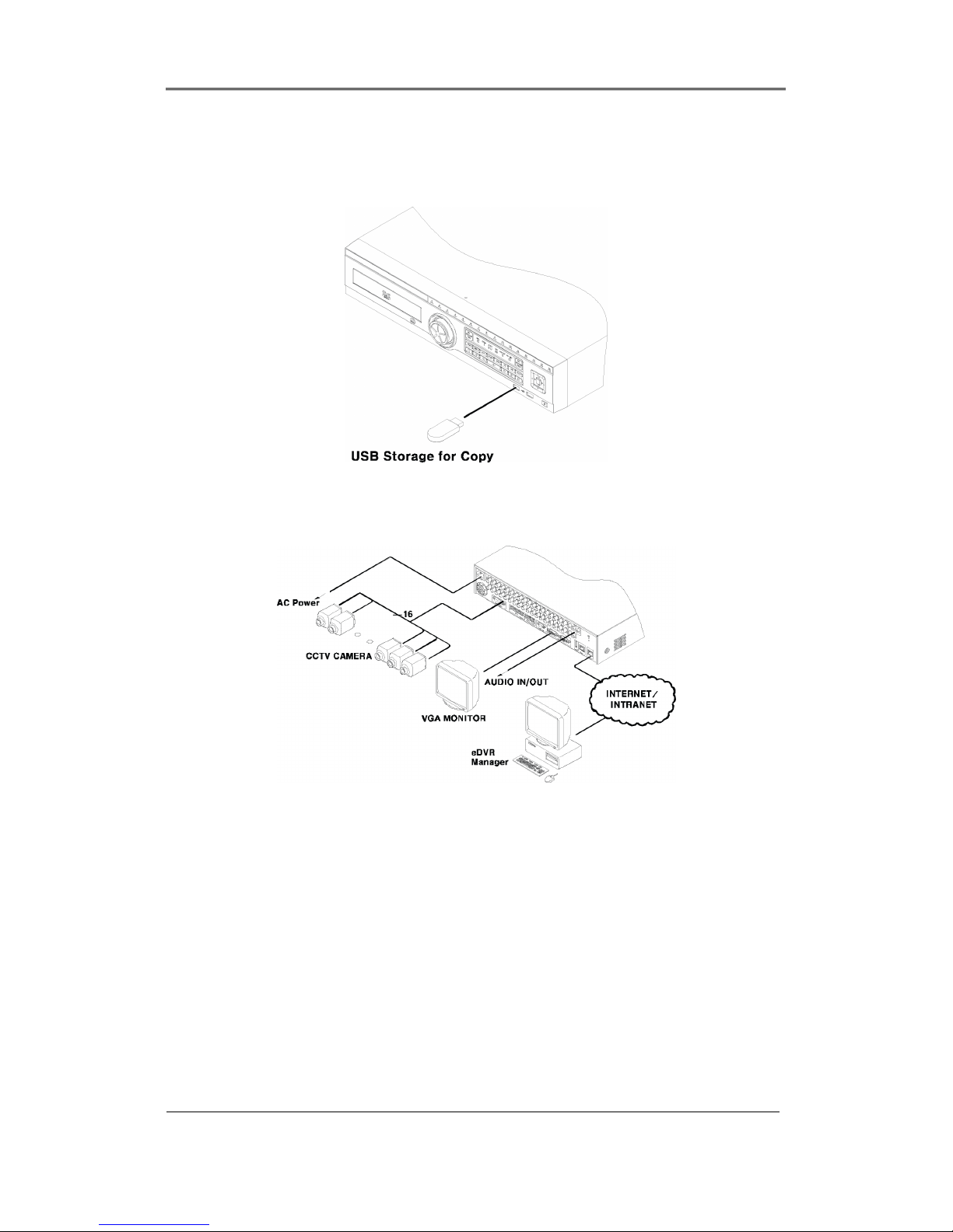
2.2.3.3 External storage & back up configuration
Use USB for back up.
2.2.3.4 Internet / Intranet configuration
Page 29
2.2.4 Basic Setting
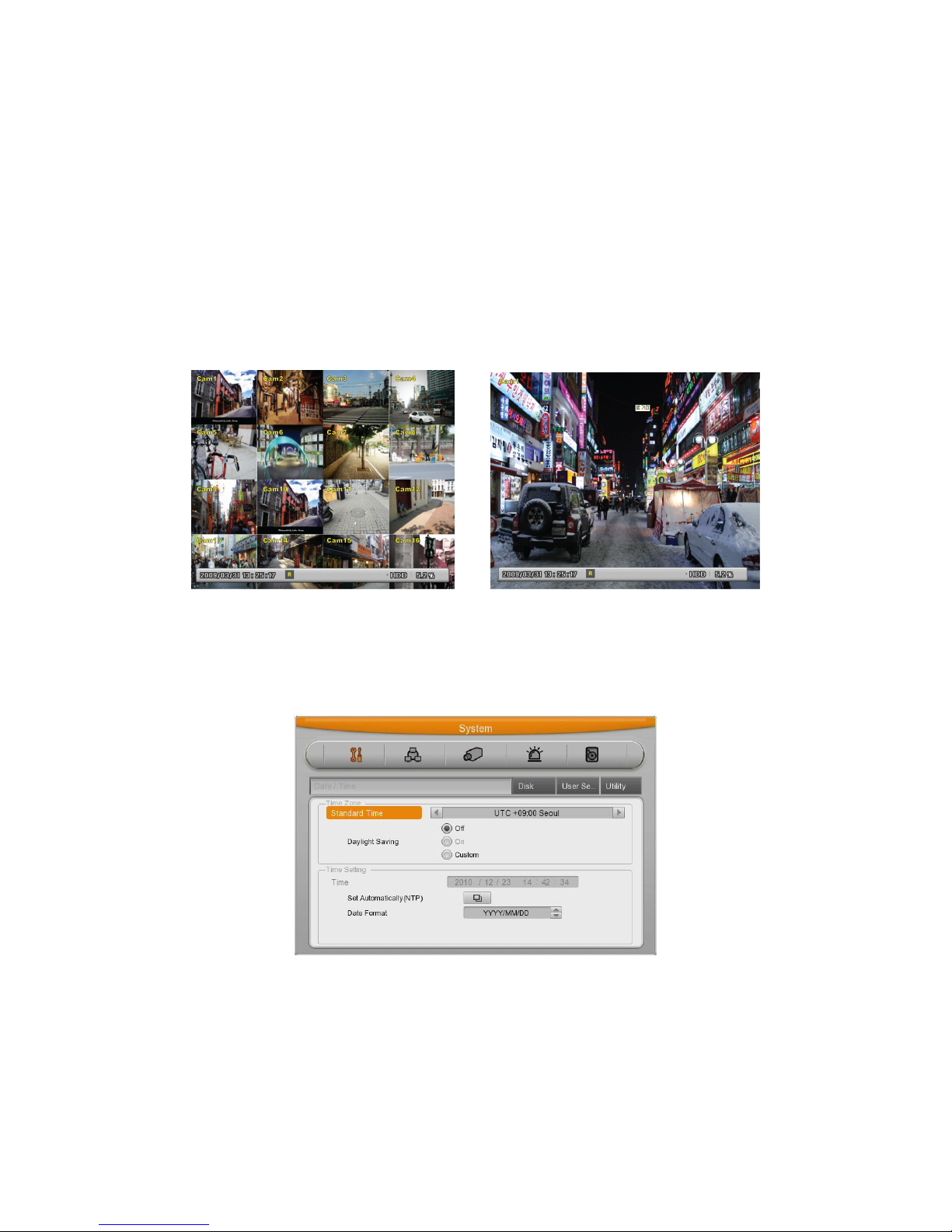
2.2.4.1 Viewing Image
When power is on, eDVR starts automatically and displayed in basic 16ch-split screen after
booting.
<Reference>
If user password is set, a prompt for entering the password will be appeared. Factory
default is reserved as not responding keypad on DVR front (It is not from factory default)
2.2.4.2 Setting Date & Time
- Press [MENU] button and select “System” when OSD menu is appeared.
- Select “Date/Time “and press [Enter] button.
Page 30

Installaction & User Manual
30
Time Zone
Use the left or right arrow key on the front or the mouse wheel to select your time zone. Each
press of the arrow keys changes the time zone. (To go to the previous menu, press the [ESC]
button on the front or right-click. This is the same for all OSD menus.)
Daylight saving
This menu is linked with “time zone” setting. For example, if the countries applied for daylight
saving in time zone setting menu then daylight saving will be turn to ON and other counties are
not applied for daylight saving then this option will be turn to OFF, and additionally the user can
configure the daylight saving option manually for the counties that were not applied, and in this
case, you can use “Custom” option to set.
The second is for selecting a month, week, and day to define the start and end times of DST.
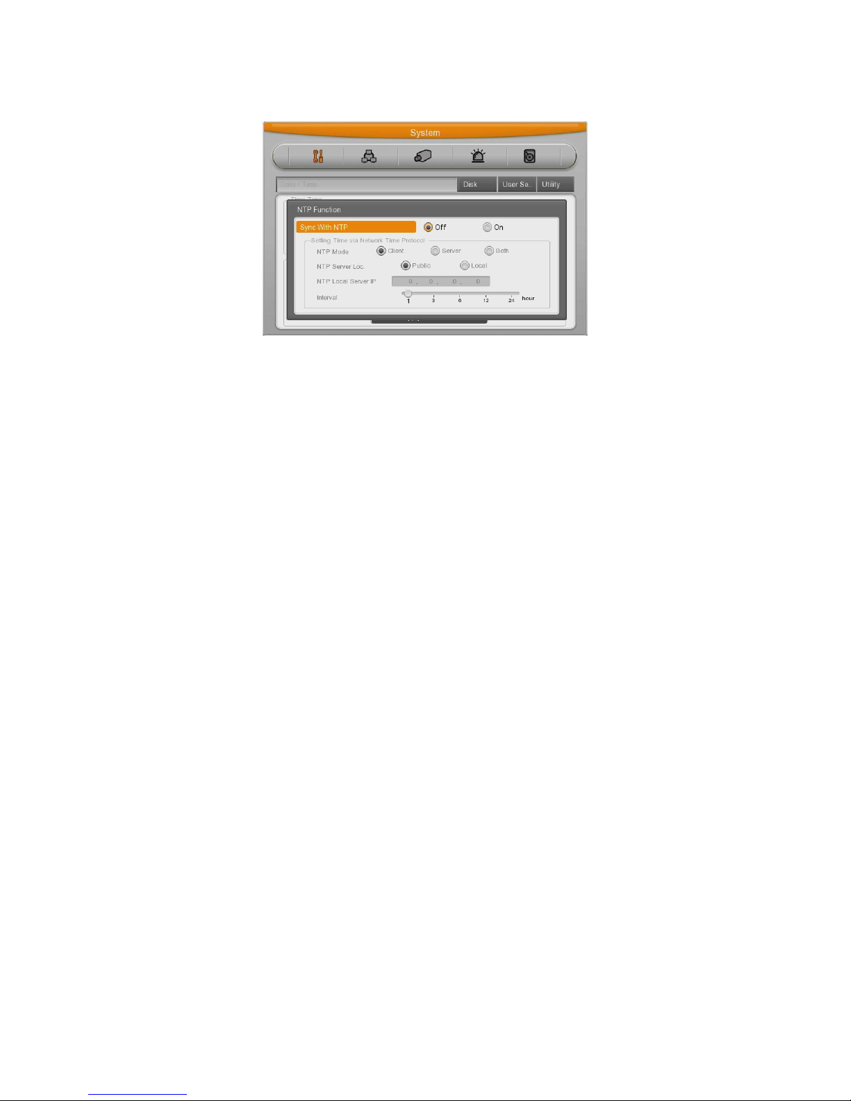
NTP
(1) Select yes or no of using NTP.
(2) Select NTP mode among Client, server, both using directional key. [◀/▶] or [▲/▼]
(3) Select Public or Both.
(4) Enter server IP address when configuring server type by Local.
(5) Configure communication interval with server.
Page 31
DATE FORMAT
(1) Select “Date Format” using [◀/▶] or [▲/▼] arrow button and press [Enter] button. Select a
value using [◀/▶] arrow button from YYYY/MM/DD, MM/DD/YYYY, DD/MM/YYYY.
(2) Press [ESC] after finishing value setting.
TIME
(1) Select “Time” using [◀/▶] or [▲/▼] arrow button and press [Enter] button.
(2) Select Date, Time using [◀/▶] arrow button and set value using [▲/▼] arrow button.
(3) Press [ESC] after finishing value setting..
APPLY
Most setting values are applied automatically, when exiting form the related menu page. But
“Date” & “Time” setting are not applied automatically because they may critically affect the file
system of the recorded HDD. To apply Date/ Time settings confirm with [Apply Date/Time]
buttons.
(1) Select “Apply Date/ Time” using [◀/▶] or [▲/▼] arrow button and press [Enter]. Then, a
warning message will be appeared as below image;
(2) Select using [◀/▶] or [▲/▼] arrow button and select “YES”, then, press [ENTER] button.
To cancel, press [ESC] button.
Page 32
Installaction & User Manual
32
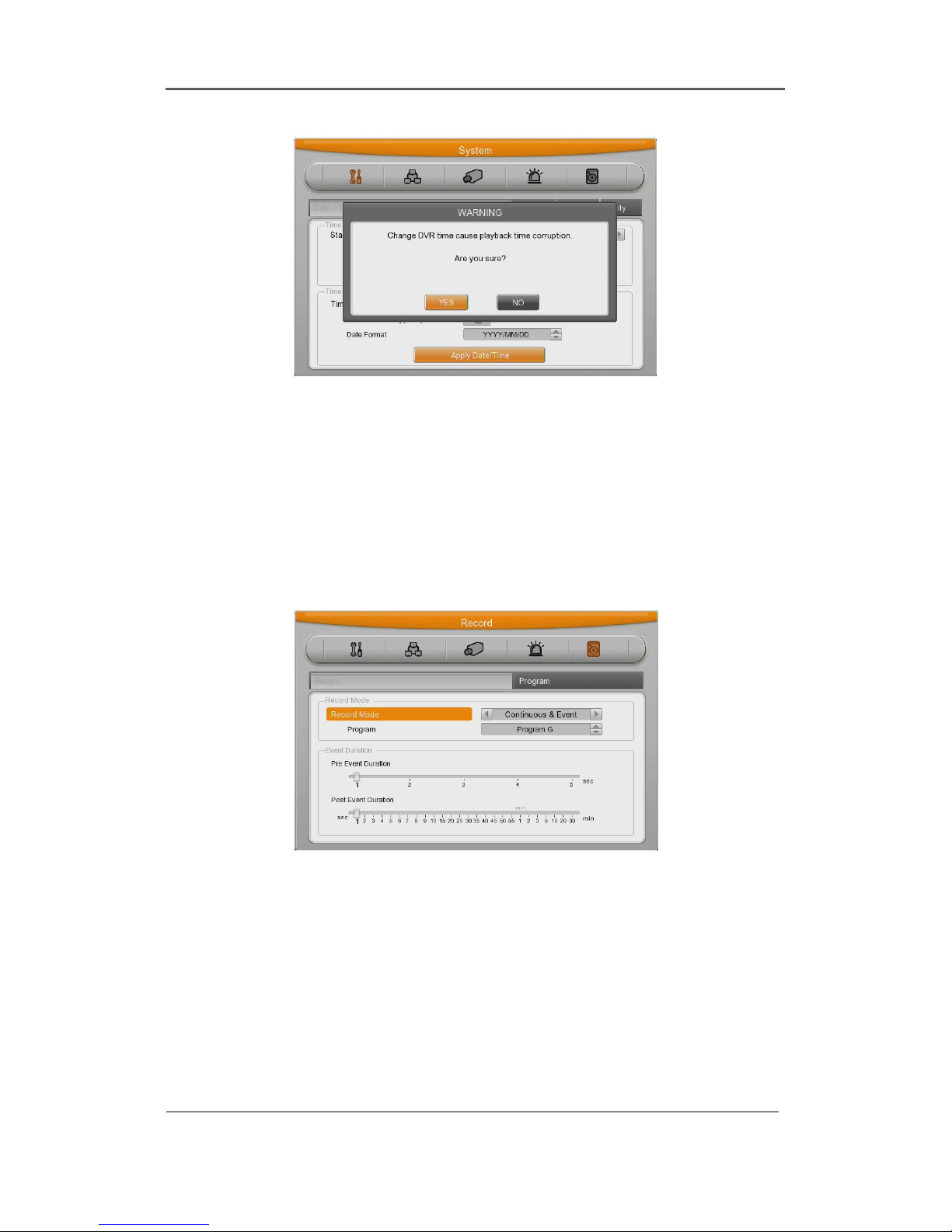
2.2.4.3 Record Setting
Select “Record” pressing menu button in front.
Manual Setting
Manual record can be configurator in “Program” of record menu and Manual / Event record is
available to Start/Stop with pressing [REC] button on front panel.
Page 33

Schedule Setting
Set the recording schedule by each channel that user want record in “Program” of record menu.
Set recording mode as “Schedule & Event” and set by date/ time.
Program Setting
Set resolution, frame rate, quality by each channel that user want record in “Program” of record
menu (See details in Record menu)
<Reference>
If recording setting is finished correctly, “REC LED” in front is flickering. In addition, it is marked
[SCHEDULE] indicating that all channels are recording.
Page 34

Installaction & User Manual
34
2.3 Connecting and configuring DIO ports
2.3.1 Wire Handlin
When connecting a wire to a terminal block, follow the instruction below. Not the different types
of wire that can be used.
- Standard wire: Pie off the wiring cover 8~10mm and solder it. Wire gage should AWG 22~26.
- Sold wire : Peel off the wiring cover 8~10mm and solder it. Wire gage should be AWG
20~26.
2.3.2 Inserting & removing wire
To insert & remove wire in Terminal Block, use a screw driver in the diagram like below.
Page 35

2.3.3 Connecting and configuring sensor
2.3.3.1 Specification
In order to run sensor input DVR normally, the following conditions are required.
Spec
Input Ch. 16EA Transistor input
Input type N.C, N.O supprt
Supported sensor Dry contact sensor
Way of connecting Connecting the trimmed wire to terminal block
Performance
Available input
pulse range
Minimum 500ms
Output current Typical DC 12mA
Connecting sensor input
Connect S1 ~ S16 with referring the following image. It shows to connect a dry contact (Please
refer “Wire Handling”.
Page 36

Installaction & User Manual
36
Setting Sensor
(1) Press [Menu] button and select “Event” when OSD menu is appeared.
(2) Move to sub menu pressing [Enter] or using [▼] button and select [Enter].
All Sensor
It is used when setting for all sensors and set off, or Normal Open (N.O.) / Normal Close
(N.C.) type.
(1) Select All and set type.
Each sensor
It is used when setting for each sensor and set selecting each sensor.
(1) Select sensor and press [Enter] button.
(2) Select sensor that user want set and set type.
(3) Press [ESC] after finishing value setting.
Page 37

2.3.3.2 Connecting relay and setting
Specification
In order to run relay output of DVR normally, the following conditions are required.
SPEC
Output Ch. 2EA relay outputs
Output type Dry contact
Connecting type Connect the trimmed wire to terminal block
Performance
DC 30V 1A
AC 125V 0.5A
Connecting relay out
Connect R1 ~ R4 with referring to the following images, it shows to connect a warning light.
Please refer the “Wire Handling”
Page 38

Installaction & User Manual
38
Relay setting
It is available to run relay selecting from sensor, motion detection, Text, Video Loss which is
normal event source and Disk error, Disk full, Fan error, authentication fail, WRS registration fail,
Mirroring fail, abnormal Recording stop which is system event source. Also, user can set
working condition by schedule. In case of using control center thru. network, relay could be run
from remotely.
2.3.3.3 Connecting serial port
Configuring serial ports for Pan/Tilt/Zoom
If DVR supports thru. COM port, it is available to connect PTZ camera and control it. For a list of
supported protocols, please refer to the list on the OSD configuration menu. The following figure
shows how to connect PTZ camera to RS485 (COM2). When using another serial port, connect
it with referring to each connection diagram below.
Please refer the “Wire Handling”.
Page 39

Serial communication port diagram
COM1 connection diagram (RS-232 – D-Sub)
COM2/COM3 diagram (RS-485)
Page 40

Installaction & User Manual
40
Available PTZ is as below
Model Manufacturer
Keyboard KBD300A, WGI SPD1800/2600
Webgate
WKC-100 keyboard
Webgate
PELCO(P), PELCO(D)
Pelco
BOSCH Auto Dome, TC8560X-4
Bosch
Sony EVI-D3x
Sony
VT VPT-4x
VT
AD Speed Dome
AD
SungJin SJ372R1
Sungjin
Samsung SCC641
Samsung Electric
Panasonic WV-CS850
Panasonic
SDZ160/330, Samsung SPD,
Keyboard SCC3000A, Samsung SRX-100B
Samsung Techwin
LG GAC-PT2
LG
Merit-Lilin Fast Dome
Merit
Elmo PTC200C
Elmo
Canon VC-C4
Canon
HTC-230S
Dongyang Unitech
RVision
RVT
Elbex
Elbex
Honeywell 755/655, HRX-2000, HTX-3000,
ScanDome2
Honeywell
VIDO
VIDO
VICON
Vicon
Page 41

Hunt
Hunt
ORX-1000
Sysmenia
Fine CRR-1600
LiveEye
Tokina
Tokina
Kodicom KRE
Kodicom
Nuvico
Nuvico
Serial Setting
You can set up at ‘serial’ menu under Device menu.
From serial setting, you can set protocol, port, baud rate, parity bit, stop bit and data bit.
After completed serial setting, select desired channel from camera menu, and setting up PTZ
Home, PTZ Idle Time, PTZ Port, and PTZ address.
Page 42

Installaction & User Manual
42
2.3.3.4 Connection to external device via Serial port
Text input device connection (ATM / POS / Access Control)
Using COM1/RS232, TEXT DATA can be recorded with synchronizing POS/ATM..
Like above picture, connect COM1/RS232 (9pin D-Sub) in Device menu and configure Serial
and Text
Serial (COM1) Setup
(1) OSD Select “Device” in OSD menu and move to sub menu.
(2) Selecting COM1 and configure “Text”in Device
(3) Setup the value of Baud Rate/Parity/Stop bit/Data bit with the device.
Text Setup
(1) Select “Deice” on OSD, and move to sub menu.
(2) Select “Text”and configure relevant text information.
Page 43

<Reference>
Since external device cannot be recognized, before installing, please, ask to the shop.
2.3.3.5 USB Device Connection
USB port is for the video copy of small data or for USB mouse. Its recommended specification is
same as below.
USB Spec. Ver 2.0
Device USB Memory Stick,
Voltage/electric
current
Max. 200mA per DC 5V / Port
<Reference>
It should be formatted by FAT32.
Page 44

Installaction & User Manual
44
In case of normal connection, if executing Copy menu, disk will be recognized same as
below and Set copy range Select Drive Execute Copy
[CD/DVD Copy]
[RE4 Copy]
Select the channel to copy.
Standard setting is selecting all channels.
Page 45

[AVI Copy]
<Reference>
A USB Flash memory which should install additional program on Windows OS, cannot be
recognized.
2.3.3.6 Video In/Out connection
Video Input/Output is Loop through and check the connectivity automatically and set end
resistance.
For instance, if connected by Video input, end resistance is configured by75Ω and if
Video in/output is same, it will be Hi-z mode. Therefore, in case that Input/Output is
connected at the same time, end resistance of device receiving output should be
configured by 75Ω.
Page 46
Installaction & User Manual
46
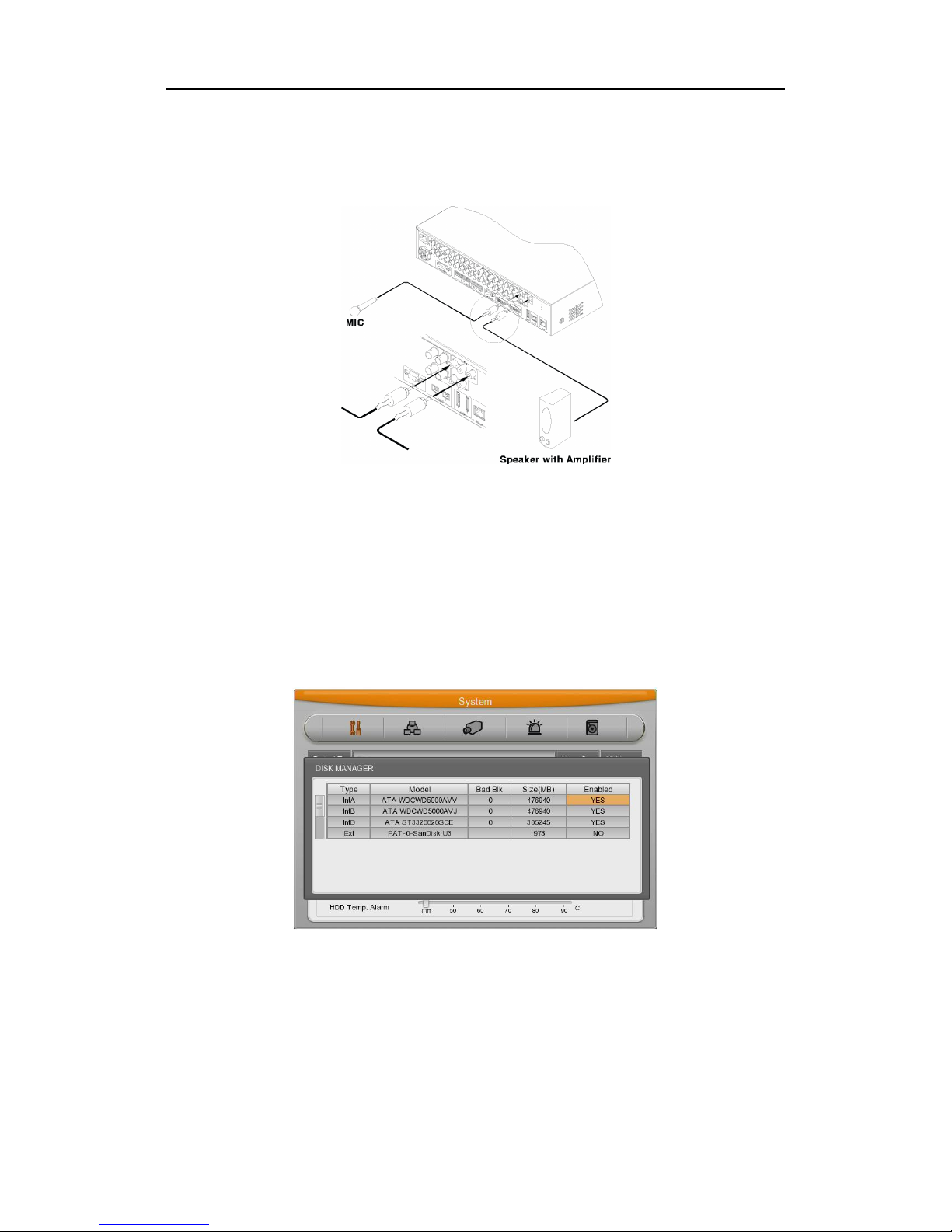
2.3.3.7 Audio In/Out connection
There are 4 RCA Audio Input and and 12 D-sub Audio input and 1 RCA output.
2.3.4 HDD
※ Please, ask to distributor or manufacturer for available HDD list.
2.3.4.1 HDD registration and format
After mounting HDD and booting system, “Disk Manager” will execute automatically.
If not, please, check the connectivity of HDD
(1) Press [Enter] button in “Disk Manager”
(2) Using [▲/▼] Key select new HDD(Displayed [No] on Enabled item) and press [Enter].
(3) If you see the message for format, select [Yes].
(4) Press [ESC] and escape from “Disk Manager.
Page 47

2.3.4.2 HDD Replacement
(1) Turn off the DVR and take off the HDD that has a problem and replace it with new
HDD.
(2) Turn On the DVR and go to “Disk Manager” menu and select the removed HDD which
has a problem, and press “Enter” Key.
(3) “Removed disk will be Confirmed” message will be pop-up and select “Yes” to delete it
from the list.
(4) Select the new HDD from the list and press “Enter” key.
(5) Select “Yes” when the system asking “do you want to format”
(6) After complete above procedure then Press “ESC” key to exit the “Disk Manager”
menu.
<Note>
1. HDD Re-using (Add Used)
You can use HDD that has been used before from DVR, in this case you do not need to do
format and delete the data.
How to use it? Please install previous HDD in the DVR, and go to “Disk Manager” menu and
select the HDD that you wish to re-use which is you just installed HDD, and press “Enter”
key then you will see the pop-up message “This disk can be added without
format/Nevertheless, do you want format this disk?” and select “NO” for re-use without
format, and select “YES” for format.
2.3.5 Remote monitor and control
Via Internet/Intranet, in remote site, user can access with PC.
2.3.5.1 Ethernet connection
Page 48

Installaction & User Manual
48
(1) Cut power
(2) Connect Ethernet cable to DVR and Hub.
(3) Input Power..
<Reference>
To protect DVR damage, after connecting Ethernet cable, input Power.
Please, check Ethernet cable connection firmly.
Input power on DVR and check their connectivity.
2.3.5.2 Network configuration
Ethernet
Set type as Ethernet and input IP, Netmask, Gateway, DNS.
The way to input is using directional key or mouse wheel.
PPPoE
Set type xDSL, and move to xDSL menu.
First, change Ethernet Port
Please, input ID and Password for PPPoE.
Page 49

WRS
After changing interval over 1 min, register WRS address and product and input Group ID.
Page 50

Installaction & User Manual
50
2.3.6 External device connection
DVR has external Storage Device Interface and 1ea of eSATA port. Using eSATA port, user can
expand Storage capacity up to 8TB.
<Note>
Since some of eSATA device can not be compatible with DVR, before the usage, please,
contact the seller and check its compatibility in advance.
2.3.6.1 eSATA Device Connection
In case of external eSATA supporting FireWire, using eSATA port on the rear part. And since
DVR does not support power to eSATA, eSATA device should be one external power is
supported.
<Note>
Basically eSATA is connected to DVR while DVR is running, works properly. However it
depends on eSATA manufacturer. Therefore, we recommend below order for making
connection.
1. Power off DVR
2. Connect external eSATA storage with power-off
3. Power on DVR
4. Power on external device after completion of DVR booting,
Page 51
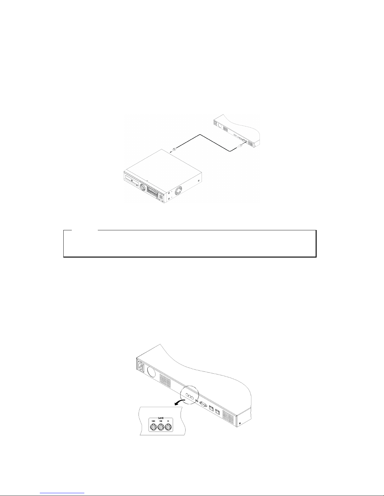
2.3.7 NVS04 connection
2.3.7.1 Connecting with DVR
(1) Connect to DVR as shown in the picture below using Gigabit Ethernet Cable.
(2) Connect DVR Port of NVS04R and Storage Port of DVR directly..
<Note>
1) The network cable connected to DVR should be Gigabit Ethernet Cable (Category-6). If not,
it is not connected to DVR.
2.3.7.2 Set ID Configuration
Set ID using Rotary Switch located on the back. This ID is used as IP Address of NVS04R and
the form of IP address is 10.10.20.XXX. when the user connect more than 2 units of NVS04R,
each ID should be set differently.
Page 52

Installaction & User Manual
52
Set the ID using driver. The value for the first digit of switch should match with values of 100x on
the rare panel while the second digit of switch should match with value of 10x and the third digit
of switch should match with 1x on the rare panel
2.3.7.3 Power connection and operation
(1) Connect power as below.
(2) As soon as power is connected, the device starts booting.
<Note>
1) It takes around 1 minute to connect NVS04R and DVR after connecting power.
Four LEDs at the front starts blinking and they are fully on when connection is completed. The
HDD list is available to check at Disk Manager
2) Refer the manual of “NVS04R installation and user guide” for detailed explanation..
Page 53

User Manual
3. Menu Use
3.1 Menu Structure
The menu structure will be shown like below image, and each menu setting method descriped
from chapter 4 to chapter 6.
3.2 Function Menu
To run Function menu, please, click the right button of mouse in live monitoring or playback
status or push “Func” button on the front panel.
The Function menu can be controlled by mouse.
Each function can be executed by clicking right button of mouse and click desired icon.
The Function menu also can be controlled by front part of DVR’s buttons.
Please refer to below picture for the Function menu structure.
Function of Live
Page 54

Installaction & User Manual
54
Function of Playback
3.3 Factory Reset
In order to reset value to factory value, go to System Setting->System->Setting, and once press
Factory Reset then the warning message will be appear, click “Yes” to reset the DVR value to
factory.
Default Value from Factory
System
Date /
Time
Time Zone UTC 00:00 Dublin
Daylight Saving Off
NTP Function Sync With
NTP
Off
NTP Mode Client
NTP Server
Loc.
Public
NTP Local
Server IP
0.0.0.0
Interval 1(hour)
Date Format MM/DD/YYYY
Time Current Time
Disk
Over Write On
Disk Full Alarm
Warning
55
Block Playback 0
Delete Data Off
Disk Mirroring Off
HDD Temp Alarm Off
Page 55

User
Setup
Right
O
Utility
DVR Alias DVR0
Language English
DVR Keyboard ID 1
Remote Controller
ID
All
Network
Network
Type Ethernet
DHCP Off
IP addr Current IP
Net Mask Current Net Mask
Gateway Current Gateway
DNS Server 4.2.2.1
Port 80
Band Width
Limit(Mbps)
0.0
xDSL
User ID Guest
Password *****
Status xDSL not connected
DDNS
Interval Off
URL www.webgateinc.com
Group Newbie
Status Not Registered
Radius
Status Disable
IP Address 0.0.0.0
Port 1812
Device
Camera Camera Number Ch1
Status On
Name Cam 1
Type NTSC
AGC Enable
Bright 0
Contrast 0
Mosaic Off
Page 56

Installaction & User Manual
56
PTZ PTZ Home Off
PTZ Idle
Time
5
PTZ Port None
PTZ Address 0
Monitor
Monitor Minitor1
Alarm Pop-up(Sec) Off
Scan Mode Over Scan
VGA Mode 800x600@56Hz
Monitor Switching On
Audio
Audio Channel 1
Audio Recording Off
Sync Video Channel Ch1
Audio Gain 0
Audio Mix Mix On
Text
Recording Off
Sync Test With Ch1
Device Manual
Seek Header Off
Header 1 Header1
Header 2 Header2
Delimiter 0D0A
Timeout(ms) 1000
Lines 20
Serial
Serial Port Com1
Device None
Interface RS232
Baud Rate 9600
Parity Bit None
Stop Bit 1
Data Bit 8
Event
Event
Event Check Always
Event Action Relay1
Action Duration 10 Sec
Motion MD All
Page 57

Sensivity 5
Area Set All
Sensor Sensor All, N.O.
Preset
Channel Number Ch1
Preset Sensor1, Preset1
Record
Record
Record Mode Manual & Event
Program Program A
Pre Event Duration 1
Post Event Duration 1
Program
Normal Resolution All D1
Frame Rate MH1600H : All 30, MH1600M, 3200M :
All 15
Quality All Q5
Event Resolution All D1
Frame Rate MH1600H : All 30, MH1600M, 3200M :
All 15
Quality All Q5
Factory Default value (NTSC)
MH1600H
Rec mode Normal Event
List Res Fps Q Res Fps Q
Program
A D1 30 Q5 D1 30 Q5
B D1 15 Q5 D1 15 Q5
C D1 7 Q5 D1 7 Q5
D Half 30 Q5 Half 30 Q5
E Half 15 Q5 Half 15 Q5
F Half 7 Q5 Half 7 Q5
G CIF 30 Q5 CIF 30 Q5
H CIF 15 Q5 CIF 15 Q5
I CIF 7 Q5 CIF 7 Q5
MH1600M
Rec mode Normal Event
Page 58

Installaction & User Manual
58
List Res Fps Q Res Fps Q
Program
A D1 15 Q5 D1 15 Q5
B D1 7 Q5 D1 7 Q5
C D1 4 Q5 D1 4 Q5
D Half 30 Q5 Half 30 Q5
E Half 15 Q5 Half 15 Q5
F Half 7 Q5 Half 7 Q5
G CIF 30 Q5 CIF 30 Q5
H CIF 15 Q5 CIF 15 Q5
I CIF 7 Q5 CIF 7 Q5
MH3200M
Rec mode Normal Event
List Res Fps Q Res Fps Q
Program
A D1 15 Q5 D1 15 Q5
B D1 7 Q5 D1 7 Q5
C D1 4 Q5 D1 4 Q5
D Half 30 Q5 Half 30 Q5
E Half 15 Q5 Half 15 Q5
F Half 7 Q5 Half 7 Q5
G CIF 30 Q5 CIF 30 Q5
H CIF 15 Q5 CIF 15 Q5
I CIF 7 Q5 CIF 7 Q5
Page 59

4. Monitoring
All analog video image channels connected to DVR is displayed to screen by Power connection.
It is to utilize all monitoring mode of DVR.
4.1 Basic Screen
After Power connection, the DVR operates on
automately.
It boots with LED on.
4.2 Single Full Screen Mode
After press the channel number wanted or click mouse
button.
Press [MULTI] button to return to divisional screen
4.3 Multi Screen Mode
Press [MULTI] for multi-channel display or click
“Display” icon from Function menu.
Press [MULTI] button every time, screen mode is
changed to 1~4, 5~8, 9~12, 13~16, 4C, 1~9, 8~16, 1~10, 16 channel division.
4.4 Screen Description
The status bar from monitoring screen, it shows DVR’s current status that included Date/Time,
Record, Motion/Sensor Detection, Manual Record, Text input and HDD’s record capacity.
Page 60

Installaction & User Manual
60
4.5 Auto Switch Mode (Sequence)
Defined channels or multi screens can be displayed in sequence with configurated time interval.
Maximum 16 channels or multi screens can be defined.
.
4.5.1 System Standard Mode
By [SEQ] button, it can monitor auto switching of defined channels.
Press [MENU] for the setting switching term or using mouse click menu icon from function
menu.
Move to “Device” “Monitor” from OSD menu.
Select “Monitor” under ‘Device” with [Enter] button or mouse click. Set value from 1 sec. to 60
sec. At OFF set, auto switch mode does not operate
Auto Switch mode can be set in every division mode by the press [SEQ] button.
Press [SEQ] button once more to leave from Auto Switch mode.
Page 61

4.5.2 User Sequence Mode
[Press [AUTO] button or click [Sequence] icon from Function menu with mouse.
Auto Switch model can be set from “Monitor” main menu.
4.6 Event Screen
When the event is occurred, the green color [M] and red color [S] will be display from status
bar. In case of [M] displayed, the camera name will be turned to green color, and it will turn to
yellow when Motion Detection event finish.
In case of [S] displayed, the camera name will be turned to red color, and it will turn to yellow
when Sensor event finish
It can be set to Pop-up automatically relevant screen when alarming.
Set pop-up period can be set into “Alarm Pop-up (sec)” inferior to “Monitor” menu.
At the simultaneous alarming in several channels, it displays the division as many channel as
alarmed. For example, when 3 channels alarm, 4 divisions is displayed on screen. And press
any button to return original channel.
Page 62

Installaction & User Manual
62
1. If Alarm Pop-up Hold (sec) set to Off, Alarm Pop-up will not operate.
2. If Alarm Pop-up Hold (sec) set to keep, it does not return to previous screen before press any
button.
4.7 Zoom Screen Mode
- From single full screen mode, press [FUNC] and D-Zoom button then select + button to
activate zooming the image.
- Default zoom screen locates to main center when press [ZOOM] button. Zoom image can
shift left-right in 18 steps and top-bottom in 12 steps.
- Use directional key(up/down/left/right) button to screen move.
- Press [-] one more with [Enter] or mouse click to return to original screen.
4.8 Pause Live Screen
- Live screen can pause like Playback.
- Press [PAUSE] to pause live screen and press [PAUSE] to return live screen.
Page 63

4.9 PTZ Control
Connect PTZ controller to DVR and set relevant protocol from “Serial” menu, then PTZ can
operate while monitoring live images.
Then PTZ works automatically with following icon.
PAN/TILT can be used with directional button on front panel, and PAN/TILT/ZOOM can be
used with mouse.
Press PTZ button from DVR’s front panel, or click PTZ icon from Function menu to use OSD
Menu, Focus, Preset, Aux.
Page 64

Installaction & User Manual
64
Below lists are protocols available in DVR
Model Manufacturer
BOSCH AutoDome, TC8560X-4
Bosch
PELCO(P), PELCO(D)
Pelco
Sony EVI-D3x
Sony
VT VPT-4x
VT
AD Speed Dome
AD
SungJin SJ372R1
SungJin
Samsung SCC641
Samsung Electric
Panasonic WV-CS850
Panasonic
SDZ160/330, Samsung SPD,
Keyboard SCC3000A, Samsung SRX-100B
Samsung Techwin
LG GAC-PT2
LG
Keyboard KBD300A, WGI SPD1800/2600
Honeywell
WKC-100
Honeywell
Merit-Lilin Fast Dome
Merit
Elmo PTC200C
Elmo
Canon VC-C4
Canon
HTC-230S
DongYang Unitech
RVision
RVision
Elbex
Elbex
Honeywell 755/655, HRX-2000, HTX-3000,
ScanDome2
Honeywell
VIDO
VIDO
VICON
Vicon
Hunt
Hunt
ORX-1000
Sysmenia
Fine CRR-1600
LiveEye
Tokina
Tokina
Kodicom KRE
Kodicom
Nuvico
Nuvico
Page 65

4.9.1 Pan/Tilt/Zoom
This menu is used to control Pan / Tilt / Zoom function.
Select relevant channel to control PTZ which is connected with PTZ.
4.9.2 Focus
Press [PTZ] button in PTZ screen to activate Focus menu.
Control focus with [Near] or [Far] buttons .
4.9.3 Load Preset
Press [PTZ] button in PTZ screen to activate Load Preset menu.
Select Preset number wanted and press [Load] button
4.9.4 Save Preset
Press [PTZ] button in PTZ screen to activate Save Preset menu.
Select Preset number when you want to save and press [Save] button
4.9.5 Auxiliary On
Press [PTZ] button in PTZ screen to activate Aux On menu..
- Using up / down button or mouse wheel to select the Aux Number.
- Select On and press Enter button or click from mouse.
(Aux function is available to max 16 functions.)
4.9.6 Auxiliary Off
Press [PTZ] button in PTZ screen to activate Aux Off menu..
- Using up / down button or mouse wheel to select the Aux Number.
- Select Off and press Enter button or click from mouse.
4.9.7 Menu
It is to go into connected PTZ’s menu, using up/down/left/right and enter key from front panel for
setting the menu, and press ESC button for exit the menu.
Page 66

Installaction & User Manual
66
5.Playback
5.1 Playback Mode
5.1.1 Playback on Standard monitor (16 / 9 division)
- Please, push play button in monitoring mode or mouse click play button in Function menu.
- If pushing Play button or FWD button, video playbacks in forward direction at 1× speed.
- If pushing REW button, video playbacks in reverse direction at 1× speed.
- If pushing Playback button in multi-division monitor mode,
.
5.1.2 Playback function
◀▶
: Playback 1× speed. If using mouse, click Play button in Function
menu.
Multi-channel video will play back if pushing [PLAY] button in monitor
mode. And it playbacks from the latest played back. If pressing this
button one more during playback, playback direction is reversed.
ll : Pause playback temporary. With mouse, click Pause button in
Function menu.
■ : Stop playback. With mouse, click Stop button in Function menu.
▶▶ : Playback speed will be changed. (x1, x2, x4, x8, x16, x32, x64, x1/2,
x1, x2, x4 – in order), If pushing [FWD] button in live view, it plays back
video 1 minute ago. Playback speed can be changed by pushing
[FWD] button or clicking [FWD] button in Function menu.
◀◀ : Reverse playback speed will be changed. (x1, x2, x4, x8, x16, x32,
x64, x1/2, x1, x2, x4 in order)
If pushing [REW] button in live view, it plays back video 1 minute ago.
Playback speed can be changed by pushing [REW] button or clicking
[REW] button in Function menu
l▶ : If pushing [FWD] button on Pause mode, playback by each frame to
the forward. Push [PLAY] to return normal playback.
◀l : If pushing [REW] button on Pause mode, playback by each frame to
the reverse. Push [PLAY] to return normal playback.
Jog/Shuttle : changeable to various playback speeds (x1, x2, x4, x8, x16, x32, x64,
x1/2) with either playback direction in playback status.
Page 67

5.2 SEARCH MODE
This menu is to playback specific time data from the time frame and searching log at Playback
mode.
There are Time, Calendar, Event, Thumbnail mode.
Please, push Search button on the front panel or click in Function menu..
5.2.1 Time Search
Select date and time to search and playback video will be moved to the selected point.
Start-REC Time : The date and time of start-recording
End-REC Time : The latest date and time of the recording
Search Time : Select the range of date and time for Search
Search : Execution button
5.2.2 Schedule Search
[MH1600H, MH1600M]
Page 68

Installaction & User Manual
68
[MH3200M]
Display recording status of channel 1~32
Year : Select Year to search. With mouse wheel, user can change it.
Month : Select Month to search. With mouse wheel, user can change it.
Date : Select Date to search. With mouse, select the date and decide the
time by wheel.
Time : Select the time and push Enter button to play back.
5.2.3 Event Search
User can search by all channels, some of channels, all events, motion detection, sensor in
certain range. For change of date and time, with front panel, please use top and down button. In
case of using mouse, scroll the mouse wheel after selecting area. Searched result will be
displayed on additional event window. Select and push enter or scroll the mouse wheel to move
to the wanted date and time area.
Start-REC Time : Starting date and time of the recording.
End-REC Time : The latest date and time of the recording
Search Start
Time
: Input start date and time for search with direction button and push
Enter and change the value by Up and Down button. With mouse, click
and scroll the wheel.
Search end Time : Input end date and time for search with direction button and push
Page 69

Enter and change the value by Up and Down button. With mouse, click
and scroll the wheel.
Event Channel : Select the channel for search
MH1600H, MH1600M: from Ch1 to Ch16
MH3200M from Ch1 to Ch32
Event Type : Select the event type for search
There are all events, motion detection, sensor, video loss, text type
Smart search : It’s a function that search the object by motion detecting.
1. Choose channel that you want to search.
2. Choose event type on MD(Motion Detection)
3. Set the grid for motion and go to search.
After event search, following result is displayed
Select one of them to playback the relevant recorded data.
5.2.4 Thumbnail Search
Search certain channel by thumbnail type. If select the searched thumbnail, selected date and
time video will be played back..
Channel : Select the channel and change the value by direction key or mouse
wheel.
Start Time : Input the date and time for starting search and change the value
Page 70

Installaction & User Manual
70
using up-down direction key or mouse wheel.
Interval : Set Interval value by Up-down button or mouse wheel.
View video : If pushing search button, 16 cycles will be shown based on start time.
Press [Func] to return to the search or use mouse wheel.
Select video : Play back from the selected video of thumbnail search result.
With pressing Enter or clicking mouse, use can play back.
After Thumbnail search, following result is displayed
Select one of them to playback the relevant recorded data
Page 71

5.3 Copy
This is for copying recorded video. There are CD/DVD and RE4 and AVI type.
Copy function is supported to be used by user who has the authorization. For authority
configuration, please, refer to 6.2.3 User setup
To use copy function, press [COPY] or Click Copy button in Function menu.
5.3.1 CD/DVD
This is copy function by using CD or DVD. CD or DVD will be automatically searched..
Type : Select CD/DVD using up-down direction key or mouse wheel. Press
Enter and scroll wheel to change the value.
Channel : User can select some or all channel among 16channels. Select the
channel location and press Enter or use mouse wheel.
From : Select start date and time to copy using up-down key or mouse
wheel.
To : Select end date and time to copy using up-down key or mouse wheel.
Select Disk : Select the media to copy using Enter button on Select Disk.
Start : Start Copy. Press Start button with Enter or click the left button of the
mouse.
FAT32 format : Format USB memory or HDD by FAT32 type.
Do not use when copying into CD/DVD. First execute format and
select FAT32 button and press Enter or click left mouse button.
Estimated File Size Display file size of recorded data which is selected.
Page 72

Installaction & User Manual
72
Please, refer to the recommended media list below.
DVD-R manufacturer CD-R Manufacturer
Mitsubishi(×16 recommended) Mitsubishi(×52 recommended)
TDK(×16 recommended) TDK(×52 recommended)
Imation(×16 recommended) Imation(×52 recommended)
Sony(×16 recommended) Sony(×48 recommended)
5.3.2 RE4
User can back up by HDD, USB memory and play back suing mini-player or Control Center.
Select channel position and press Enter or use mouse wheel to open the channel list like below..
[MH1600H, MH1600M]
Page 73

[MH3200M]
Type : Select RE4 using up-down button or mouse wheel.
Channel : To pop up the channel selection window, press Enter or use mouse
wheel.
Select Channel : use can select some or all channels and after selecting channel,
press Enter or click mouse left button.
Start time : Set start date or time to copy. After selecting part for change and set
the value using up-down key or mouse wheel.
End time : Set End date or time to copy. After selecting part for change and set
the value using up-down key or mouse wheel.
Select disk : Select media to copy. Press Enter on Disk list or click mouse.
Start : Start copy. Press Enter or click mouse.
FAT32 format : If USB memory or HDD are not formatted, format by FAT32 first and
copy. To execute, press Enter or click mouse.
Caution : not perfectly finished backup file will not be played back in PC.
Page 74

Installaction & User Manual
74
5.3.3 AVI
Use USB memory or HDD to copy certain part.
Type : Select AVI using up-down key or mouse wheel.
Channel : Select the channel to copy by up-down key or mouse wheel.
From : Set start date and time to copy. Time and Year by left/right button and
date/time by up/down button. With mouse, click left button first and use
wheel.
Duration : Set copy length. Copy as selected time length from the start using
up/down key or mouse wheel.
Select disk : Select media to copy. Press Enter and select media or click mouse.
Start : Start copy. Press Enter or click mouse.
FAT32 Format
: Format USB Memory or HDD not formatted.
Caution : If copied file is not played back, please, install integrated codec first.
Page 75

6. Configuration
6.1 Recording Structure
There are 3 modes in DVR recording. Configuration relation structure is like below.
Please, refer to the below each item for detailed recording configuration.
6.2 System Setup
Time and Disk and authority can be configured.
6.2.1 Date/Time
Time set should be configured prior to the recording.
Page 76

Installaction & User Manual
76
Time configuration is very important to protect the recording data. Time change on recording is
not recommended. Time zone configuration value of factory default is “UTC 00:00 Dublin”
6.2.1.1 Time Setup
Caution: under recording, if user changes Time, it will affect time change on previously
recorded video data in accordance with. Therefore, we recommend backup before time
change.
- Press Main Menu of Function or [MENU] button on the front panel.
- Move to “Date/Time” menu.
- After selecting “Date/Time” in Quick setup and press [Enter] or click.
- Menu of time configuration 6.2 will be opened
- To move to the sub menu, use directional key or mouse.
Time zone
Use left/right direction key or mouse wheel. To return to previous menu, press [ESC] or click
right mouse button. (It is same as OSD menu)
Daylight saving
This menu is synchronized with time zone configuration menu. It means when daylight saving
area is set, this function works. Daylight saving applicable area is all the same with Time zone
of Microsoft Windows.
Date format
With using left/right direction key or mouse wheel, configure date among “MM/DD/YYYY”,
“YYYY/MM/DD”, “DD/MM/YYYY”.
Page 77

Time
With left/right direction key, use can move to year, month, day, hour in order and each
configuration will be controlled by up/down key or mouse wheel.
Apply
User must push “Apply Date/Time” button. And you will see the below message box.
<Caution>
Except date/time configuration, other configuration records automatically, but
“date/time” configuration influences critical effect to HDD recording file system,
It doesn’t record automatically. To apply the changed value, user must press
[apply] button.
Page 78

Installaction & User Manual
78
6.2.1.2 NTP Setup
NTP(Network Time Protocol) make time of connected devices synchronized. There are NTP
server and client which get time signal from the server.
Sync NTP
Set NTP function on/off.
NTP Mode
Configure NTP mode of DVR – Client / Server / All
NTP Server Loc.
When NTP mode is client, it is on Enable. Configure yes or no whether NTP server is in Local
Network or Public.
NTP Local server IP
In NTP local server Enable, configure server ip. Input IP address of NTP server or DVR set by
NTP server in local network.
Interval
Configure interval of time sync.
Caution: If use NTP client mode, user must set NTP on.
Page 79

6.2.2 Disk
It explains how to add or remove or format internal or external HDD.
Over Write
If there is no space in HDD, old data will be deleted automatically.
Disk Full Alarm Warning
It gives notice if the recorded data is full up to configurated limitation of all HDD disks which is
connected to DVR.
Block Playback
This function makes recording data seen during the limited area.
For instance, if setting block playback by 2 day(Pic 2) among 10 days, just allowed 2 days data
can be played back.
Delete Data
This option is to record only the date you selected.
For example, if you select 3 days then DVR will record up to 3 days, and keep overwriting
3 days period of data
Disk Full Alarm Warning
If mounted Disk is full, alarm warning to user.
Page 80
Installaction & User Manual
80
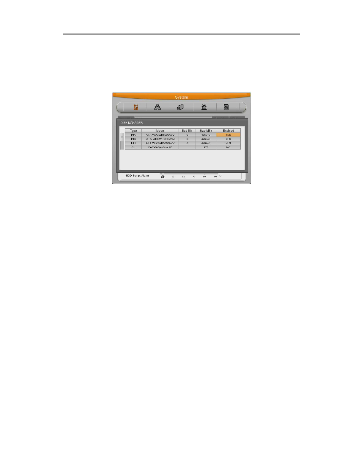
6.2.2.1 Disk Manager
This is menu for the management of internal or external HDD.
Manage status, bad block, size, Yes or No etc.
Type : display location or type of disk.
Int A (Internal A HDD), Int B (Internal B HDD), Ext (External HDD)
Model : HDD model name.
Bad Blk : display bad block. In HDD. If no problem, “0” will be displayed. Others
are
Not shown anything at all.
Size : Display HDD size by MB unit
Enabled : Make HDD enable mode or disable mode.
Yes: enable / No: Disable
In case HDD YES
- Enabled : Press [Enter] in No mode or scroll mouse wheel. Notice window pops up and show
user the message like below.
- Caution : This Disk is not available without format. Will you format Disk?
- If selecting No, keep previous data and HDD will be Enable to use.
- If selecting yes, delete previous data and HDD will be Enable to use.
In case HDD No
- Enabled : In Yes mode, press [Enter] or scroll mouse wheel and notice window pops up and
show user the message like below.
-Caution, will you remove Disk?
- If Yes, user will find the message “Disk is removed” on the bottom and Enable status
will be No.
Page 81

- HDD is not used.
- If No, keep previous HDD without change.
6.2.2.2 Disk Status
Temperature and status of HDD will be shown.
6.2.2.3 Disk Mirroring
This DVR has DVR Mirroring function in itself and NVS Mirroring on NVS(Network Video
Storage) via Gigabit Network
[1
Without additional user control, if connecting DVR and NVS via Gigabit Network Cable,
Mirroring function will be activated and user can operate it easily and simply.
But, when using Mirroring function, DVR system performance will be down and recording
configuration will be automatically adjusted.
Recorded Video data via Mirroring function can playback in another DVR. But if user wants to
use the HDD for recording, it should be formatted again.
□ File system supporting Max. 32TB
□ Support max 8ea of NVS via Cascade Network Port.
□ Support Local(DVR) 2 bay / NVS 4 bay SATA Hot Swap Bay
□ Support Local(DVR) Recording 8TB (4TB with Mirroring)
□ NVS recording 32TB (Mirroring 16TB) will be supported soon.
[1]
Category 6
Page 82

Installaction & User Manual
82
DVR Mirroring working method
Mirroring
Mirroring
Mirroring
Mirroring
(1) Basically HDDs will be set like the above.
(2) Recording data of HDD-3 is mirroring with HDD-1 and recording data of HDD-4 is
mirroring to HDD-2.
(3) If there are 4ea of HDDs are mounted on DVR and starts recording, HDD-4 will start
recording.
(4) If HDD-4 is full, automatically HDD-3 will start recording.
(5) In case that Disk Auto Deletion is configured, when HDd-3 is full, automatically system
return to HDD-4 and it will overwrite from the oldest data for recording.
(6) To check Mirroring recording data, it will be possible on the additional DVR. Removed
Mirroring HDD should be used only for keeping or Playback. And if user wants to reuse
Mirroring HDD for recording, it should be formatted.
Page 83

Mirroring configuration
- Off : All mounted HDD will be recorded in order without Mirroring.
- DVR : Mirroring recording only with internally mounted HDD ( not HDD in NVS04R)
- NVS : Mirroring recording only with HDD in NVS04R which is connected to DVR. (Not HDD
in DVR)
- All : Mirroring recording with all HDDs in DVR and NVS04R.
(1) Using directional key in Disk Mirroring configuration, please, select DVR for use and press
Enter.
But, before Mirroring configuration, all HDDs should be Removed – (Remove(NO).
(2) After configuration with Enter, if Pop-up message window is shown, select YES.
(3) After moving to Disk Manager, all mounted HDDs are supposed to be formatted and IntA,B
is configured as [M] (Mirroring) and IntC,D maintains [NO] status.
(4) After selecting Int C,D and then Add(YES), select YES on Pop-up window ad press Enter.
(5) Configured HDD is shifted from [NO] to [YES] and DVR can use the HDD for recording.
(6) After all configurations for Mirroring, if it works properly, HDD for recording and HDD for
Mirroring LED of the front panel will be blink. If not recording, front LED will off
Page 84

Installaction & User Manual
84
<Note>
1. For Mirroring function, HDDs capacity and model for Recording and Mirroring should
be same. If not, it won’t work.
But, in case that HDD capacity is same but just different model, sometimes, it can not
work properly.
Ex) Example for normal Mirroring and abnormal Mirroring
1) Normal Mirroring case
Type Model Bad Blk Size(MB) Enabled
IntA ATA WDCWD5000AV
0 476940 No
IntB ATA ST3250820AS 0 238475 No
IntC
TA WDCWD5000AV
0 476940 No
IntD ATA ST3250820AS 0 238475 No
2) Abnormal Mirroring case or not recommended.(different model and size)
Type Model Bad Blk Size(MB) Enabled
IntA ATA WDCWD5000AV
0 476940 No
IntB ATA ST3250820AS 0 238475 No
IntC ATA ST3250820AS 0 476940 No
IntD ATA ST3250820AS 0 479640 No
2. For Mirroring configuration, HDD status of all HDDs in existing DVR and NVS04R should
be [NO].
If, one of HDDs is not [NO] status, since Mirroring configuration will be failed, please,
remove HDD and make all HDDs at [NO] status.
But, except HDDs formatted by FAT32 from CD/DVD or external storage (eSATA,
Page 85

IEEE1394, USB).
3. For Mirroring configuration in NVS04R or DVR, other HDDs should not be added
except its Mirroring configuration.
Ex) For NVS04R Mirroring configuration, all HDDs in DVR should be [NO] status.
Recording Configuration.
When using Mirroring function, according to configuration option, DVR system performance will
be down and due to this reason, recording configuration
will be adjusted automatically like below table chart.
1) Maximum recording performance per model with NVS Mirroring configuration.
[ MH1600H Model ]
NVS Mirroring Recording Setting
Resolution IPS Quality
D1 15 ~ 1 Q5 ~ Q1
Half 30 ~ 1 Q5 ~ Q1
CIF 30 ~ 1 Q5 ~ Q1
[ MH3200M / MH1600M Model ]
NVS Mirroring Recording Setting
Resolution IPS Quality
D1 7 ~ 1 Q5 ~ Q1
Half 15 ~ 1 Q5 ~ Q1
CIF 30 ~ 1 Q5 ~ Q1
2) Maximum recording performance per model with DVR and NVR04R Mirroring function
[ MH1600H Model ]
DVR/All Mirroring Recording Setting
Resolution IPS Quality
D1 7~1 Q5 ~ Q1
Half 15 ~ 1 Q5 ~ Q1
CIF 30 ~ 1 Q5 ~ Q1
Page 86

Installaction & User Manual
86
[ MH3200M / MH1600M Model ]
DVR/All Mirroring Recording Setting
Resolution IPS Quality
D1 4 ~ 1 Q5 ~ Q1
Half 7 ~ 1 Q5 ~ Q1
CIF 15 ~ 1 Q5 ~ Q1
6.2.2.4 Mirroring HDD replacement.
If Mirroring HDD free space becomes 0%, on DVR console screen, alarm pop-up message will
be shown for Mirroring HDD replacement. This time, user can check Mirroring HDD free space
in Disk Replace menu and user can replace it.
Loc : Mirroring HDD name
Free : HDD free space
From : Date and time of Start recording.
To : Date and time of End recording
State : If free space is enough, it is displayed by Mirroring and if 0%, displayed by Replace. With
these information, user can notice the HDD replacement timing..
<Note>
1. For Mirroring HDD replacement, user must do it in HDD Change menu..
2. This time, HDD for replacement should be same model and capacity with the original HDD.
3. If user does not replace Mirroring HDD after replacement popup message – 0%, System will
delete the oldest data in sequence and keep Mirroring.
This time, if user check Mirroring block of each HDD in HDD replace menu, user can see the
Page 87

doubled block but it just points out that this Mirroring HDD is not replaced.
Actual recording data is not doubled
6.2.3 User Setup
There are administrators and user and administrator can use all functions. The max. Number of
user is 10 people. Each user can use the function allowed.
Authority setting
If set to X for user authority, the function will be unavailable. Set to O for user authority…
(default : O)
In case of set to O all for user authority like first picture, it’ll be available for all functions. In case
of set to X like second pictures, it’s not available to use MENU, PTZ, Relay and Playback on
each user.
Authority Use
Administrator provides each authority and password to each user after setting authority use.
Only functions that takes from administrator will be available to use after confirming authority
and password
In case of taking MENU function to user 1, you’ll see authority confirmation windows like below
picture, a user who not taking MENU authority will not be available to use.
To use MENU function on User 1, it should take MENU authority from the administrator.
Page 88

Installaction & User Manual
88
Password change
Select user Input password and press change Press Yes
Password input box is displayed. Password can be input with front figure button or text input
window. After inputing 5 digit figure, click “OK” button.
After that, message pop up window will be shown and press “Yes”.
<Reference>
Admin Password is “12345” in factory default and from user 1 to 10 in order
“11111”,”22222”,.. and user10 is “00000”
Auto Login/Logout
Set to account for DVR login, it’ll be automatically login(Admin, user1~user10)
And it’ll be automatically logout when you set auto logout time(1~60mini) in the menu and login
window will be shown after that.
(Remarkt)
Only live display is working for auto logout function, live display will not be shown when
logout.
Page 89

6.2.4 Utility
Configure the name of DVR, remote controller ID, Language.
DVR Alias
Set the name of DVR.
DVR Keyboard ID
This menu is to set the address of keyboard when using all functions of DVR by keyboard.
Factory default is “1”. If user wants to control various DVR by one keyboard, its address should
be set with the different value.
Remote Controller ID
Max 16 remote controller ID can be set and one remote controller can manage 16 DVRs.
Registration order for Remote controller.
- Make remote controller direction to DVR.
- Press ID button and figure in accordance with configured remote controller ID.
- If IDs are matched correctly, DVR buzzes.
- Use Remote controller.
Language
Select Language to use.
Firmware Update
Can update firmware by USB Memory.
- Insert USB memory to USB port.
- Press Firmware Update button.
- Select [YES] on the pop up window.
Page 90

Installaction & User Manual
90
- System will reboot.
- Firmware update is done.
System Log
System Log shows boot status of system and user and configuration etc.
.
Factory Reset
Change all configuration value by factory default.
Page 91

Config Import/Export
Export – Save Configuration data in DVR to USB
Import – Apply exported Configuration data to relevant DVR or another DVR
System Information
Display recording status and system configuration of DVR
Caution : This function is allowed only for system administrator.
Page 92

Installaction & User Manual
92
6.3 Network
This is menu for configuring network.
Type
Configure type of Network (Ethernet/xDSL). If connected to cable modem or LAN directly to
DVR, configure by “Ethernet”.
If DVR connects to xDSL- one of PPPoE type, configure xDSL. But if it is not type of PPPoE,
configure ‘Ethernet’.
DHCP
With DHCP (Dynamic Host Configuration Protocol), all hosts connected to LAN can get Public
IP address temporary.
If LAN has DHCP server and it is active, DHCP server allocate IP address to DVR.
Mostly middle and large network use DHCP server in LAN, but in case of small network,
NAT(Network Address Translation) of HUB is general.
IP Adders
IP Address is for the connection between DVR and Control Center and also for web connection
from Webviewer. (But, Net Mask, Gateway should be configured.)
Net Mask
Net Mask makes range of IP address available. It should be received from network
administrator.
Gateway
Gateway is necessary to communicate IP, it should be received from network administrator.
Page 93

DNS Server
DNS1 is mandatory item to registry and use WRS and it should be asked to network
administrator.
UPnP Port Forwarding
It configurates port of DVR automatically when DVR is used with internet hub.
Port
Port is necessary for Control Center and Webviewer connection.
Reference : Basic port is 80 and if using PPPoE modem and AP, be careful typing port
number.
Bandwidth
Menu for configuring network data transmission capacity. Without any additional configuration, it
works but if user wants to set, please let administrator do..
6.3.1 xDSL
DVR is connected to xDSL line and use PPPoE type, please change type by xDSL and
configure user ID and Password. User ID and Password should be same as xDSL.
User ID/Password
Configure user ID and Password.
Status
It shows connection status of DVR.
Page 94

Installaction & User Manual
94
6.3.2 WRS
If DVR is connected to Cable modem or xDSL modem, IP address is changed at every
connection to ISP. In this case, changed IP address can not be known. If DVR using static IP
register into WRS server, changed IP address can be known easily when it connects to DVR.
To register Static IP to WRS, please refer the following to set.
WRS Interval
For continuous registry, register interval should be set to ‘WRS Interval’. According to set value
of static IP address, it renews the information in WRS server regularly. If user registers the
interval ‘0’ or DVR does not transmit any data for 2 days, the data is removed from WRS.
WRS URL
This menu is to set server address to register. WRS addresses that Hunt operates now are
www.webgateinc.com or mycam.to.
Page 95

6.3.3 Radius
It makes to manage account information from several different DVRs to one account using
Radius server. Please ask to Administrator before you use it.
To set Radius, Status, IP Address, Port should be set.
Set ‘Enable’ the status to use Radius and enter ‘Radius Server IP’ to IP Address.
Standard port to use is 1812 and specific port number which is from Server is also useable.
‘User ID’, Password’ and ‘Radius Shared Key ‘are needed from administrator of Radius server
after forwarding DVR account information to him.
Use ‘ID/Password/Shared key’ to register unit to Control Center.
Click the Radius Shared Key and enter ID, Passward, Shared Key.
Registration is completed of all information is correct.
Page 96

Installaction & User Manual
96
6.3.4 Notifier
To use Notifier (Notifier Protocol) function, please, refer to the tech manual or cantact Notifier
administrator in advance.
(Notifier™ device is for Fire Alarm. And if user enable Notifier function, DVR uses Notifier™
signal instead of sensor input of DVR.)
<Caution>
In case of using Notifier function, Normal Recording under ‘Manual & Event’ will not work
together. If you want to Manual & Event normal recording, please, make Notifier status
disable.
Page 97

6.4 Device Setup
This menu is for configuring each camera connected to DVR.
There are [name][Status][Color/black or white][Brightness][Contrast][PTZ] etc.
Caution : NTSC and PAL camera can not be used at the same time.
If changing the camera from NTSC to PAL, system should be rebooted.
Configured value will be applied to monitoring and search at the same.
6.4.1 Camera Setup
Select the camera to configure in Channel menu.
6.4.1.1 Title
Configure camera name.
If pressing [Enter] button or click mouse, test menu will be shown.
For text string, text input box will be shown.
- Use directional key for text input.
- With mouse, just click the text.
- Select the text using up/down and left/right button.
- After selecting the text, press [Enter].
- To delete the text, press [] button.
- To make a space between letters, press [].
Page 98

Installaction & User Manual
98
6.4.1.2 Using Channel
Configure whether using camera or not.
After pressing [Enter], select it using left/right key or mouse wheel.
If user wants to enhance the recording or network monitoring speed, please, set the channel
disable.
6.4.1.3 AGC (Auto Gain Control)
AGC is the function to control the range of video signal input from camera connected.
Configure Enable/Disable using directional key or mouse wheel.
6.4.1.4 Brightness/Contrast
It can control Brightness and Contrast of video. After press [ENTER], use left/right button or
mouse wheel to set the value wanted from each “–9” to “+9”.
6.4.1.5 Privacy Mask
It makes the particular area to Mosaic. After Mosaic, the relevant area is displayed to black.
6.4.2 Monitor Setup
Main monitor provides all function which DVR supports and with spot monitor can use single
channel conversion.
Standard monitor is available to use all functions from DVR.
Alarm Popup
If specific channel uses MD, Sensor Input, it makes the relevant channel popups as single or
multi screen. To use this function, event should be set to ‘Always’ or ‘Custom’ and MD /
Sensor configuration should be done also.
Page 99

Covert channel
With Covert menu, user can covert the channel in Live/Playback mode
In Covert menu, all channel lists will be shown and press [Enter] button and click mouse to tick
the channel. Checked channel will not show the video in Live/Playback.
User sequence configuration
User sequence can be edited. There are 16 user sequence mode and its interval is from 1 to
60seconds.
Multi-mode
The DVR has 3 predefined screen modes. 4C(4channels), 9C(basic 7 channels and additional 2
channels),10C(10 channels).
The way to composing
The way to compose screen is selecting the target and after selecting right window and press
[Enter] button or use mouse. If channel selection is down, press [ESC] button or click mouse
light button.
DVI Resolution
There are 9 resolution can be select 800x600@56Hz, 1024 x 768@60Hz, 1280 x
720@50Hz,1280 x 720@60Hz, 1920 x 1080p60, 1920 x 1080i50, 1920 x 1080i60, 1920 x
1080RB.
Display information
Display information is to configure which information will be shown on live view and playback
view. In live view, time, channel name, event, recording status, HDD, remote controller ID, text
can be set and in playback view, time,command,channel name, event, text can be configured.
Scan Mode
Support Over Scan / Under Scan Monitor.
Page 100

Installaction & User Manual
100
6.4.3 Audio Setup
With this menu, user can configure Voice Channel, Audio recording, Volume, Synchronization,
Mixing..
Voice Channel
Select audio to use
Recording
Configure yes or no of using audio recording. If no, audio will be out only in live view and if yes,
Audio will be out in both view modes.
Volume
Configure volume by +, - direction
Synchronize Video Channel
Configure which channel is matched with the input audio. If Audio no.1 is set to video channel
no.5, Audio no.1 is output with video channel no.5.
Default set is Audio no.1 to video channel no.1.
 Loading...