

Page 1

eDVR Installation Guide
MD800M
(v 1.0)
Page 2

Caution
Since this device is operation purpose and registered as suitable electromagnetic waves, seller or user
should be cautios on this point. If the device is sold or purchased wrongly, it is required to replace as
Home use.
FCC Compliance Statement
Caution : Any changes or modifications in construction of this device which are not expressly approved
the party responsible for compliance could void the user's authority to operate the equipment.
OTE : This equipment has been tested and found to comply with the limits for a Class A digital
device, pursuant to part 15 of the FCC Rules. These limits are designed to provide reasonable protection
against harmful interference when the equipment is operated in a commercial environment. This
equipment generates, uses, and can radiate radio frequency energy and, if not installed and used in
accordance with the instruction manual, may cause harmful interference to radio communications,
Operation of this equipment in a residential area is likely to cause harmful interference in which case
the user will be required to correct the interference at his own expense.
Warning
This is a class A product. In a domestic environment this product may cause radio interference in which
case the user may be required to take adequate measures
Warning
1. In case of changing built-in lithum battery, it should be replaced as same or kindred one to prevent a
danger of explosion. Since old batteries could be a factor of environment contamination, be cautios to
treat them.
2. Do not throw the batteries to fire or heating. Neither short circuiut or disassembly is prohibited.
3. Do not charge the batteries provided with Remote Controller
Page 3

Important otice
1. Do not place heavy objects on the top of the eDVR
2. eDVR is for indoor use. It is not weatherproof. Use eDVR with referring to its environmental
specifications (Temperature & Humidity). To clean the eDVR, gently wipe the outside with a clean dry
cloth.
3. eDVR use AC power of 110V~240V. Be cautions not to cause electric damages to eDVR.
4. Becareful not to drop the eDVR. Physical shocks may harm the products including internal HDD. In
addition, be sure the eDVR is secured after installation.
5. eDVR is made of metal. Therefore you can hurt human beings if you throw it to them or hit on them.
When eDVR is installed, be cautious to locate on safe places where children are unreachable.
6. If eDVR does not operate properly, please contact the closest WEBGATE distributor for after sales
service. Tempering or disassembling the product will void warranty.
7. Security surveillance laws may differ for each country. Therefore, please contact the local region first
to avoid any surveillance law violations.
The contents of this manual can be modified in accordance with Firmware or Software upgrade. In the
interest of continually improving products, approval & outlook can be modified without prior notice
Page 4

4
Contents
OVERVIEW .................................................................................................................................. 7
1. What is MD800M? ................................................................................................................ 7
2. Supplied accessories .............................................................................................................. 8
3. Description & Function ......................................................................................................... 9
ISTALLATIO AD COECTIO ....................................................................................... 11
4. Connecting & Running ........................................................................................................ 11
4.1. Connecting camera ...................................................................................................... 11
4.2. Connecting monitor ..................................................................................................... 12
4.3. Connecting Audio ........................................................................................................ 12
4.4. Supplying power .......................................................................................................... 13
5. Running OSD menu ............................................................................................................ 14
5.1. Using menu ................................................................................................................. 14
5.2. Dialogue box to edit a word .......................................................................................... 15
6. Setting remote controller ...................................................................................................... 16
6.1. Setting ID of MD800M ................................................................................................ 16
6.2. Selecting MD800M ...................................................................................................... 17
6.3. Operable range of remote controller .............................................................................. 17
6.4. Loading the batteries into remote controller ................................................................... 17
7. MD800M configuration ....................................................................................................... 18
7.1. Basic configuration ...................................................................................................... 18
7.2. Advanced configuration ............................................................................................... 18
7.3. External storage & Back up configuration ...................................................................... 19
7.4. Internet/ Intranet configuration ...................................................................................... 19
8. eDVR MD800M basic setting .............................................................................................. 20
8.1. Viewing Image ............................................................................................................ 20
8.2. Setting Date & Time .................................................................................................... 21
8.2.1. Time Zone ........................................................................................................... 21
8.2.2. Daylight Saving .................................................................................................... 21
8.2.3. Sync with NTP ..................................................................................................... 21
8.2.4. Time Format ........................................................................................................ 22
8.2.5. Date..................................................................................................................... 22
8.2.6. Time .................................................................................................................... 22
Page 5

5
8.2.7. Apply Date/Time .................................................................................................. 22
8.3. Setting recording condition ........................................................................................... 23
8.3.1. Configuration Status ............................................................................................. 23
8.3.2. Recording Speed/Quality ....................................................................................... 24
8.3.3. Speed(ips) ............................................................................................................ 24
8.3.4. Quality ................................................................................................................ 24
8.3.5. Audio Recording .................................................................................................. 24
8.3.6. Alarm Recording .................................................................................................. 24
8.3.7. Apply .................................................................................................................. 24
9. Connecting and configuring DIO ports .................................................................................. 25
9.1. Connecting and configuring sensor ................................................................................ 25
9.1.1. Specification ........................................................................................................ 25
9.1.2. Connecting sensor input ........................................................................................ 26
9.1.3. Configuring sensor at OSD menu ........................................................................... 27
9.2. Connecting & configuring relay out ............................................................................... 28
9.2.1. Specifications ....................................................................................................... 28
9.2.2. Connecting relay out ............................................................................................. 29
9.2.3. Configuring relay out as OSD menu. ...................................................................... 30
9.3. Connecting serial port .................................................................................................. 31
9.3.1. Configuring serial ports for Pan/Tilt/Zoom.............................................................. 31
9.3.2. Diagram of serial ports .......................................................................................... 31
9.3.3. Configuring Serial ................................................................................................ 33
9.4. Connecting external device with serial port .................................................................... 34
9.4.1. Connecting text inout device (ATM / POS / Access Control) .................................... 34
9.4.2. Configuring serial setup (COM1) at OSD menu ...................................................... 35
9.4.3. Configuring text ................................................................................................... 36
9.5. Connecting USB device ................................................................................................ 37
9.6. Connecting video in/output ........................................................................................... 38
10. Connecting External Storage ............................................................................................ 39
10.1. IEEE1394 port ......................................................................................................... 39
10.2. Connecting IEEE1394 Device ................................................................................... 39
10.3. Available HDD ........................................................................................................ 40
10.4. Registering & Formating HDD .................................................................................. 40
11. Network monitoring & managing ...................................................................................... 41
11.1. Connecting Ethernet ................................................................................................. 41
11.2. Configuring Network infomraiton of MD800M .......................................................... 42
Page 6

6
12. Using Control Center Lite ................................................................................................ 43
12.1. Starting .................................................................................................................... 43
12.1.1. PC system requirements for running Control Center Lite .......................................... 43
12.2. Installing Control Center Lite .................................................................................... 43
12.3. Log-In ..................................................................................................................... 44
12.4. Configuration Tool ................................................................................................... 45
12.5. Monitor ................................................................................................................... 45
12.6. Playback .................................................................................................................. 46
APPEDIX .................................................................................................................................. 47
#1. HDD .............................................................................................................................. 48
#1.1. Fundamental notions & terms .................................................................................... 48
#1.2. Installing HDD......................................................................................................... 51
#2. Using CD-ROM .............................................................................................................. 61
#3. How to recognize manufacturing date ............................................................................... 62
#4. Specification ................................................................................................................... 63
Page 7

7
OVERVIEW
1. What is MD800M?
The eDVR MD800M is 8-analog channels network digital video recorder. Video, Audio, Text and Event-
Logs are digitized and stored on two internal Hard-Drives
- It supports 8ch video input
- Supports 1 ch bi-directional audio
- Supports recording, playback, network recording, network playback simultaneously (Pentaplex)
- Max. Half D1, 240(NTSC) / 200(PAL) ips1 recording speed
- Max. 480(MD800M) ips real-time display speed
- Real time video surveilliance and recording via PC monitor & CCTV monitor
- Support 1 VGA output
- Internal hardware Quad Splitter for analog channel
- Internal software multiplexer for 8channel division monitoring (1 / 4 / 9 channel mode)
- Max. 8TB storage (External HDD expansion via eSATA)
- Various Recording & playback
- Independent file system for effective alarm data management
- Recording text data from ATM/POS in relevant to video data
- 8 sensor input & 4 alarm output
- MD searching (64 different specified MD area set, when Control Center operates)
- Text Searching (when Control Center operates)
- Internal CD-R/DVD-R backup
- PTZ control through RS232, RS485
- 32bit True Color graphic OSD menu for easy to use (Support Anti-Flicker)
- Support Static IP and DHCP, dynamic IP and xDSL, cable modem user
- Apply embedded Linux OS for reliability and efficiency
- Support Remote controller
- Firmware upgrading, Setup, retrieving through USB memory device
- Digital Water Mark
- Register max. 16 units eDVR to Control Center Lite-D (PC user interfacer)
[Total 128 channel managements (16 eDVR MD800M x 8ch) through one S/W program]
<ote>
It supports only DVD backup. CD backup will be supported later.
For the details, please contact to local distributor.
1
ips = image per second
Page 8
8
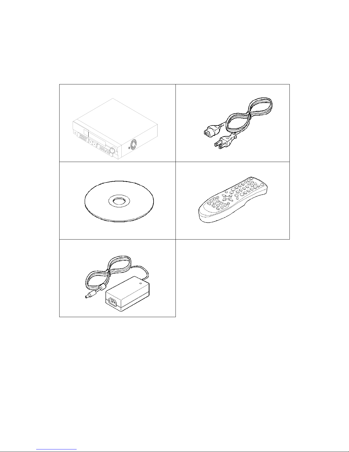
2. Supplied accessories
Unpack and check all the items as below;
1. eDVR MD800M (1EA)
2. AC Power Cord (1EA)
3. CD (Including Software) (1EA)
4. Remote Controller (1EA)
5. Power (applied adaptor) (1EA)
Page 9
9
3. Description & Function
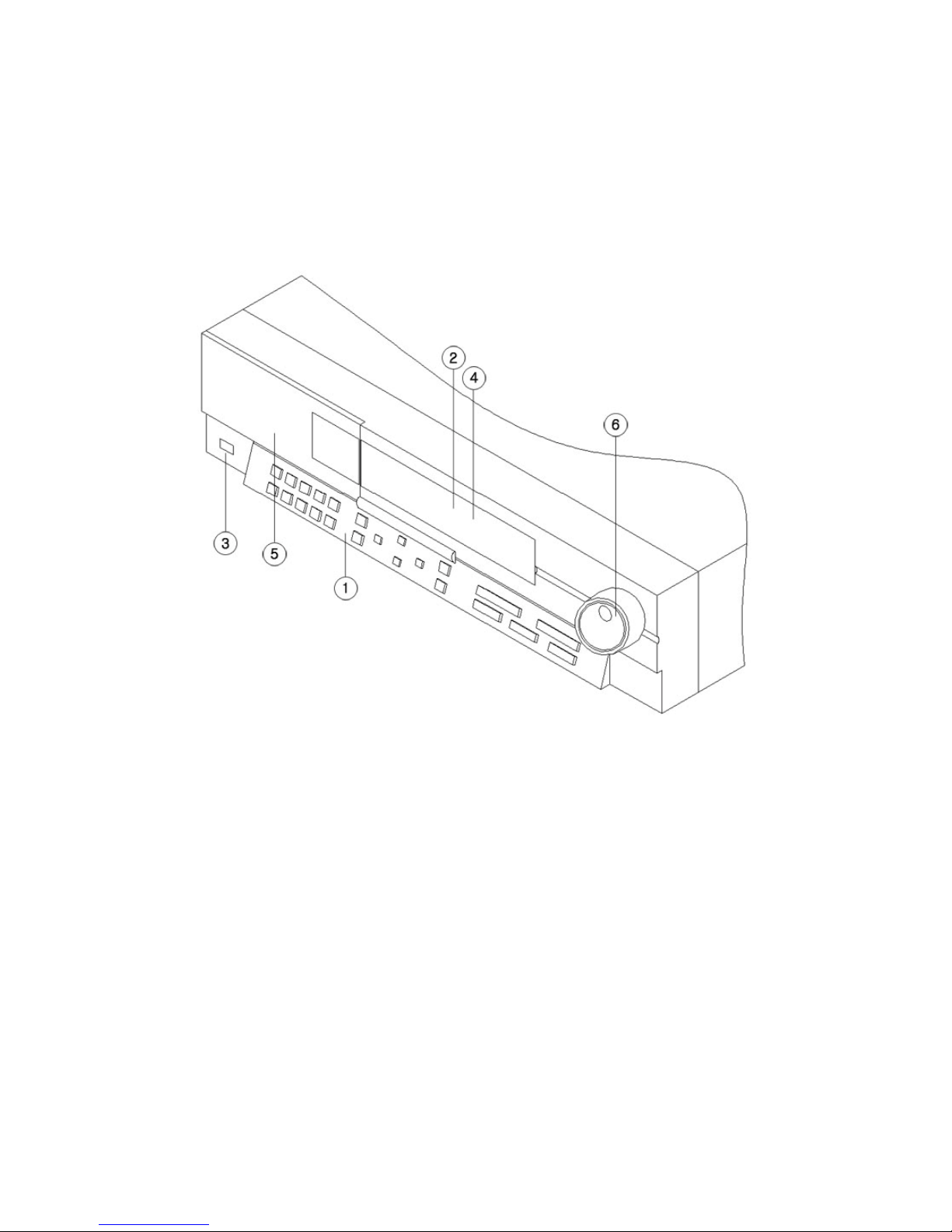
MD800M front
(1) Function buttons
(2) LED
(3) USB port
(4) Remote controller receiver
(5) CD/DVD-RW ROM
(6) Shuttle
Page 10
10
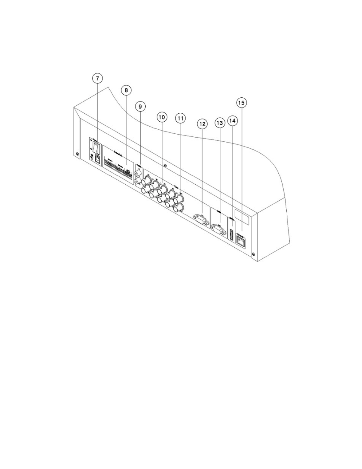
MD800M rear
(7) power connector
(8) Terminal block for sensor, relay, and serial input/output
(9) Audio input/ output connector
(10) BNC connector for video input
(11) BNC connector for video output
(12) VGA connector for video output
(13) Serial input/output
(14) eSATA connector
(15) Ethernet connector
Page 11
11
ISTALLATIO AD COECTIO
4. Connecting & Running
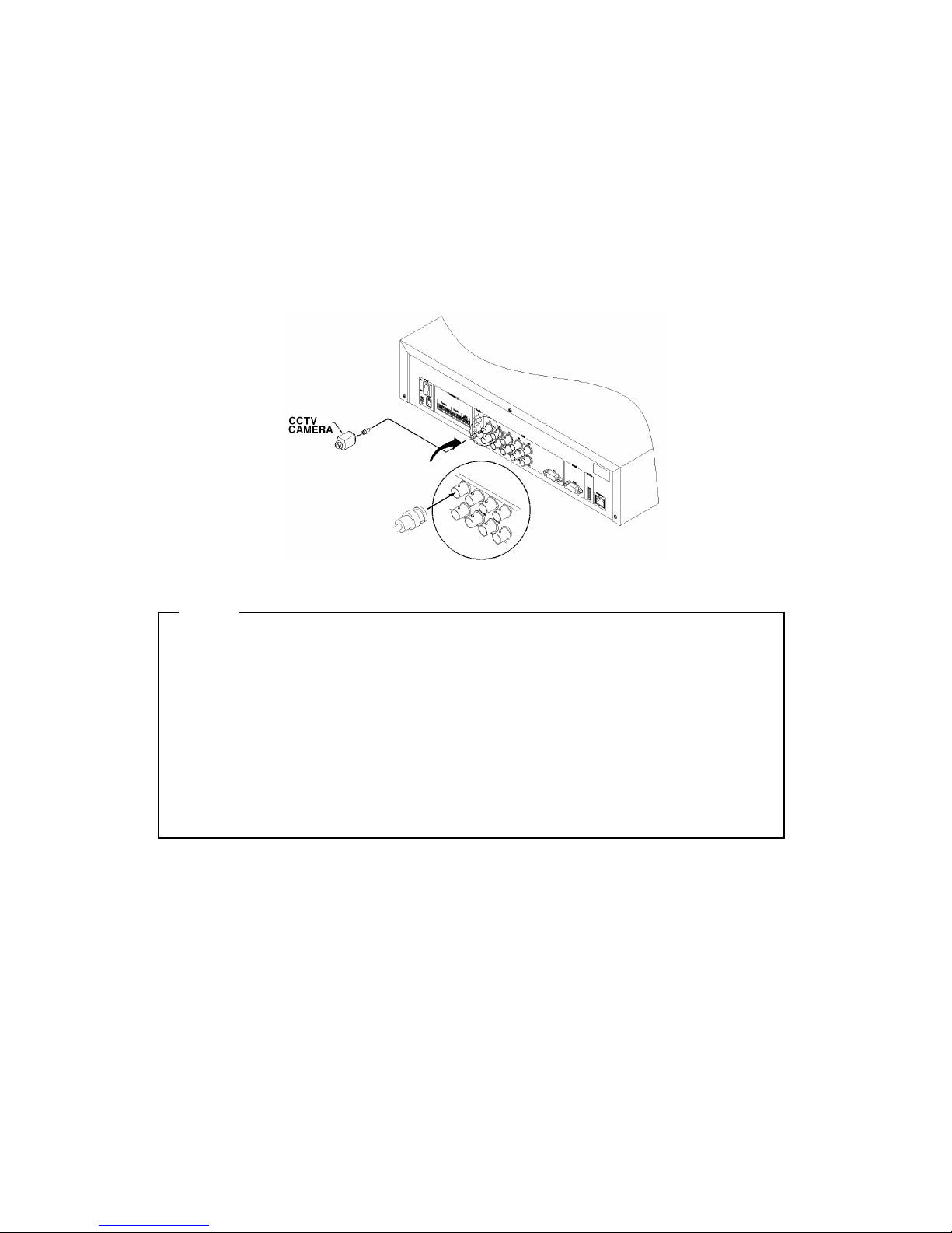
4.1. Connecting camera
(1) Connect CCTV camera to MD800M with BNC cable as below.
<ote>
1. The video type for all channels should be either NTSC or PAL, not be combined both.
2. MD800M sets video signal’s impedance (75Ω) automatically.
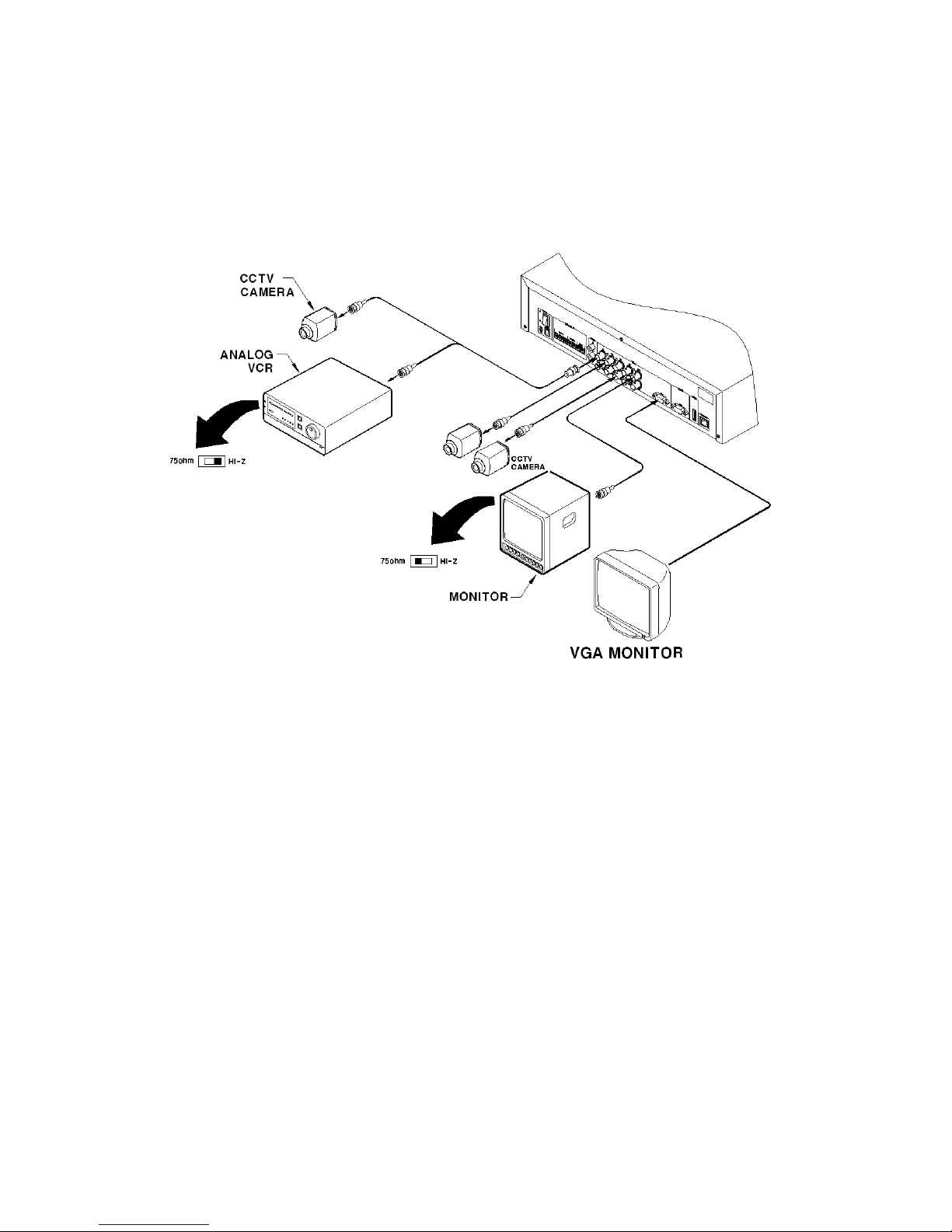
Impedance is set as 75Ω basically. If connecting a device to video output, impedance will be “Hi-
z” status. Please refer to “9.6 connecting Video In/Output” on page 12
3. Video Type(NTSC/PAL) should be changed after opeting MD800M. The order of camera
recognition follows Ch1 camera through Ch8 camera and 1st recognized camera type leads other
camera type.
Page 12
12
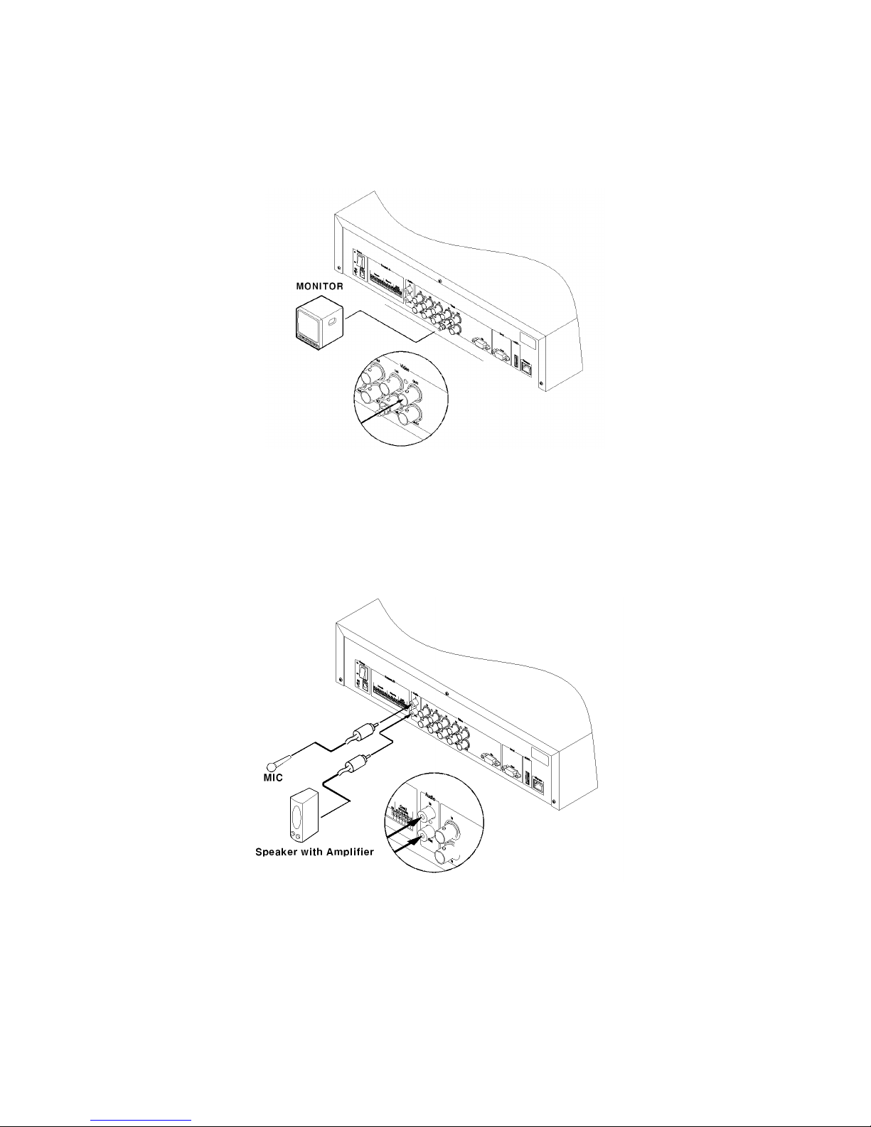
4.2. Connecting monitor
(1) Connect CCTV monitor to MD800M with BNC cable as shown below;
4.3. Audio Connection
(1) Connect auto signal to MD800M with using RCA cable.
Page 13
13
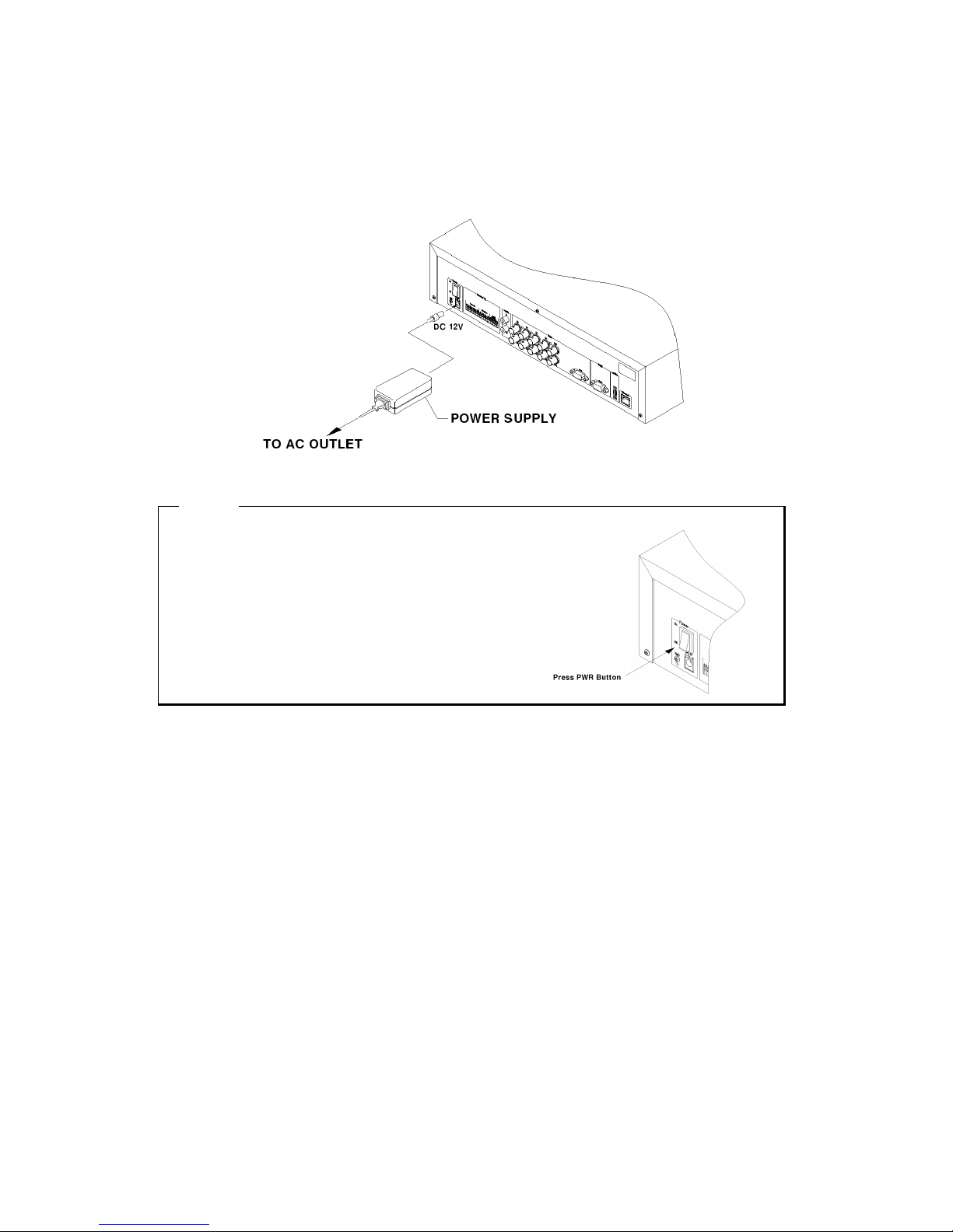
4.4. Power Supply
(1) Connect power cable as shown below
<ote>
1. When supplying power, MD800M starts booting
automatically.
2. In order to cut off power, press the power switch on
MD800M front during 4 seconds and enter admin
password after appearing a pop window.
3. For power supply again, push the power switch.
Page 14
14
5. Running OSD menu
5.1. Structure of Menu
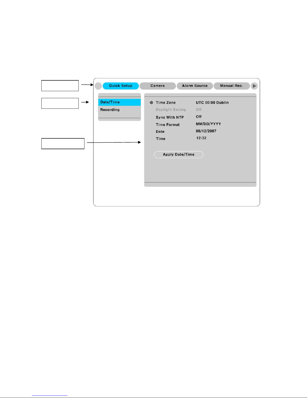
Press the [MENU] in keypad of front to open the OSD Configuration Menu
(1) Main Menu : The selected tab is shown in blue and the related sub-menu will be shown below the
tab. To movo to the previous/next Main Menu tab, use the [◀/▶] arrow buttons. To move to a sub-menu,
press the [▷]/[▼] arrow buttons.
(2) Sub-menu : The selected sub-menu is shown in blue and the relaed setting will be shown the right of
the sub-menu. Use the [▲/▼] arrow buttons to move within the sub-menu list. To move to the setting
page, press [▷] button. To exit the setting page, press the [EXIT] button.
(3) Setting Page : The selected sub-menu is shown as a circle on the left side of the name and gray color
for setting value. To move within each page, use the [◀/▶] or [▲/▼] arrow butons. Press the [▷]
button to change the value of a setting. When setting value is a word, a dialogue box to edit the word will
open. When setting value is a number, it should be set with using [◀/▶] or [▲/▼] arrow buttons. After
the value is set, press the [EXIT] button. To exit the Setting page, press the [EXIT] button.
①
Main Menu
②
Sub-menu
③
Setting Page
Page 15

15
5.2. Dialogue box to edit a word
There are two methods to input a word..
(1) Entering words
Move pressing [▶] arrow button to enter next word until the word is looking for is shown using [▲/▼]
arrow buttons. In case of spacing words, press [▶] to move one space and enter the word. To exit the
Dialogue box, press the [▷] arrow button.
(2) Available words range to use
1 2 3 4 5 6 7 8 9 0
A B C D E F G H I J K L M N O P Q R S T U V W X Y Z
a b c d e f g h i j k l m n o p q r s t u v w x y z
( ) - . $ # @
Page 16
16
6. Setting remote controller
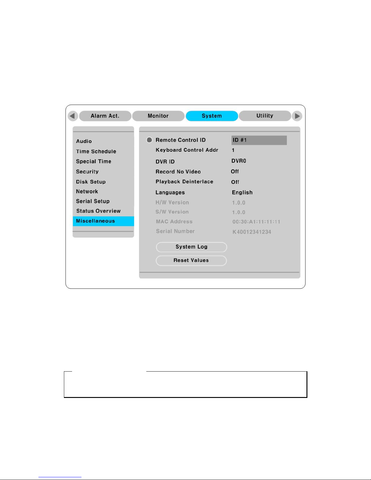
When controlling several eDVRs with one remote controller, set Remote Contorl ID as follows.
6.1. Setting ID of MD800M
(1) Press the [MENU] button
(2) Select “System” with using [▶] button and press the [▷] or [▼] button
(3) Select “Miscelleaneous” from the sub-menu list using the button[▼] and press [▷] button.
(4) Select “Remote Control ID” and press the [▷].
(5) Select a value using the [◀/▶] buttons and press the [EXIT] button.
(6) Press the [EXIT] button to exit the Settings Page and return to Monitor mode.
<ote> Remote Control ID
Up to 16 eDVRs can be controlled with a single remote controller.
When not using remote controller, set the Remote Control ID as “Off”.
Page 17
17
6.2. Selecting MD800M
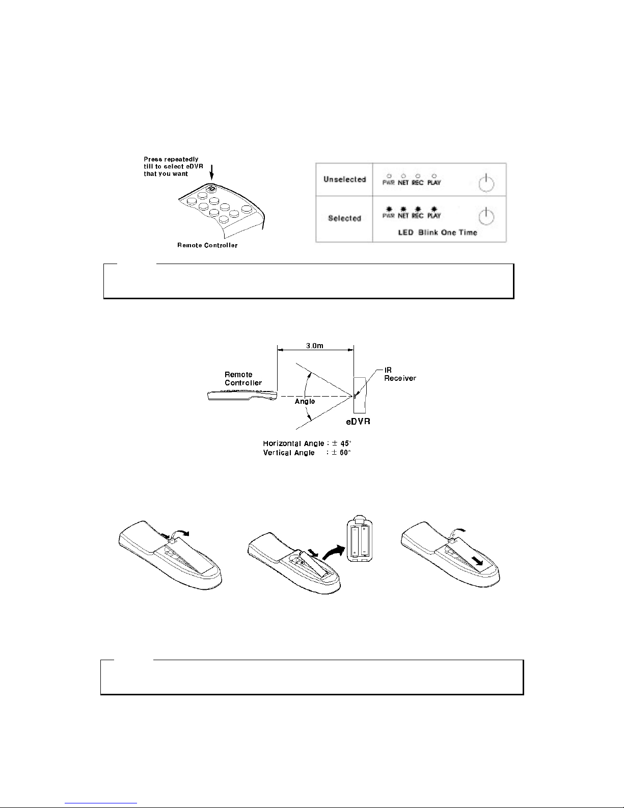
If several eDVRs are set with unique ID numbers, they can be controlled with one remote controller. To
select a specific eDVR (MD800M), Keep pressing the ID button of remote controller until a buzzer
sounds during 2 seconds.
<ote>
Because remote controller ID is sixteen, eDVR will correspond until pressing ID button sixteen times.
6.3. Operable range of remote controller
6.4. Loading the batteries into remote controller
Remote Controller requires two AAA-type batteries
1. Remove the battery cover
2. Taking care that the poles(+/-)
Are correctly positioned.
3. Replace the battery cover
<ote>
Batteries are not included as a packing accessory
Page 18
18
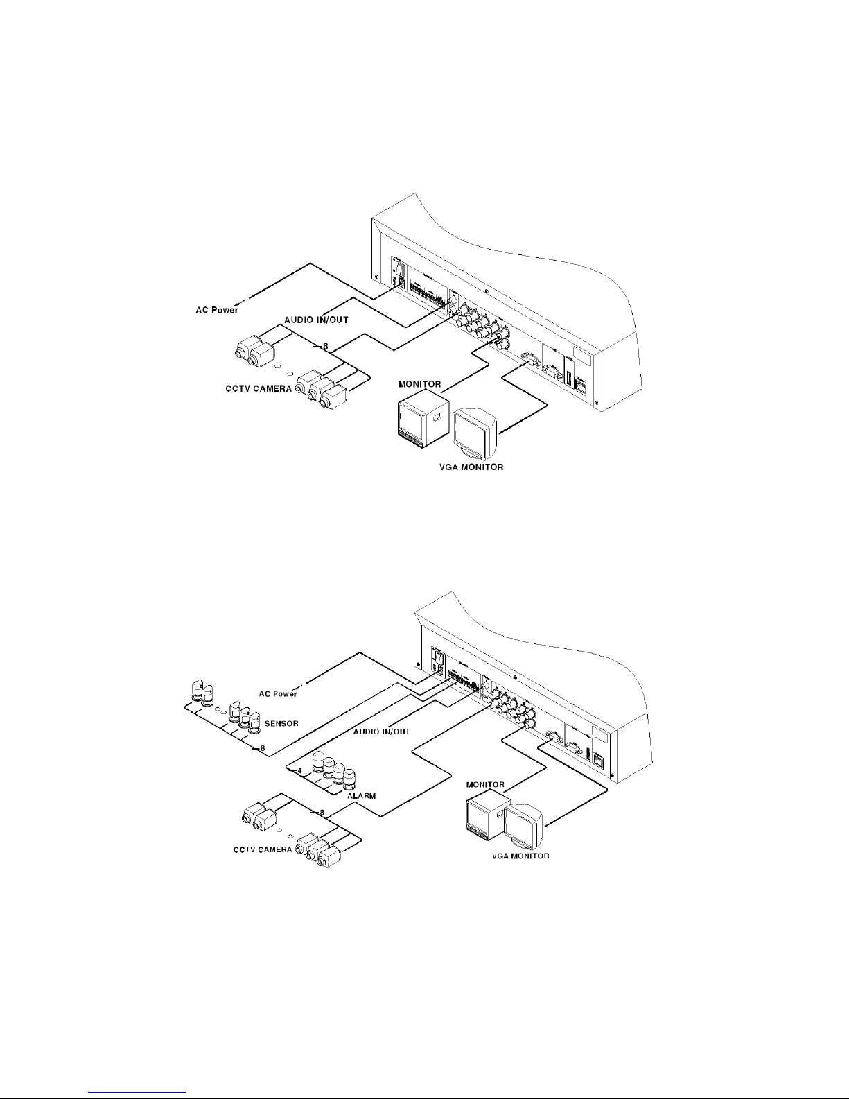
7. MD800M configuration
7.1. Basic Configuration
7.2. Advanced configuration
Page 19
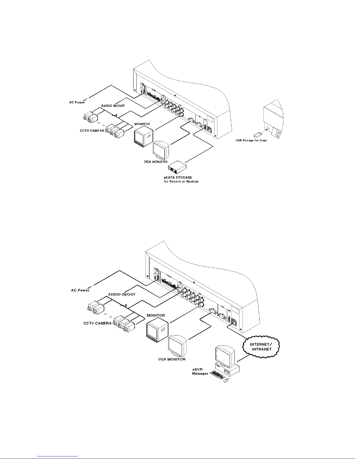
19
7.3. External storage & Back up configuration
7.4. Internet/ Intranet configuration
Page 20
20
8. eDVR MD800M basic setting
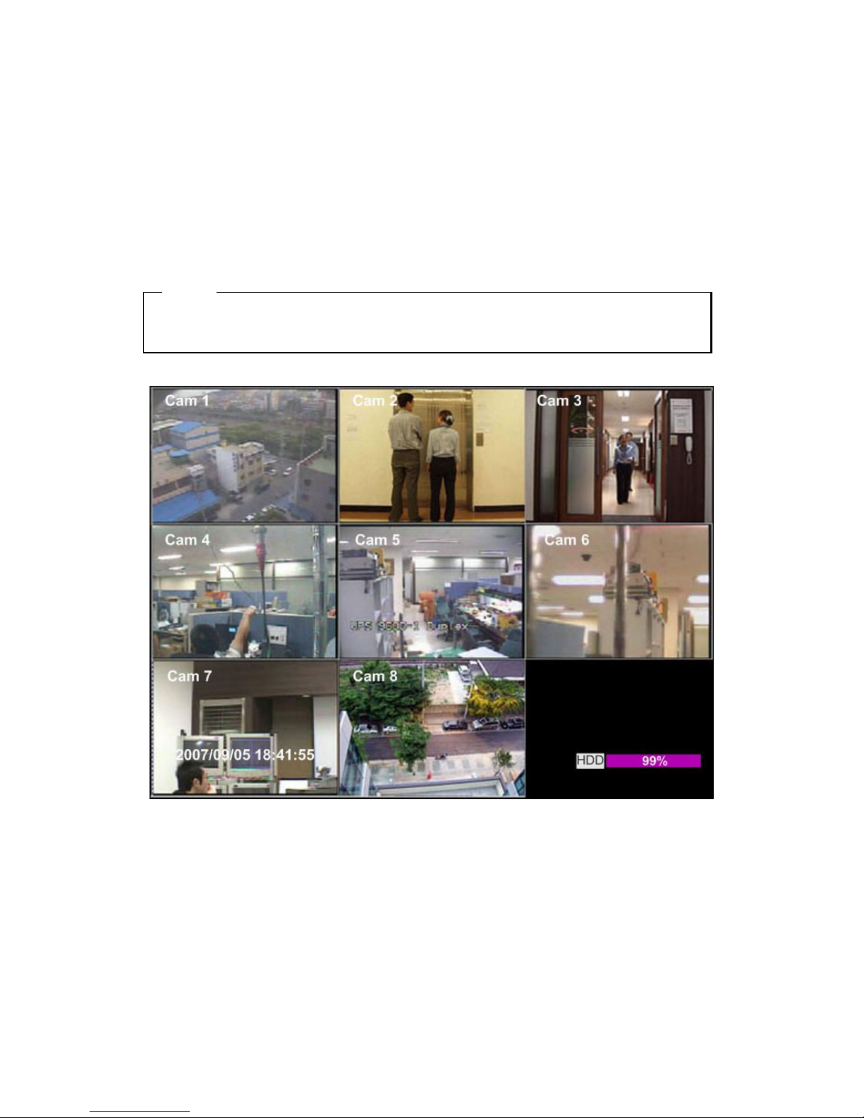
8.1. Viewing Image
When power is on, MD800M starts automatically and images are displayed in basic 9division screen after
the booting.
<ote>
If user password is set, a prompt for entering the password will appear. Facotry default is reserved as
not responding key pad on eDVR front (It is not set from factory default)
Page 21
21
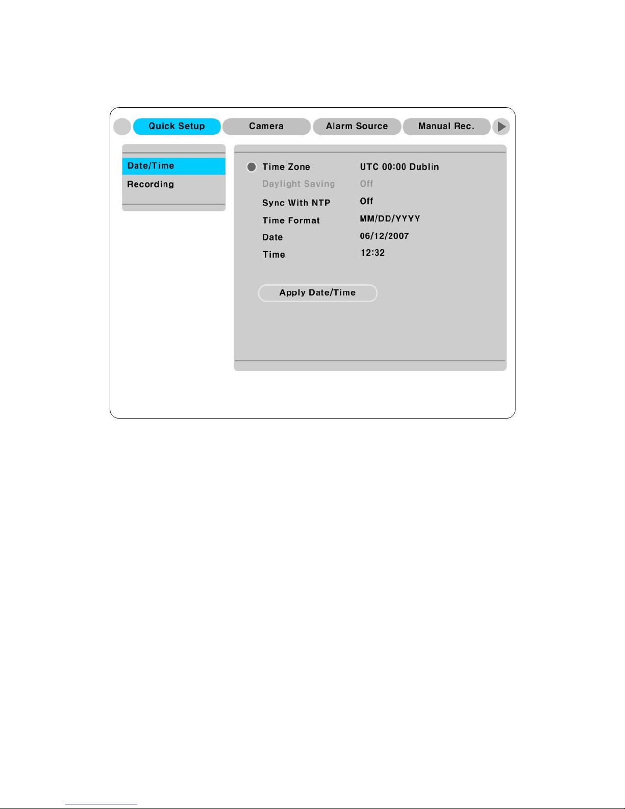
8.2. Setting Date & Time
(1) Press [MENU] button and select “Quick Setup” tab.
(2) Select “Date/Time” using the [▷] or [▼] and press [EXIT] button.
8.2.1. Time Zone
(1) Select “Time Zone” using the [◀/▶] or [▲/▼] buton and press [▷] to configure.
(2) Select Time Zone using the [◀/▶] button and press [EXIT].
8.2.2. Daylight Saving
(1) Daylight Saving Time is only activated for Time Zone that uses Daylight Savings.
(2) Select “Daylight Saving” using the [◀/▶] or [▲/▼] button and press [▷] button.
(3) [◀/▶] Select On/Off using the [◀/▶] and press [EXIT].
8.2.3. Sync with TP
In order to synchronize time with NTP (Network Time Protocol) server, select “on”.
(1) Select “Sync with NTP” using the [◀/▶] or [▲/▼] button and press [▷] button.
(2) Select On/Off using the [◀/▶] button and press the [EXIT] button.
Page 22
22
8.2.4. Time Format
(1) Select “Time Format” using the [◀/▶] or [▲/▼] button and press [▷] button..
(2) Two time formats are available; ‘DD/MM/YYYY,’ ‘MM/DD/YYYY’, ‘YYYY/MM/DD’; Select a
value using [▲/▼] buttons and press the [EXIT] button when it is finished. (Factory default is set as
‘MM/DD/YYYY’)
8.2.5. Date
(1) Select “Date” using the [◀/▶] or the [▲/▼] buttons and press [▷]. Select ‘MM’, ‘DD’, ‘YYYY’
using the [◀/▶] buttons.
(2) Press the [EXIT] button when setting is finished.
8.2.6. Time
(1) Select “Time” using the[◀/▶] or [▲/▼] buttons and press [▷].
(2) Select ‘HH’, ‘MM’ using the [◀/▶] buttons, and select the value using the [▲/▼] button.
(3) Press the [EXIT] button when setting is finished.
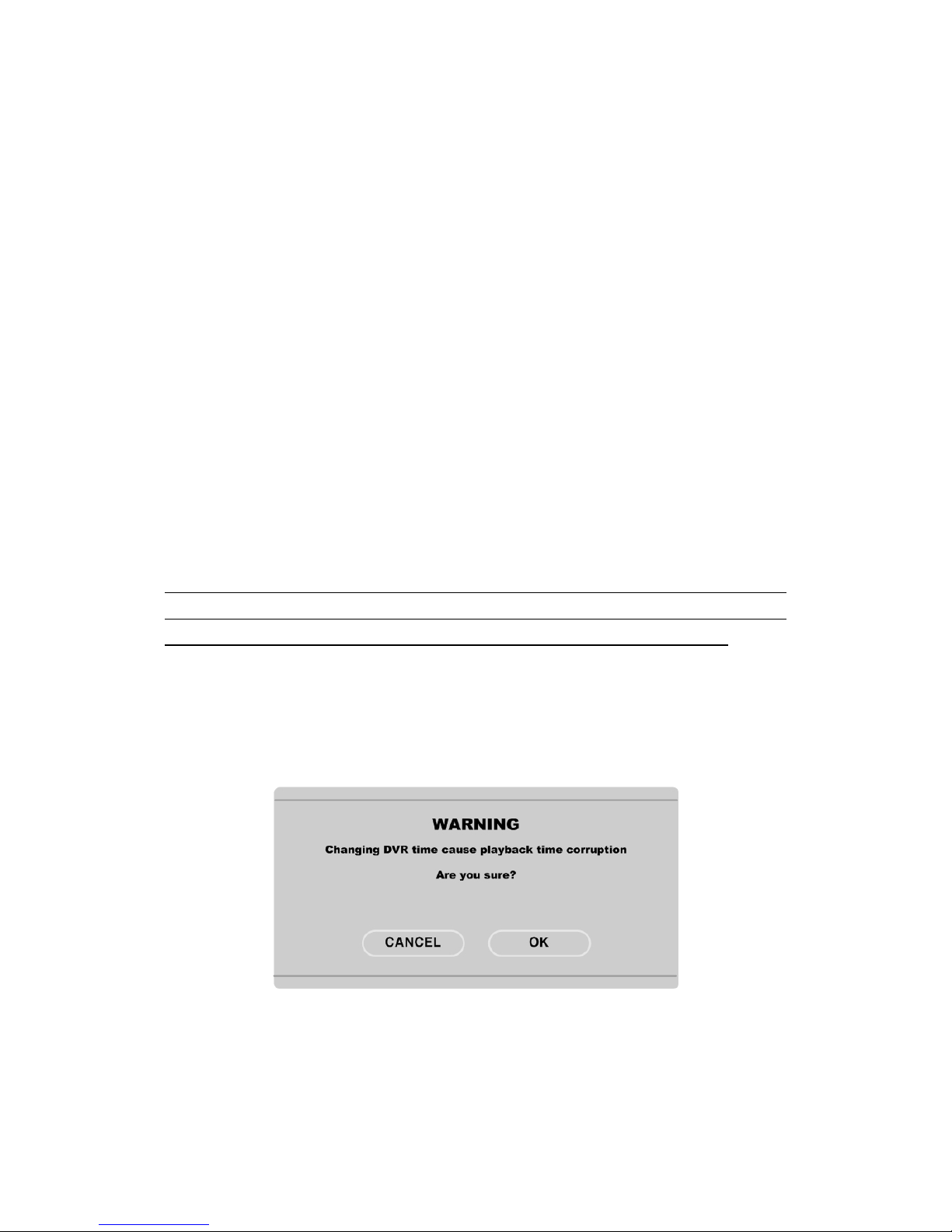
8.2.7. Apply Date/Time
Most setting values are applied automatically, when exiting from the related menu page. But “Date”
& “Time” setting are not applied automatically because they may critically affect the file system of
the recorded HDD. To apply Date/ Time settings confirm with [Apply Date/ Time] buttons.
(1) Select “Apply Date/time” using the [◀/▶] or [▲/▼] buttongs and press [▷]. A warning message
will be appeared will be appeared as below;
(2) Select “OK” using [◀/▶] or [▲/▼] buttons and press [ENTER] button. To cancel, press the [EXIT]
button.
Page 23
23
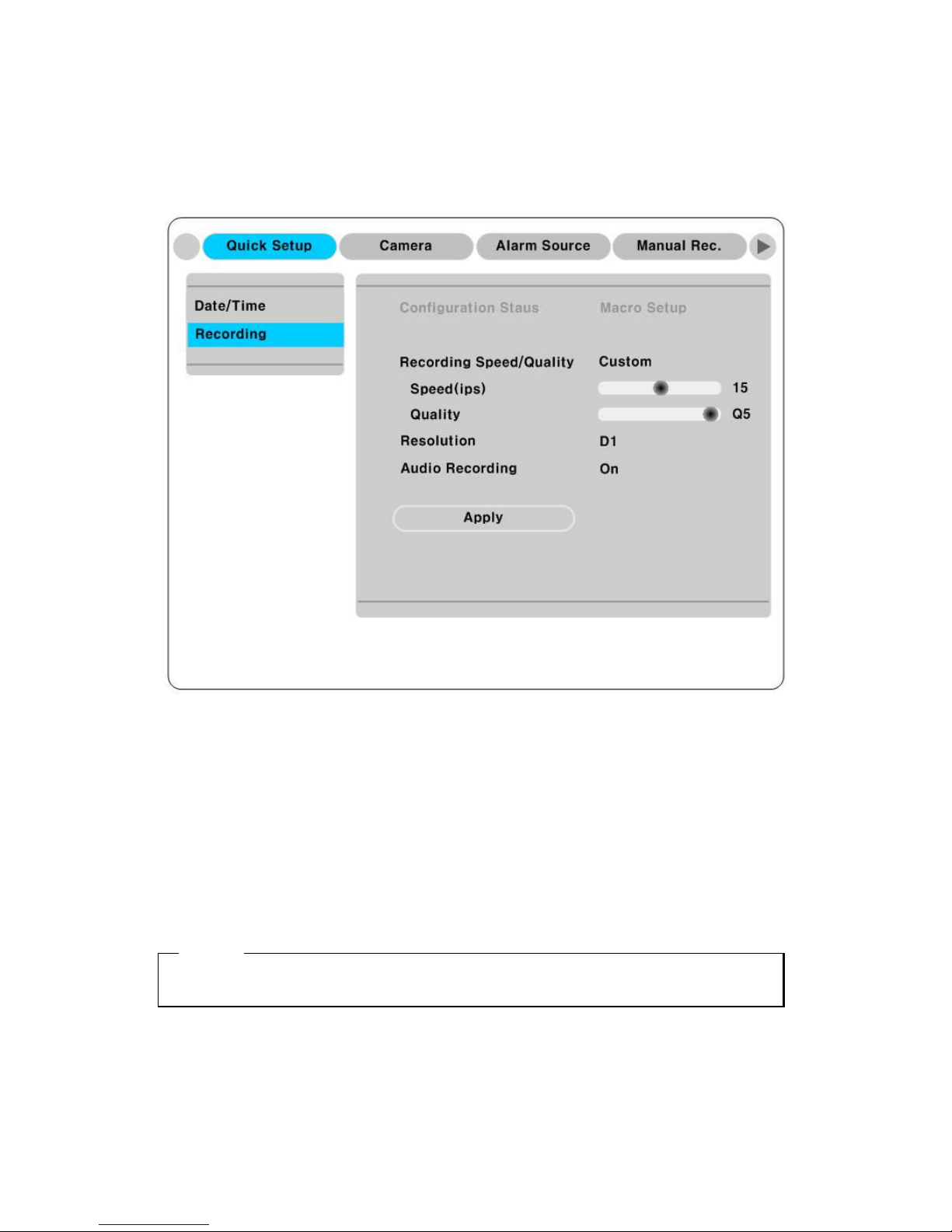
8.3. Setting recording condition
Recording conditions under the “Quick Setup” menu tab apply the same values to all analog channels 1~8.
All settings are applied for 24 hours/ day regardless of the value set for “Time Schedule” or “Alarm Rec.”
(1) Press [MENU] button and select “Quick Setup” when OSD menu is shown.
(2) Move to sub-menu by pressing [▷] or [▼] button.
(3) Select “Recording” using the [▲/▼] buttons and press [▷].
8.3.1. Configuration Status
Displays the recording configuration status. When setting through the “Quick Setup” menu, “Quick
Setup” will be shown. When setting up thorugh “Normal Rec,” or “Alarm Rec,” “Custom Setup” will be
shown.
<ote>
Only when normal recording of all channels are same, it is marked as ‘Macro Setup’.
Page 24

24
8.3.2. Recording Speed/Quality
(1) Select “Recording Speed/ Quality using [▲/▼] buttons and press [▷].
(2) Select a value using the[◀/▶] button. Press the [EXIT] button when it is finished.
8.3.3. Speed(ips)
When “Recording Speed/Quality” is set as” Custom”, values can be set manually.
(1) Select “Speed” using the [▲/▼] button and press [▷].
(2) Select a value using the [◀/▶] button. Press the [EXIT] button when it is finished.
8.3.4. Quality
When “Recording Speed/Quality” is set as “Custom”, values can be set normally.
(1) Select “Quality” using the[▲/▼] button and press [▷].
(2) Select a value using the [◀/▶] button. Press [EXIT] button when it is finished.
8.3.5. Audio Recording
(1) Select “Audio Recording” using the[▲/▼] buttons and press [▷].
(2) Select a value using the[◀/▶] button and press [EXIT] button when it is finished.
8.3.6. Alarm Recording
(1) Select “Alarm Recording” using the[▲/▼] buttons and press [▷].
(2) Select a value using the[◀/▶] button and press [EXIT] button when it is finished.
8.3.7. Apply
(1) Select “Apply” using [▲/▼] buttons and press [▷].
(2) Setting values are applied and the prevous menu will be displayed.
Page 25
25
9. Connecting and configuring DIO ports
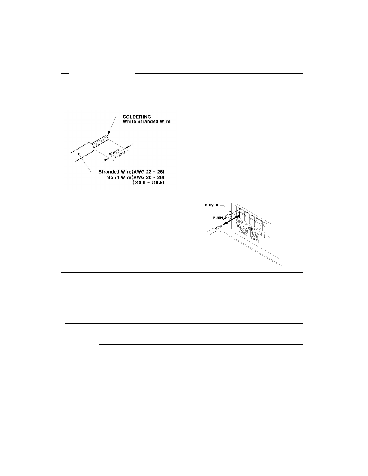
<ote> Wire Handling
Trimming Wire
When connecting a wire to a terminal block, follow the instructions below. Note the different types of
wire that can be used.
Standard Wire : Peel off the wiring, cover
8~10mm and solder it. Wire gage should be
AWG 22~26.
Solid Wire : Peel off the wiring cover 8~10mm
and solder it. Wire gage should be AWG 20~26
Inserting & removing wire
To insert & remove wirte in TERMINAL BLOCK,
use a screwdriver in the diagram to the right.
9.1. Connecting and configuring sensor
9.1.1. Specification
In order to run sensor input of eDVR MD800M normally, the following conditions are required.
Spec.
Input Ch. 8Ch Transister inputs
Input type N.C (Normal Close)/ N.O. (Normal Open) type.
Supported sensor Dry contact sensor
Connecting Connecting the trimmed wire to terminal block
Performance
Available input pulse range Min. 500ms
Output current Typical DC 12mA
Page 26
26
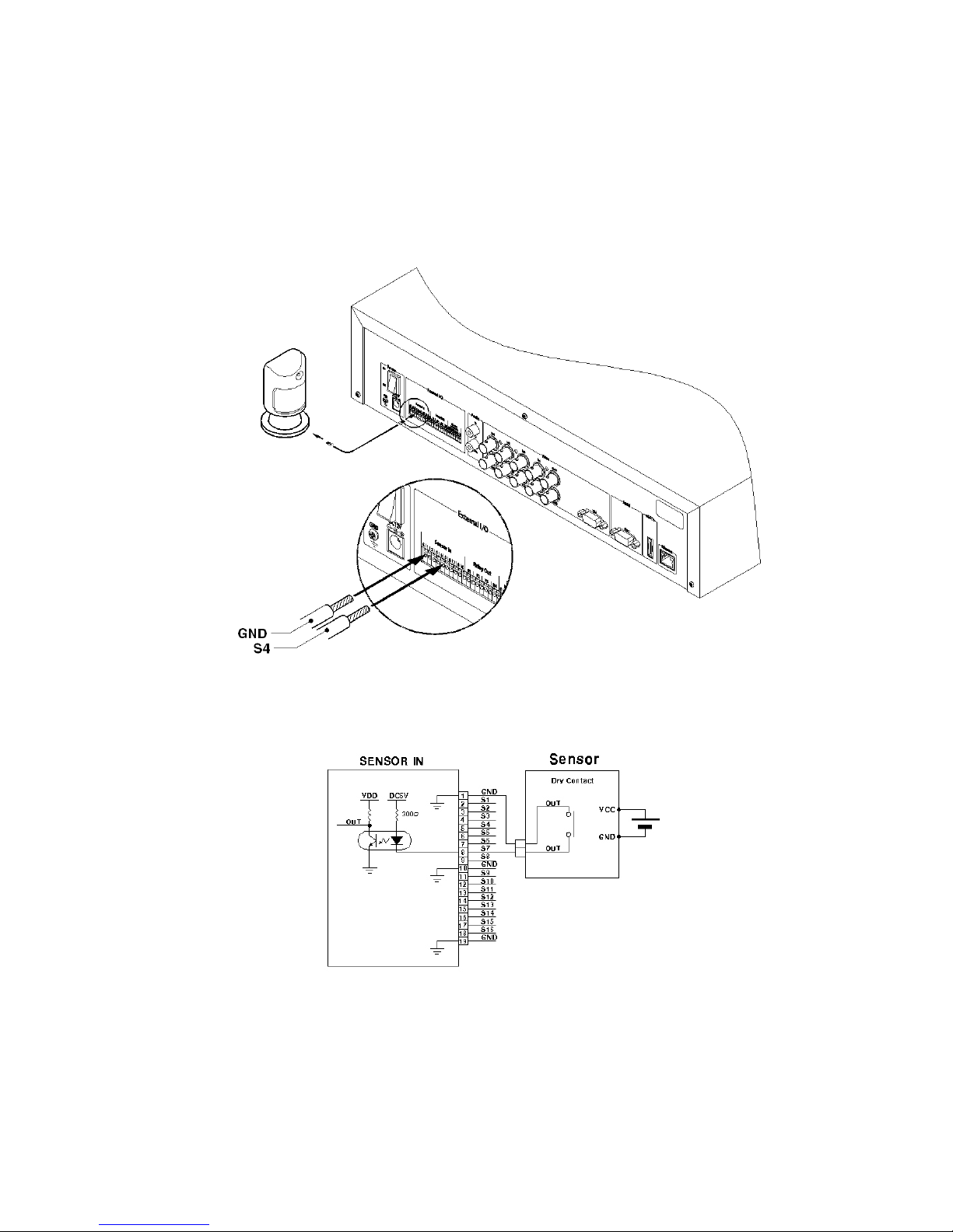
9.1.2. Connecting sensor input
Connect S1 ~ S8 with referring to the followings. It shows to connect a dry contact (Please refer to
“<ote> Wire Handling” on page 27). When connecting a non-dry contact type of sensor (e.g. Open
collector output) please contact WEBGATE’s customer Support team.
Page 27
27
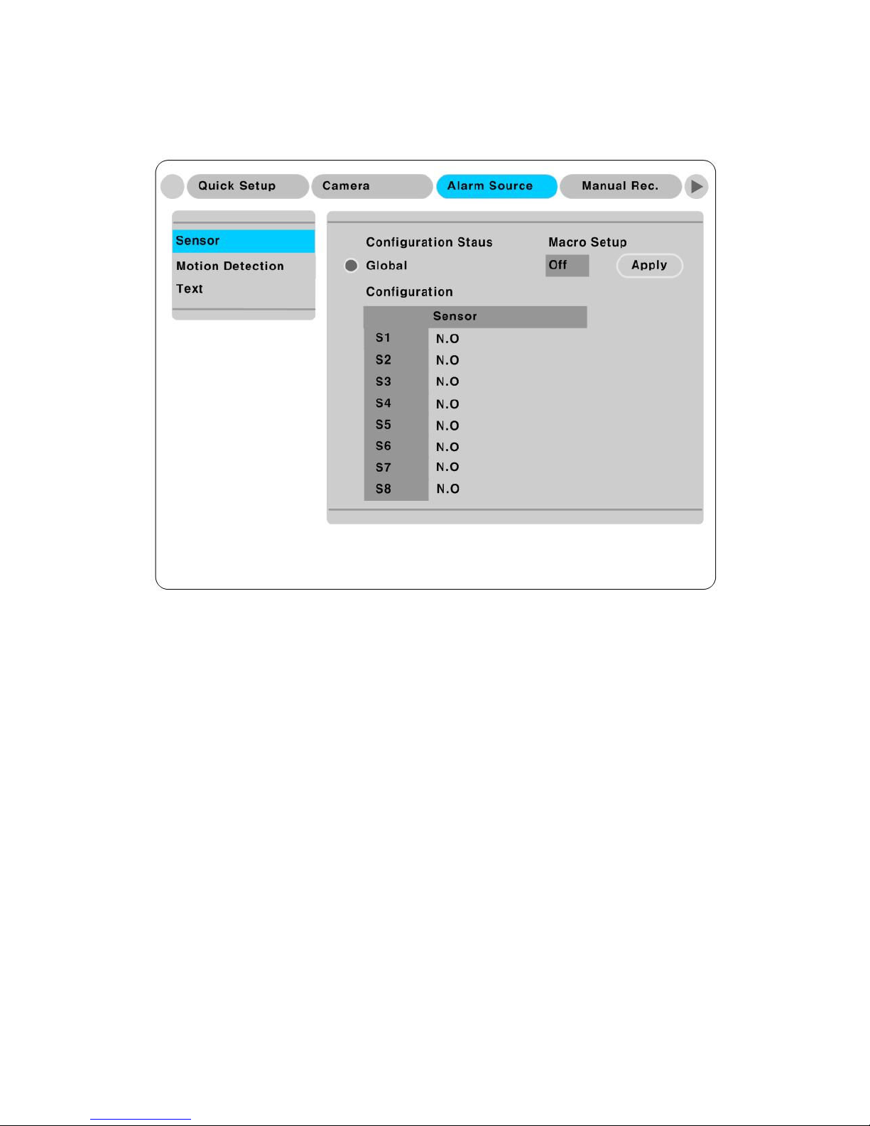
9.1.3. Configuring Sensor at OSD menu
(1) Press the[Menu] button and select “Alarm Source”.
(2) Press [▷] or [▼] button to move to Sub-Menu, select “Sensor” and press [▷].
9.1.3.1. Global
Use when selecting all 8 sensors simultaneously, which can be selected as “Do not use”(Off). “Normal
Open” (N.O), and “Normal Close” (N.C.).
(1) Select a “Global” and set a type as Off, N.O. or N.C...
(2) Press “Apply” to save a configuration
9.1.3.2. Configuration
Use when selecting each 8 sensor individually.
(1) Select a “Confiugration” and press [▷].
(2) Select a sensor (S1 ~ S8) and set a type.
(3) Press [Exit] to out from OSD Menu.
Page 28

28
<ote>
1. Configuration a sensor is to set On/Off usage and type.
2. Please refer to “Alarm Rec” for saving and “Alarm Act” for relay-out on the “eDVR User’s Guide”
9.2. Connecting & configuring relay out
9.2.1. Specifications
In order to run relay output of eDVR MD800M normally, the following conditions are required.
Spec.
Output Ch. 4Ch relay differential outptus
Output type Dry Contact
Connecting type Connect the trimmed wire to terminal block
Rated
Voltage
DC 24V DC, 1.25A, 30W
125V DC, 0.24A, 30W
AC 125V AC, 0.5A, 62.5VA
250V AC, 0.25A, 62.5VA
Page 29
29
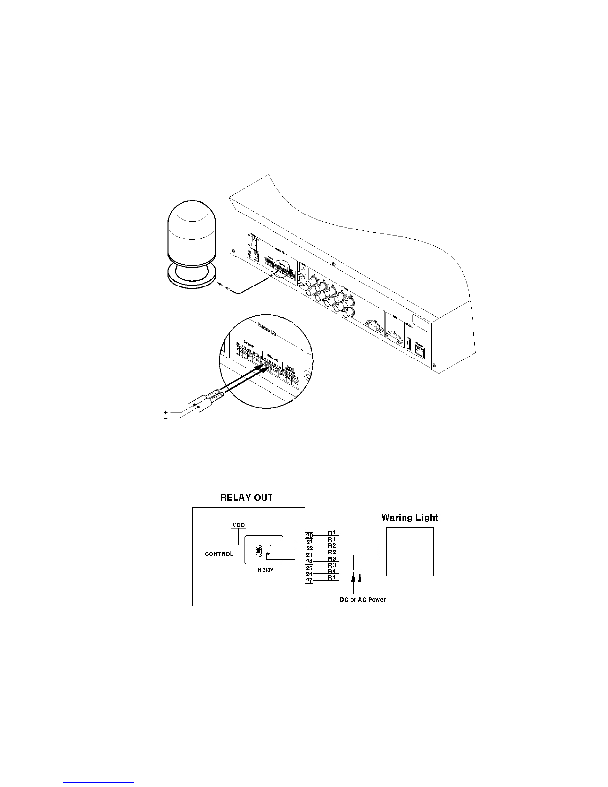
9.2.2. Connecting Relay Out
Connect R1 ~ R4 with referring to the followings, It shows how to connect a Warming light. Please refer
to “ <ote> Wire Handling” on page 25.
Page 30
30
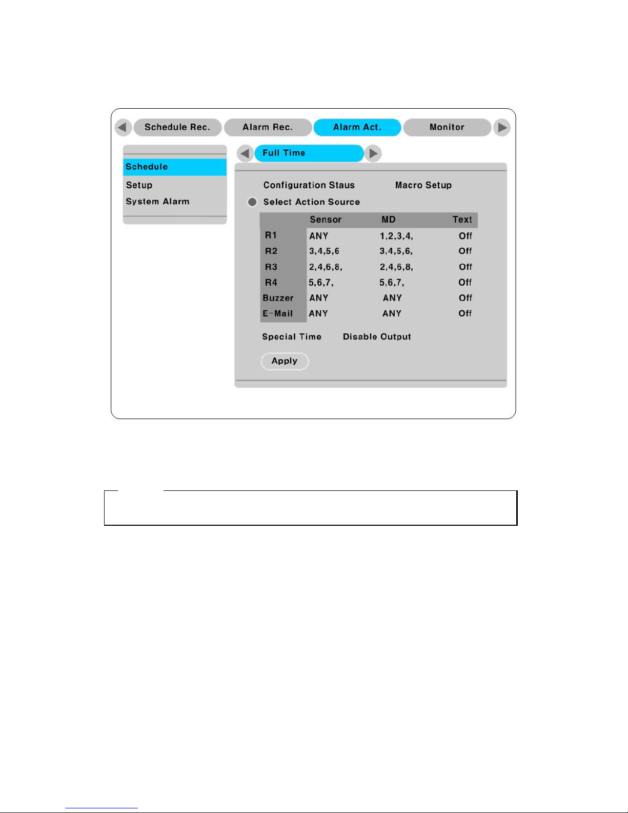
9.2.3. Configuring relay out as OSD menu.
Relay can run by sensor or MD and its condition can be set differently according to schedule. When using
the [Relay] button + [Number] button on the front panel or Control Center Lite-D S/W, relay can be
operated from remote site.
<ote>
Please refer to the “eDVR User’s Guide” for more information.
Page 31
31
9.3. Connecting serial port
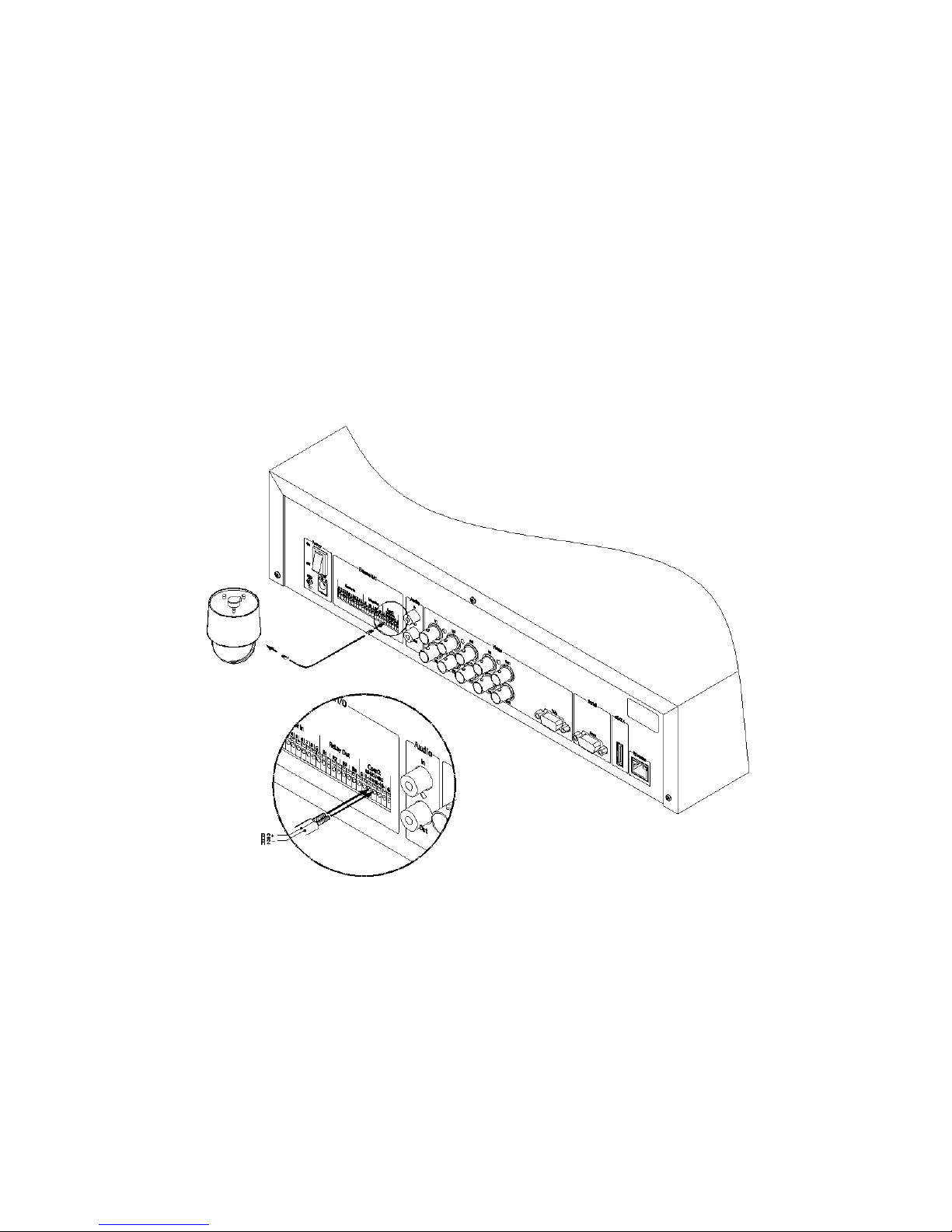
9.3.1. Configuring Serial ports for Pan/Tilt/Zoom
The MD800M have most major PTZ protocols already pre-programmed. Makes and models not
supported can still be controlled using the Transparent Protocol. For a list of supported protocols, refer to
the list on the OSD Configuration menu.
The following figure shows how to connect PTZ camera to RS485 (COM2). When using another serial
port, connect it with referring to each connection diagram below.
Please refer to the “<ote> Wire Handling” on page 27.
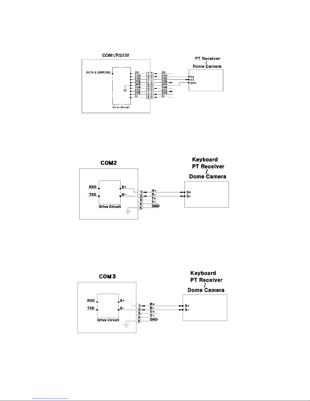
9.3.2. Diagram of serial ports
Page 32
32
9.3.2.1. Diagram of COM1(RS232)
9.3.2.2. Diagram of COM2(RS485)
9.3.2.3. Diagram of COM3(RS485)
Page 33
33
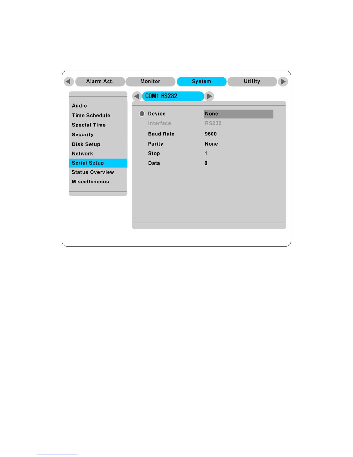
9.3.3. Configuring Serial
Configure PTZ COM ports and available models at “System/ Serial Setup” in MD800M.
After completing serial setup, configure base address or port for each channel at “ Camera menu” tab.
When connecting PTZ devices to several cameras, be sure base address matches address for the camera.
Page 34
34
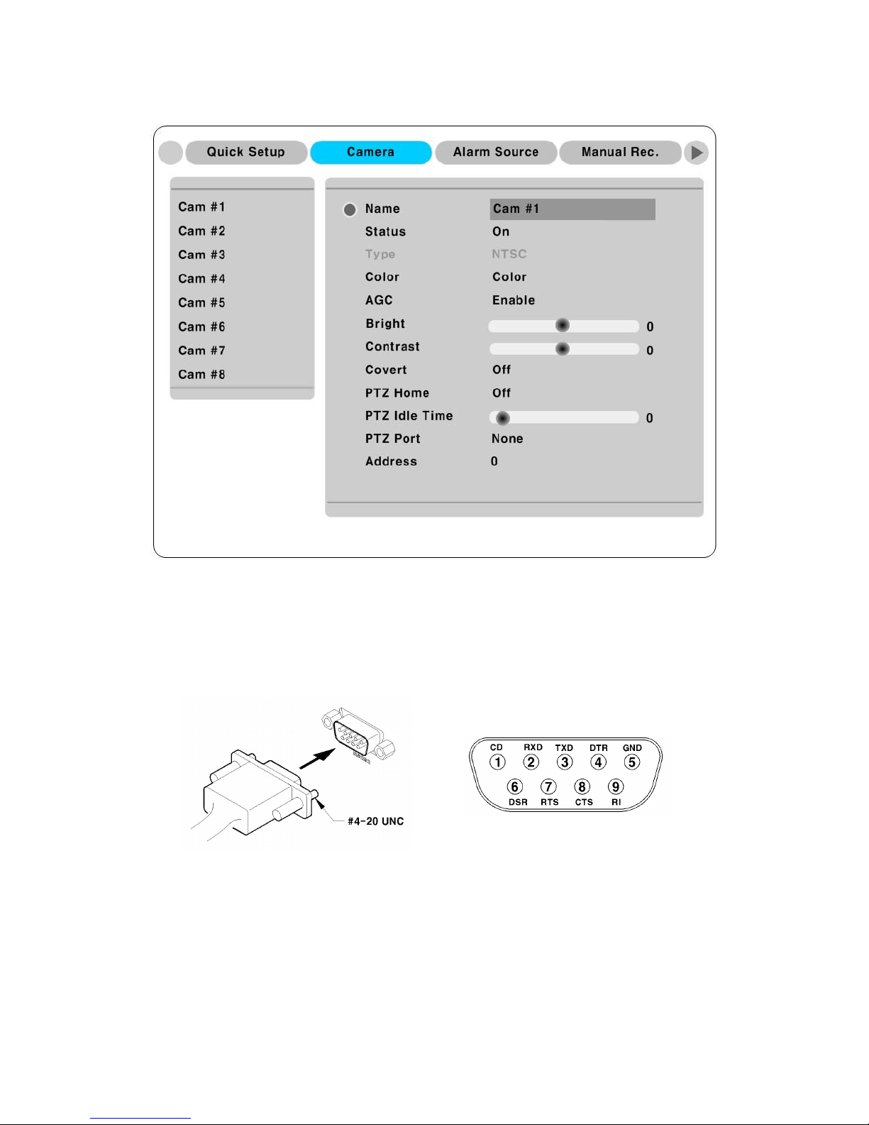
9.4. Connecting external device with serial port
9.4.1. Connecting text inout device (ATM / POS / Access Control)
The MD800M can record text data received from POS/ATM through the COM/RS232 serial port.
Connect to COM1/RS232 (9Pin D-Sub) of MD800M and configure the “Serial Setup” sub-menu under
the “System” tab and “Text” sub-menu under the “Alarm Source” tab shown as above figure.
Page 35
35
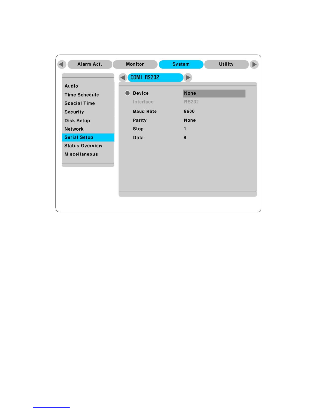
9.4.2. Configuring serial setup (COM1) at OSD menu
(1) Set the “System” in OSD menu and move to “Serial Setup” menu.
(2) Select COM in “Serial Setup”, set Devices as “Text”.
(3) Set Baud Rate/ Parity/ Stop bit with referring to manual of the connected external device.
Page 36
36
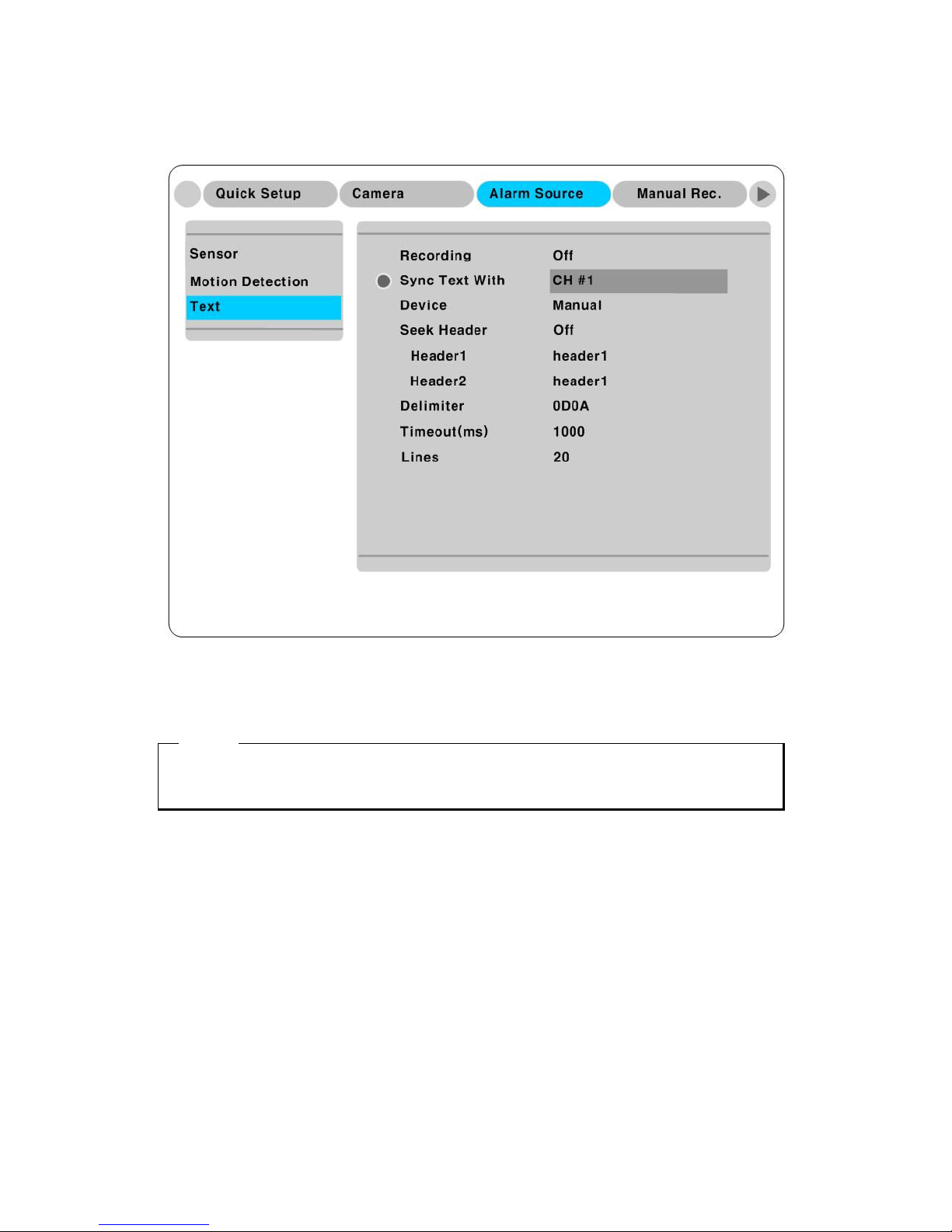
9.4.3. Configuring text
(1) Select the “Alarm Source” menu among OSD menus.
(2) Select the “Text” and set each value.
<ote>
Before installing any external device, consult with the local WEBGATE distributor. Some external
devices may not be compatible with the eDVR.
Page 37
37
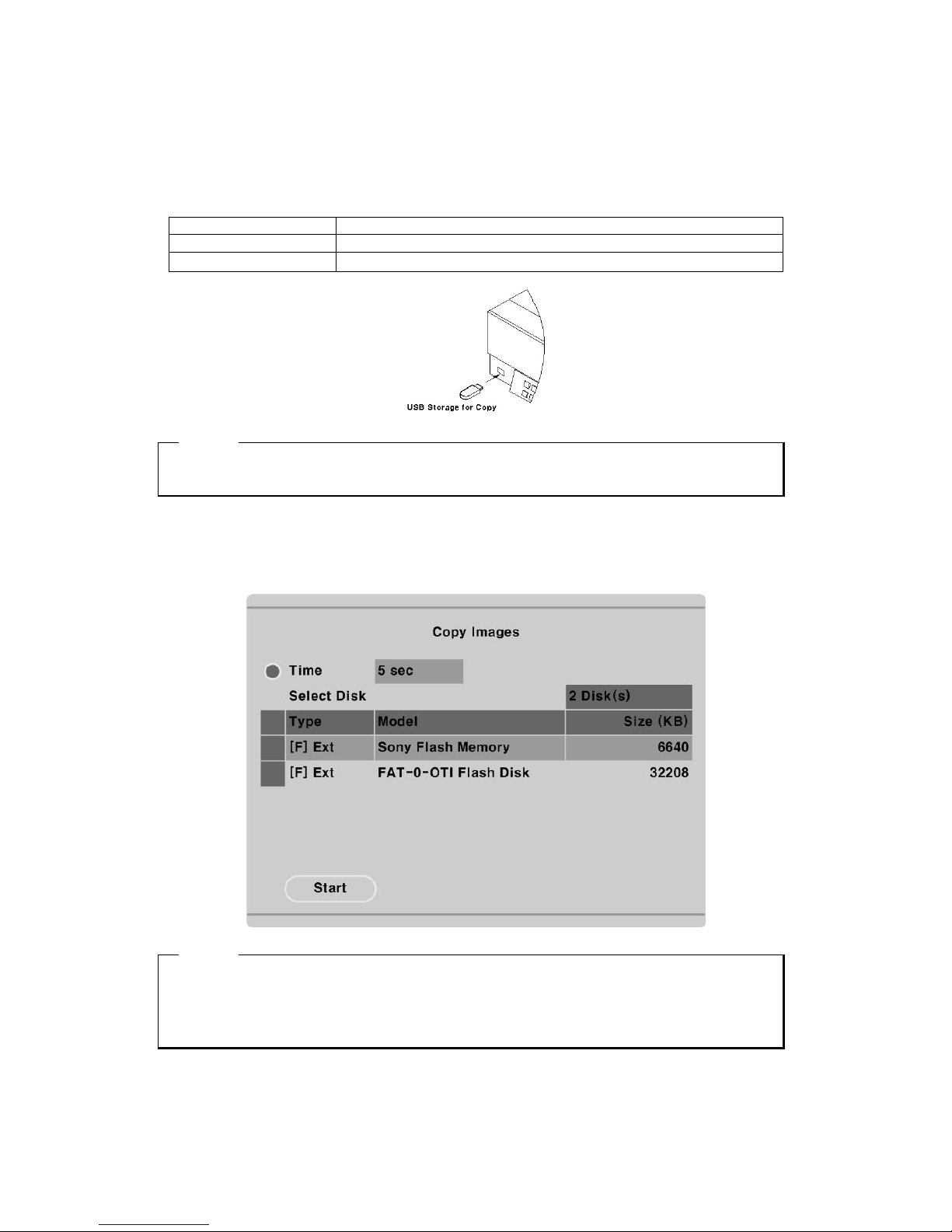
9.5. Connecting USB device
USB port can be used to copy up to 1 minute of images to a USB Flash memory disk. When connecting
USB Device, do not exceed the rated values of USB device as below;
USB Spec. Ver 1.1 (Max 12M bps)
Available Device USB Memory Stick,
Output Voltage/Current Max. 200mA per DC 5V/ Port
<ote>
The disk should be formatted with FAT32 type.
If properly connected the disk is recornized automatically as in the following pricutre. To copy images the
process is as follows; Set copy range (up to 1minute) Select drive Copy
<ote>
1. USB Flash products that required a Windows program to operate may not be recognized by the
eDVR
2. For more information about copy function, please refer to the “eDVR User’s Guide”
Page 38
38
9.6. Connecting Video in/output
Page 39
39
10. Connecting External Storage
10.1. eSATA port
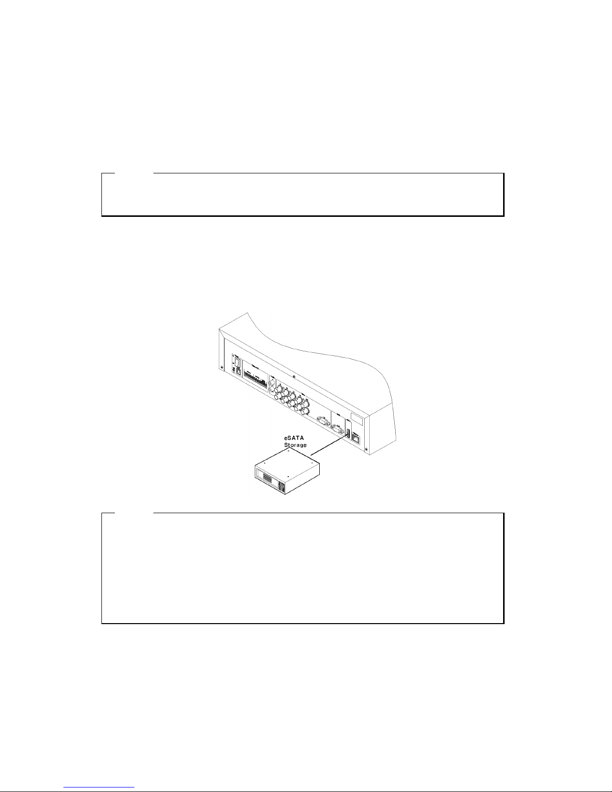
MD800M have two eSATA ports (Rear: 1-ports) for external storage device interface.
<ote>
Some eSATA may not be recognized by the MD800M according to the method. Before purchasing,
please consult with the local distributor.
10.2. Connecting eSATA Device
When using external eSATA supporting FireWire, hard drive bays can be connected through 1 port in the
rear panel. MD800M do not supply power to the hard drive bay; therefore the device using external
power is only available.
<ote>
While operating MD800M, it can recognize eSATA connecting. But it may not recognize based on
external device. It recommends the connection in following orders;
1. Power off MD800M
2. Connect external device and eSATA interface cable.
3. Power on external device
4. Power on MD800M
Page 40
40
10.3. Available HDD
It is recommended to use following HDD models with the MD800M. If a non-recommended HDD is
used, WEBGATE Inc. will guarantee the warranty.
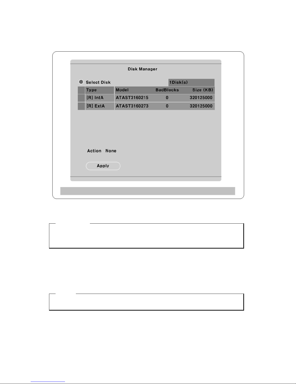
10.4. Registering & Formating HDD
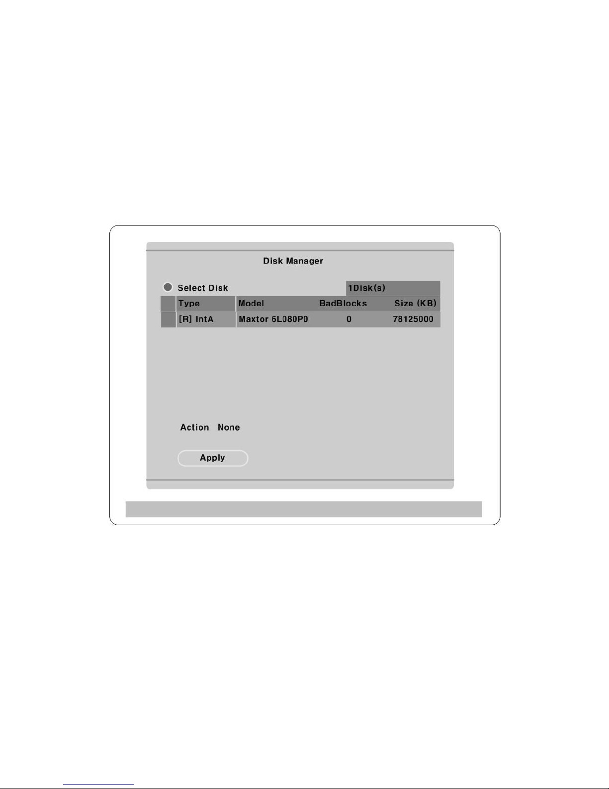
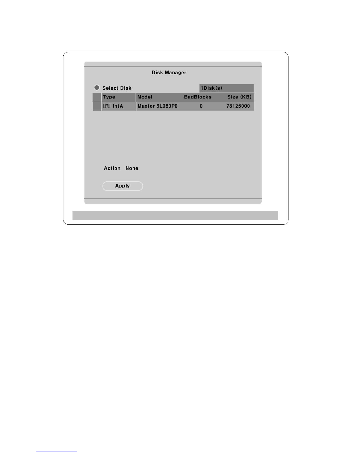
“Disk Manager” will automatically run on start-up installing a HDD as below;
If “Disk Manager” deos not automatically run on start-up, make sure the HDD is properly installed.
(1) Press [▷] button marked at “Select Disk”.
(2) Select new added HDD(indicated as “[F]”) using [▲/▼] button and press [EXIT].
(3) Select “Action” using [▲/▼] button and press [▷].
(4) Select “Add” using [◀/▶] button and press [EXIT].
(5) Select “Apply” using [▲/▼] button and press [▷]. The HDD status is changed to “[*]”.
(6) Select “Action” using [▲/▼] button and press [▷].
(7) Select “ Format” using [◀/▶] button and press [EXIT] button.
(8) Select “Apply” using [▲/▼] button and press [▷] button. The HDD status is changed to “[R]” after
formatting.
Page 41
41
(9) Shut down “Disk Manager” by pressing [EXIT] button.
11. etwork monitoring & managing
MD800M can be accessed, controlled, and managed from remote site using PC via Internet/ Intranet,
which is same way as local access for controlling & monitoring features.
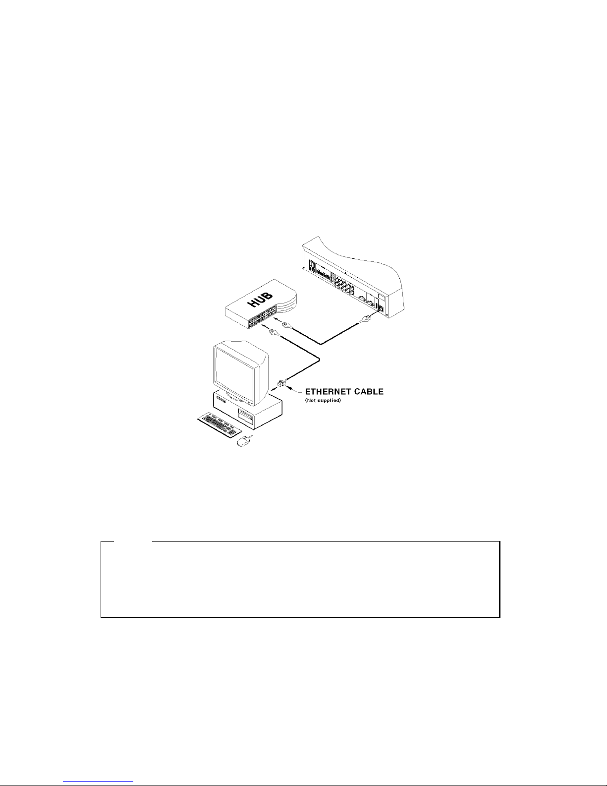
11.1. Connecting Ethernet
(1) Turn off power switch of MD800M
(2) Connect MD800M to hub with Ethernet cable
(3) Turn on power switch of MD800M
<ote>
1. Supply power to MD800M after connecting Ethernet cable to protect against electrical damage to
MD800M.
2. Check cable connection status.
3. Check LED on rear panel of MD800M after supplying power.
Page 42
42
11.2. Configuring etwork infomraiton of MD800M
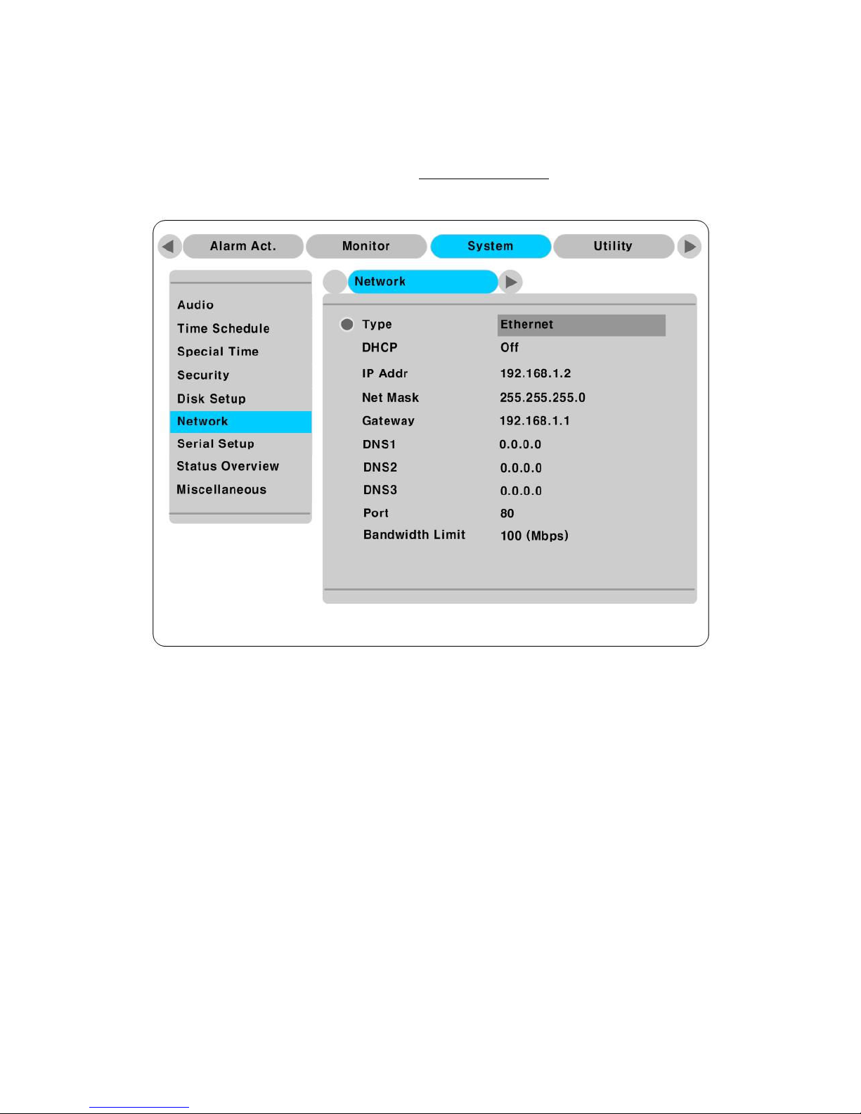
The following description is based on Ethernet connection. For more detailed information on the Network
setting page and way of using xDSL, please refer “eDVR USERS’ GUIDE
”.
(1) Press [MENU] button
(2) Select “System” using the [◀/▶] buttons and press the [▷] button.
(3) Select “Network” using the [▲/▼] buttons and press the [▷] button.
(4) Select “IP Addr” using the [▲/▼] and press the [▷] button.
(5) Press [EXIT] button after entering IP address in the dialogue box.
(6) Select “Net Mask” using the [▲/▼] buttons and press the [▷] button.
(7) Press [EXIT] button after entering Net Mask in the dialogue box.
(8) Select “Gateway” using the[▲/▼] and press the [▷] button.
(9) Press [EXIT] button after entering Gateway in the dialogue box.
(10) Select “DNS” using the [▲/▼] buttons and press [▷] button.
(11) Press [EXIT] button after entering DNS in the dialogue box.
(12) Press [EXIT] button to exit to montor mode
Page 43
43
12. Using Control Center Lite
Control Center List is a DVR Management Software and it makes DVR installtion & setting more easier
throguth a PC which is connected with DVR in Network. All configuration could be handled in OSD
menu of DVR without a PC, however, Control Center Lite makes the complete setting more simply.
12.1. Starting
To do setting DVR through Control Center Lite, PC and DVR should be connected via Network and installed
Contorl Center Lite on the PC.
12.1.1. PC system requirements for running Control Center Lite
Mininum Requirements Recommended Requirements
CPU Intel Pentium4 3Ghz(Hyper-Thread) Intel Core™ 2 Duo Processor
Memory 512MB 2GB
Video Card 128MB 128MB
Resolution
1280ⅹ1024 1280ⅹ1024
HDD recording
space
1GB or higher 1GB or higher
OS Windows XP SP2 Windows XP SP2
Etc. DirectX 8.1 or higher DirectX 8.1 or higher
12.2. Installing Control Center Lite
1> Execute “1.x.x.x Setup.exe” file in Set up CD.
To install Control Center Lite, user level of the PC should be Administrator mode.
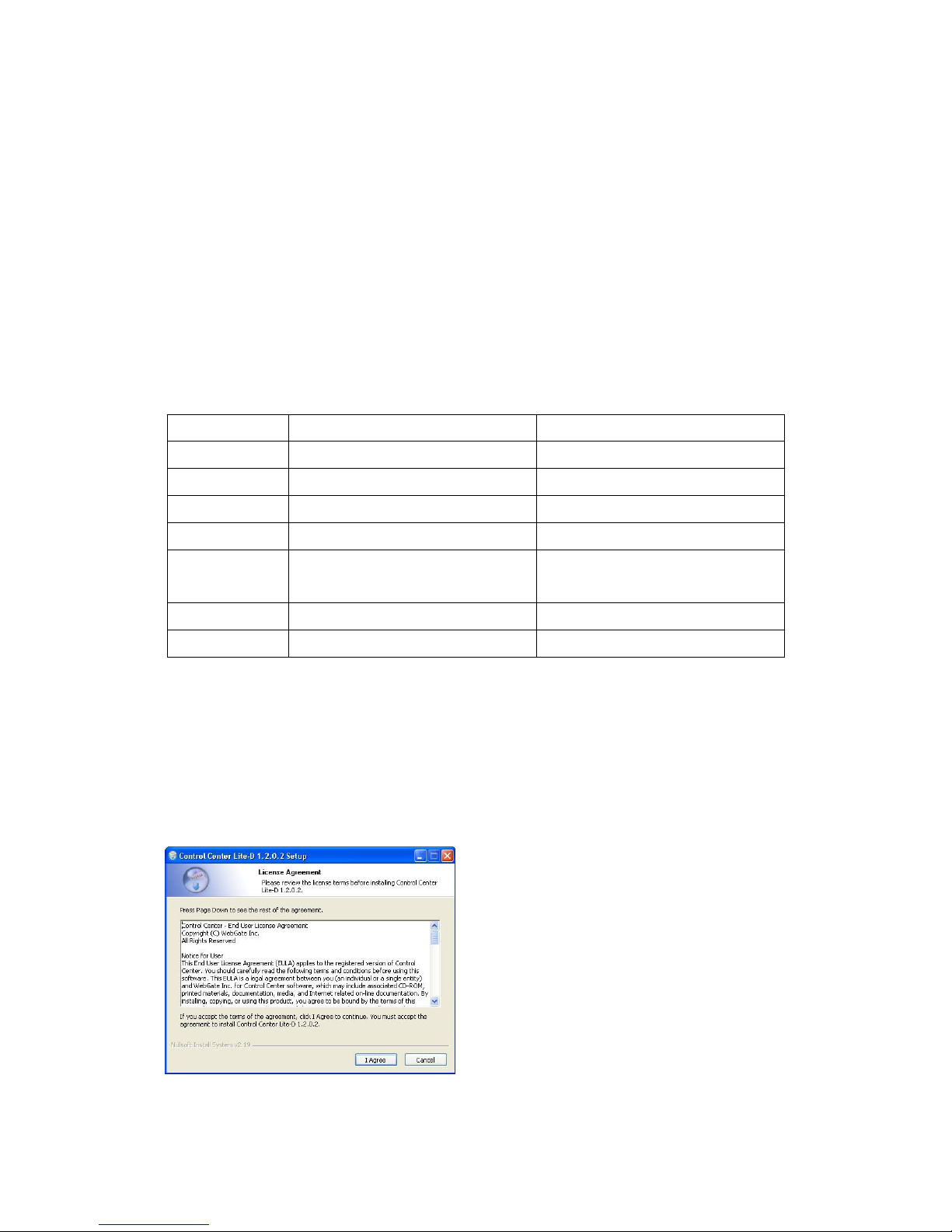
2> Click “I Agree” button to accept the license agreement
Page 44
44
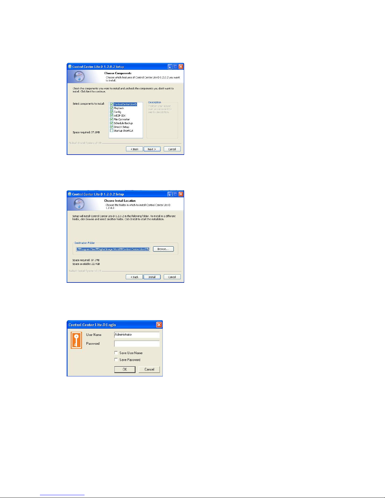
3> Select components which wish to install and press “Next” button.
“WESP SDK” must be installed.
4>.Click the “Install” button after selecting a directory to be insatalled.
12.3. Log-In
Enter User Name, Password and press “Ok” button.
The factory default value : User Name:Administrator, Password:admin
Page 45
45
12.4. Configuration Tool
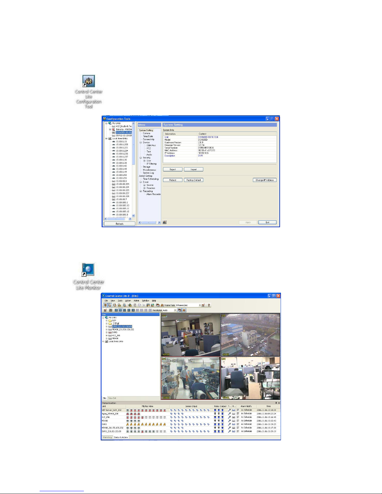
Click the icon on the desk top to run “Control Center Lite Configuration Tool”.
12.5. Monitor
* Max. 5 users could be connected simultaneously in one unit of MD800M.
Click the icon on the desk top to run “Control Center Lite Monitor”.
Page 46
46
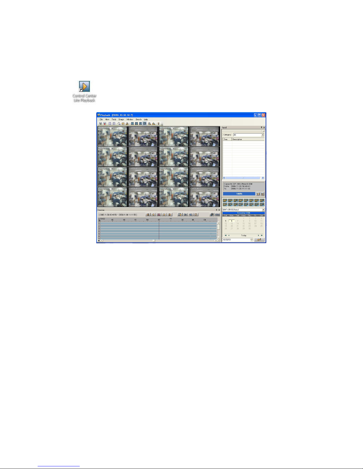
12.6. Playback
* Max. 2 user could be connected for playback in one unit of MD800M.
Click the icon on the desk top to run “Control Center Lite Playback”.
Page 47

47
APPENDIX
APPEDIX
APPEDIX
Page 48
48
#1. HDD
#1.1. Fundamental notions & terms
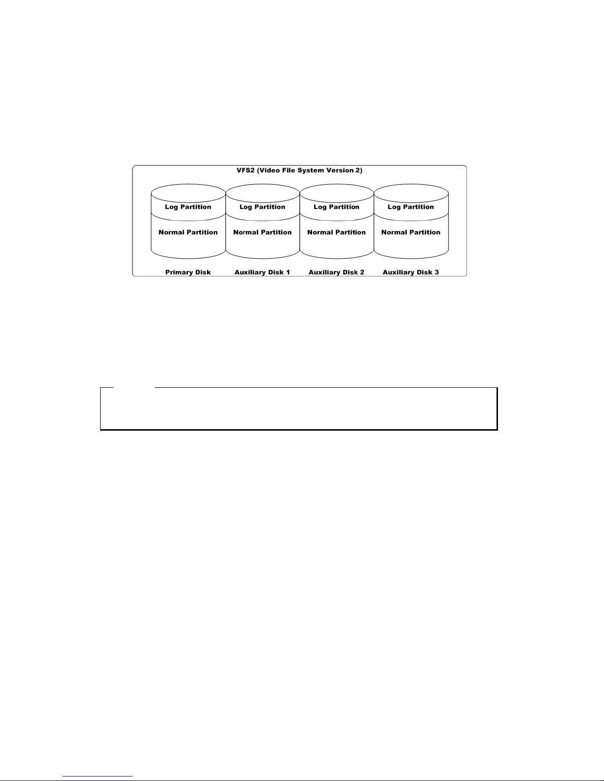
eDVR storing constructure (VFS2)
eDVR series has a peculiar storing constructure, and its features are as follows.
(1) It is possible to connect 2 sets of HDD internally (Internal, ATA Interface) and 63 sets of HDD
externally (External, 1 port of eSATA).
(2) All of the connected HDDs are recognized as one virtual disk, and eDVR supports upto 8TB.
<ote>
Log Partition To store the information of recorded data
Normal Partition To store the data as normal recording schedule
Backup
(1) Backup is possible only through 1 eSATA and HDD for backup should be formatted in FAT32 type.
(Its type is indicated as [F] in Disk Manager.)
Disk Manager
(1) When HDD is added or deleted physically, Disk Manager runs automatically after rebooting. If not,
you can run “Disk Manager” manually with moving “MenuUtilityDisk Manager”.
Page 49
49
Page 50
50
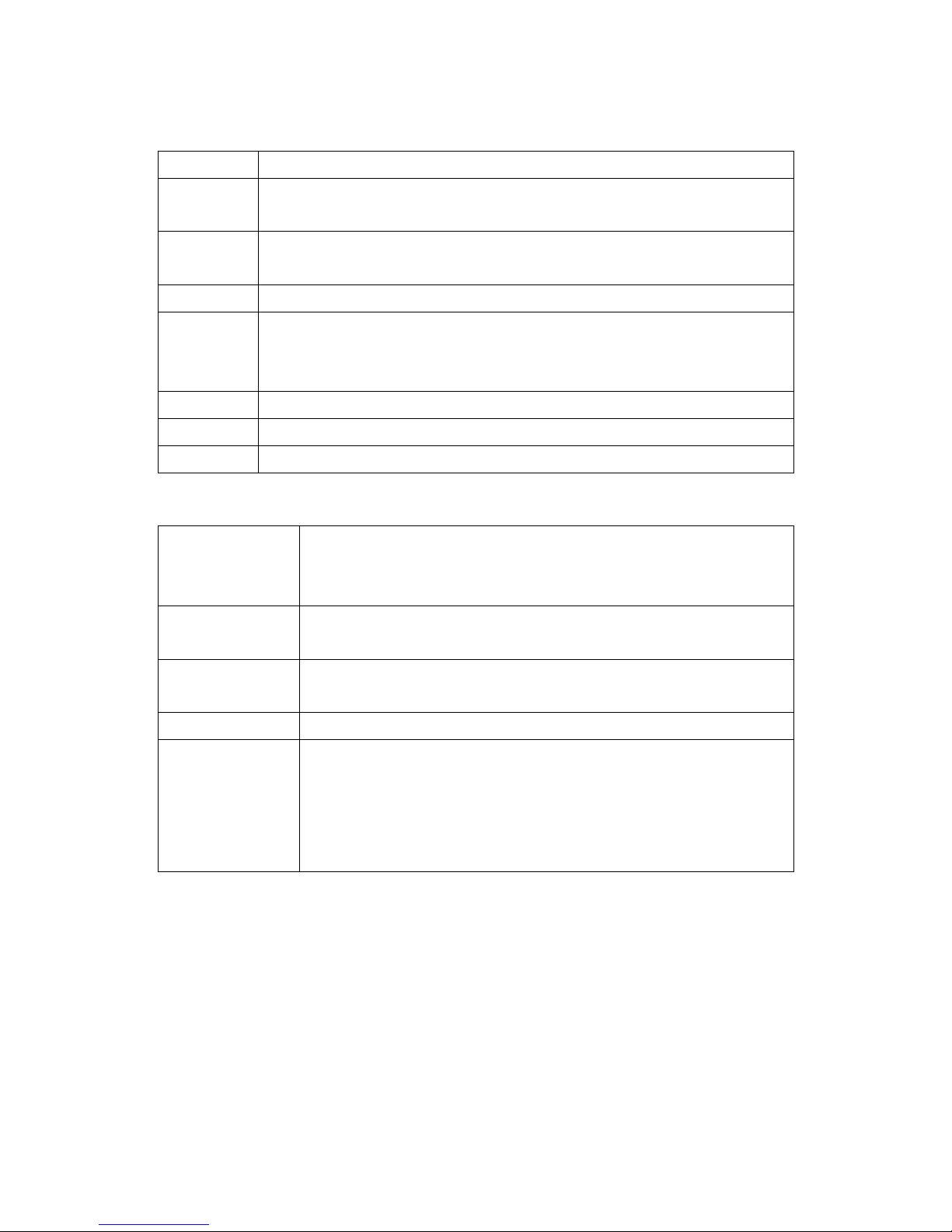
(2) HDD Type at Disk Manager
[R] Available recording status
[V] Connected and formatted as eDVR’s file system. If using ‘Add Used’ command, it will
be changed to [R]. There is no need to format.
[F] Connected but not available eDVR’s file system. After using ‘Add’, need to format for
making as [R]. Indicate FAT32 file system connected for backup.
[C] CD/DVD-Recorder
[X] HDD cable is not connected nor has some problem. In case of that, HDD should be
removed with using ‘Confirm Removed’ menu. In case of being [X] at the disk list, the
buzzer will ring until closing a disk manager.
IntA Internal Primary IDE Channel Master HDD
IntB Internal Secondary IDE Channel Master HDD
Ext External HDD, which can be reordered by the order of recognition
(3) HDD Managing Command
Add Add a HDD for recording. In case of adding a disk, “Alarm Partition” menu is
activated as an available status. “Alarm Partition” means that one HDD divides a
partion as Normal Recording & Alarm Recording part.
Add Used Add a HDD that has been used and formatted. There is no need to reformat. It is
possble only when HDD is added as Primary Disk.
Remove Remove current HDD. HDD can be reused without data loss by the ‘Add Used’
command.
Confirm Removed Use when a removed HDD is still listed. ALL DATA WILL BE LOST!
FAT32 Format : Use when connect to the external HDD
Format the partition of below 250GB to copy/backup by FAT32 file system.
It is necessary to create partition by using Disk manager on PC for this work.
In case the size is over 250GB, format each partition by FAT32 file system after
creating multiple partitions smaller than 250GB.
Page 51

51
#1.2. Installing HDD
Compatible HDD
It is recommended to use the following HDD models with the MD800M. If a non-recommended HDD is
used, WEBGATE Inc. will not guarantee the warranty.
Installation and extension of internal HDD-RACK HDD
In case of installation/adding or exchange HDD, follow the procedure as followings
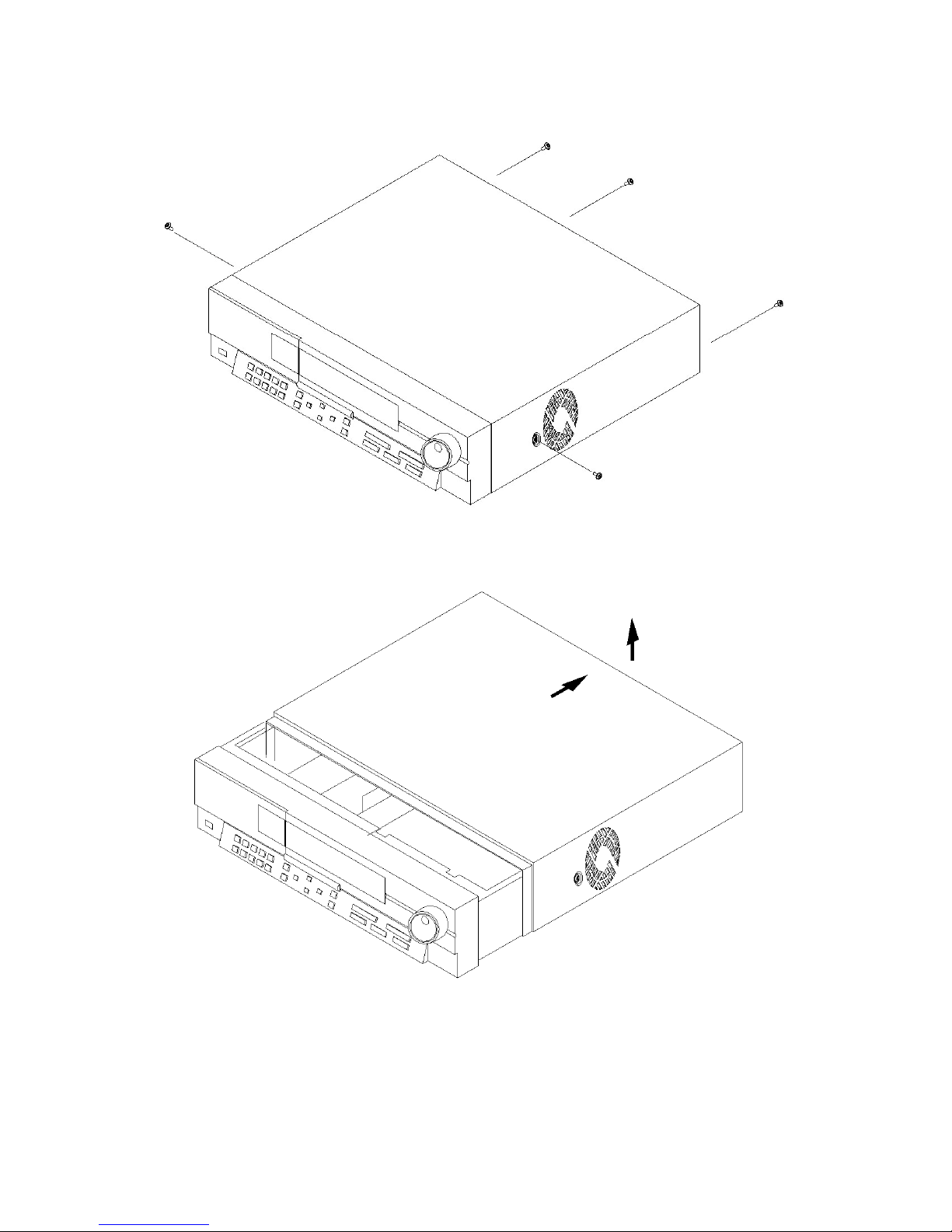
(1) Cut off the power to eDVR.
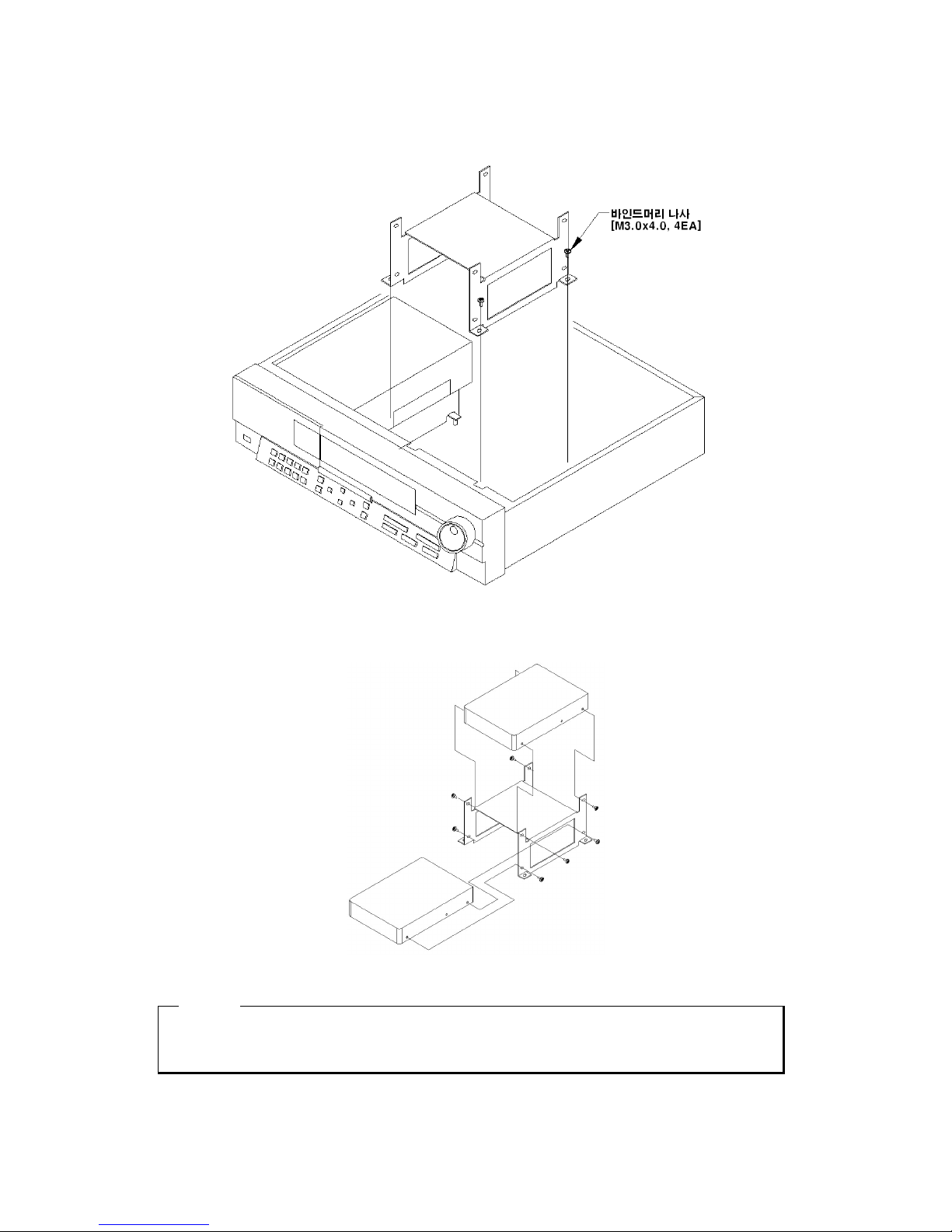
(2) Remove the 6 screws as illustrated below and pull up the cover from the rear part to open.
Page 52
52
Page 53
53
(3) Remove 4 HDD Bracket screws to take out HDD BRACKET.
(4) Fix the HDD into HDD Bracket with provided screws. Assemble an earth cable with HDD.
<<<<ote>>>>
When assembling a HDD, the back side of HDD should be with HDD BRACKET shown as above
figure.
Page 54
54
(5) Fix the assembled HDD and earth cable into case with screws.
(6) Assemble the top cover.
<ote> Caution for HDD Management
1. Replacing ‘SLAVE’ HDD of internal 2 HDDs causes permanent data loss in the SLAVE HDD.
2. MASTER HDD has all the index of stored data including ‘SLAVE’ HDD. Corruption on
‘MASTER’ HDD may cause total data loss. Be careful when handling the main HDD.
3. It is strongly recommended that all data within HDDs should be backed up before replacing a
‘MASTER’ HDD.
When installing one primary disk
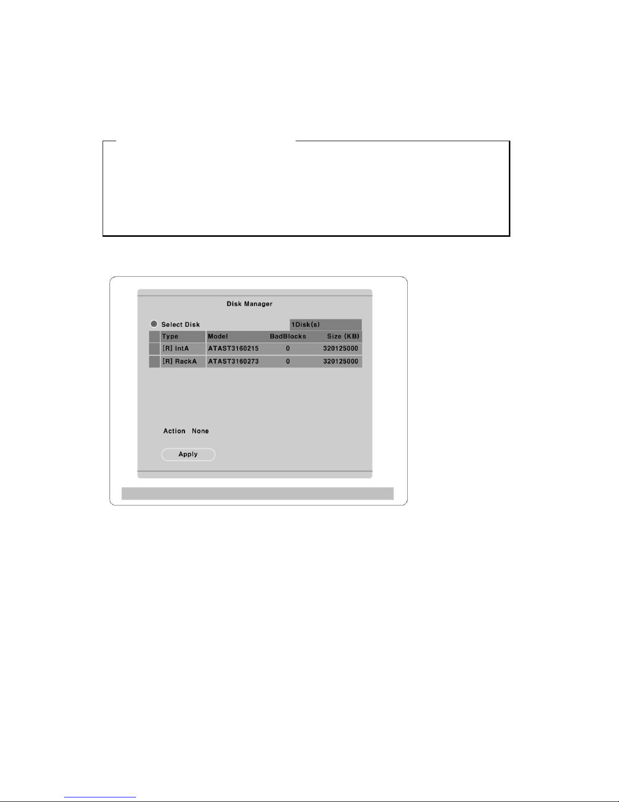
(1) When power is supplied to MD800M, “Disk Manager” runs automatically after rebooting. If not, run
it manually in “MenuUtilityDisk Manager”.
(2) There is a HDD that is indicated as “[F] IntA”. Select it.
(3) Select “Action” as “Add” and configure a size of alarm partition, and press “Apply” button. Then [F]
is changed to [R].
(4) Press the [EXIT] button to shut down “Disk Manager”. (If recording schedule is set, MD800M will
start recording.)
Page 55
55
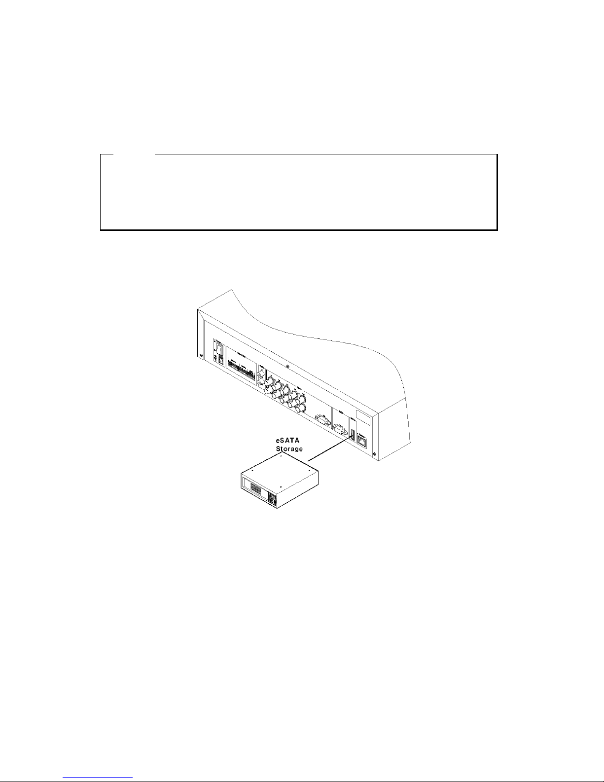
Expending External HDD (When using internal HDD as primary disk)
MD800M use eSATA as external storage device interface, and has one port to support it. Using this port,
maximum 8TB storage is installable.
<ote>
1. Some eSATA ports may not be recognized by the MD800M. Before purchasing, consult the local
WEBGATE distributor.
2. External storage should use external power.
3. For connection and setup of eSATA, please refer to the manual of related device.
Connect eSATA Interface cable as follows.
Page 56
56
When using Disk Farm
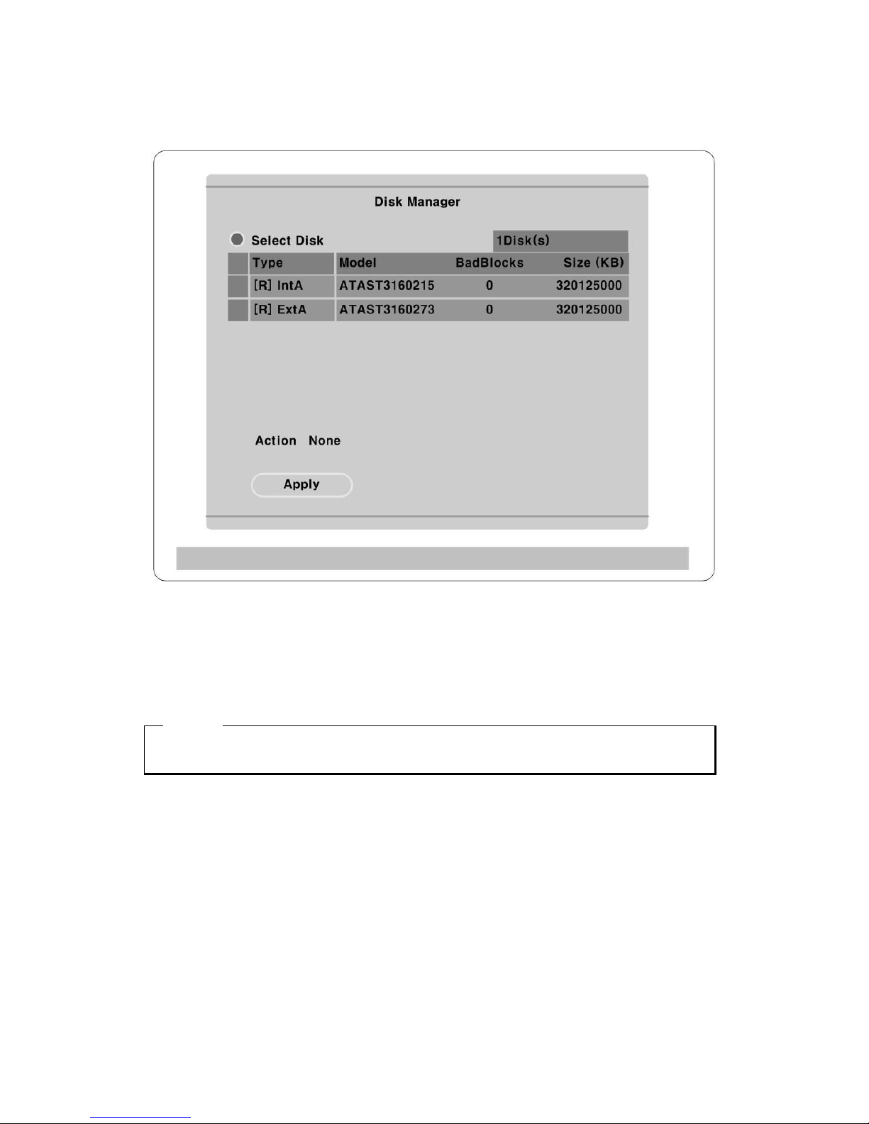
The following description is when MD800M has internal primary disk and 1 sets of eSATA HDD.
(1) When external HDD farm is connected to eSATA port, “Disk Manager” runs automatically. If not,
run it manually in “MenuUtilityDisk Manager”.
(2) Select a second HDD of [F] Ext. Press the “Apply” button after selecting action as “Add”. Then [F]
is changed to [R].
<ote>
If connecting the device that is used in MD800M, type will be indicated as [V].
(3) Press the [EXIT] button to shut down “Disk Manager”.
Page 57
57
When using RAID
The following description is when MD800M has internal primary disk and 1 set of IEEE1394 RAID.
<ote RAID>
Even though several HDDs are connected to RAID, MD800M will recognize them as only one HDD.
For connection and setup of RAID, please refer to the manual of related device.
(1) When external HDD RAID is connected to eSATA port, “Disk Manager” runs automatically. If not,
run it manually in “MenuUtilityDisk Manager”.
(2) Select a second HDD of [F] Ext and configure a size of alarm partition. Press the “Apply” button
after selecting action as “Add”. Then [F] is changed to [R].
<ote>
If connecting the device that is used in MD800M, type will be indicated as [V].
(3) Press the [EXIT] button to shut down “Disk Manager”.
Page 58

58
Replacing HDD
Checking HDD
MD800M file system (VFS2) sensors bad sector automatically, and the sensored bad sector is not used.
The following means when HDD is broken or has some problem in connection.
(1) When playback is stopped or MD800M is rebooted in specific playback range or image searching per
event is impossible.
(2) When recording is stopped and “Disk Manager” shows HDD type as [X].
When disk is broken
In case of not reading or writing a disk comes from physical error or occuring a bad sector at the
beginning of a disk, it is decided as a disk error.
In case of being other disk inside eDVR or able to storage a data, it is recorded at the next disk.
Simultaneously, it notifies bad disk marked as [X] to a user popping up eDVR disk manager.
Keeping Data
To keep the stored data by the fixed time or semi permanently, you should back up or reserve as HDD
itself.
Backup
(1) Connect backup HDD to IEEE1394 port.
(2) Go to playback mode with pressing the [Playback] button.
(3) Press the [SELECT] button and then [MENU] button.
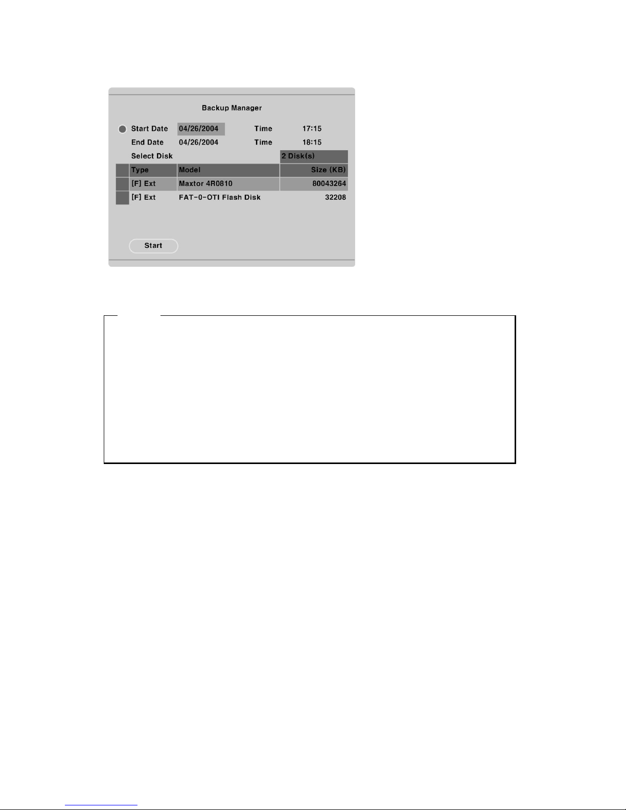
(4) Run “Backup Manager” with selecting the “Backup Data” menu.
Page 59
59
(5) Set backup range and press the “Start” button after selecting backup HDD.
<ote>
1. Backup HDD should be formatted as FAT32 type.
2. Backup data can be replayed with specific S/W in PC such as Control Center Lite-D or MiniPlayer.
3. Backup data is made as “*.re4” file and recognized as CD-R 700MB / DVD-R 4G per each file.
4. Support CD-R backup and should be over CD-R 700MB / DVD-R 4G media.
5. In course of backup, “Auto Delete” function doesn’t run. If HDD is full, recording may be stopped
instantly.
6. For more detailed information of Control Center Lite-D’s backup, please refer to the “eDVR User’s
Guide”.
Page 60

60
Caution in using HDD
For handling or guaranteeing HDD, WEBGATE follows HDD guaranty condition. WEBGATE doesn’t
bear the responsibility about data loss by user’s mistake in operating.
<ote>
It supports only DVD backup. CD backup will be supported later.
For the details, please contact to local distributor.
Page 61

61
#2. Using CD-ROM
Components of CD- ROM disc
Installation Guide : eDVR MD800M Installation Guide
User’s Guide : eDVR MD800M User’s Guide
Control Center Lite-D
: Control Center Lite-D User’s Guide
(Control Center lite-D Remote Management
Program)
Acrobat Reader : Version 7.0
Preparation
To read manual of CD-ROM disc, Adobe Acrobat 7.0 should be installed in client’s PC.
<ote>
If Adobe Acrobat Reader is not installed within client’s PC, use the Acrobat Reader program of CD-
ROM.
Reading manual of CD-ROM
Follow the steps to read User’s Guide.
(1) Insert the supplied CD-ROM into CD-ROM drive of PC.
(2) Open the User’s Guide with PDF file.
Page 62
62
#3. How to recognize manufacturing date
The manufacturing date by Webgate can be recognized by S/N(Serial Number) attached at the each
product.
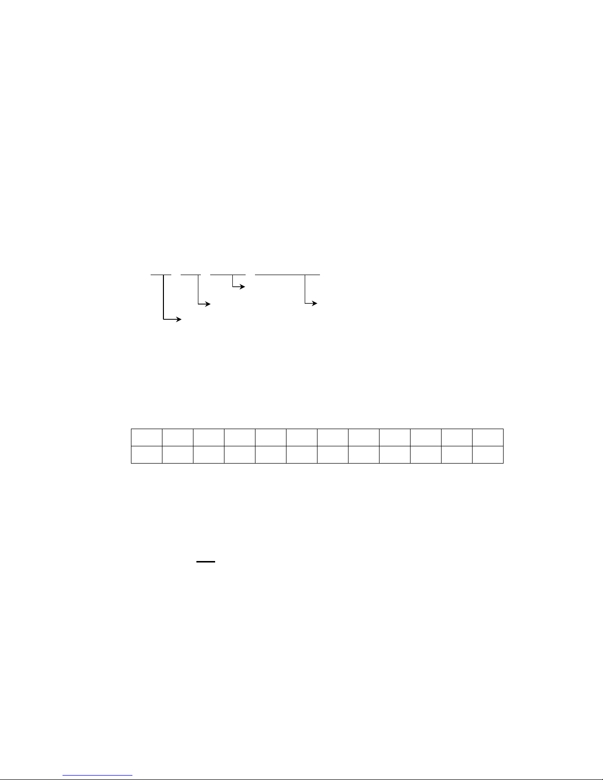
S/ : Serial umber
Management number for each Webgate product to combine twelve alphabet character and digit including
model name, manufacturing year/month/week
You can see serial number by looking at the bottom of product attached label and system info of
Configuration Tool.
Serial umber Format
□ □
□ □ □ □ □ □ □ □ □ □
Year/Month
Webgate No. Webgate No.
Model Name No.
(1) 1~2 digits : Identify Model name of product
(2) 3~8, 8~12 digits : Webgate internal number
(3) 5~6 digits : Manufacturing year
(4) 7 digits: Manufacturing month
Please see the below table for manufacturing month.
Jan Feb
Mar Apr May Jun Jul Aug Sep Oct Nov Dec
1 2 3 4 5 6 7 8 9 A B C
The example of verifying manufacturing date using serial number
The below S/N can be verified as following as:
『
『『
『 D60507B22051 』』』』
(1) “D6” means “MD800M” product
(2) “07B” means that it was manufactured on November of 2007
Page 63

63
#4. Specification
General
CPU
32bit RISC Processor
Flash memory
32MB
Main memory
128MB
OS
Embedded LINUX
Video channel
8Ch. analog video inputs via BNC connector
NTSC or PAL video format are supported (Auto detect)
Storage device
Int.: 2 HDD bays including
Ext: 1 eSATA connection ports
Supports Disk management tool for all disks.
Total manageable capacity: 8 TB
Intelligent file system
Data-loss protection against power failure
* under development
Image compression and Recording
Technology
MPEG-4, JPEG(Remote monitoring only)
Image quality level
5 Level (Q1 ~ Q5)
Recording speed
Max. 240ips(NTSC) / 200ips(PAL) @ Half D1 Resolution
monitor (Playback speed)
Total 60ips(NTSC)/50ips(PAL)
(Performance)
1/4/9ch
1x, 2x, 4x, 8x, 16x, 32x, 64x (Forward/Reverse playback)
Resolution
CIF : 352 x 240 / 352 x 288
Half D1 : 704 x 240 / 704 x 288
D1 : 704 x 480 / 704 x 576
Motion Detection Grid
22x15(NTSC)/22x18(PAL)
Playback search
Instant Playback by time and event
Step-forward, Step-reverse playback
Alarm trigger
Motion detection, Sensor input or Text input
Alarm log record
Log search
Log monitoring via OSD & Network
Pre/Post alarm
Pre : 0~5 seconds
Post : 0~60 seconds
Page 64

64
Schedule recording
Daily : Day / Night / Four-segment time frame
Weekly : Weekdays / Weekends, Exception days
Conditions : Normal / Event
Text Data recording
POS/ATM transaction information archived along with
corresponding video data
Manual recording
Manual(Emergency) record triggered by font key
Audio Recording & Playback
Recording level
-7~8 (16 step) recording level
Monitoring
Support remote monitoring and two way audio
etwork
Program
Control Center Lite-D (Bundle)
Support Control Center series CMS S/W and WESP SDK
Protocol
TCP/IP, ARP, ICMP, DHCP, PPPoE
Connection
10/100Mbps Ethernet (RJ-45)
S/W upgrade
Firmware upgrade via Network and USB
Simultaneous users
Monitoring : Max. 5 users
Playback : Max. 2 users
Security
Password (User or Administrator authentication)
Monitor Output
Monitor
Max. 480 field/sec
1ch, 4ch, 9ch, Auto & User Defined Sequence
2 CVBS and 1 VGA output
True color OSD
Alarm Pup-up
Triggered by recording event
Digital zoom
2x (Live mode)
Environment
Operation temperature
5 ~ 45℃
Storage temperature
-10 ~ 55℃
Operation humidity
30~80%, free of condensation
Storage humidity
93% below, free of condensation
Page 65

65
Data Backup/Expansion/Copy
Data backup
External HDD(eSATA)
Internal CD-R/DVD-R
Backup reminder
5~ 95% alarm
AVI Copy
External USB memory disk(USB 1.1 compatible) on USB port
Input/Output
Video Output
2 CVBS main monitor
1 VGA
Audio
1 Input : Line-in, 1 Vpp
1 Output : Line-out, 1Vpp
Buzzer
Software-controlled 1 internal buzzer
Digital output
Software-controlled 4 relay outputs(Max 125VAC/60VDC)
Digital output schedule
Daily : Day / Night / Four-segment time frame
Weekly : Weekdays / Weekends
Conditions : MD, Sensor, Text inputs
Sensor input
Software-controlled 8 sensor inputs (Support dry contact)
Serial port
RS232(1),RS485(2)
PTZ control
Control method (local)
Front panel button & IR remote controller
Control method (remote)
On-the-screen PTZ control on PC
Return home position support
Preset mode
16 points preset per channel
16 auxiliary function
Electricity
Power (applied adaptor)
12V DC 10A
Power consumption
Max. 85W
Typical 60W
Page 66
66
Mechanical
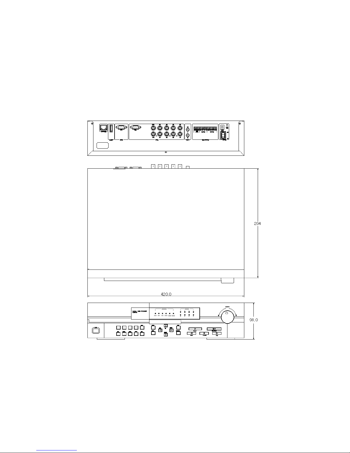
Dimension (WⅹⅹⅹⅹDⅹⅹⅹⅹH)
420.0 x 294.0 x 98.0
Weight
5.5 kg (with one HDD)
Page 67

67
WEBGATE Inc.
6F, Hanlim Venture Town Bldg., 689-6, Geumjeong-dong, Gunpo-si,
Gyeonggi-do, Korea (435-862)
Tel : (82-31) 428-9300
Fax : (82-31) 455-3955
www.webgateinc.com
The contents of this manual can be modified in accordance with Firmware or Software upgrade. In the
interest of continually improving products, approval & outlook can be modified without prior notice
 Loading...