

Page 1

i-Rec B104
Installation Guide
(v 1.4)
Page 2

FCC Compliance Statement
Caution
approved by the party responsible for compliance could void the user's authority to operate the
equipment.
NOTE:
digital device, pursuant to part 15 of the FCC Rules. These limits are designed to provide
reasonable protection against harmful interference in a residential installation. This equipment
generate, uses and can radiate radio frequency energy and, if not installed and used in
accordance with the instructions, may cause harmful interference to radio communications.
However, there is no guarantee that interference will not occur in a particular installation. If this
equipment does cause harmful interference to radio or television reception, which can be
determined by turning the equipment off and on, the user is encouraged to try to correct the
interference by one or more of the following measures:
- Reorient or relocate the receiving antenna.
- Increase the separation between the equipment and receiver.
- Connect the equipment into an outlet on a circuit different from that to which the receiver is
connected.
- Consult the dealer or an experienced radio/TV technician for help.
: Any changes or modifications in construction of this device which are not expressly
This equipment has been tested and found to comply with the limits for a Class B
CAUTION
Danger of explosion if battery is incorrectly replaced.
Replace only with the same or equivalent type.
Dispose of used batteries properly with regards to environmental considerations.
2
2003. 06. 30 (v 1.4)
WEBGATE Inc.
Page 3

Important Notice
1. When i-Rec B104 is in operation, do not place heavy monitors or other items on top of unit.
Do not vertically stack more than four i-Rec B104s.
2. i-Rec B104 is not weatherproof. Therefore consider environmental specifications that are
included in the manual. In case of outdoor use, equip weatherproof case to protect i-Rec
B104 from water, moisture, or severe temperature variations (higher or lower than
specifications). Clean i-Rec B104 by gently wiping outside shell with a clean, dry cloth.
3. Be sure to use the DC adapter that is provided with the unit. Connecting i-Rec B104 directly
to an AC current may cause electrical damage to i-Rec B104.
4. Be cautious of handling i-Rec B104. Physical shocks may harm the product.
5. i-Rec B104 is made with a metal case. When installing the camera, be sure it is attached
securely to avoid any injuries. Be careful to locate the camera where children cannot reach
it.
6. If i-Rec B104 does not operate properly, please contact your WebGate distributor for after
sales service. In all cases, you are prohibited to disassemble the product. If so, WebGate is
not responsible for any malfunction and will void service warranty.
7. Security surveillance laws may differ for each country and from region to region. Therefore,
please contact the local authorities first to avoid any surveillance law violations and use for
authorized purposes only.
WEBGATE Inc.
2003. 06. 30 (v 1.4)
3
Page 4

i-Rec B104 Contents
Contents
Introduction............................................................................................................................... 6
1. Key Features.................................................................................................................... 6
2. Supplied Accessories....................................................................................................... 7
3. Product Views and Description ........................................................................................ 9
Installing & Connecting.......................................................................................................... 10
4. Installing i-Rec B104 ...................................................................................................... 10
4.1. Connecting cameras to i-Rec B104......................................................................... 10
4.2. Connecting i-Rec B104 to Network ..........................................................................11
4.2.1. Connecting i-Rec B104 to PC directly...............................................................11
4.2.2. Connecting i-Rec B104 to Local Network......................................................... 12
5. Setting i-Rec B104 & Getting an Image.......................................................................... 13
5.1. Installing CamViewer II .......................................................................................... 13
5.1.1. Installation of Software..................................................................................... 13
5.1.2. Uninstalling ...................................................................................................... 14
5.2. Connecting to i-Rec B104 ....................................................................................... 15
5.3. Setting IP address................................................................................................... 16
5.4. Setting Camera Input Channel................................................................................ 17
5.5 Checking Images of i-Rec B104.............................................................................. 18
6. Installing HDD ................................................................................................................ 20
6.1. Usable HDD............................................................................................................ 20
6.2. HDD Installation Procedure..................................................................................... 20
7. Recording & Playback.................................................................................................... 24
7.1 Setting HDD............................................................................................................ 24
7.2. Setting Time................................................................................................................ 25
7.3. Setting Recording Schedule ....................................................................................... 26
7.4. Playback..................................................................................................................... 28
8. Input / Output ................................................................................................................. 30
8.1. Connecting Serial Port................................................................................................ 31
8.1.1. Specifications of Serial Port ............................................................................. 31
8.1.2. Serial Port View ............................................................................................... 31
8.1.3. Connecting & setting RS-232 port.................................................................... 31
8.1.4. Connecting & setting RS-485 port.................................................................... 32
8.1.5. Connecting & setting RS-422 port.................................................................... 33
4
2003. 06. 30 (v 1.4)
WEBGATE Inc.
Page 5

Contents i-Rec B104
8.2. Connecting Alarm Output........................................................................................ 35
8.2.1. Specifications of Alarm Output ......................................................................... 35
8.2.2. Alarm output port view ..................................................................................... 35
8.2.3. Connecting & Setting ....................................................................................... 35
8.3. Connecting Sensor Input......................................................................................... 37
8.3.1. Specifications of Sensor Input.......................................................................... 37
8.3.2. Sensor Input Port View .................................................................................... 37
8.3.3. Connecting & Setting ....................................................................................... 37
8.3.4. Connecting sensors for 1.0 or below main version PCB of i-Rec B104............ 38
8.4. Connecting Impedance Setup Switch for Video Input ............................................. 39
8.5. Video Input.............................................................................................................. 39
APPENDIX .............................................................................................................................. 40
#1. Frequently Asked Question (FAQ) .............................................................................. 41
#1.1. About i-Rec B104’s Feature................................................................................. 41
#1.2. About i-Rec B104 Installing ................................................................................. 43
#2. Utilizing IP Addresses on Local Network..................................................................... 46
#2.1. Introduction.......................................................................................................... 46
#2.2. IP Construction and Network class...................................................................... 46
#2.3. C-class Network .................................................................................................. 47
#3. Setting the fixed IP address on PC............................................................................. 50
#4. CRS Help ................................................................................................................... 52
#4.1. When using ADSL ............................................................................................... 52
#4.2. When resetting local network from ADSL ............................................................ 55
#4.3. When using Cable modem .................................................................................. 58
#5. Upgrading i-Rec B104 Firmware ................................................................................ 59
#5.1. Connecting i-Rec B104 to PC.............................................................................. 59
#5.2. Upgrade firmware with upgrading program.......................................................... 59
#6. Using CD-ROM........................................................................................................... 61
#7. Specifications ............................................................................................................. 62
WEBGATE Inc.
2003. 06. 30 (v 1.4)
5
Page 6

i-Rec B104 Introduction
Introduction
1. Key Features
i-Rec B104 is a 4-channel box style Network DVR. It is an all-in-one system with a Web server
of embedded Linux, a networking device, and a HDD (Removable). i-Rec B104 only needs
designated power supply and network connection in order to operate.
Monitoring through Network
RS 232 / RS 485 / RS422 port support for PTZ control
Embedded Linux OS for excellent stability and less downtime
Wavelet compression (30%~300% greater efficiency than JPEG) for higher refresh rate and
crisper images
4 channels video input support
4 alarms output support
S/W motion detection
Dynamic IP (DHCP, Floating IP) support (xDSL and Cable modem)
6
2003. 06. 30 (v 1.4)
WEBGATE Inc.
Page 7
Introduction i-Rec B104
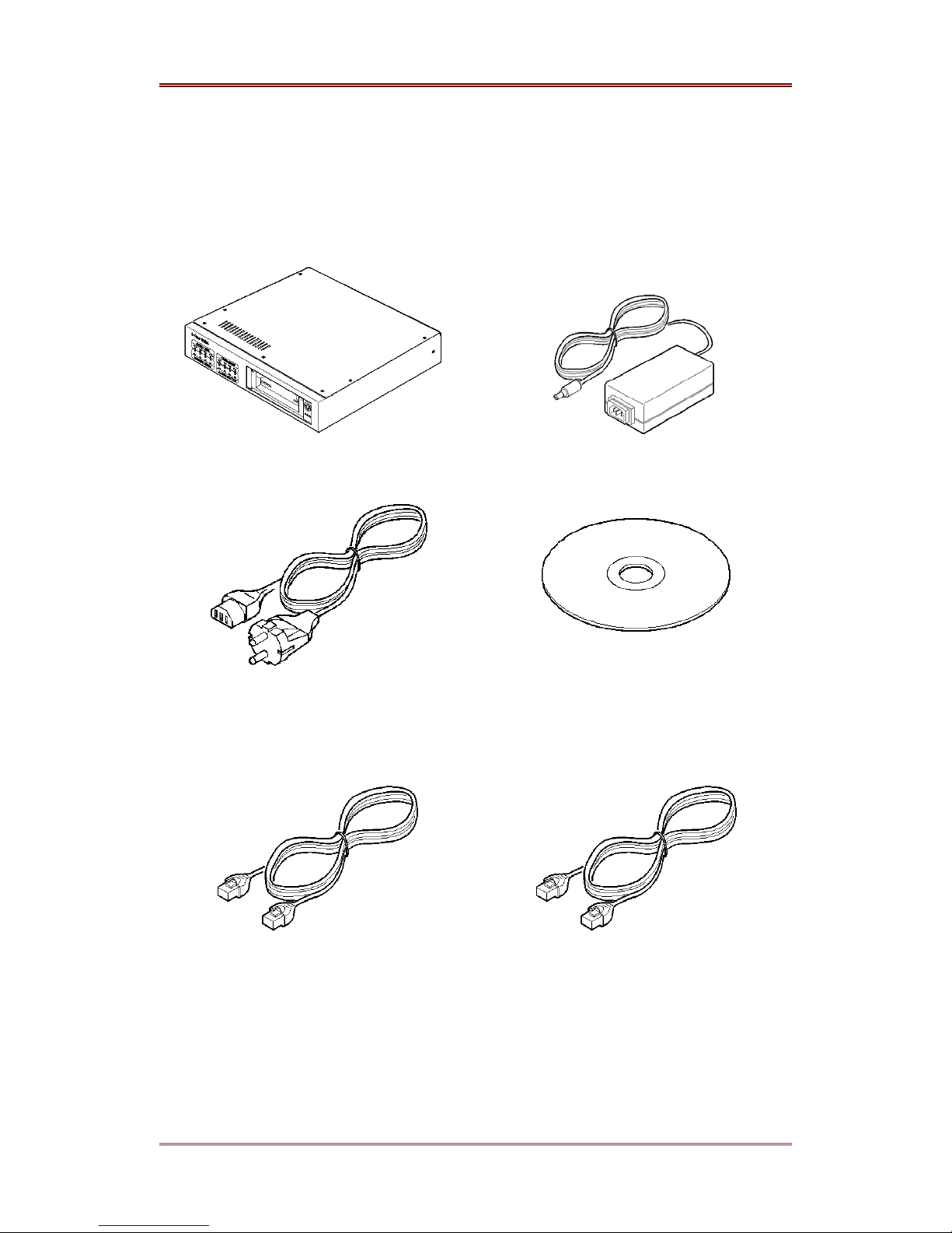
2. Supplied Accessories
Unpack and check all items.
1. i-Rec B104 (1)
2. DC POWER SUPPLY (1)
(110V ~ 220V)
3. AC POWER CORD (1)
5. ETHERNET CABLE (1, RED)
(UTP CATEGORY 5 CROSS CABLE)
4. CD-ROM (INCLUDING CAMVIEWER
AND OPERATING INSTRUCTIONS) (1)
6. ETHERNET CABLE (1, IVORY)
(UTP CATEGORY 5 DIRECT CABLE)
WEBGATE Inc.
2003. 06. 30 (v 1.4)
7
Page 8
i-Rec B104 Introduction
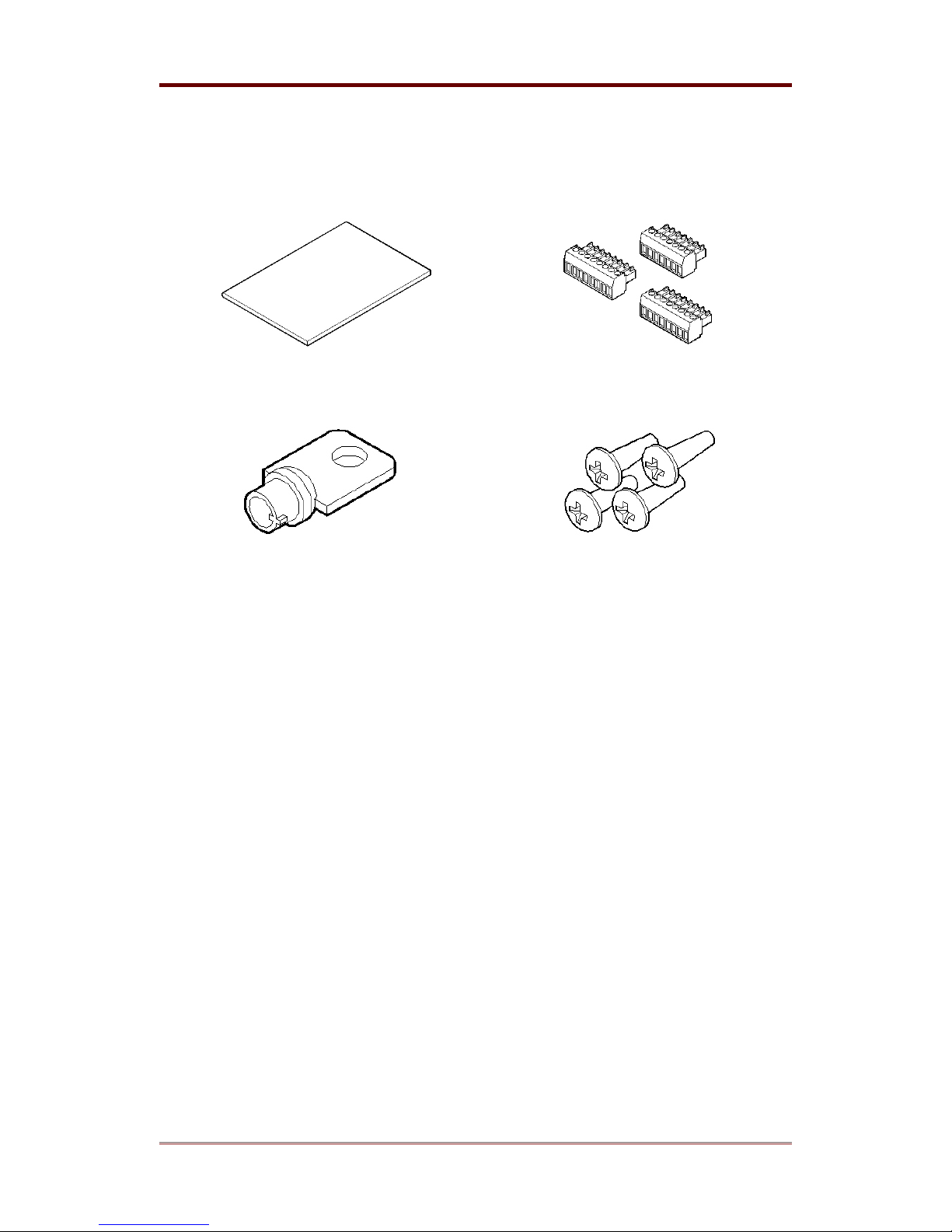
7. INSTALLATION GUIDE (1)
8. TERMINAL BLOCK (3)
(8PIN x 2, 7PIN x 1)
9. HDD MOBILE RACK KEY (1)
10. SCREW (4)
8
2003. 06. 30 (v 1.4)
WEBGATE Inc.
Page 9
Introduction i-Rec B104
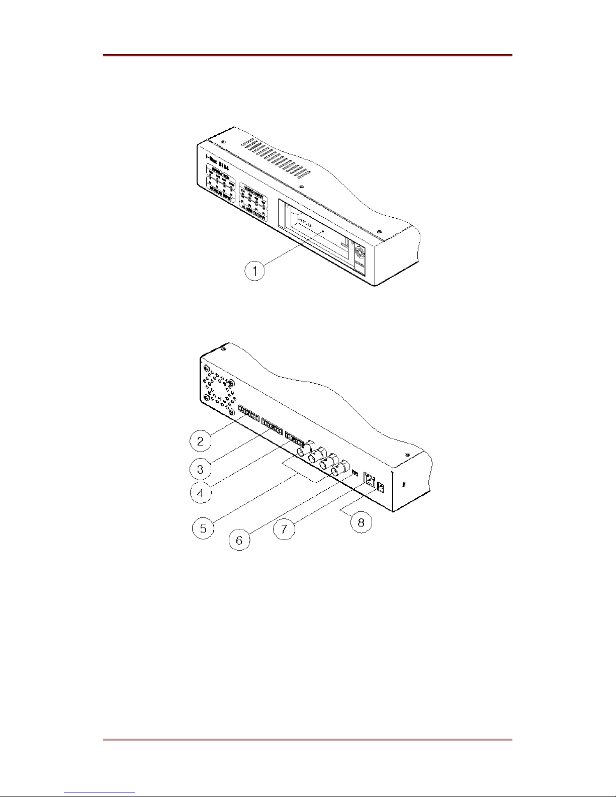
3. Product Views and Description
(1) HDD mobile rack
(2) Alarm output
(3) Sensor input
(4) Serial port
(5) Video input
(6) Impedance control switch
(7) Ethernet
(8) DC power
WEBGATE Inc.
2003. 06. 30 (v 1.4)
9
Page 10
i-Rec B104 Installing & Connecting
Installing & Connecting
4. Installing i-Rec B104
This user’s guide describes the most two common network conditions for installing B-104:
(1) i-Rec B104 and administrator’s PC uses fixed or private IP address.
(2) Computers and B104 are connected directly or to local network.
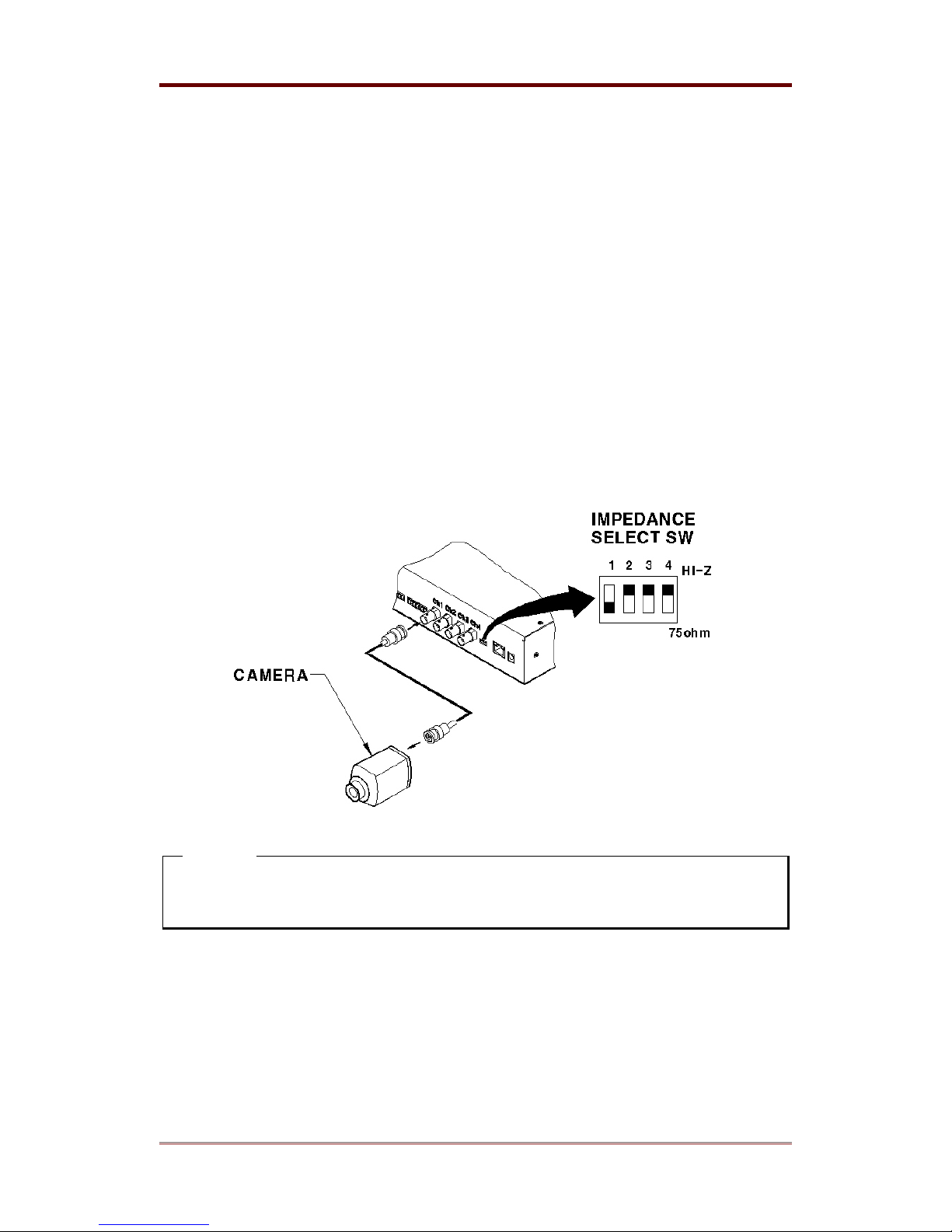
4.1. Connecting cameras to i-Rec B104
(1) Connect i-Rec B104 to camera(s) with BNC Cable.
(2) Set impedance control switch of the connected channel. Set impedance by moving switch
<Note>
For more exact settings, please refer to “Impedance setup switch for video Input” of “Input /
Output” in User’s Guide.
10
2003. 06. 30 (v 1.4)
WEBGATE Inc.
Page 11
Installing & Connecting i-Rec B104
4.2. Connecting i-Rec B104 to Network
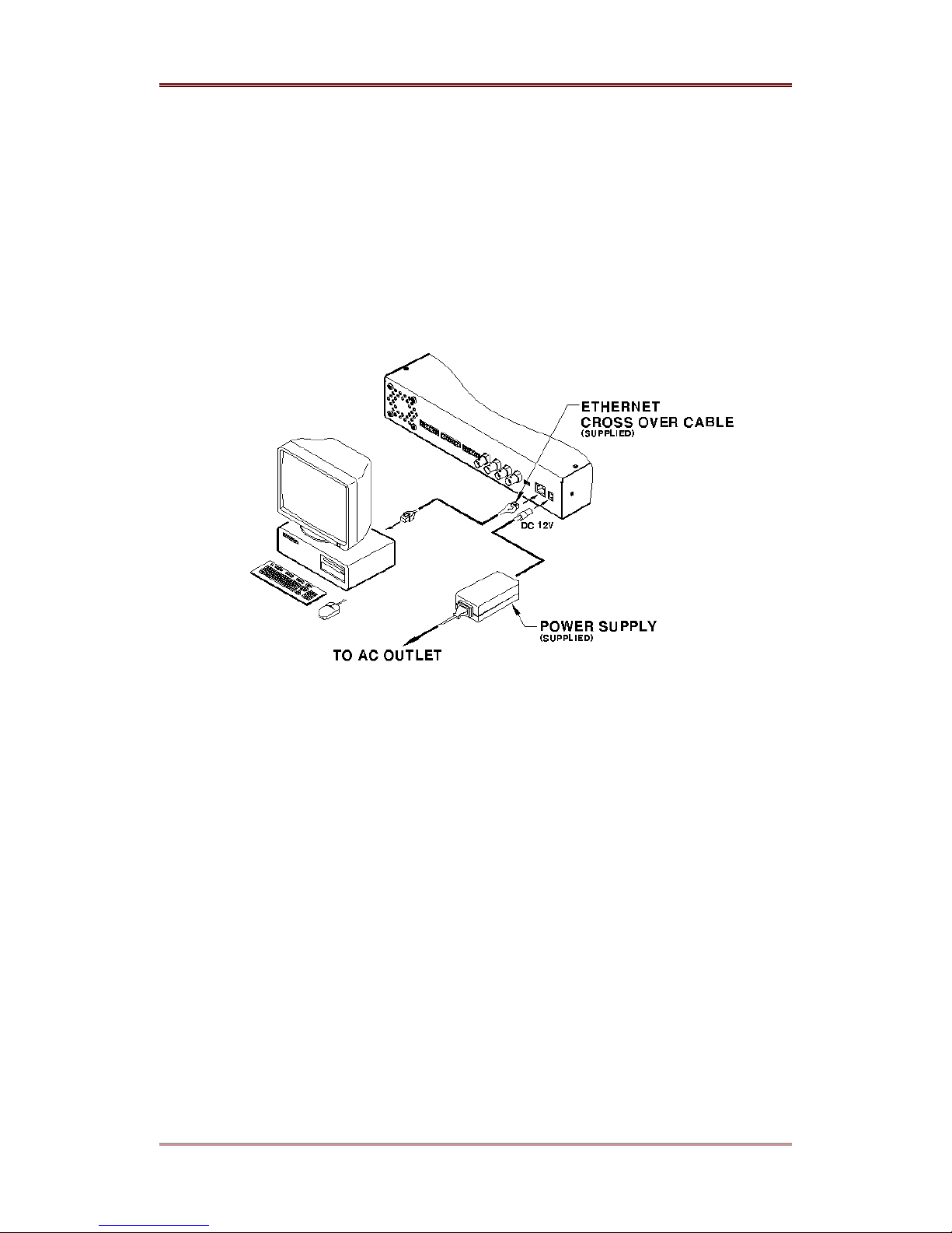
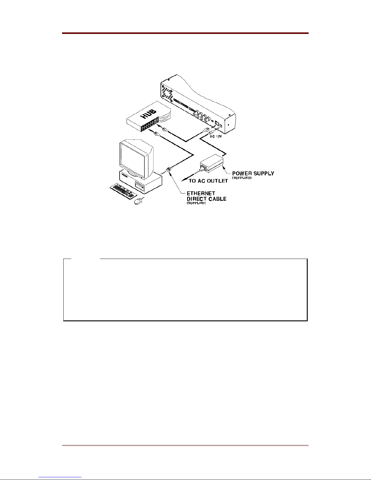
Connect i-Rec B104 to client’s PC directly with crossover cable or through HUB with direct cable.
Please refer to the following figures.
4.2.1. Connecting i-Rec B104 to PC directly
(1) Connect i-Rec B104 to client’s PC with crossover cable (Red Ethernet cable).
(2) After supplying power to AC adapter, connect DC12V connector to B104.
(3) If PC is set with dynamic IP, change it into suitable IP address on same network. For more
detailed information, please refer to “Appendix #3 Setting the fixed IP address on PC”.
WEBGATE Inc.
2003. 06. 30 (v 1.4)
11
Page 12
i-Rec B104 Installing & Connecting
4.2.2. Connecting i-Rec B104 to Local Network
(1) Connect B104 to HUB with direct cable (Ivory Ethernet cable).
(2) Connect the supplied AC adaptor to B104.
<Note>
1. To prevent damage to B104, connect power cable only after connecting Ethernet cable.
2. Ethernet cable should be pushed and connected, If not, noise may occur.
3. Check the LED of B104 after supplying power. After power is supplied, yellow LED is on
for the first 5-6 seconds and then goes off. Green LED is on for the first 1-2 seconds, and
then blinks once every second as long as the network is connected.
12
2003. 06. 30 (v 1.4)
WEBGATE Inc.
Page 13
Installing & Connecting i-Rec B104
5. Setting i-Rec B104 & Getting an Image
The following procedure is for installing i-Rec B104 and checking basic operation. For more
information, please refer to “
CamViewer II User Guide”.
5.1. Installing CamViewer II
5.1.1. Installation of Software
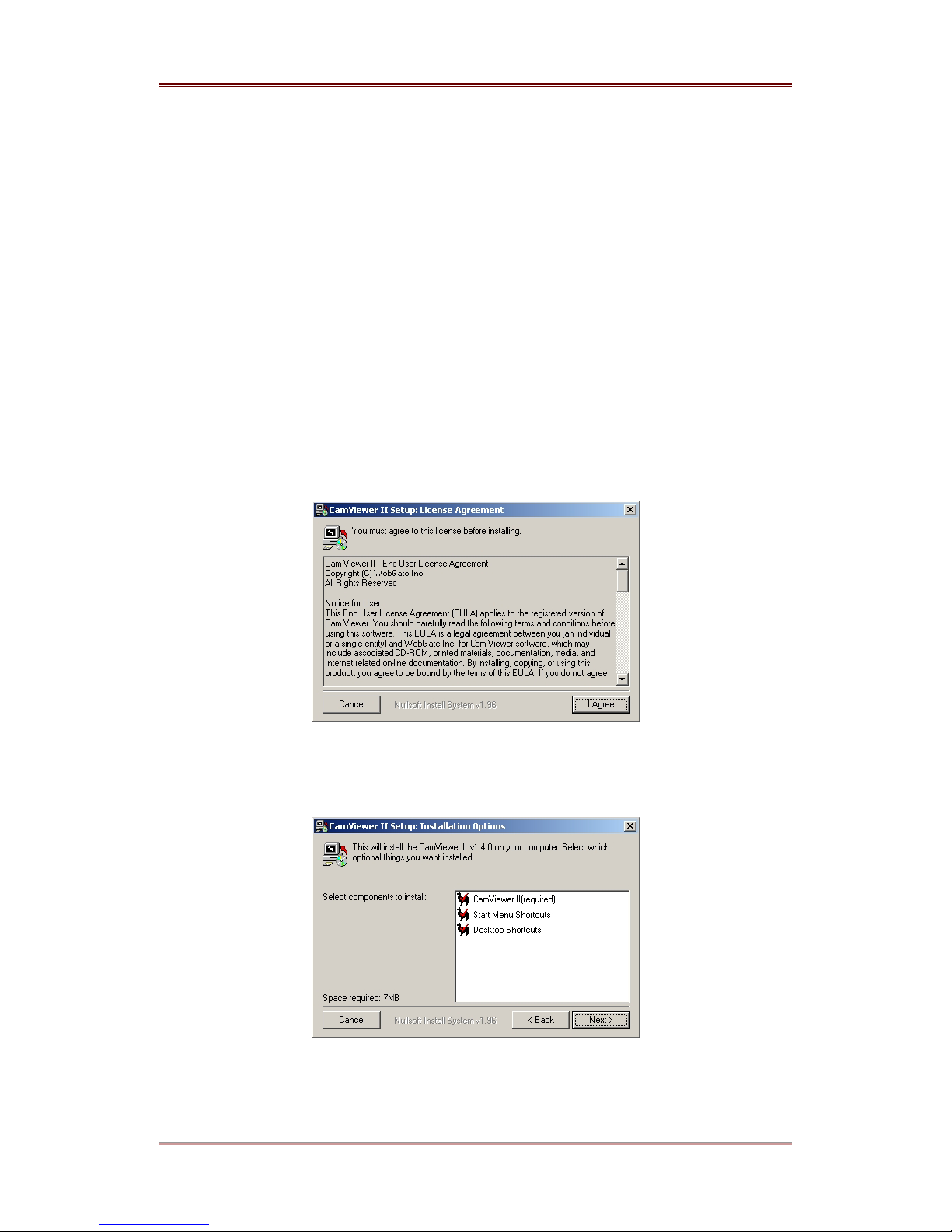
(1) Insert Setup CD-ROM into CD-ROM drive of administrator’s PC
(2) Copy the ‘CamViewer II x.x.x Setup.exe’ file onto your PC. Click the file and the CamViewer
II install shield wizard will be installed automatically.
(3) Click the ‘I Agree’ button to accept the license agreement.
(4) Select a component to install and press the ‘Next’ button.
WEBGATE Inc.
2003. 06. 30 (v 1.4)
13
Page 14
i-Rec B104 Installing & Connecting
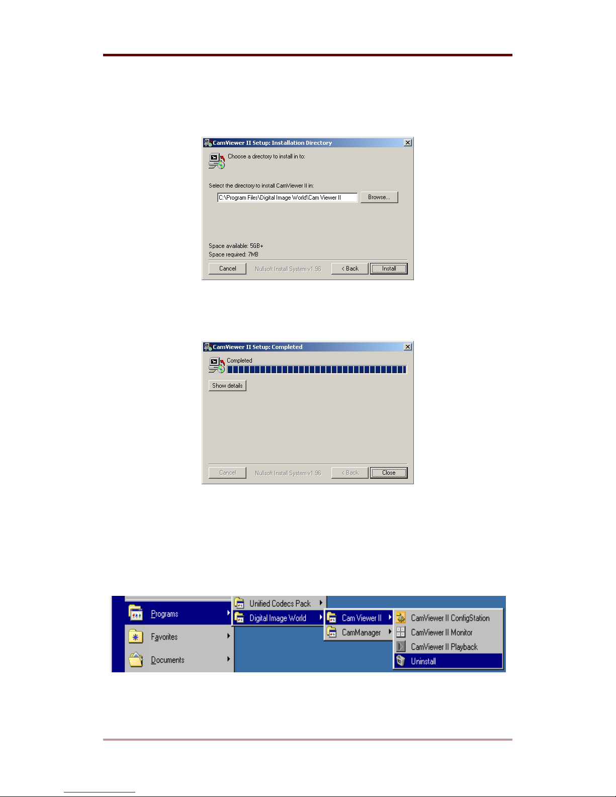
(5) Browse and choose a directory if the default directory is not preferred. Click the ‘Install’
button, after selecting a directory to install.
(6) Click the ‘Close’ button after CamViewer II Setup Program is installed successfully.
5.1.2. Uninstalling
(1) Click Windows ‘Start’ Button
(2) Select and Click ‘Uninstall’ icon to run Uninstall Shield with mouse
(3) CamViewer II will be deleted automatically.
14
2003. 06. 30 (v 1.4)
WEBGATE Inc.
Page 15
Installing & Connecting i-Rec B104
5.2. Connecting to i-Rec B104
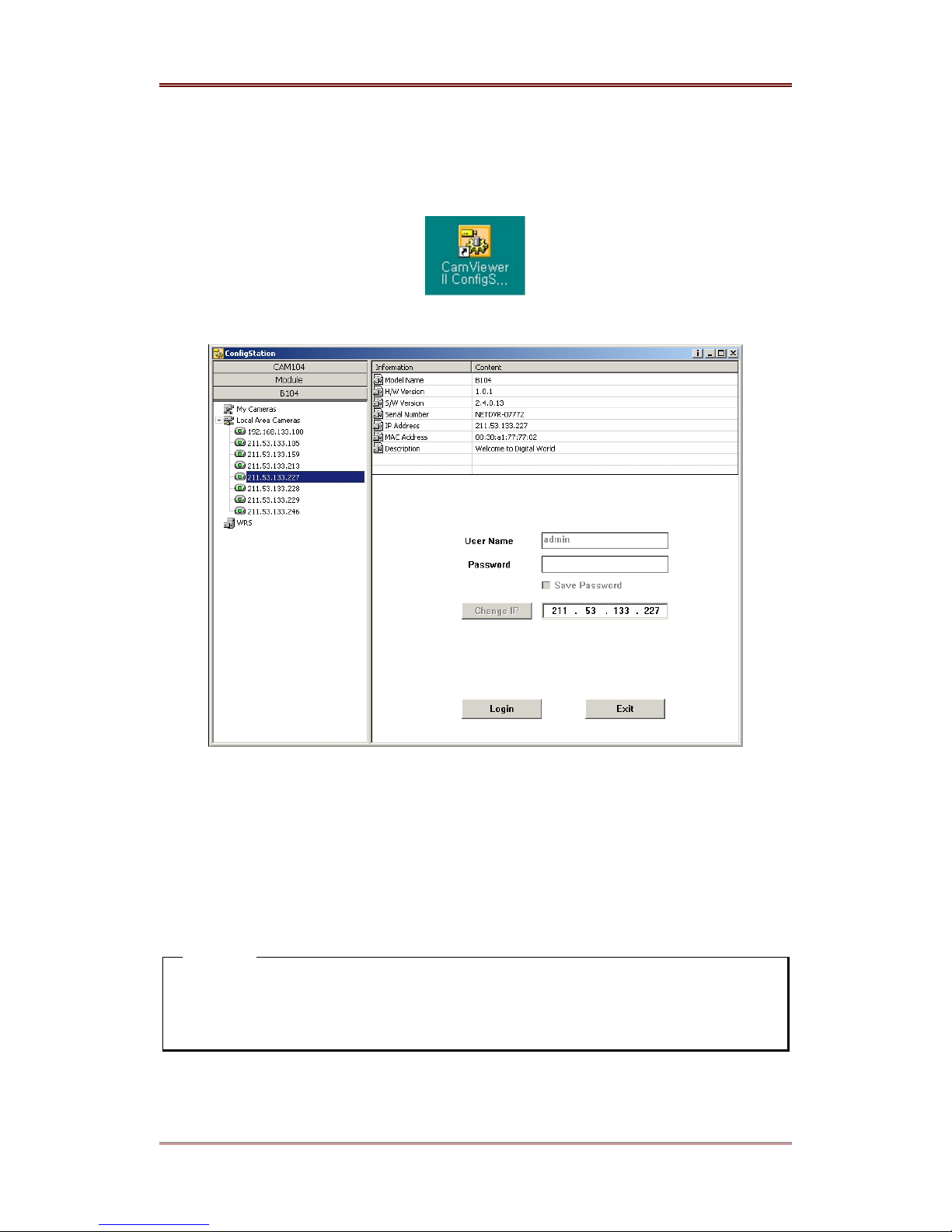
(1) Click icon on desktop to run “ConfigStation” program
(2) Select B104 folder on the left top of program.
(3) Click the symbol ‘+’ on the left of “
Local Area Cameras
” to browse all the i-Rec B104s.
(4) Click to select an i-Rec B104 to assign IP Address. The IP address of the selected i-Rec
B104 will appear in the “Change IP” box.
(5) Type new IP address into the “
Change IP
” and Click “Change IP” button. The default
password of i-Rec B104 is “admin” which can be changed at “User Menu” of Configuration
program.
(6) Click “Login” button to Log-in.
<Note>
Enter ‘User Name’ and ‘Password’. ‘User Name’ is fixed as ‘admin’. If the ‘Save Password’ is
checked, there is no need to enter the Password whenever you were to log in. ‘Save
Password’ function may only be utilized if the Cam is registered on the ‘My Cameras’ directory.
WEBGATE Inc.
2003. 06. 30 (v 1.4)
15
Page 16
i-Rec B104 Installing & Connecting
5.3. Setting IP address
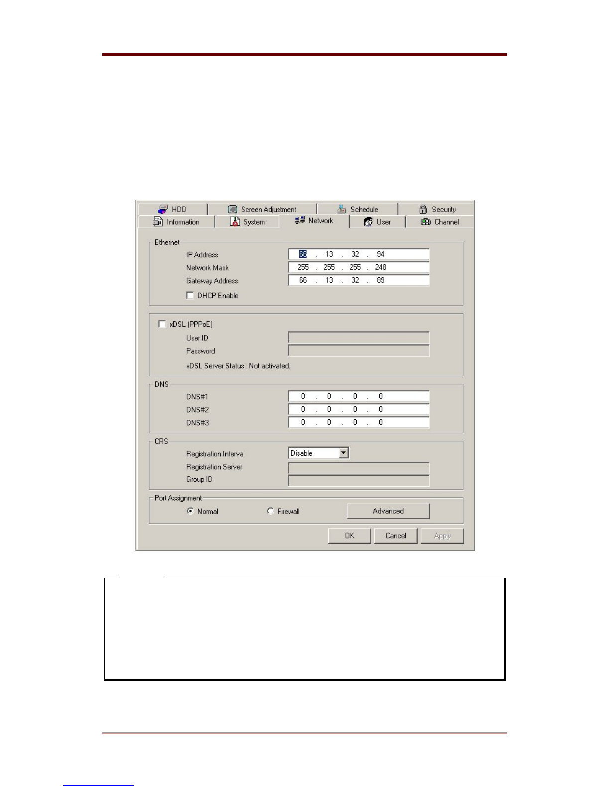
(1) Click “Network” Tab.
(2) Input the assigned values of “
“
Ethernet
” menu.
(3) Click “Apply” button.
IP Address
”, “
Network Mask
”, “
Gateway Address
” into
<Note>
1. Be careful on typing values into this menu. Without correct network address, nobody will
be able to connect to i-Rec B104.
2. Refer to the User’s guide in setup CD-ROM to install i-RecB104 on Dynamic IP network
environment.
3. If a network firewall is installed, change the port number at “Port Assignment”.
16
2003. 06. 30 (v 1.4)
WEBGATE Inc.
Page 17
Installing & Connecting i-Rec B104
5.4. Setting Camera Input Channel
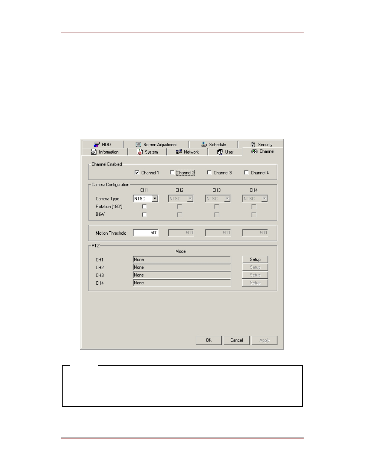
(1) Click “Channel” tab.
(2) Select a connected channel on “
Channel Enable
(3) Set Camera Configuration for the selected channel.
- Camera Type: NTSC or PAL
- Camera Color: Color or Black & White
” menu.
(4) Click “
Apply
” button.
<Note>
1. If channel is selected but the related camera is not connected, recording and monitoring
performance will decrease.
2. i-Rec B104 can’t be used with both NTSC and PAL cameras connected simultaneously.
WEBGATE Inc.
2003. 06. 30 (v 1.4)
17
Page 18
i-Rec B104 Installing & Connecting
5.5 Checking Images of i-Rec B104
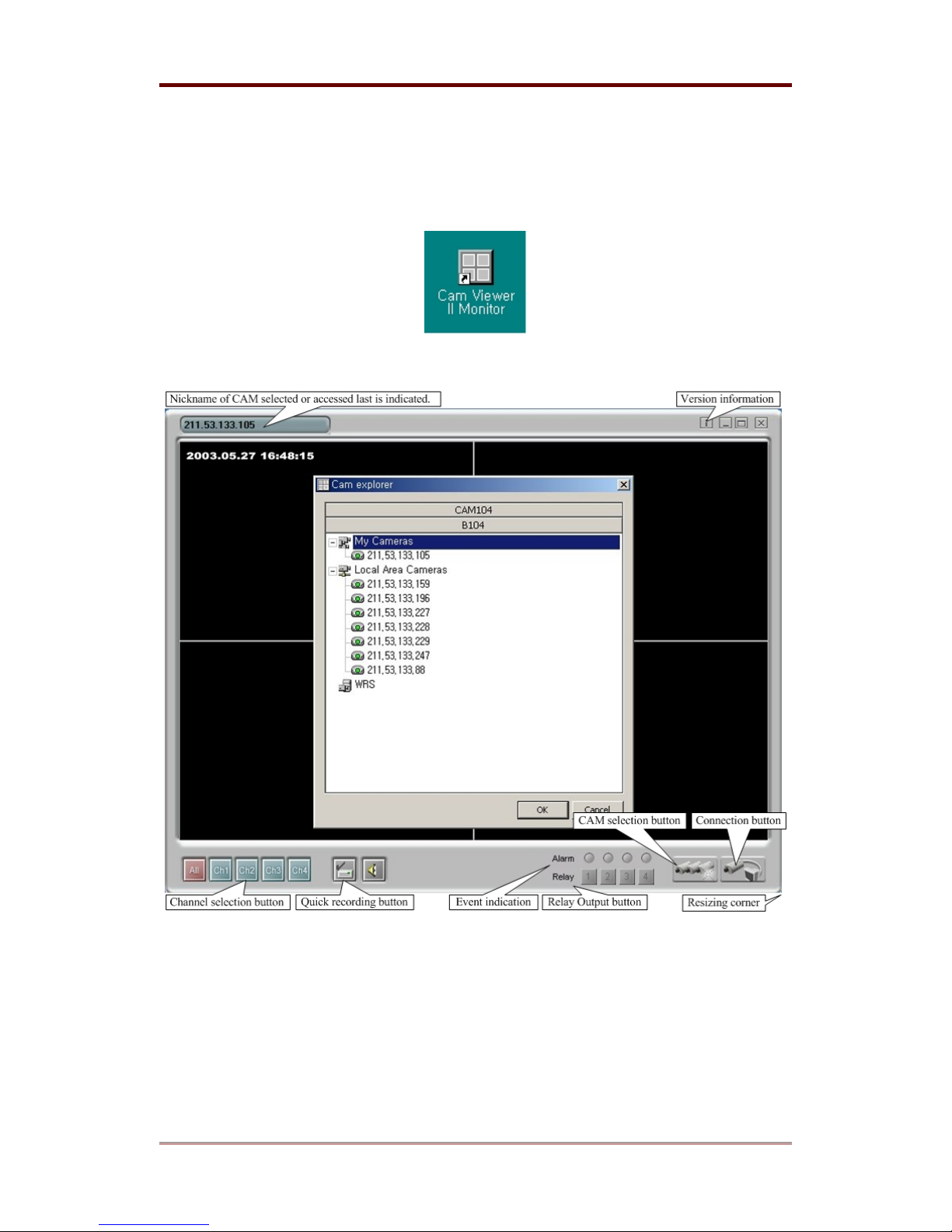
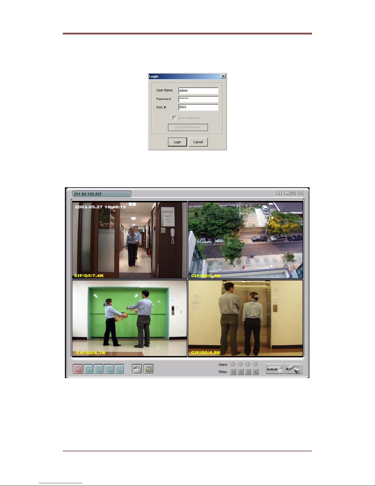
(1) Click the related ICON and run the “Monitor” program.
(2) Click the “Cam Selection” button.
(3) Select “
B104
” folder.
(4) Select i-Rec B104 to view images.
(5) Click “OK” button.
(6) Select the “Cam connection” button.
18
2003. 06. 30 (v 1.4)
WEBGATE Inc.
Page 19
Installing & Connecting i-Rec B104
(7) Enter “
(8) Click “
User Name
” and “
Password
” as “admin” / “admin”.
” button to view images of connected channel.
Login
WEBGATE Inc.
2003. 06. 30 (v 1.4)
19
Page 20
i-Rec B104 Installing & Connecting
6. Installing HDD
6.1. Usable HDD
(1) It is recommended to install only Maxtor brand HDD for i-Rec B104.
Manufacturer: MAXTOR
Series Model Name Size Series Model Name Size
DiamondMax
Plus D740X
(7200rpm)
6L040J(L)2 40GB 4G120J6 120GB
6L060J(L)3 60GB
6L080J(L)4 80GB
DiamondMax
D540X
(5400rpm)
(2) To record at maximum 30 fps, use 7200rpm HDD.
(Maximum speed of 5400 rpm HDD is less than 16frame/sec.)
6.2. HDD Installation Procedure
<Note>
When installing and removing HDD, the i-Rec B104’s power should be turned off.
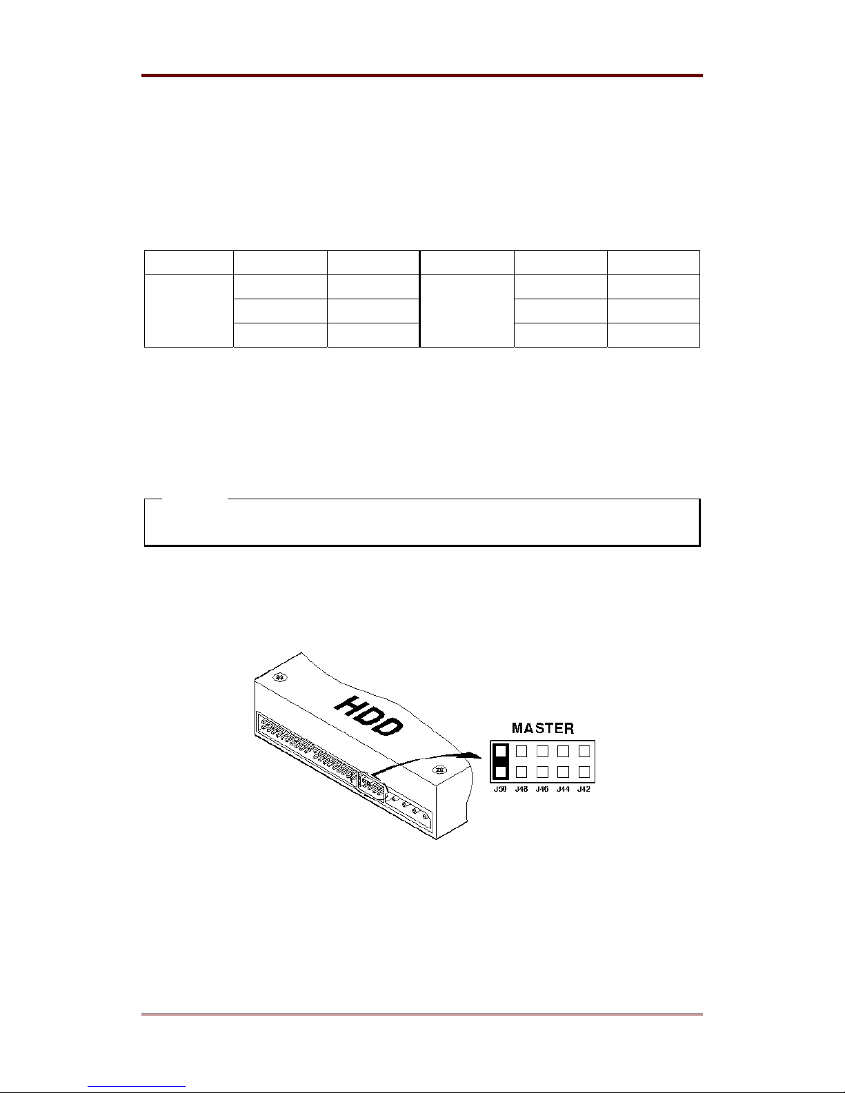
(1) Check that dip switch of HDD is set to “Master” or “Single” mode.
(Default setting of MAXTOR HDD is “
”)
Master
20
2003. 06. 30 (v 1.4)
WEBGATE Inc.
Page 21
Installing & Connecting i-Rec B104
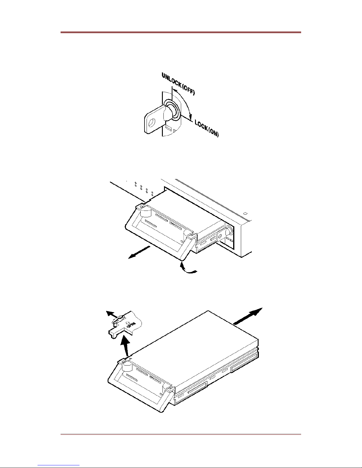
(2) Insert the key into the key hole of HDD rack and turn it counter clock-wise to release.
(3) Pull the handle of HDD rack and remove the HDD case completely from i-Rec B104 rack.
(4) Release the hook and open the cover by pulling lock as indicated in figure below.
WEBGATE Inc.
2003. 06. 30 (v 1.4)
21
Page 22
i-Rec B104 Installing & Connecting
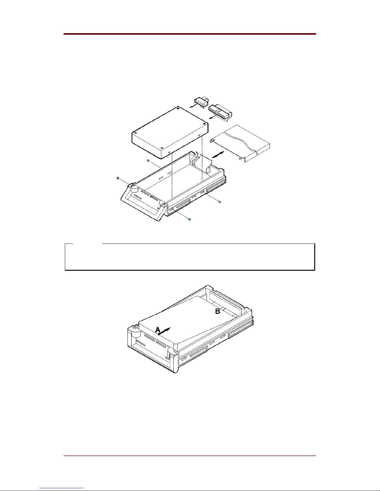
(5) Connect data and power cables to HDD and screw down the HDD to rack. Then close the
cover. (HDD needs to be fixed tightly with screws so that vibration does not damage hard
drive.)
<Note>
When inserting HDD into tray, slide HDD towards the back of the drive tray as indicated
in diagram below.
22
2003. 06. 30 (v 1.4)
WEBGATE Inc.
Page 23
Installing & Connecting i-Rec B104
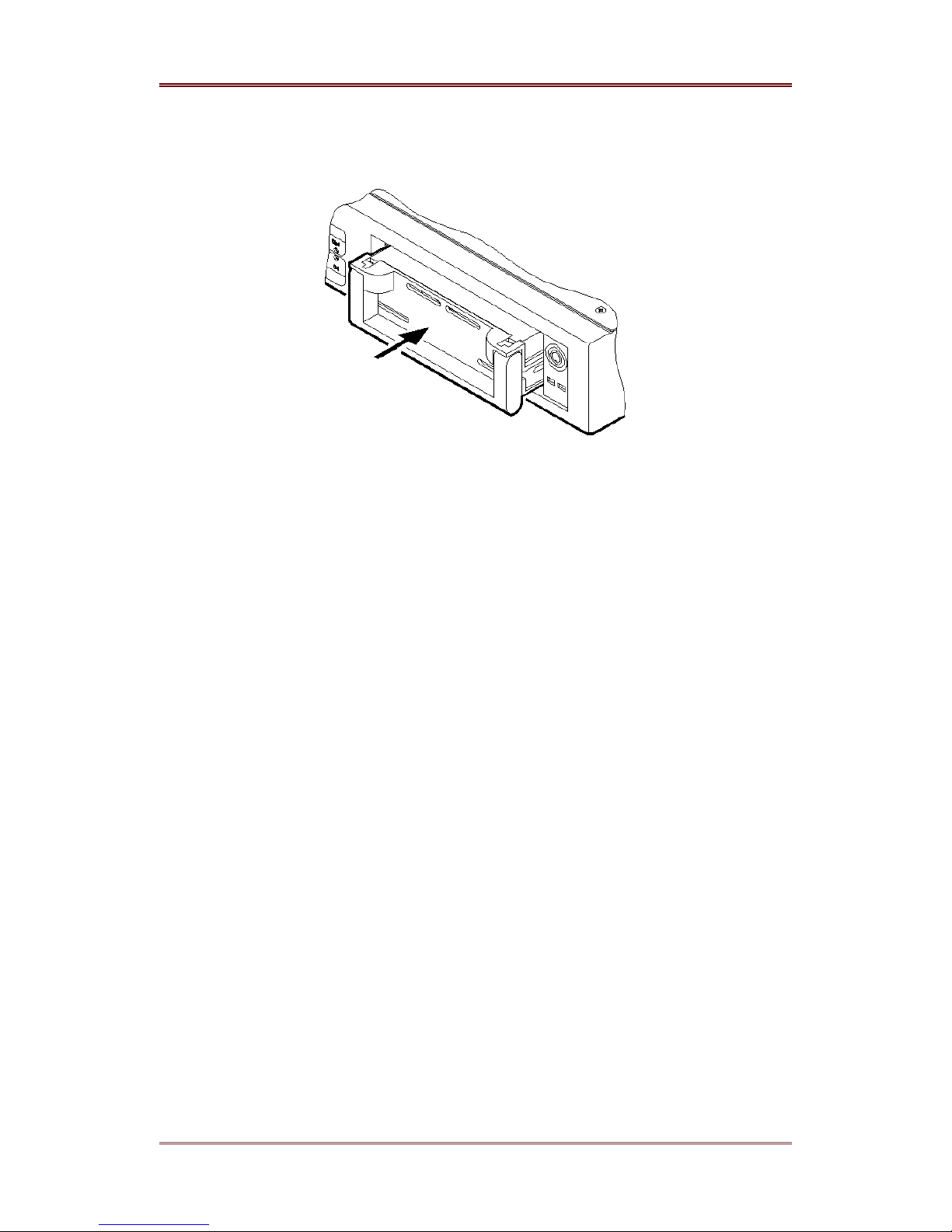
(6) Pull handle down and push the HDD case into the rack completely.
(7) Insert the key and turn it clock wise to re lock the rack.
(8) Check whether the newly installed HDD operates normally, refer to the “Image Recording &
Playback” chapter.
WEBGATE Inc.
2003. 06. 30 (v 1.4)
23
Page 24
i-Rec B104 Installing & Connecting
7. Recording & Playback
After installing HDD, please follow below procedures at the ConfigStation program in order to
record images into HDD
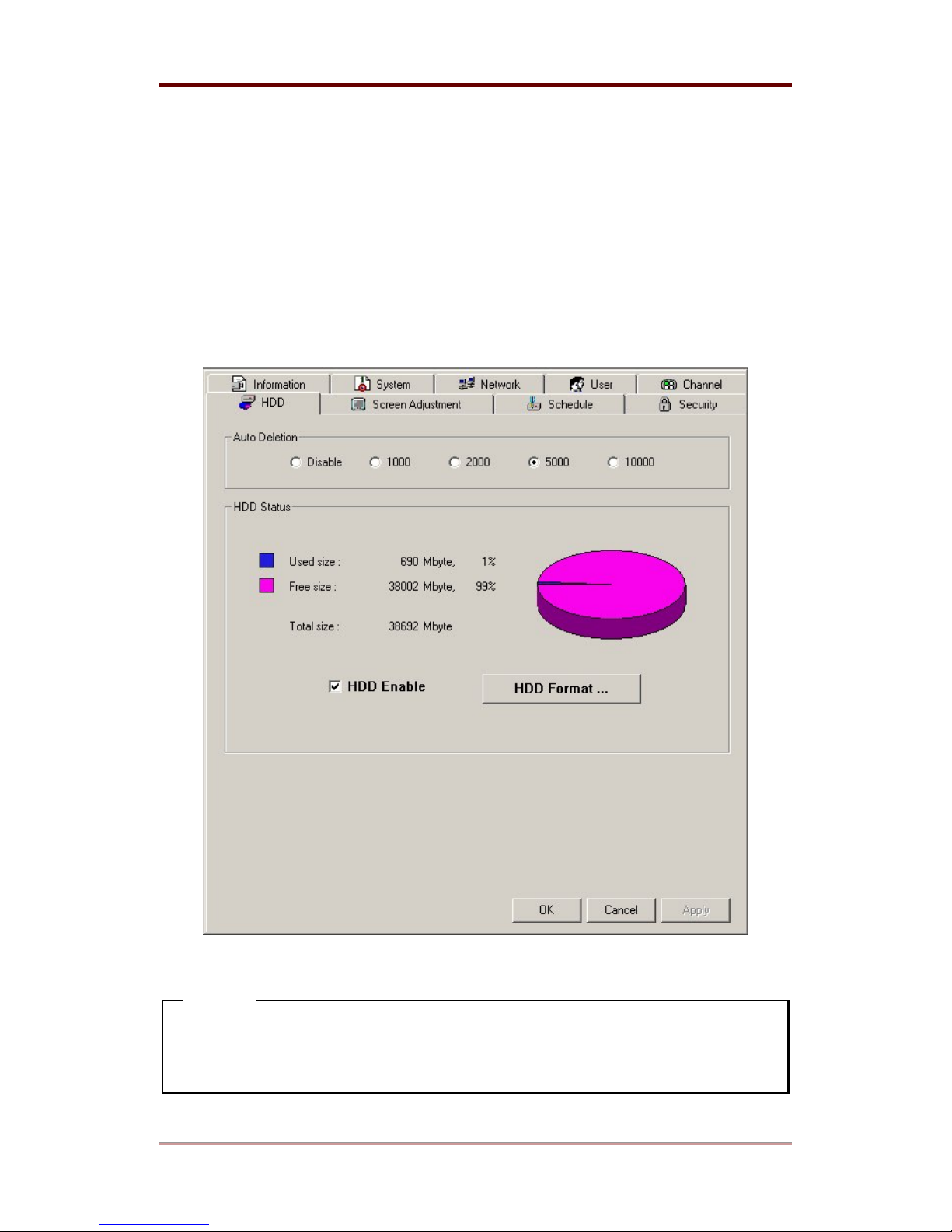
7.1 Setting HDD
(1) Click the “
HDD”
tab.
(2) Check the “HDD Enable” combo box and click “HDD Format…” button.
(3) When the HDD format is complete, click “
<Note>
Auto Deletion is for deleting images from the earliest frame recorded after the HDD is full. By
activating this function, B104 will keep on recording new images by deleting already recorded
images.
24
” button.
Apply
2003. 06. 30 (v 1.4)
WEBGATE Inc.
Page 25
Installing & Connecting i-Rec B104
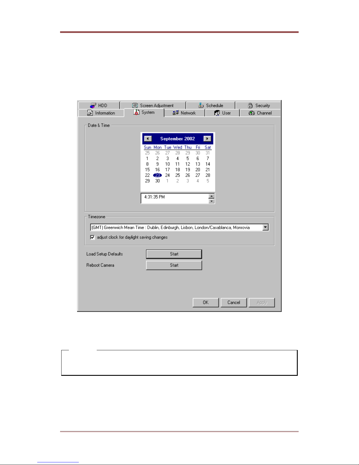
7.2. Setting Time
(1) Click the “System” tab.
(2) Configure the place, time, and date according to the configuration where the i-Rec B104 is
installed.
(3) Click “
Apply
” button.
<Note>
The B104 can be synchronized to the Administrator’s PC as long as PC is set for the same
time zone.
WEBGATE Inc.
2003. 06. 30 (v 1.4)
25
Page 26
i-Rec B104 Installing & Connecting
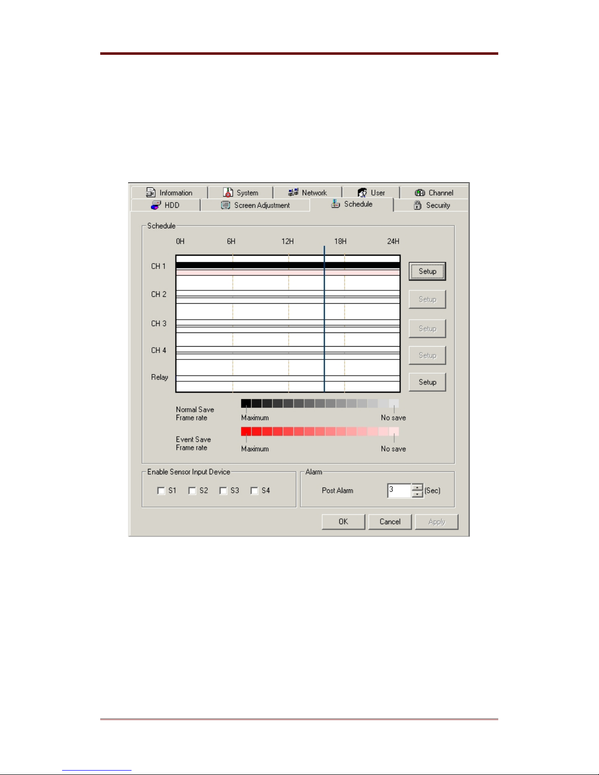
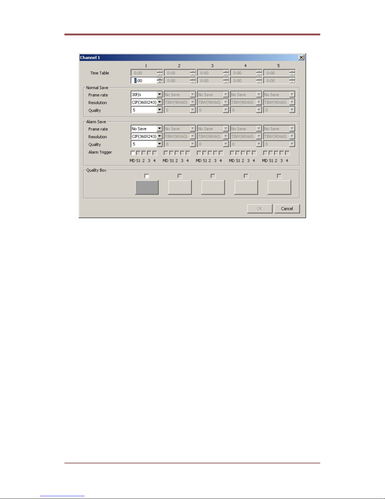
7.3. Setting Recording Schedule
(1) Click “Schedule” tab.
(2) Please click “Setup” button in the “Record Schedule” box to configure recording schedule of
the channel to which camera is connected.
(3) Set up the recording conditions in normal and event time and click the “OK” button.
26
2003. 06. 30 (v 1.4)
WEBGATE Inc.
Page 27
Installing & Connecting i-Rec B104
(4) Click “Apply” button after configuring each channel.
WEBGATE Inc.
2003. 06. 30 (v 1.4)
27
Page 28
i-Rec B104 Installing & Connecting
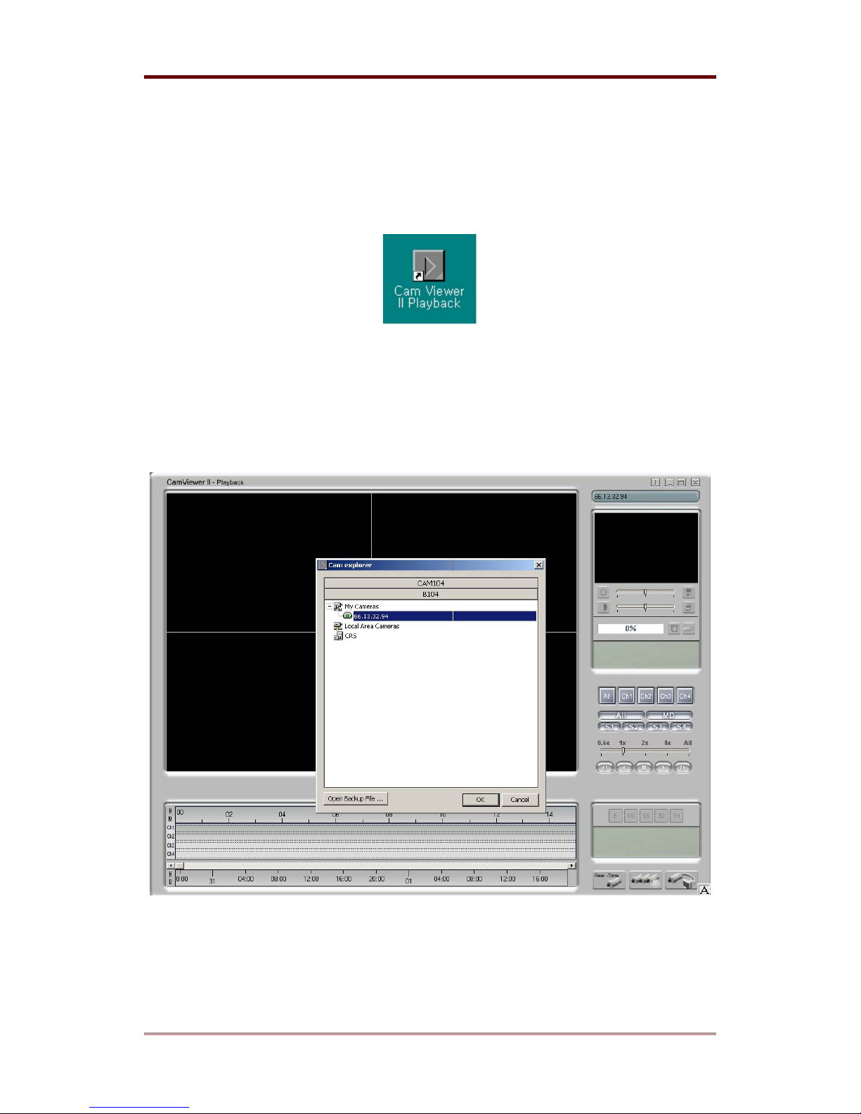
7.4. Playback
(1) Execute “Playback” program by clicking the Cam Viewer II Playback ICON on the PC
Desktop.
(2) Click the button for camera selection on the lower right of the screen.
(3) Select the
B104
folder.
(4) Select the i-Rec B104 in which images have been recorded.
(5) Click “OK” button.
(6) Click the camera connection button.
28
2003. 06. 30 (v 1.4)
WEBGATE Inc.
Page 29
Installing & Connecting i-Rec B104
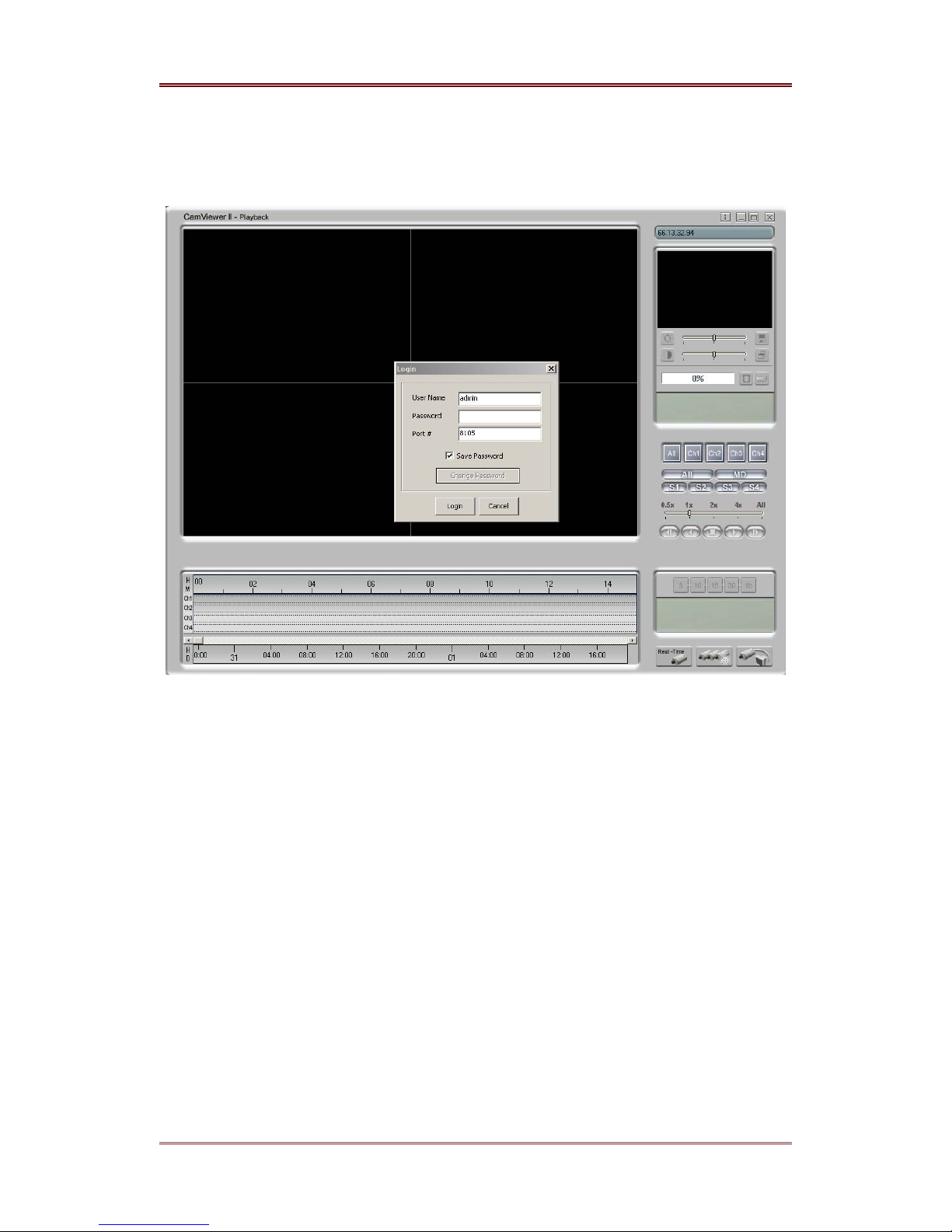
(7) Input “
admin
” and “
” in the log-in input box of “
admin
User Name
” and “
(8) Click “Login” button, and view the images recorded in i-Rec B104.
Password
”.
WEBGATE Inc.
2003. 06. 30 (v 1.4)
29
Page 30
i-Rec B104 Installing & Connecting
8. Input / Output
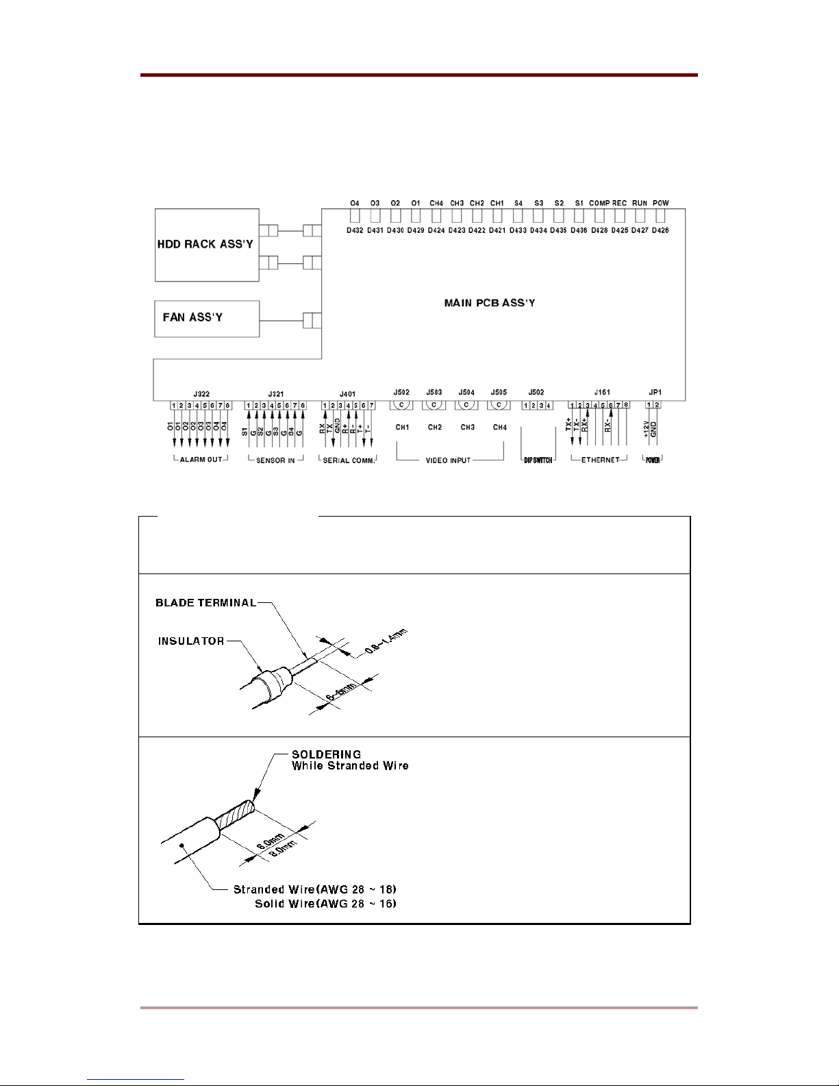
The electrical diagram of i-Rec B104
<Note> Trimming wire
When connecting a wire to a terminal block, follow the instructions below. Note the different
types of wire that can be used.
(1) Compress the wire with the appointed
blade terminal. Use an insulator against
electric shock.
(2) Stranded Wire: Peel off the wiring
cover 8~10mm and solder it. Wire gage
should be AWG 18 ~ 28.
(3) Solid Wire: Peel off the wiring cover
8~10mm and solder it. Wire gage should
be AWG 16 ~ 28.
30
2003. 06. 30 (v 1.4)
WEBGATE Inc.
Page 31
Installing & Connecting i-Rec B104
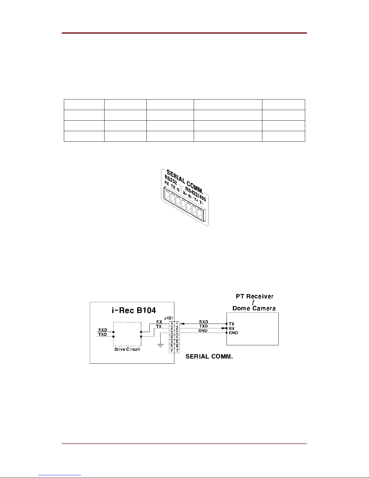
8.1. Connecting Serial Port
8.1.1. Specifications of Serial Port
The followings are serial ports that can be used in i-Rec B104.
Protocol Ch. Max. Distance Max. Driver/Receiver Remarks
RS-232C 1 About 15 m 1 Driver / 1 Receiver Full Duplex
RS-422 1 About 1.2 Km 1 Driver / 1 Receiver Full Duplex
RS-485 1 About 1.2 Km 32 Driver / 32 Receiver Half Duplex
8.1.2. Serial Port View
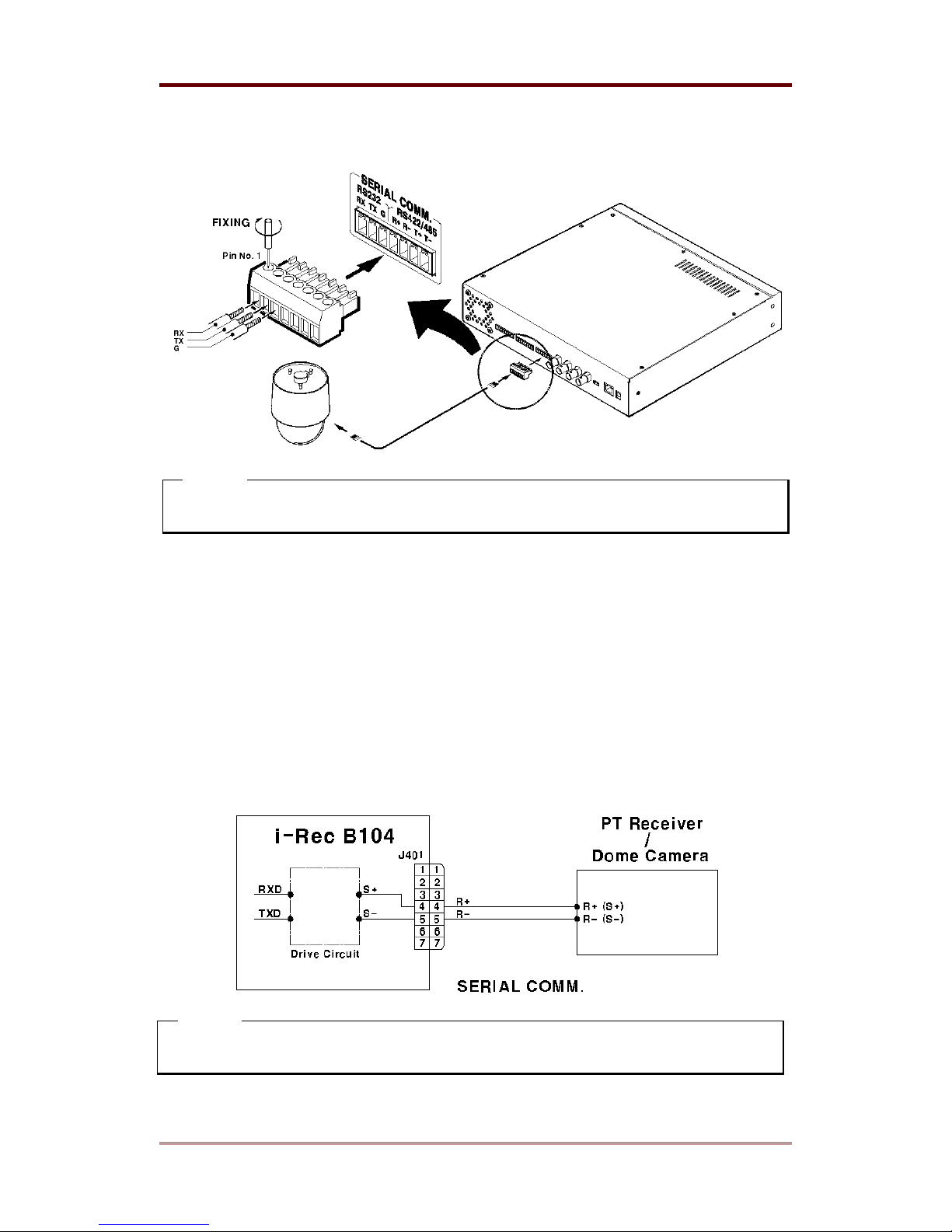
8.1.3. Connecting & setting RS-232 port
RS-232 is for communicating with external devices, resetting system back to default, or
controlling PTZs.
8.1.3.1. Diagram
WEBGATE Inc.
2003. 06. 30 (v 1.4)
31
Page 32
i-Rec B104 Installing & Connecting
8.1.3.2. Connecting
<Note>
Insert the wire as below and spin the screw of terminal block in a clockwise direction.
8.1.3.3. Setting
Access i-Rec B104 with CamViewer program and configure RS232C port suitably after
connecting to external device.
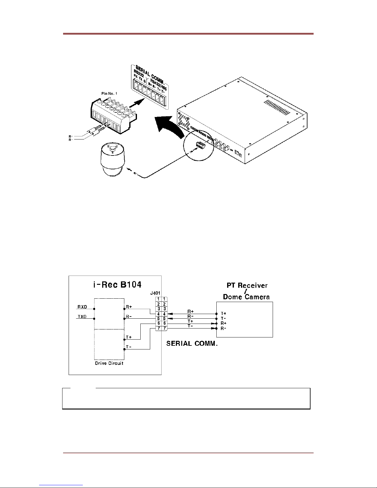
8.1.4. Connecting & setting RS-485 port
RS-485 is used for controlling PTZ. RS-485 is suitable for faster responsiveness of controls and
for further physical distance of cameras than RS-232C.
8.1.4.1. Diagram
<Note>
Some devices require connecting GND port of external device for stable operation.
32
2003. 06. 30 (v 1.4)
WEBGATE Inc.
Page 33
Installing & Connecting i-Rec B104
8.1.4.2. Connecting
8.1.4.3. Setting
Access i-Rec B104 with CamViewer program and configure RS485 port suitably after
connecting with external device.
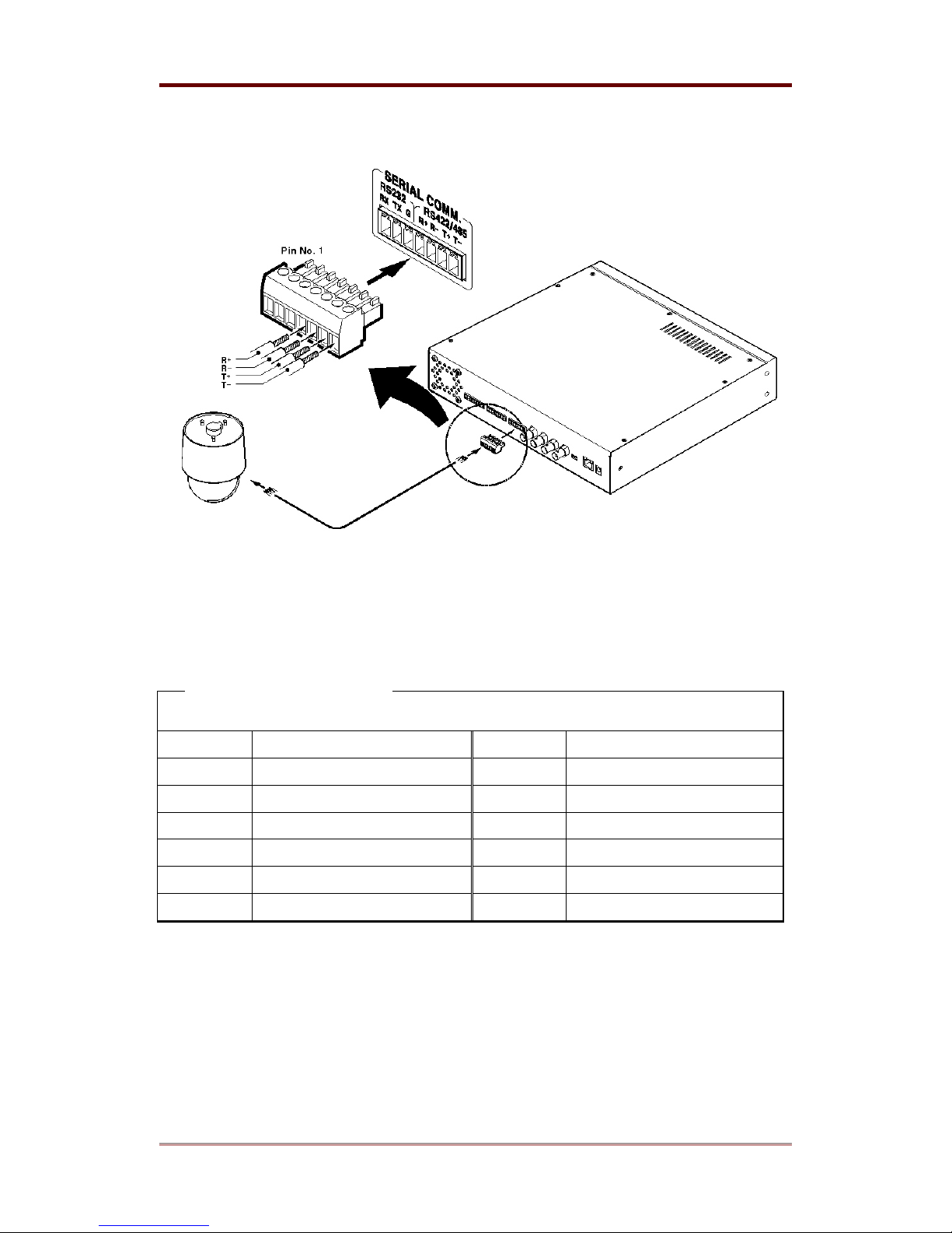
8.1.5. Connecting & setting RS-422 port
8.1.5.1. Diagram
<Note>
Some devices require connecting GND port of external device for stable operation.
WEBGATE Inc.
2003. 06. 30 (v 1.4)
33
Page 34
i-Rec B104 Installing & Connecting
8.1.5.2. Connecting
8.1.5.3. Setting
Access i-Rec B104 with CamViewer program and configure RS422 port suitably after
connecting to external device.
<Note> The supported PTZ
Manufacturer
Model
Manufacturer
Model
Philips Auto Dome LG GAC-PT2
Philips TC8560X-4 Sony EVi-D3x
Pelco ERD97P21-U KukJae KRS-3200
Pelco BDD5-M SungJin SJ3728R1
Sensormatic RAS716LS Samsung SRX100B
VT VPT-4x LILIN Fast Dome
34
2003. 06. 30 (v 1.4)
WEBGATE Inc.
Page 35
Installing & Connecting i-Rec B104
8.2. Connecting Alarm Output
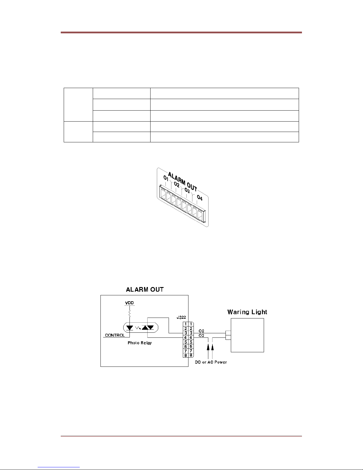
8.2.1. Specifications of Alarm Output
In order to run alarm output of i-Rec B104 normally, the following conditions are required.
Output Ch. 4Ch. Photo relay differential outputs
Spec.
Rating
Output type Dry contact
Connecting type Connecting the trimmed wire to terminal block
DC MAX. 250V, 100mA
AC MAX. 250V, 100mA (Peak to Peak)
8.2.2. Alarm output port view
8.2.3. Connecting & Setting
8.2.3.1. Diagram
When connecting, be careful not to exceed the rated values. Connect O1 ~ O4 with referring to
“3.4.2 Connecting”. The following figure is for connecting a warning light. Output port can be
connected regardless of AC or DC. Be careful not to exceed the rated values.
WEBGATE Inc.
2003. 06. 30 (v 1.4)
35
Page 36
i-Rec B104 Installing & Connecting
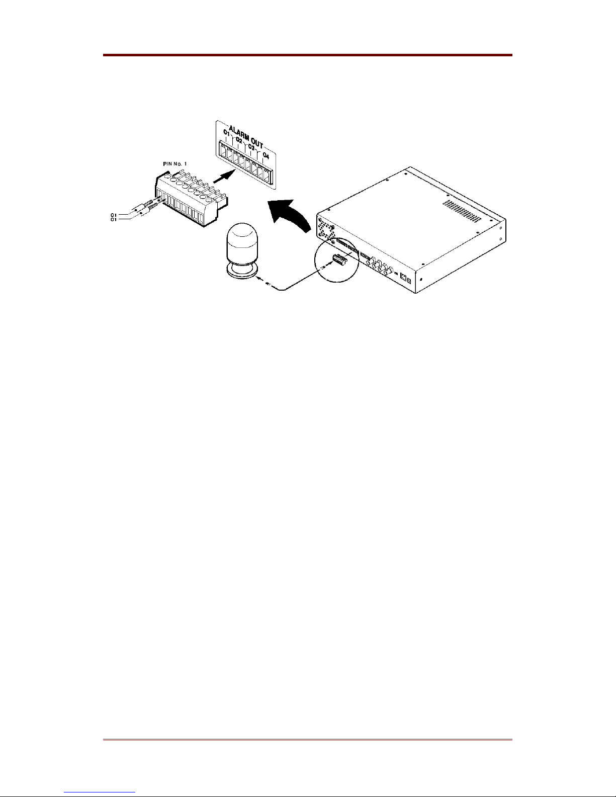
8.2.3.2. Connecting
The above figure shows how to connect a warning light to i-Rec B104. For connecting wire,
please refer to manual of related warning light and “Trimming wire” part of this manual. Insert
the wire and spin the screw of terminal block with flathead “-“shaped driver.
8.2.3.3. Setting
Access i-Rec B104 with CamViewer program and configure alarm output.
36
2003. 06. 30 (v 1.4)
WEBGATE Inc.
Page 37
Installing & Connecting i-Rec B104
8.3. Connecting Sensor Input
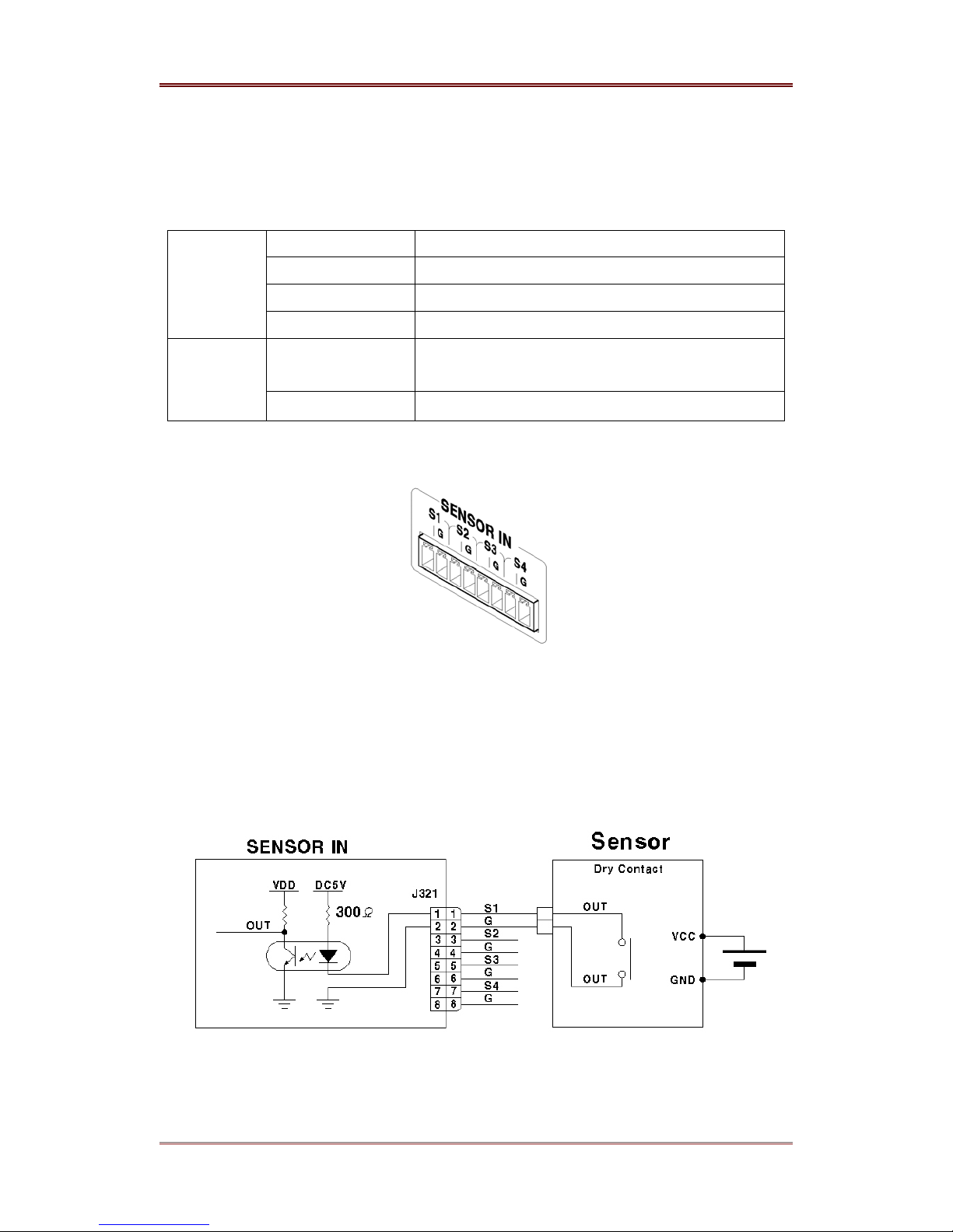
8.3.1. Specifications of Sensor Input
In order to run sensor input of i-Rec B104 normally, the following conditions are required.
Input Ch. 4Ch. Photo coupler differential inputs
Spec.
Performance
Input type N.C. (Normal Close) type
Supported sensor Dry contact
Connecting Connecting the trimmed wire to terminal block
Available input pulse
range
Output current Typical DC 12mA
Min. 500ms
8.3.2. Sensor Input Port View
8.3.3. Connecting & Setting
8.3.3.1. Diagram
Connect S1 ~ S4 with referring to “2.4.2 Connecting”. The following figure is for connecting a
dry contact. When connecting a non- dry contact type of sensor (e.g. Open collector output)
please contact WEBGATE’s Customer Support team.
WEBGATE Inc.
2003. 06. 30 (v 1.4)
37
Page 38
i-Rec B104 Installing & Connecting
8.3.3.2. Connecting
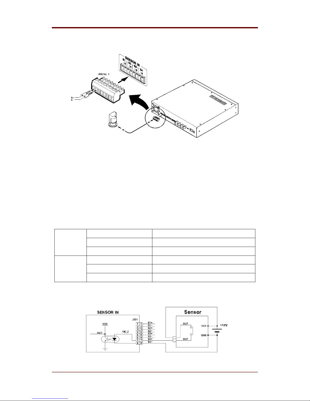
The above figure illustrates connecting a sensor to i-Rec B104. For connecting wires, please
refer to manual of related sensor and “Trimming wire” part of this manual. Insert the wire and
spin the screw of terminal block with flathead “-“shaped driver.
8.3.3.3. Setting
Access i-Rec B104 with CamViewer program and configure sensor input.
8.3.4. Connecting sensors for 1.0 or below main version PCB of i-Rec B104
Previous versions of model’s sensor circuit are different from current one.
Input Ch. 4Ch. Photo coupler differential inputs
Spec.
Performance
Diagram
Input type N.C. (Normal Close) type
Connecting Connecting the trimmed wire to terminal block
Available input pulse range Min. 500ms
Recommended input voltage DC +12V (±10%)
Recommended input current Typical DC 10mA
38
2003. 06. 30 (v 1.4)
WEBGATE Inc.
Page 39
Installing & Connecting i-Rec B104
8.4. Connecting Impedance Setup Switch for Video Input
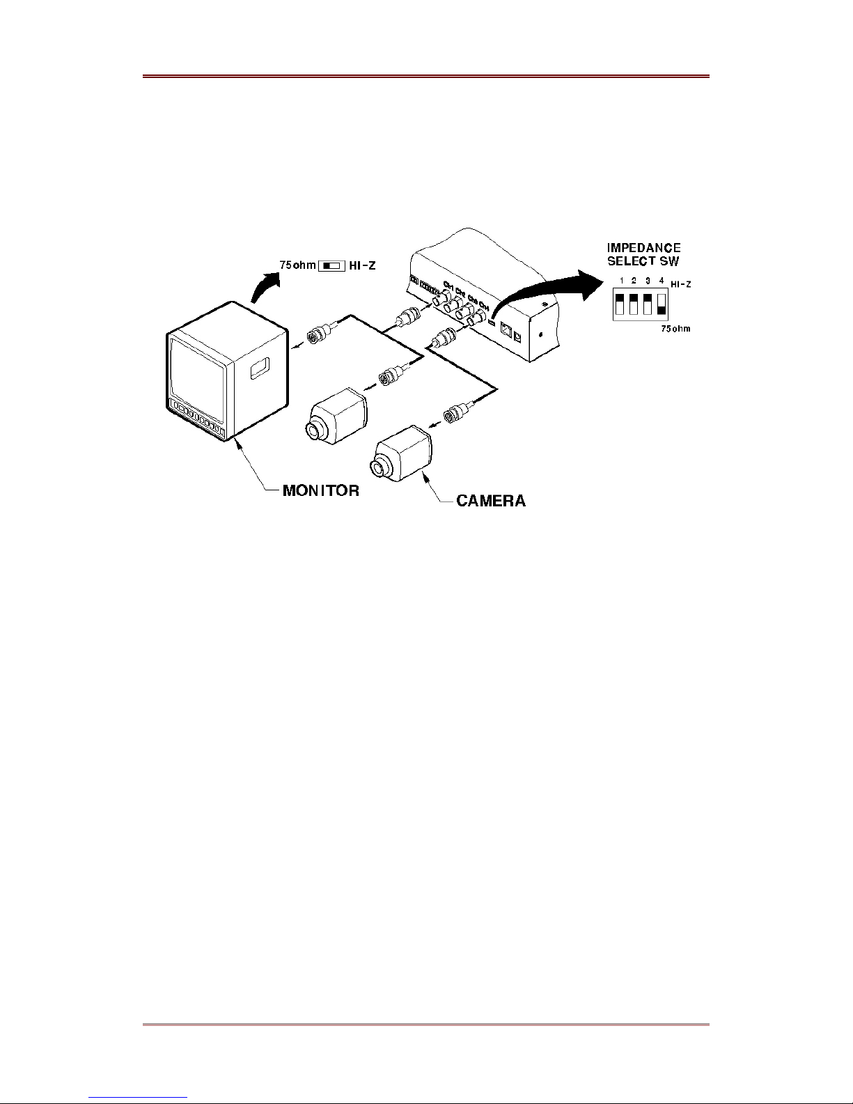
When one video output is connected to several inputs (e.g. CCTV monitor, i-Rec) as below, the
impedance of one input should be 75 ohm.
The impedance will be set as 75ohm by selecting 75ohm.
If you select
Hi-z
, the
impedance
will be
unlimited
.
8.5. Video Input
4 video inputs for external cameras can be connected Please refer to the above figure for
connecting.
WEBGATE Inc.
2003. 06. 30 (v 1.4)
39
Page 40

i-Rec B104 Appendix
APPENDIX
APPENDIX
40
2003. 06. 30 (v 1.4)
WEBGATE Inc.
Page 41

Appendix i-Rec B104
#1. Frequently Asked Question (FAQ)
#1.1. About i-Rec B104’s Feature
What is i-Rec B104?
i-Rec B104 is a 4-channel box style DVR with a Web server of embedded Linux, a
networking device, and a HDD (HDD Rack). Since i-Rec B104 is a Web server, it does not
need to be connected to other servers. By installing an i-Rec B104 in remote locations, you
can remotely record and monitor the place.
What preparations are needed to install?
No equipment is necessary other than power and network cable
Which algorithm is used to compress digital images?
i-Rec B104 uses Wavelet algorithm to compress digital images. Wavelet is a still-image
based compression algorithm. Still-image based means that i-Rec B104 captures still
pictures. JPEG, the standard algorithm in image compression, is also based on still-image.
i-Rec B104 records and transmits frames rapidly so as to make still images move as in a
motion picture.
MPEG is another standard in image compression, but it is based on motion pictures and
does not capture still images.
What is the difference between Wavelet algorithm and JPEG in compressing digital
images?
Wavelet is more efficient than JPEG by 30-300%. Higher efficiency of Wavelet comes from
its encoding method. Wavelet algorithm uses DWT (Discrete Wavelet Transform), while
JPEG uses DCT (Discrete Cosine Transform). Due to its efficiency, Wavelet will be adopted
as standard in digital image compressing by the new JPEG2000 standard.
Can i-Rec B104 support multi users at the same time?
It is possible for an administrator and 4 general users to simultaneously access for real-time
monitoring and playback.
WEBGATE Inc.
2003. 06. 30 (v 1.4)
41
Page 42

i-Rec B104 Appendix
What is maximum transmission speed?
i-Rec B104 transmits 30fps (NTSC) / 25fps (PAL) on 10 base-T Network. However, actual
performance can vary depending on performance of user’s PC and network bandwidth.
The maximum transmission speed is 30 frames per second. However, it does not mean that
everyone can receive 30 frames peer seconds since transmission speed also depends on
user PC’s performance and network line capacity.
i-Rec B104 can transmit as well as record at the same time. If i-Rec B104 records images
from 4 channels and transmits live images from all 4 channels, the transmission speed can
be lower compared with another i-Rec B104 that does not record any image but transmits
images from only 1 channel.
Does i-Rec B104 contain Pan/Tilt/Zoom function?
i-Rec B104 has pan/tilt/zoom controlling function in its software. When a pan/tilt mechanism
and zoom lens are equipped to i-Rec B104, Pan, tilt and zoom can be controlled through i-
Rec CamViewer II.
42
2003. 06. 30 (v 1.4)
WEBGATE Inc.
Page 43

Appendix i-Rec B104
#1.2. About i-Rec B104 Installing
What network line is to be used?
For local use, i-Rec B104 can be installed on any local area network (LAN).
For remote use, network lines on a dedicated line (fix IP or dynamic IP address), xDSL line
and Cable Modem line are to be used. PSTN support is not available for now and ‘Dial-in
connection of PSTN’ will be supported in the next version.
User’s PC can utilize any kind of network line including PSTN (telephone line).
What is maximum extension range of network lines?
UTP cable that is used for LAN can be extended up to 100 meters without bridging.
However existing UTP cable can be extended up to 240 meters without bridging.
Is a special rack or case needed when i-Rec B104 is installed outdoors?
i-Rec B104 itself is not weatherproof. Therefore, it is required to be equipped with
weatherproof case, if i-Rec B104 is installed outdoor.
When the network has one fixed IP address and several private IP addresses, can i-
Rec B104 be connected in the network with a private IP address?
It is possible to connect several i-Rec B104s on a Network that has a fixed official IP
address.
For this configuration, Network administrator of the LAN needs to install a router that
supports port-mapping function for local hosts. By mapping i-Rec’s monitoring and playback
ports with several i-Rec’s private IP addresses, user may access corresponding i-Rec.
For example, a router is mapped with hosts as follows.
- Port TCP8001 and 8105 to local address of 192.168.1.5 (1
- Port TCP8002 and 8106 to local address of 192.168.1.6 (2
- Port TCP8003 and 8107 to local address of 192.168.1.7 (3
Then, a user may access the 1
st
i-Rec with the official IP address of the router by setting
st
i-Rec)
nd
i-Rec)
rd
i-Rec)
TCP port 8001 for monitoring or 8005 for playback when one accesses respective program.
WEBGATE Inc.
2003. 06. 30 (v 1.4)
43
Page 44

i-Rec B104 Appendix
When the network only consists of private IP addresses, can i-Rec B104 be
connected on the network?
i-Rec B104 can be connected to LAN having only private IP addresses, as long as the i-Rec
B104 is accessed by local users. However, the whole network can be down, if the network’s
equipment such as a hub is not sufficient to support all the devices appropriately. This
situation occurs if many i-Rec B104s are connected on a network with insufficient bandwidth.
If a firewall is on the network, can i-Rec B104 be installed and work?
Generally, port 80 or port 8080 is open for ordinary data communication, and port 8839 is
for image transmission. But when a firewall is set, these ports may not be used. In order to
solve this problem, CamViewer II uses port 8105
as playback port and port 8001 as
monitoring port for surveillance. If the port is blocked on the network, user should configure
the ports manually.
If a unique port is available under firewall, administrator may unify and fix the port as one.
This is set when ‘Firewall’ is selected at ‘Network’ configuration page of ConfigStation
program.
Is it possible to access i-Rec B104 through Netscape or Internet Explorer?
It is impossible. As i-Rec B104 is a security product, you can only access i-Rec B104 with
‘CamViewer II’ that is provided by WebGate Inc.
A ‘Mismatched Version’ message or similar appears on i-Rec CamViewer II, and I
cannot access i-Rec B104.
This is because the i-Rec CamViewer II is an outdated version compared to i-Rec B104’s
firmware. Install latest version of i-Rec CamViewer to access i-Rec B104.
Video is not seen in i-Rec CamViewer II. What is the problem?
This occurs if you do not select the channels for external CCD Cameras that are connected
to BNC connectors in the rear of i-Rec B104. Select exact channel to which an external
CCD Camera is connected at the ‘Channel’ page in ConfigStation menu of i-Rec
CamViewer II.
44
2003. 06. 30 (v 1.4)
WEBGATE Inc.
Page 45

Appendix i-Rec B104
Which pan/tilt/zoom mechanism can be installed with i-Rec B104?
i-Rec B104 has function to control pan/tilt/zoom mechanism; the mechanism is installed to i-
Rec B104 through its port in the rear. i-Rec B104 has three pairs of pins; RS-232 and RS-
485/ RS-422
i-Rec B104 contains some protocols (Please refer to “<Note> The supported PTZ”. (Page
34). Administrator may utilize any pan/tilt mechanism that satisfies already listed protocols.
The communication protocols vary for each manufacturer. So it is recommended
to buy a pan/tilt mechanism among registered ones.
WEBGATE Inc.
2003. 06. 30 (v 1.4)
45
Page 46

i-Rec B104 Appendix
#2. Utilizing IP Addresses on Local Network
#2.1. Introduction
Most of our business is done via Internet. We play with information by transmitting through e-
mails and searching the Internet. IP address is what we utilize to access the Internet.
Currently used IP addresses are limited. There are 5 classes’, and a network contains many IP
addresses. A network can hold limited IP addresses. The numbers depend on network class.
There are five classes are from A to E, and the most common one is the C class network.
#2.2. IP Construction and Network class
1) IP construction
(xxx: 0 – 255)
xxx xxx xxx xxx
X1 X2 X3 X4
2) Network class
A class: A network that contains IP addresses from 0 to 127 at room ‘X1’.
- Network ID: X1
- Host ID: X2, X3, X4
- There is a total number of 128 A-class networks in the world.
B class
C class
D class: A network that contains IP addresses from 224 to 239 at room ‘X1’.
: A network that contains IP addresses from 127 to 191 at room ‘X1’.
- Network ID: X1, X2
- Host ID: X3, X4
- Total number of B-class networks in the world is 65,534.
: A network that contains IP addresses from 192 to 223 at room ‘X1’.
- Network ID: X1, X2, X3
- Host ID: X4
- It is the most common network in the world, and the total number of C-class networks is
2,097,152.
- D-class network is for multicasting, and it is not allowed for common users.
46
2003. 06. 30 (v 1.4)
WEBGATE Inc.
Page 47

Appendix i-Rec B104
E class
: A network that contains IP addresses from 240 to 225 at room ‘X1’.
- E-class network is reserved.
#2.3. C-class Network
1) Features of Addresses
IP address: Three digits number in room ‘X4’ are for Host ID, and the numbers are from 0 to
255. Among the numbers, 0 is used for Network ID, 1 is used for Router IP (Gateway address)
and 255 is used for Broadcast address. Therefore the numbers from 2 to 244 are IP addresses
that can be assigned to WebEye, i-Rec B104, PC etc.
Network ID
Gateway address: It is an IP address of router that is connecting Internet and local network.
Remote users can access local network over Internet through the gateway (router). Generally
the second number is assigned as Gateway address.
Broadcast address: It is to broadcast all devices that are connected on local network.
Broadcast address is a destination for broadcasting and it is determined by calculating. All
devices connected on local network have the same Broadcast address.
: It is to identify a network. Generally the first number is assigned as Network ID.
Subnet Mask: It is to divide a local network into two remote networks. Subnet mask shows the
IP quantity in a certain network. The numbers that can be used as subnet mask are limited (0, 4,
8, 16, 32, 64, and 128)
2) Network configuration
(1) To use as one network
Network ID: xxx.xxx.xxx.0
Gateway Address: xxx.xxx.xxx.1
Subnet Mask: 255.255.255.0
Broadcast Address: xxx.xxx.xxx.255
IP Addresses: xxx.xxx.xxx.2 – xxx.xxx.xxx.254
WEBGATE Inc.
2003. 06. 30 (v 1.4)
47
Page 48

i-Rec B104 Appendix
(2) To use as two sub-networks (1/2 + 1/2)
Sub-Network ID: xxx.xxx.xxx.0
Gateway Address: xxx.xxx.xxx.1
Subnet Mask: 255.255.255.128
Broadcast Address: xxx.xxx.xxx.127
IP Addresses: xxx.xxx.xxx.2 – xxx.xxx.xxx.126
Sub-Network ID: xxx.xxx.xxx.128
Gateway Address: xxx.xxx.xxx.129
Subnet Mask: 255.255.255.128
Broadcast Address: xxx.xxx.xxx.255
IP Addresses: xxx.xxx.xxx.130 – xxx.xxx.xxx.254
(3) To use as three sub-networks (1/4 + 1/4 + 1/2)
Sub-Network ID: xxx.xxx.xxx.0
Gateway Address: xxx.xxx.xxx.1
Subnet Mask: 255.255.255.192
Broadcast Address: xxx.xxx.xxx.63
IP Addresses: xxx.xxx.xxx.2 – xxx.xxx.xxx.62
Sub-Network ID: xxx.xxx.xxx.64
Gateway Address: xxx.xxx.xxx.65
Subnet Mask: 255.255.255.192
Broadcast Address: xxx.xxx.xxx.127
IP Addresses: xxx.xxx.xxx.66 – xxx.xxx.xxx.126
Sub-Network ID: xxx.xxx.xxx.128
Gateway Address: xxx.xxx.xxx.129
Subnet Mask: 255.255.255.128
Broadcast Address: xxx.xxx.xxx.255
IP Addresses: xxx.xxx.xxx.130 – xxx.xxx.xxx.254
48
2003. 06. 30 (v 1.4)
WEBGATE Inc.
Page 49

Appendix i-Rec B104
(4) To use as four sub-networks (1/4 + 1/4 + 1/4 + 1/4)
Sub-Network ID: xxx.xxx.xxx.0
Gateway Address: xxx.xxx.xxx.1
Subnet Mask: 255.255.255.192
Broadcast Address: xxx.xxx.xxx.63
IP Addresses: xxx.xxx.xxx.2 – xxx.xxx.xxx.62
Sub-Network ID: xxx.xxx.xxx.64
Gateway Address: xxx.xxx.xxx.65
Subnet Mask: 255.255.255.192
Broadcast Address: xxx.xxx.xxx.127
IP Addresses: xxx.xxx.xxx.66 – xxx.xxx.xxx.126
Sub-Network ID: xxx.xxx.xxx.128
Gateway Address: xxx.xxx.xxx.129
Subnet Mask: 255.255.255.192
Broadcast Address: xxx.xxx.xxx.191
IP Addresses: xxx.xxx.xxx.130 – xxx.xxx.xxx.190
Sub-Network ID: xxx.xxx.xxx.192
Gateway Address: xxx.xxx.xxx.193
Subnet Mask: 255.255.255.192
Broadcast Address: xxx.xxx.xxx.255
IP Addresses: xxx.xxx.xxx.194 – xxx.xxx.xxx.254
WEBGATE Inc.
2003. 06. 30 (v 1.4)
49
Page 50
i-Rec B104 Appendix
#3. Setting the fixed IP address on PC
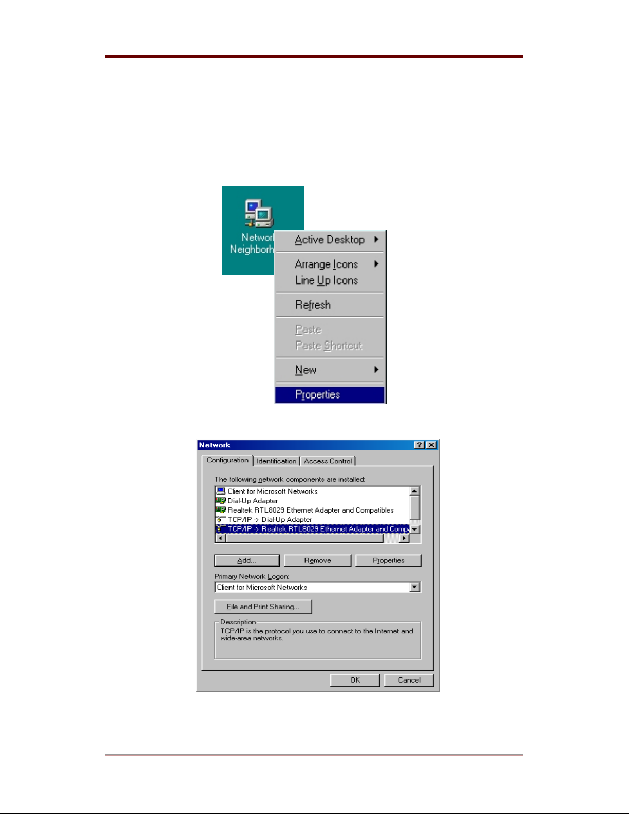
The following shows how to set the fixed IP address on PC with Microsoft’s Windows98.
(1) After selecting “Network Neighborhood” of desktop, press the right button of mouse and
select “Properties”.
(2) Select TCP/IP adapter and press the “Properties” button.
50
2003. 06. 30 (v 1.4)
WEBGATE Inc.
Page 51
Appendix i-Rec B104
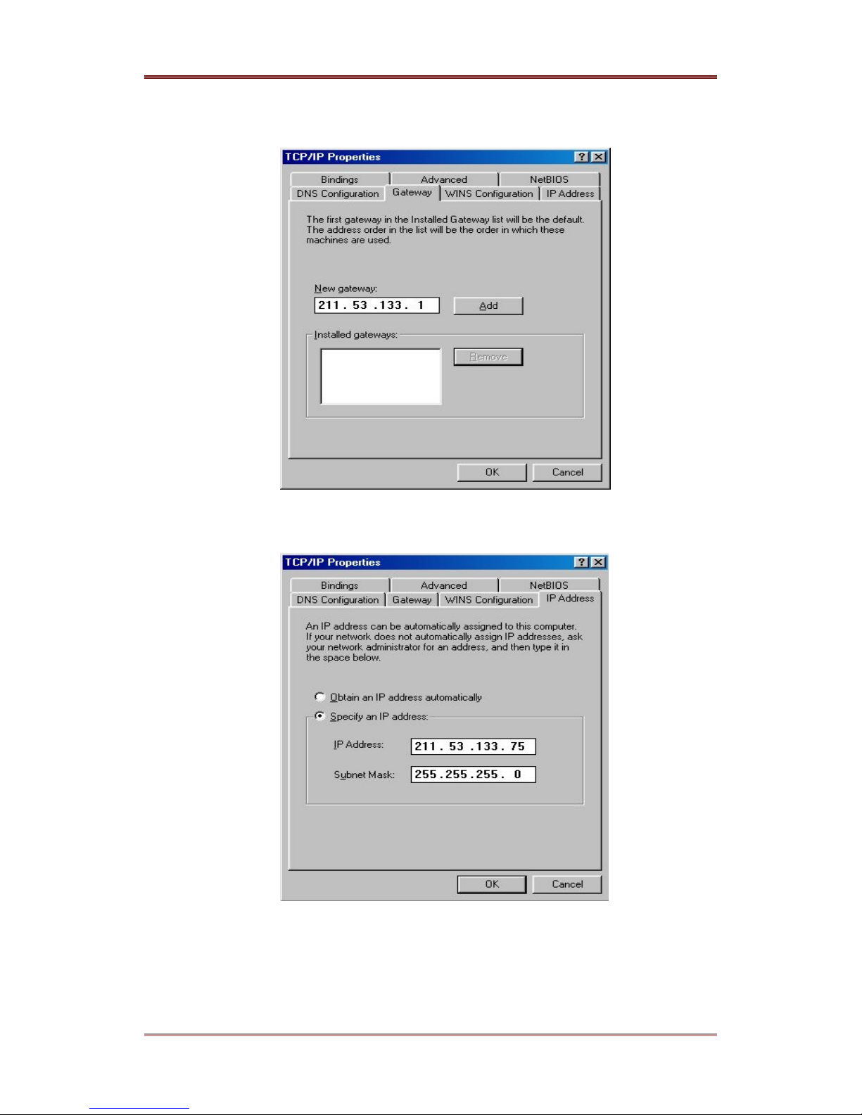
(3) Enter Gateway as following, and press the “Add” button.
(4) Enter IP address and Subnet Mask as following.
WEBGATE Inc.
2003. 06. 30 (v 1.4)
51
Page 52
i-Rec B104 Appendix
#4. CRS Help
#4.1. When using ADSL
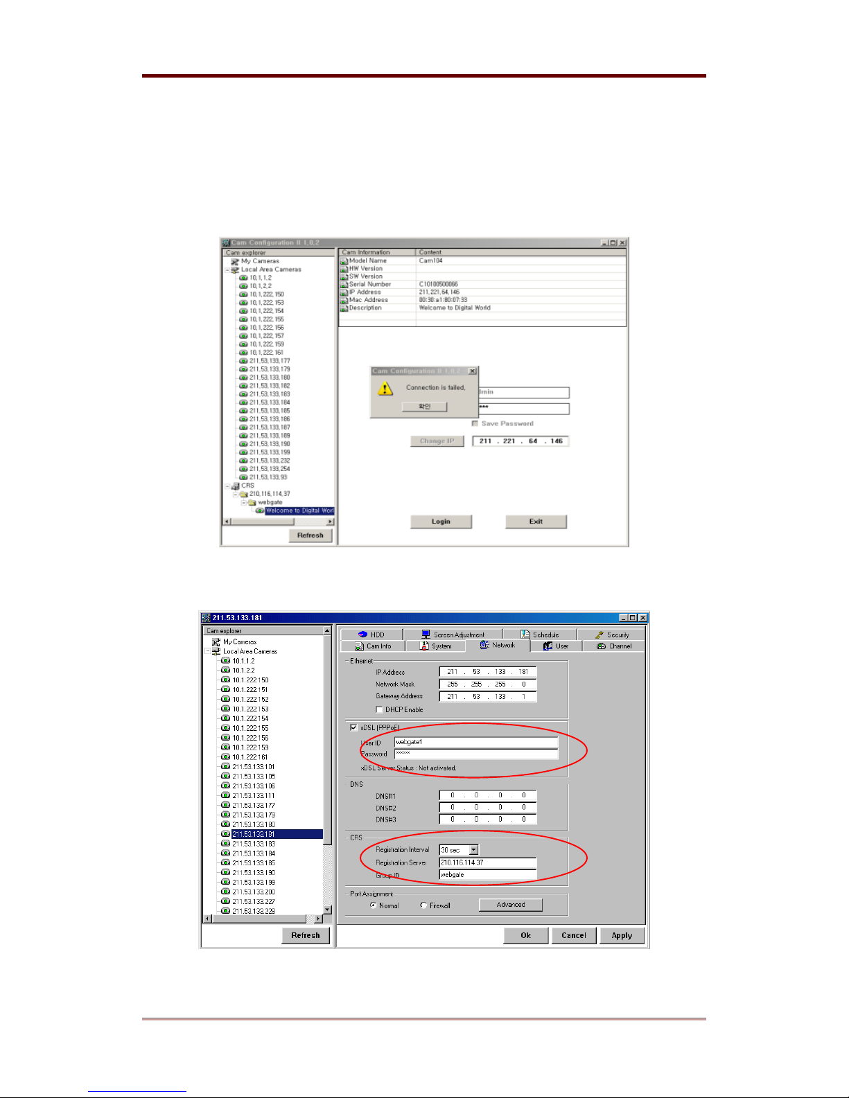
When you can’t access B104 connected to ADSL, check the followings.
(1) Configure each values at xDSL (PPPoE) and CRS of “Network” tab.
52
2003. 06. 30 (v 1.4)
WEBGATE Inc.
Page 53
Appendix i-Rec B104
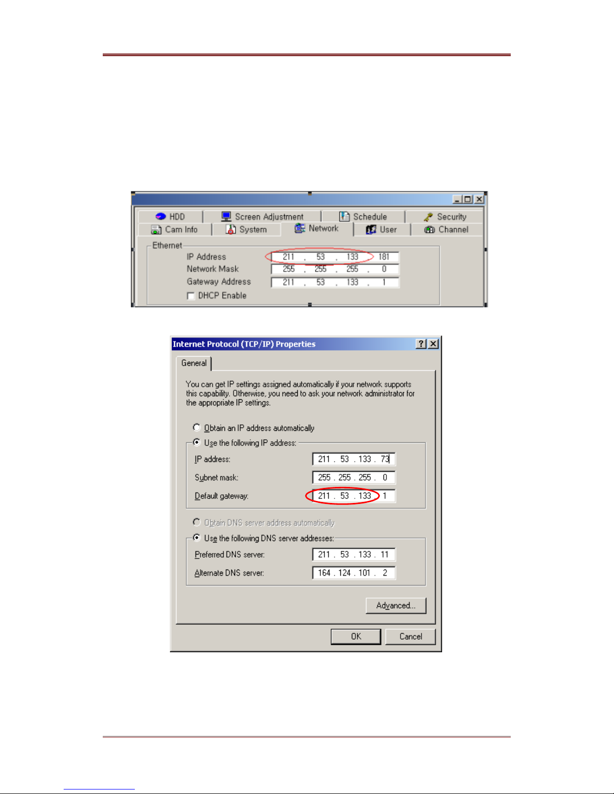
(2) Check whether B104’s IP address is same with PC’s IP address or not.
For example, if B104’s IP address is 211.53.133.181(Figure 1) and PC’s IP address is
211.53.133.73(Figure 2), connection will be failed. If network address part of IP address is same
like ‘211.53.133’, packets that should be transmitted to PC can be transmitted to B104.
[Figure 1]
WEBGATE Inc.
[Figure 2]
2003. 06. 30 (v 1.4)
53
Page 54
i-Rec B104 Appendix
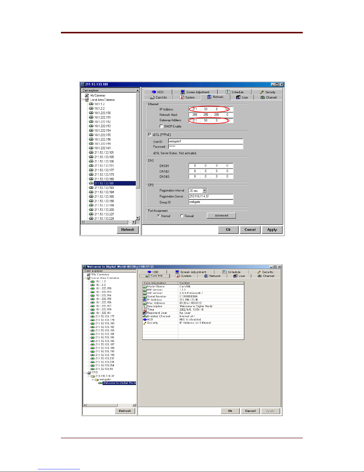
(3) In this case, you have only to change network address part of B104’s IP address after
accessing B104 through local network. For example, you have to change 211.53.133.181 into
211.53.0.181.
(4) After changing network value, reboot B104.
54
2003. 06. 30 (v 1.4)
WEBGATE Inc.
Page 55
Appendix i-Rec B104
#4.2. When resetting local network from ADSL
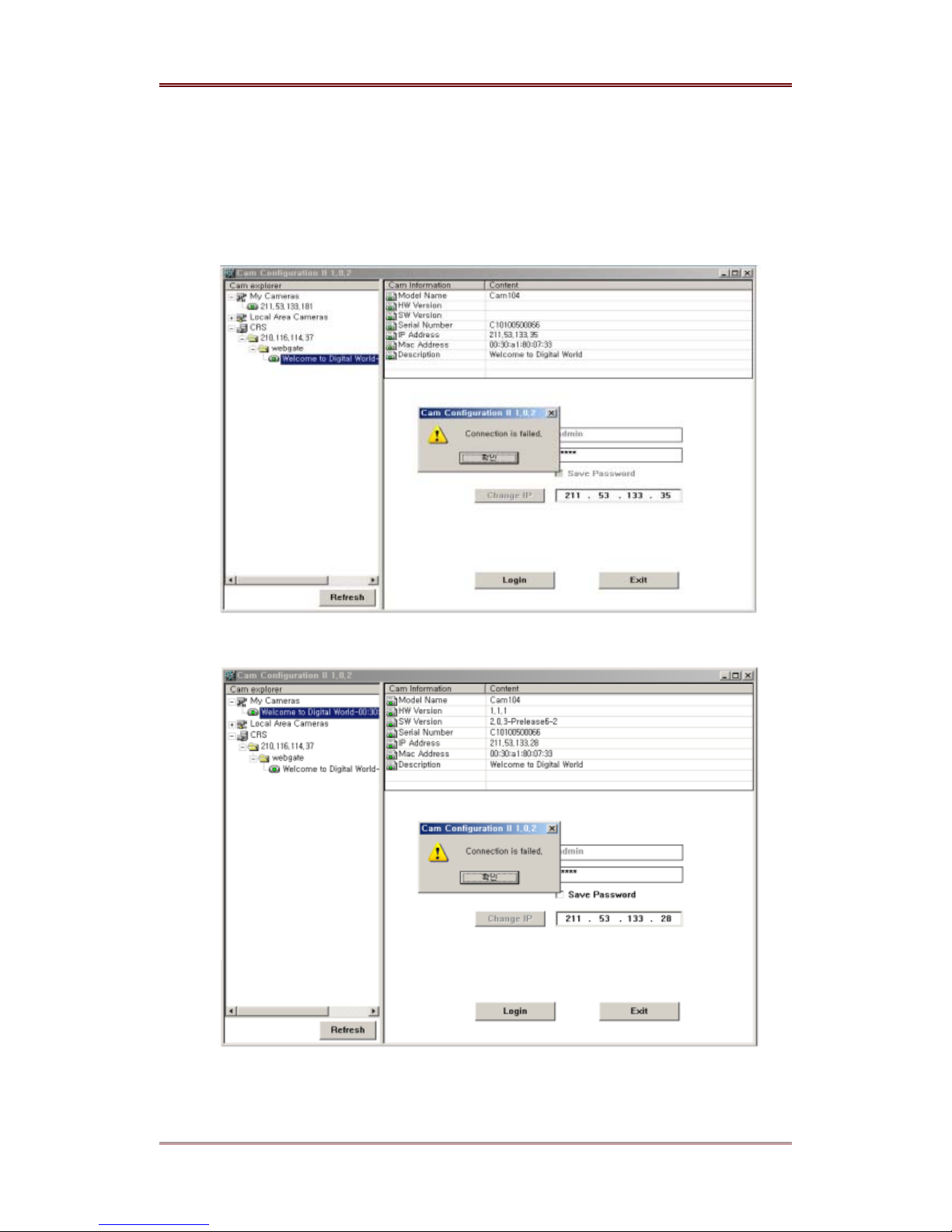
(1) Stop connecting ADSL. When connecting to local network again, B104 can’t be connected
as followings.
(The following example shows when Group ID is set as webgate.)
[Figure 1] When connecting B104 that is registered at My Cameras
[Figure 2] When connecting B104 that is registered at Group ID of CRS
WEBGATE Inc.
2003. 06. 30 (v 1.4)
55
Page 56
i-Rec B104 Appendix
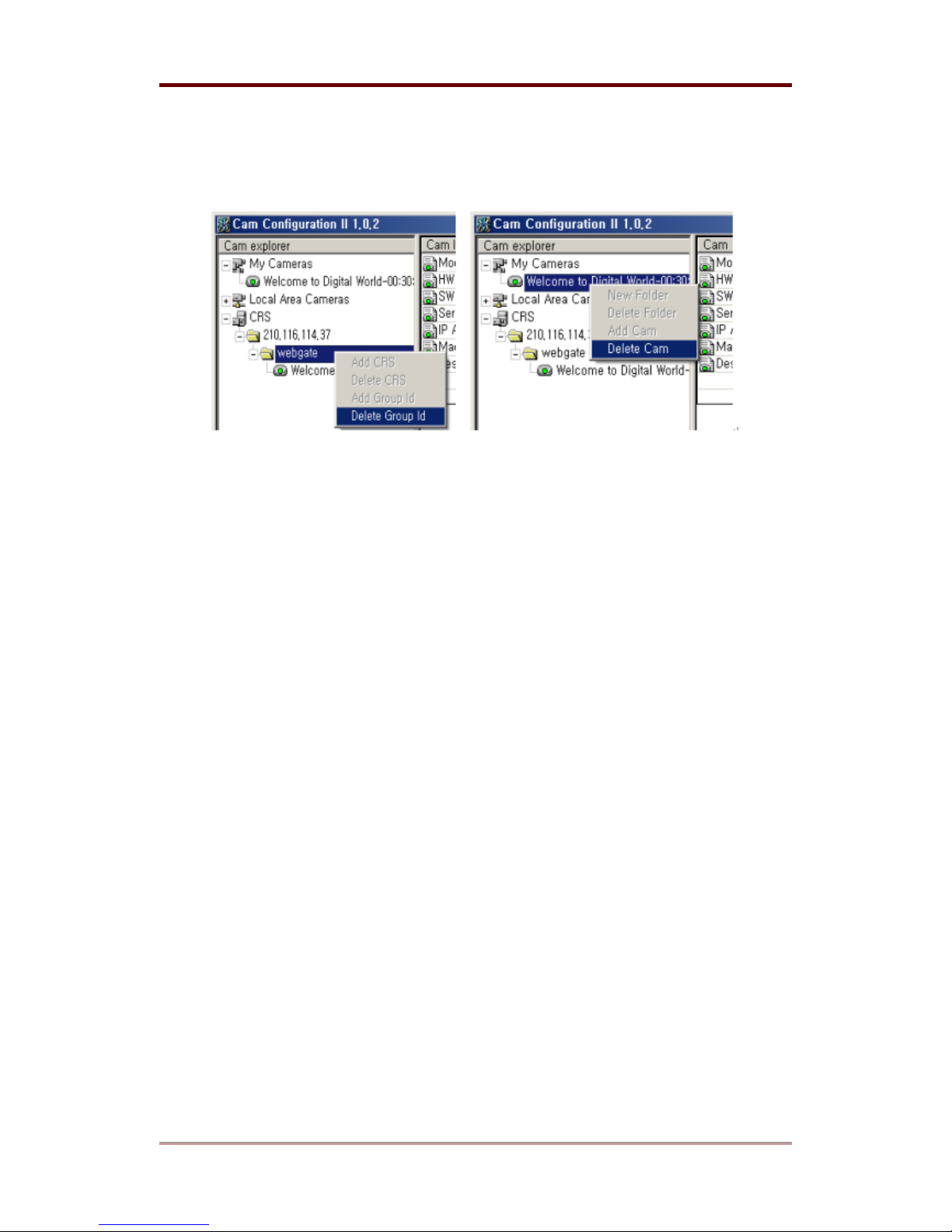
(2) In this case, delete the current Group ID (webgate) of CRS. If same camera is also
registered in My Cameras, both of them should be deleted. When deleting all in both menus, the
B104 shows in Local Area Cameras automatically.
56
2003. 06. 30 (v 1.4)
WEBGATE Inc.
Page 57

Appendix i-Rec B104
(3) User can register the B104 of ‘Local Area Cameras’ to ‘My Cameras’ directory by dragging.
At this time, you should change its IP within the related local network.
WEBGATE Inc.
2003. 06. 30 (v 1.4)
57
Page 58
i-Rec B104 Appendix
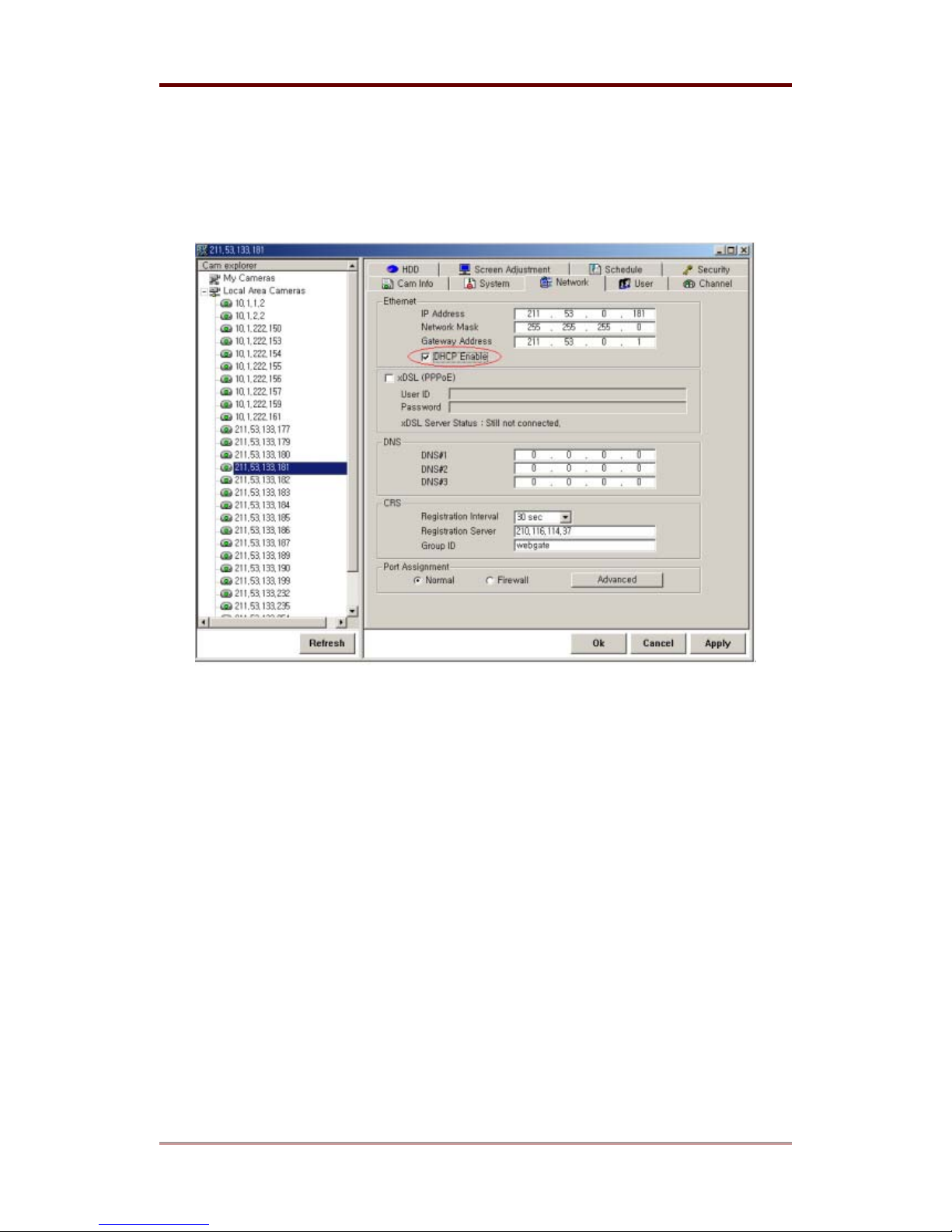
#4.3. When using Cable modem
Check if DHCP Enable is selected. You should not select xDSL (PPPoE).
58
2003. 06. 30 (v 1.4)
WEBGATE Inc.
Page 59
Appendix i-Rec B104
#5. Upgrading i-Rec B104 Firmware
<Warning>
This process is to upgrade i-Rec B104 with new firmware.
Make sure to complete the whole process,. When the process is completed, ‘User Image
Upgrade is complete’ message appears. During the process, do not give physical shock nor
disconnect network and power. Otherwise, your i-Rec B104 can be damaged seriously, which
may result in inappropriate operation or operation failure.
If you failed in upgrading i-Rec B104 firmware or i-Rec B104 does not operate properly after
successful upgrading process, contact WGI distributor in your area.
#5.1. Connecting i-Rec B104 to PC
Connect i-Rec B104 to PC with a crossover cable directly. This connection is recommended.
It is also possible to connect i-Rec B104 to a PC through a HUB with direct cable.
<Note>
You may also do the process on a remote network, but it is not recommended.
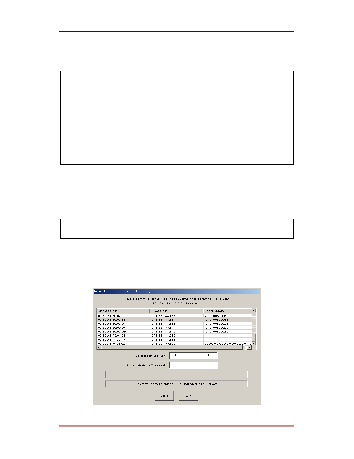
#5.2. Upgrade firmware with upgrading program
(1) Open ‘MS Dos’ window and practice a command <c:\arp –d>.
WEBGATE Inc.
2003. 06. 30 (v 1.4)
59
Page 60
i-Rec B104 Appendix
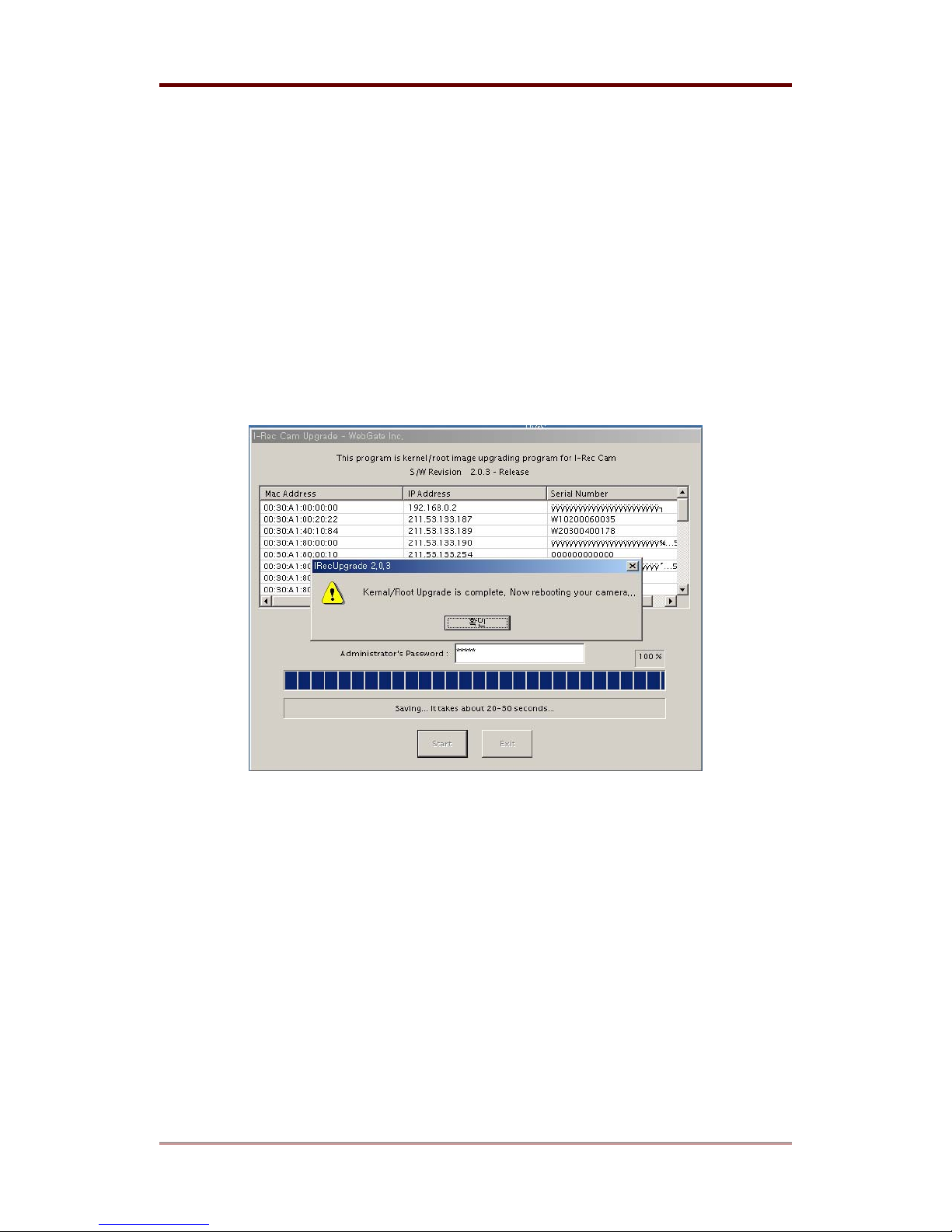
(2) Practice upgrading program and select i-Rec B104 that you are going to update by clicking
on IP address or MAC address in the list. When an IP address appears under ‘Selected IP
address’, key in the administrator’s password in the blank of ‘Administrator’s password’. Then
click ‘Start’ button.
(3) If you click ‘Starting Upgrade’ button, the process will be operated automatically.
Then wait until a ‘Kernel/Root Upgrade is complete. Now rebooting you Camera…’ message
appears. Be cautious not to disconnect network or power until the process is completed.
Otherwise, the i-Rec B104 can be damaged seriously.
(4) After updating process is completed, it is recommended to reboot i-Rec B104 to make it
operate properly.
(5) If you have another i-Rec B104 to upgrade, follow the same process from (1) to (4). If not,
quit the program by clicking ‘Exit’ button.
60
2003. 06. 30 (v 1.4)
WEBGATE Inc.
Page 61

Appendix i-Rec B104
#6. Using CD-ROM
Within the supplied CD-ROM DISC, there are “i-Rec B104 User’s Guide” and several programs
for using i-Rec B104.
Contents of CD- ROM
CamViewerII x.x.x.exe : i-Rec Setup program
ar510enu.exe : Acrobat reader program
i-Rec B104 Installation Guide v1.4.PDF : i-Rec B104 Installation Guide
CamViewer II User's Guide v1.4.PDF : CamViewer II User’s Guide
Preparatory step
To read manuals within CD-ROM DISC, adobe acrobat 5.0 or above should be installed in
client’s PC.
<Note>
If acrobat reader is not installed within client’s PC, use the acrobat reader program of CD-
ROM.
Reading manuals within CD-ROM
Follow the steps to read manuals
(1) Insert the supplied CD-ROM into CD-ROM drive of PC.
(2) Open manuals of PDF file.
WEBGATE Inc.
2003. 06. 30 (v 1.4)
61
Page 62

i-Rec B104 Appendix
#7. Specifications
General
CPU
32bit RISC Embedded Processor
FLASH MEMORY
MAIN MEMORY
OS
VIDEO CHANNEL
STORAGE
Compression
ALGORITHM
RESOLUTION
IMAGE COMPRESSION
RATE
FRAME RATE
IMAGE TRANSFER RATE
8MB
16MB
Embedded Linux
NTSC or PAL video format are supported
4Ch. video input
Internal 3.5” IDE HDD 1EA
Wavelet
720x486, 720x243, 360x243, 180x121, 90x60 (NTSC)
720x576, 720x288, 360x288, 180x144, 90x72 (PAL)
10:1 ~200:1
Max up to 30fps
Max. 30fps (NTSC, on 360x243)
25fps (PAL, on 360x288)
Network
BROWSER
PROTOCOL
CONNECTOR
MANAGEMENT
& S/W UPGRADE
SECURITY
62
CamViewer II (included)
(PC based MS windows 98/Me/2000/NT is required)
TCP/IP, ARP, ICMP, DHCP, PPPoE
10Base-T Ethernet (RJ-45)
IP assigning is available through ARP/RARP protocols
Firmware upgrade through specific program
Password (Based User Authentication)
IP-filtering (Secure Mode)
Image Encryption
2003. 06. 30 (v 1.4)
WEBGATE Inc.
Page 63

Appendix i-Rec B104
Environments
OPE R AT ION TEMP E RATURE
5°C ~ +45°C
STORAGE TEMPERATURE
OPERATION HUMIDITY
STORAGE HUMIDITY
Additional function & I/O
ADDITIONAL FUNCTION
IMAGE ROTATION
PTZ CONTROL
DIGITAL OUTPUT
SENSOR INPUT
Others
POWER
(SUPPLIED ADAPTOR)
CONSUMPTION ELECTRICITY
-25°C ~ +55°C
30% ~ 80% R.H (free of condensation)
93% R.H and less (free of condensation)
Motion detection
Image quality Control (10 Levels)
4.5 MB fresh memory for homepage customization
0°, 180°
RS232, RS485, RS422
4Ch, MAX DC or AC (Peak) 250V, 100mA
4Ch, TYPICAL 12mA (in using Dry Contact)
Input: AC 100~240V, 50~60 Hz
Output: DC 12V, 3.5A
MAX. 2.2A (with 1 HDD)
CONSUMPTION VOLTAGE
PC system requirements for CamViewer II
CPU
MEMORY(RAM)
OS
RESOLUTION
NETWORK
WEBGATE Inc.
MAX. 26.4W (with 1 HDD)
Pentium III 400 and above
(Pentium III 800 and above is recommended)
64 MB and above (128 MB and above is recommended)
Windows 98/Me/2000/NT
1024 X 768 and above
10 Base-T LAN or PSTN
2003. 06. 30 (v 1.4)
63
Page 64
i-Rec B104 Appendix
Mechanical
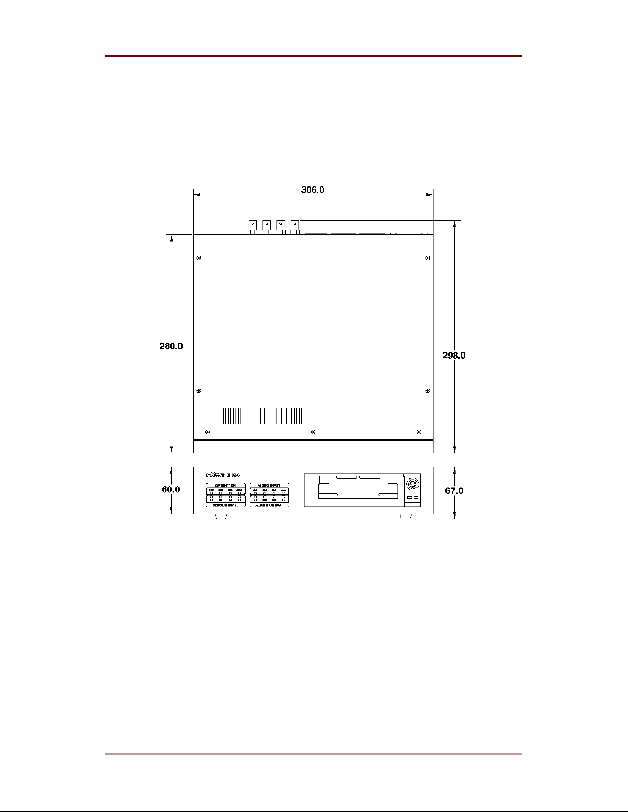
DIMENSION
306mm X 298 mm X 67mm
WEIGHT
3160g (without HDD)
64
2003. 06. 30 (v 1.4)
WEBGATE Inc.
Page 65

WEBGATE Inc.
6F, Hanlim Venture Town Bldg., 689-6, Geumjeong-dong, Gunpo-
si, Gyeonggi-do, Korea (435-862)
Tel : (82-31) 428-9300
Fax : (82-31) 428-3955
www.webgateinc.com
WEBGATE Inc. USA
465 Halstead St. Suite 110, Pasadena, California 91107, USA
Tel : (626) 351-6500
Fax : (626) 351-3660
 Loading...