

Page 1

ENGLISH
1
HD-CCTV DVR
Quick Guide
(EN Rev 1.7)
Hybrid DVR Series
Page 2
ENGLISH
2
Components
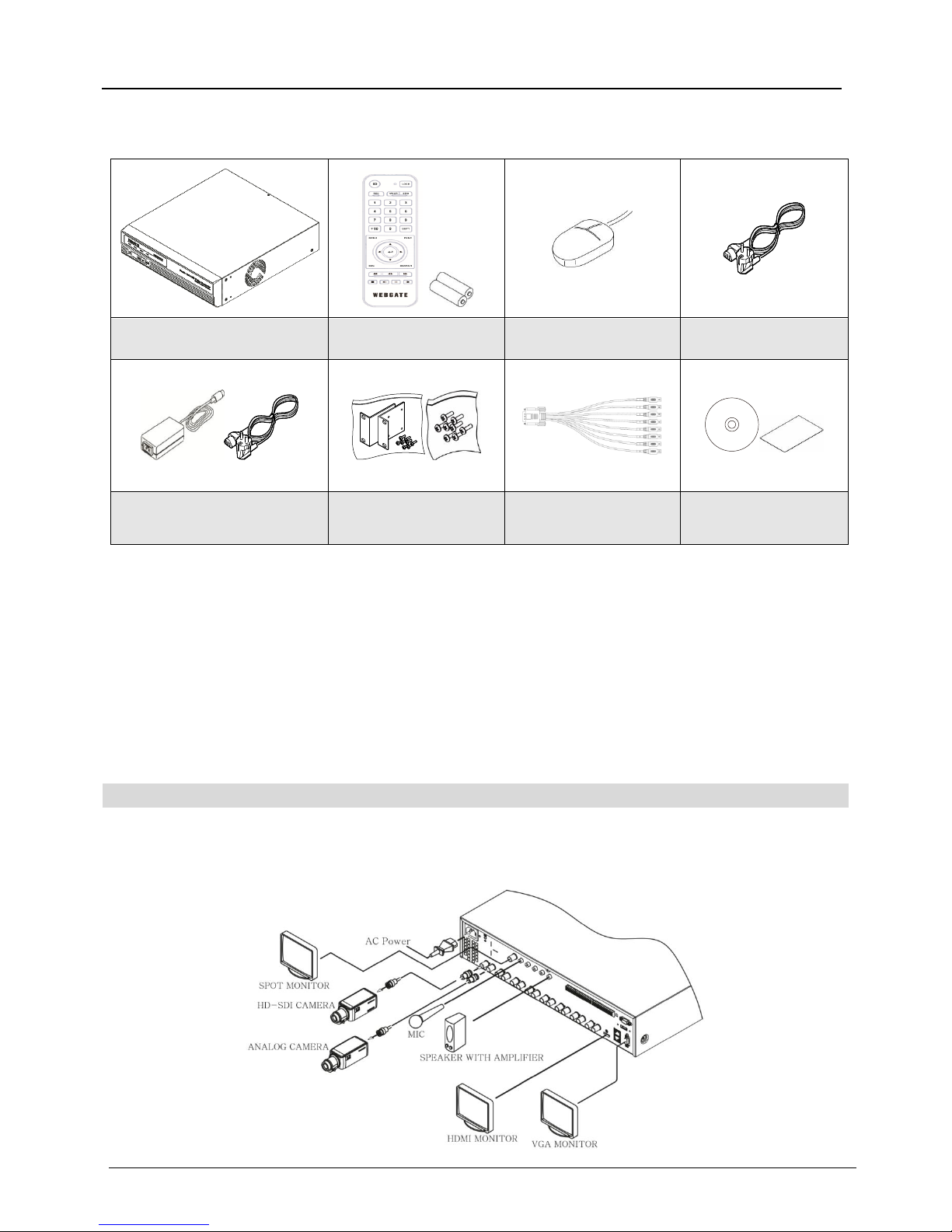
Please check the below to make sure you have every component.
DVR
Remote Control & Batteries
Mouse
power cord
PoC Adaptor *
Rack bracket(optional) *
screw
SD video input extension
cable (*)
SW & Manual CD
Quick guide
* Varies between different models
Before using the product,
Please read the below carefully before using this product.
Don’t use the product outdoors.
Don’t spill water or liquid on connecting part of the product
Don’t place heavy objects or damage the product.
Do not pull out the power plug forcibly.
Do not disassemble the product by yourself.
Don’t use in excess of stated power I/O range.
Use a certified power cord only.
Use ground power plug.
A-class Equipment (Broadcasting Communication Equipment for Industrial use only)
Users should understand this is A-class broadcasting communication equipment for industrial use only and
must not be used for home use.
Connecting different components
Page 3
ENGLISH
3
HDMI Monitor connection
1920X1080p resolution is suppoeted. Please check if monitor can support this resolution before connection.
DVR’s video output : 1920 x 1080p
<Warning>
Use of HDMI certified cable is recommended when connecting to a HDMI Monitor.
VGA Monitor connection
800X600, 1024X768, 1280X1024, 1920X1080 resolution is suppoeted. Please check if monitor can support this
resolution before connection. (4ch models supports only 1920 x 1080 resolution)
VGA output resolution change in the menu
[FUNC menu - tool – VGA resolution] click then select preferable resolution and reboot DVR.
VGA output resolution change by remote control
Press [FUNC-4-2-3-1-4-X-FUNC-MULTI] key in order to change VGA resolution.(based on X value)
X : 1 800x600
X : 2 1024x768
X : 3 1280x1024
X : 4 1920x1280
Connecting to a camera
Please connect HD-SDI(1080P/720P), AHD* (1080P/720P), EX-SDI (1080P/720P), 960H, NTSC/PAL camera using
the recommended cable
* Adopted differently based on product specification.
<Note>
PoC models need additional “SD input video extension cable” in case 960H, NTSC/PAL type cameras are
connected and viewed.
Recommended Cables
* Depends on manufacturer and models.
<Warning>
Transmission distance will be affected by cable types and installation site environment
Transmission distance of cables shows differences based on the attenuation factor at 750MHz.
(dB/100m < 25dB is recommended)
Foamed or high-foamed trishield cable is recommended.
Coaxial cable and BNC connector must have 75Ω impedance.
Careful to cable deformation due to high pressure over the cable.
Don’t pull the cable with too much force.
During the arrangement of the coaxial cables at the rear of the rack, if tied too tightly, inside/outside
insulator of cable could be deformed, so tie it loosely within cable’s curvature range.
Cable Category
HD-SDI transmit
distance(*)
EX-SDI transmit
distance(*)
Applications
5C2V
about 90M
about 150M
Analog cable
4C-FB(T), 4C-HFB(T),
RG59
about 140M
about 280M
High-foamed cable (Double or
Trishield recommended)
5C-FB(T), 5C-HFB, L6CHD, RG6
about 180M
about 360M
Cable for HD-SDI
5C-HFBT
about 200M
about 400M ~ 500M
Cable for HD-SDI
Page 4
ENGLISH
4
HDD registration and format
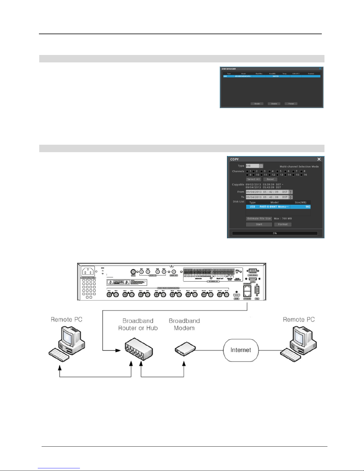
If DVR is powered after HDD installation, it shows “Disk manager”
automatically. (It takes approx. 1minutes after power)
If it doesn’t run, please check the connectivity of HDD
(1) Select a HDD among listed HDDs. Activate the HDD and
execute format.
(2) Check “YES” for the fomatted HDD..
<
warning
>
Please call Webgate or Webgate dealers for HDD compatibility
Copy
In case backup media is well connected, click [Copy] button in FUNC
menu and back media is auto detected.
Process of Copy
Inserting USB disk to DVR’s USD port Select “EXE” as type
Select the channels to copy Decide the period to copy Select
USB disk at Disk List Click Start
Connecting to Network
menu system disk
copy
Page 5
ENGLISH
5
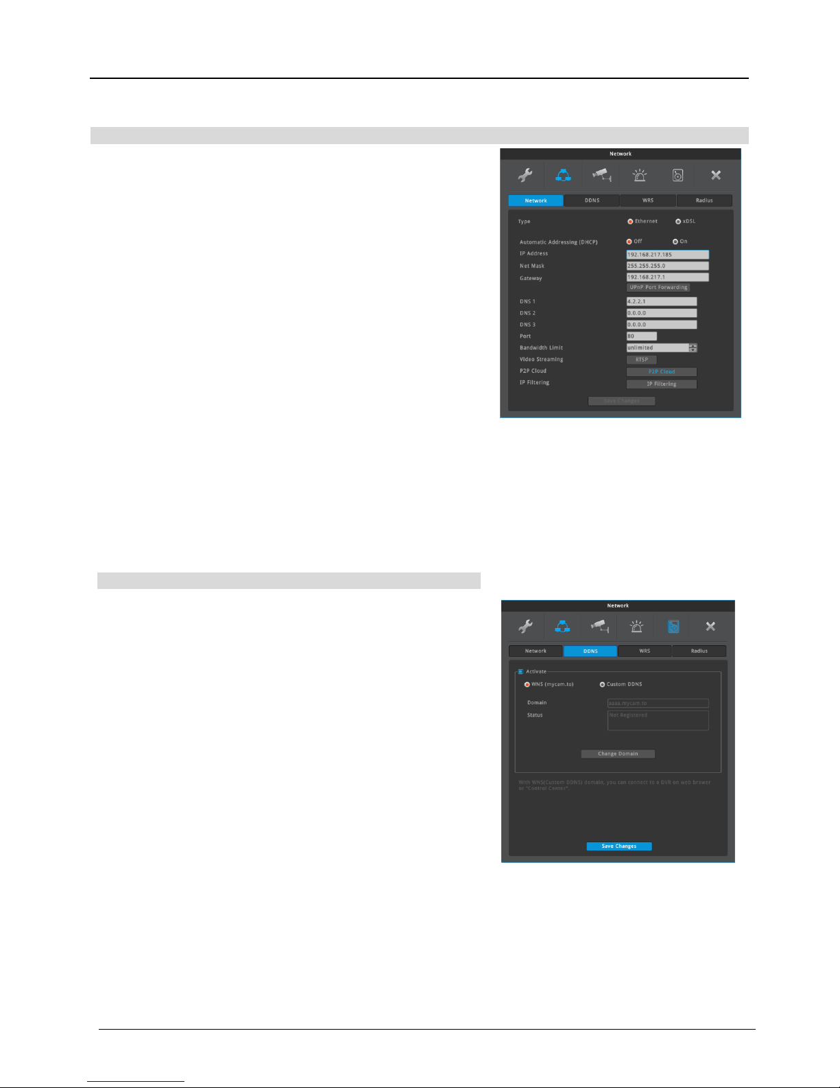
Network settings
IP Address
IP address is used for the communication between DVR and
Control Center, and it is used for Webviewer to connect DVR.
Also Netmask, Gateway addresses given fromt the network
administrator should be properly configured. (When DHCP is
enabled, this item will be disabled)
Net Mask
Net Mask defines the communication range of IP address. This
information should be given from the network administrator.
(When DHCP is enabled, this item will be disabled)
Gateway
DVR should have proper Gateway address to communicate with
external network. This information should be given from the
network administrator. (When DHCP is enabled, this item will be
disabled)
DNS
DVR should have proper DNS address to use various network
services such as WRS, NTP, e-mail and so on. Please ask this
information to network administrator. (When DHCP is enabled,
this item will be disabled)
DDNS
User can give a domain name to a DVR by using WEBGATE’s
DDNS service, WNS(Webgate Naming Service).
DDNS setting at a DVR
1. Change DVR’s port which is not in use (e.g. 8000)
2. Configure router’s port forwarding setting. (i.e. port 8000
should be connected to DVR)
3. Activate DDNS(WNS) at DVR menu
4. Enter domain to use then click on”change domain”.(Ex: test)
5. If the entered domain name is available, DVR shows “Success”.
If the domain name is occupied by another user, DVR shows
“Unavailable domain”.
6. If you can connect a DVR by using assigned domain name, it
means DDNS setting is properly completed.
(e.g. http://test.mycam.to:8000)
<Note>
It takes about 10 min to be connected after domain created.
Menu Network DDNS
DDNS setting at DVR
menu network network Ethernet
Page 6
ENGLISH
6
Record Configuration
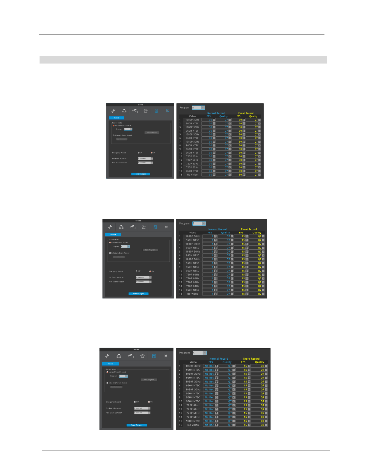
Continuous Recording - The maximum recording performance for Normal and Event recording
1. Menu > Record > Record > Continuous Record > Program A > Program Edit
2. Select Program “A” and set all channels as Normal Record “FPS 30, Quality 7”, Event Record “FPS 30, Quality
7”
(Recording performance may be different according to DVR models)
Long-term Recording - The minimum recording performance for Normal recording
1. Menu > Record > Record > Continuous Record > Program B > Program Edit
2. Select Program “B” and set all channels as Normal Record “FPS 1, Quality 7”, Event Record “FPS 15, Quality
7”
Maxium Long-term Recording - Recording only for event
1. Menu > Record > Record > Continuous Record > Program C > Program Edit
2. Menu > Record > Record > Pre Event Duration 5sec > Post Event Duration 5sec > Program Edit
3. Select Program “C” and set all channels as Normal Record “FPS 0, Quality 7”, Event Record “FPS 15, Quality
7”
Menu Record Program
Page 7
ENGLISH
7
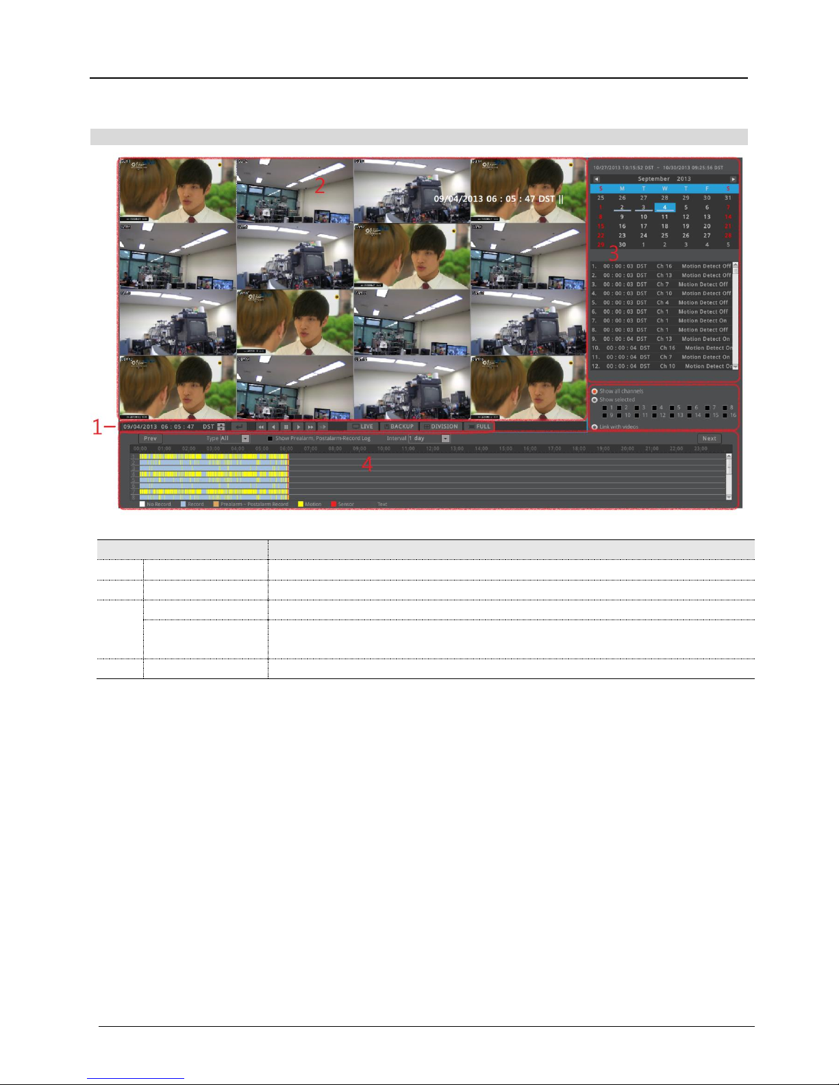
Playback
name
function description
1
Playback button
Use buttons to control the playback.
2
screen
Displays the playback videos.
3
log viewer
Displays the log seen on timeline
Calendar/time
search
Select a date on the calendar to view the data of the date.
4
timeline
Displays the info of the unit and search the playback sections.
Search
Page 8
ENGLISH
8
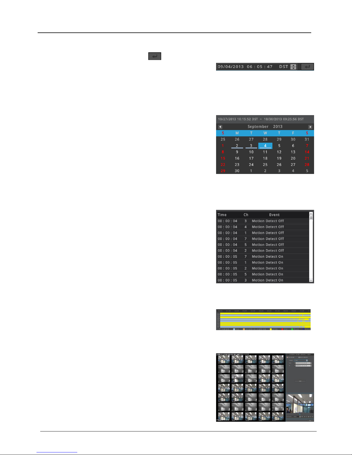
Time search
If the user enter a date and time and click , DVR’s playback
time moves to that time.
Calendar search
When calendar search is run, it marks the dates on which there were
recordings.
Select a date from calendar you want to search, and it moves to
that date.
Event search
Event information on timeline(All, Motion, Sensor, Text, None) will
be shown on log viewer. If the user select one of the list, DVR’s
playback time moves to the event time.
Timeline search
If the user clicks a position on the timeline, DVR’s playback time
moves to that time.
Thumbnail Search
Thumbnail search will show 35 different thumbnail image on
detected images by time interval or motion. Click on selected image
for playback or copy.
• Time interval : 35ea thumbnail images are displayed by searching
image between entered start and end time.
• Motion detection : 35ea thumbnail images are displayed by
searching image on the motion between entered start and end
time.
Page 9
ENGLISH
9
Remote monitoring & control
Users can connect DVRs, control and monitor it remotely by using Control Center (WEBGATE’s CMS program)
Installation of Control Center
Execute “Control Center Setup vx.x.x.exe” to install the Control Center.
Start of Control Center
After installation is completed, click “Control Center Monitor” icon and execute it.
(ID : admin / Password : admin)
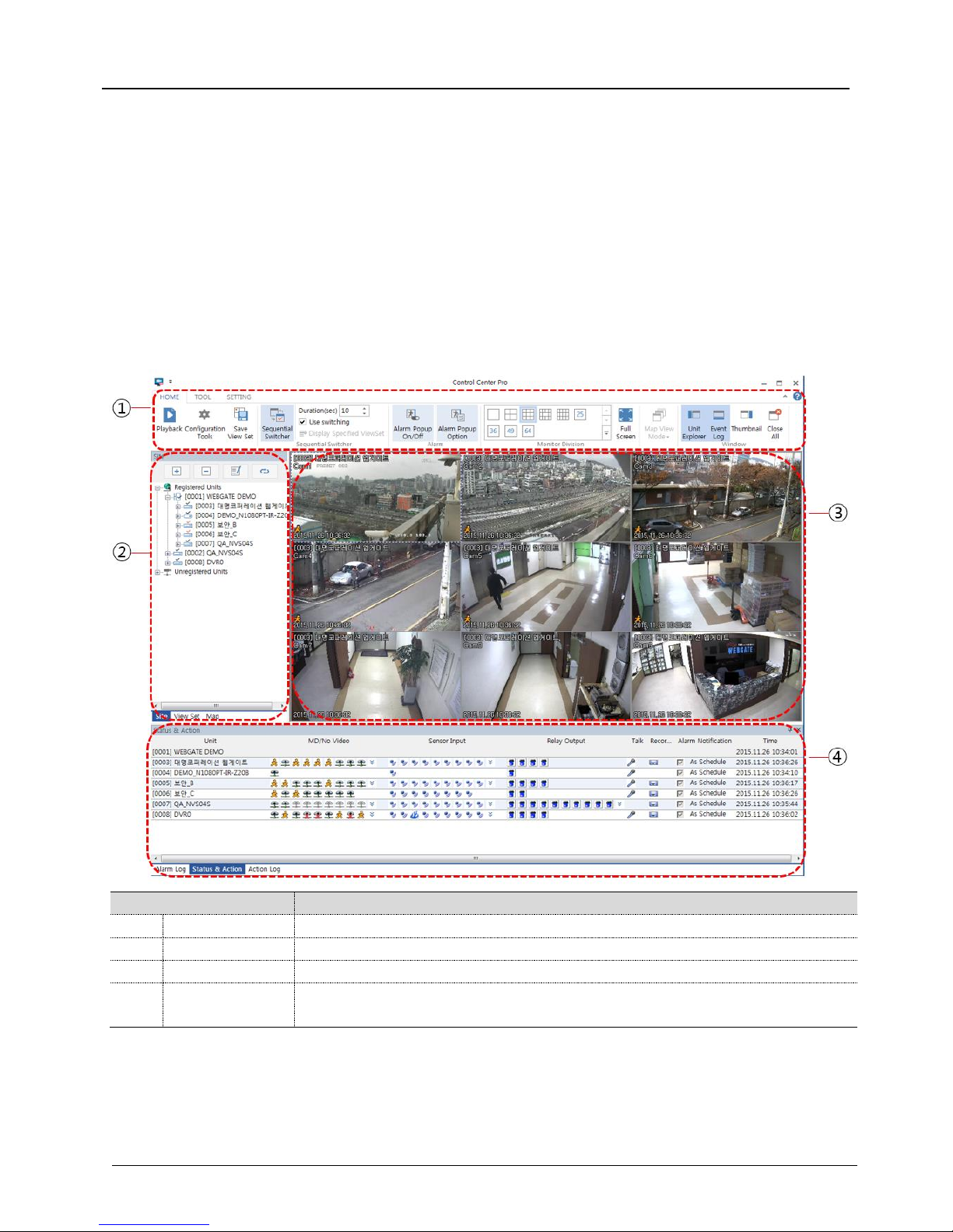
Screen configuration of Control Center
Item
Description
1
Menu/Toolbar
This is menu and function button used in program
2
Unit list window
This indicates unit/viewset/map registered in program. User can click on the list to show image
3
Image window
This indicates live monitoring image
4
Status & Action
window
This indicates status of unit, event information and alarm log
Page 10
ENGLISH
10
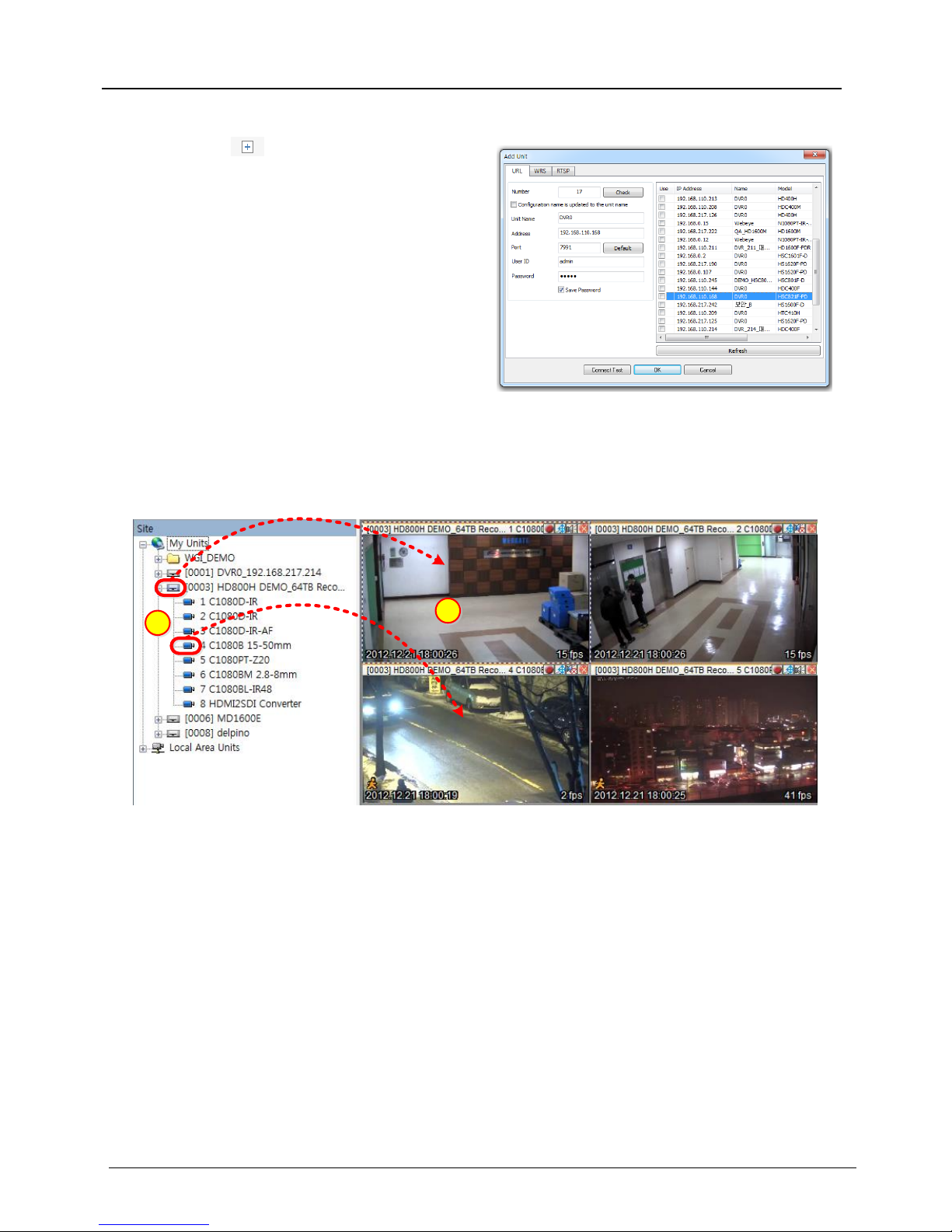
Add Unit
Click [Add] icon on the toolbar or execute [Add
Unit] by clicking mouse right button at “My Units”.
1) Select “URL/IP Adress”
2) Enter proper IP address and Port, then click [Find]
button. If the DVR is located inside local network,
you can easily find the DVR by clicking [Auto
Detect] button.
3) Check whether the unit’s information is properly
displayed.
4) Enter DVR’s ID and pasword, then click [OK].
5) DVR will be listed on the unit list of “My Units”.
(DVR’ Default ID/Password is admin/12345)
DVR’s Live display
If you click a unit’s icon in the “My Units”, you can get live monitoring display. Split-screen will be displayed to
show all channels of the unit.
2
1
All channel display at the same time
① If you click a unit’s icon, all channels' video will be displayed on the split-screen.
Display a specific one channel
① If you drag a camera icon and drop it to one of split-screen, video from the camera will be displayed on the
screen.
Page 11
ENGLISH
11
Port Forwarding & P2P Cloud
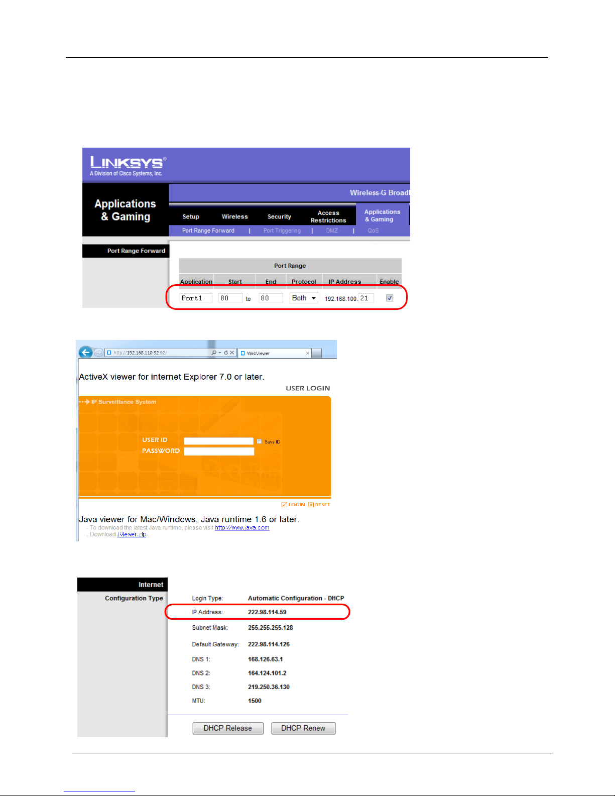
Manual port forwarding
(1) Connect to a router by default IP address.
(2) Go to “Port range forward” setup page.
(3) Set DVR IP address & Port of DVR connected to the router then check ‘Enable’ and save.
(4) Connect to IP and Port number of DVR which are assigned from PC to router.There will be Webviewer
login page once DVR connection is successful. (DVR default port : 80)
(5) Check the router's internet address (Public IP address) to access to the DVR from external network.
Page 12
ENGLISH
12
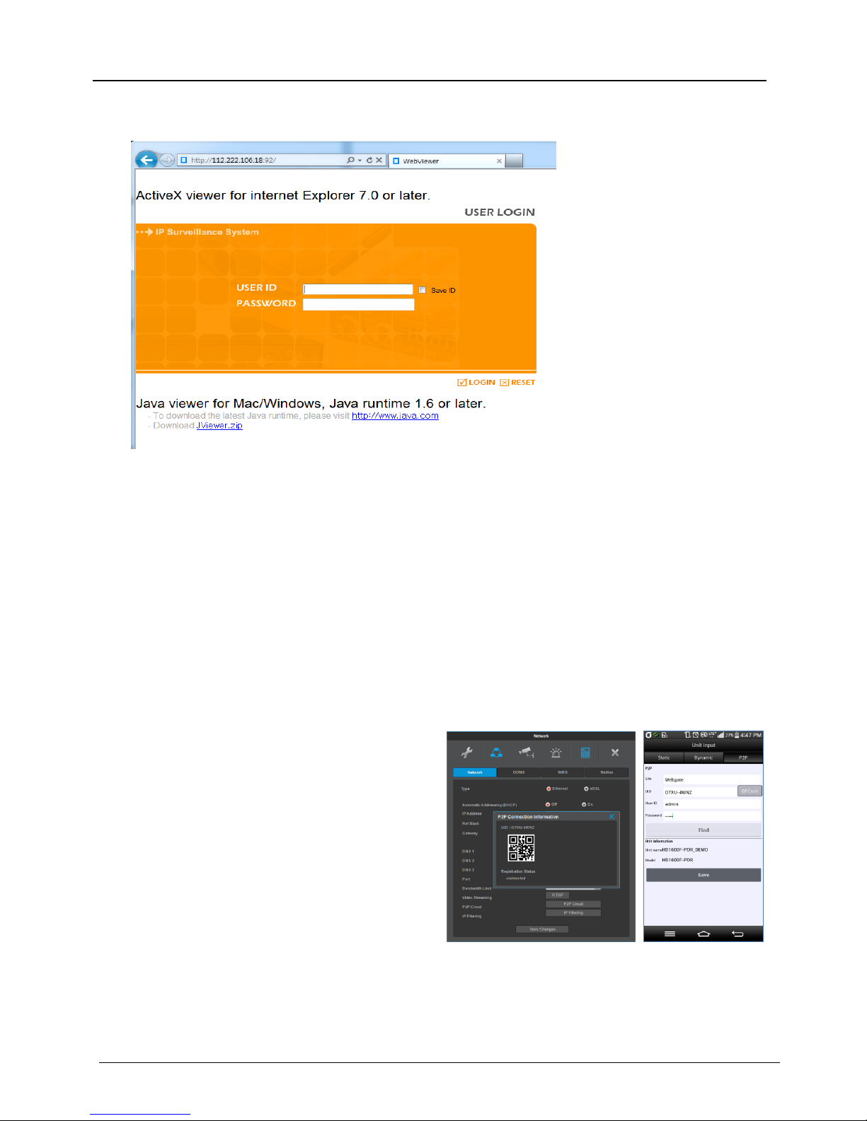
(6) Connect to external internet IP address of router and DVR’s setup port. If DVR connection is
successful, you may see Webviewer’s login page of DVR.
(7) Enter ID and Password of DVR의 to see monitoring page in which live image of DVR is displayed.
UPnP port forwarding
When using Internet Sharing device(Router) which supports UPnP, this function will let users to have an easy
access to many DVRs that are connected to the internet sharing device.
(1) Set DHCP ON for DVR(A) and DVR(B).
(2) Connect a DVR to an Internet Sharing Device and confirm that a public IP address is allocated.
(3) Set 81 to DVR(A) and 82 to DVR(B) as DVR port number.
(4) Configure UPnP function of Internet Sharing Device as “ON”.
(5) Configure UPnP Port Forwarding function of DVR as “ON”.
(6) Confirm Port Forwarding Status message is changed from “Not Available” to “Port Mapping is OK”.
(7) If a user accesses to Internet Sharing Device using port 81, it connects to DVR(A), and if accessed
using port 82, it connects to DVR(B).
P2P Cloud *
Users can easily connect DVRs through Mobile
application, WebEye, and can perform monitoring.
(1) Execute WebEye, click Add(+) button and select
P2P tab.
(2) Enter a Unit name and the UID. User can directly
enter the UID from the UID sticker sticking on DVR
cover. Alternatively, user can find the UID by clicking
P2P cloud button at DVR menu > Network, or user
may take a picture of QR code.
(3) Enter the DVR password first. Then clicking the
Find button will show DVR name and model name.
(4) Save the setting and click the registered unit in
order to see the video
* Varies between different models
Page 13

ENGLISH
13
The World’s first certified by
HDcctv Alliance
Premium to your HD-CCTV
W E B G A T E
WEBGATE Div, Daemyung Corporation Co., Ltd.
6F,Hanlim Venture Town B/D, 284, Gongdan-ro, Gunpo-si, Gyeonggi-do, Korea(15809)
Tel +82. 31. 428. 9383
Fax +82. 31. 455. 3955
www.webgateinc.com
 Loading...