

Page 1
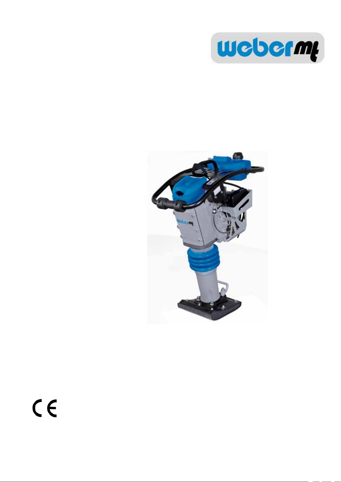
Operating and
Maintenance Manual
SRV 660
Robin-Subaru EH 12-2
Weber Maschinentechnik GmbH
Im Boden 5 - 8 , 10
D-57334 Bad Laasphe-Rückershausen / Germany
Tel.: + 49 (0) 27 54 / 398 0
Fax: + 49 (0) 27 54 / 398 101
0410/englisch/Übersetzung der Original-Betriebsanleitung
SRV 660 1
E-Mail: [email protected]
Web: www.webermt.de
Page 2

2 SRV 660
Page 3

Table of contents
Introduction 4
Safety guidelines 5
Graphic presentation 8
Device description 9
Technical data 10
Activities prior to starting work 12
Starting 13
Tamping 14
Shutting down 14
Maintenance overview 15
Maintenance work 16
Operating uids and ll levels 19
Troubleshooting 19
Measures to be taken if stored for long periods 20
Contact addresses 23
SRV 660 3
Page 4

Introduction
This operating and maintenance manual is designed to facilitate familiarization with your tamper,
and enable you to maintain the tamper and use it in accordance with the proper application
possibilities.
When complying with the instructions in the operating and maintenance manual you help avoid
hazards, reduce repair and downtime costs, and increase the reliability and service life of your
tamper.
This operating and maintenance manual must always be available at the implementation site of
the tamper.
If needed you can obtain additional information from your authorized WEBER dealer, or you can
obtain information from one of the contact addresses on the last page.
You can obtain information on the assembled Robin-Subaru petrol engine and nd a spare-part list
for it at www.robin-europe.de
The valid conformity declaration is enclosed with every machine delivery.
4 SRV 660
Page 5

Safety guidelines
General
All safety instructions must be read and complied with, non-compliance results in
- Danger to life and limb of the user
- Impairments to the machine or other property.
In addition to the operating manual the binding accident prevention guidelines in the country where
the compactor is used must be complied with.
Proper use
The tamper should only be used in technically faultless condition, as intended, in a safety-conscious
and hazard-conscious manner, in compliance with the instructions in the operating manual.
Malfunctions that impair safety must be eliminated without delay.
The SRV 660 tamper is designed exclusively for compacting
- Sand
- Gravel
- Crushed rock
- Semi-cohesive mixed material
Any other use of the tamper is considered to be improper use for which the owner shall be
exclusively responsible. All liability is rejected if damage occurs due to non-compliance with this
provision. This risk is borne solely by the user.
Easily foreseeable misuse
Any use for which the machine is not intended.
Operating
Tampers should only be operated by suitable personnel at least 18 years of age, Operators must be
instructed in how to guide the tamper by the owner or by owner’s assigned personnel.
The machine operator must comply with trafc regulations. If instructions that affect safety are given
by third persons, then the operator must be authorized to reject these instructions.
Unauthorized persons are forbidden from being in the area of the soil compactor during the
compacting process.
Protective equipment
This machine is capable of exceeding the permissible sound level of 80 dB(A). The owner might also
face additional dangers when using the machine. Precautionary action must, therefore, be taken.
Protective equipment includes:
Ear protection
Hard hat
Safety shoes
Protective gloves
SRV 660 5
Page 6

Operation
Prior to starting work the owner of the tamper must be familiar with the work environment. The work
environment includes obstacles in the work and trafc area, the bearing capacity of the ground, as
well as the necessary safeguarding of the construction site in the area adjacent to public trafc; and it
includes compliance with trafc regulations.
The tamper should only be operated when the protective xtures are mounted. The protective xtures
must all be in functional condition.
At least once per shift the tamper must be checked for apparent defects. If there are apparent defects
then operation of the tamper must be stopped immediately and the responsible person must be
informed. Prior to restarting, tamper malfunctions that have occurred must be corrected.
Operation under difcult conditions
Never inhale the exhaust gas; it contains carbon monoxide, a colorless and odorless gas that is
extremely hazardous, which if inhaled even briey can cause unconsciousness and death.
Never operate the engines in enclosed areas or in areas that are poorly ventilated (tunnels, caves,
etc.) Exercise particular caution when operating the engine in the vicinity of people and livestock.
Prior to maintenance and repair work
Only use original Weber spare parts to ensure reliable and safe operation for maintenance or repair
work.
Adjusting tasks, maintenance tasks, and inspection tasks must be executed on schedule as specied
in this operating and maintenance manual. These activities should only be executed by instructed
personnel.
For repair, maintenance, or inspection work the engine of the tamper must be safeguarded against
unintentional starting.
All pressurized lines, particularly hydraulic lines and lines of the injection system of the drive motor
must be depressurized before performing maintenance or repair tasks.
For maintenance and repair tasks the tamper must be placed on a level and stable substrate and
must be secured from rolling off or tipping over.
Heavy components and subassemblies must be secured on hoisting machines with adequate bearing
capacity when they are replaced. Ensure that no hazard exists related to the raised components or
subassemblies.
Do not position yourself or work under suspended loads.
If lubricating oils and fuel come into contact with skin, they can cause skin cancer. Upon contact
with the skin, clean affected skin with suitable cleaning agent without delay.
6 SRV 660
Page 7

Inspection
Tampers must be inspected in accordance with appropriate implementation conditions and operating
conditions, as needed; however an inspection to ensure operationally safe status must be performed
by an expert at least once a year. The results of the inspection must be recorded in writing and must
be stored at least until the next inspection.
Cleaning work
Prior to cleaning the tamper with a high-pressure cleaner, protect all accessible energized switches,
cable connections, etc. against water penetration by masking them off.
Cleaning tasks should only be executed in areas that are suitable and approved for this purpose (oil
separator).
Disposal
All operating uids and auxiliary materials must be disposed of in an environmentally-compatible
manner, in accordance with country-specic regulations.
Important information for operating and maintenance personnel is marked by pictograms.
Warning against irritants or materials hazardous to health
Warning against a hazardous place
Warning against a suspended load
Wear ear protection
General regulation
Environmental protection
Hard hat
Safety shoes
Protective gloves
SRV 660 7
Page 8
Graphic presentation
2
1
11
3
9
8
4
5
10
6
7
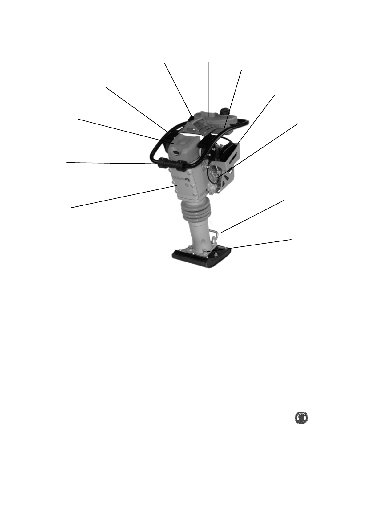
Total overview SRV 660
1 Fuel tank 6 Tamping system
2 Gas lever 7 Tamping foot
3 Hand guide bracket 8 Main lter
4 Engine 9 Sub lter
5 Transport rollers 10 Handle
11
Wear ear protection (Stickers)
8 SRV 660
Page 9

Device description
The series SRV 660 tamper is used for road-building, canal construction, pipe laying and landscaping
compaction tasks.
The tamper is powered by an air-cooled Robin -Subaru-gasoline engine.
The engine is protected by a double lter system consisting of an oversized main air
lter and an additional air lter.
Engine protection by double airlter system, consisting of main lter and sub lter.
Force is transmitted via the centrifugal clutch directly to the tamping system. The compaction work is
performed by the tamping foot.
Operation
Start the Robin-Subaru- gasoline engine with the attached reversing starter.
After starting the stamping system starts to vibrate via the centrifugal clutch which is attached to
the engine. Use the gas lever to adjust engine speed via the xed idle speed and full-throttle speed
lock-in settings. For easier transport the tamper can be pushed onto or into a means of transport.
SRV 660 9
Page 10
Technical data
SRV 660
Weight
Operating weight CECE in kg 75
Dimensions
Overall length in (in mm) 740
Overall width in (in mm) 385
Height (in mm) 1035
Tamping foot width (in mm) 280
Impact rate (/min) 670
Stroke (in mm) 70
Drive
Engine manufacturer Robin-Subaru
Type EH 12-2
Performance at operating speed in accordance with
ISO 3046-1 (kW)
2,3
Combustion process 4-stroke gasoline
Operating speed (1/min)
Fuel
3600
Gasoline
unleaded
SRV 660
Noise emissions in accordance with 2000/14/EC
Sound pressure level L
ascertained in accordance
PA
with EN 500, in dB (A)
Sound power level L
ascertained in accordance with
PA
EN ISO 3744 and EN 500, in dB (A)
98
108
Vibration values
Root-mean-square acceleration value for hand-arm
vibration ascertained in accordance with EN 500 in m/
8,8
s²
In accordance with directive 2006/42/EC,
complying with the vibration values is
the owner‘s responsibility.
10 SRV 660
Page 11

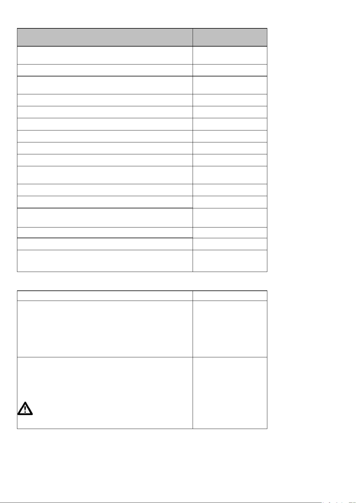
1
2
3 4
5
1Description 2 TYPE
.................................................... ...................................................
3 Serial-Number 4 Year of construction
.................................................... ....................................................
5 Mass 6 Rated power KW
6
SRV 660 11
Page 12
Activities prior to starting work
Transport
When transporting the soil compactor on a vehicle,
secure it with suitable restraints.
Loading with crane
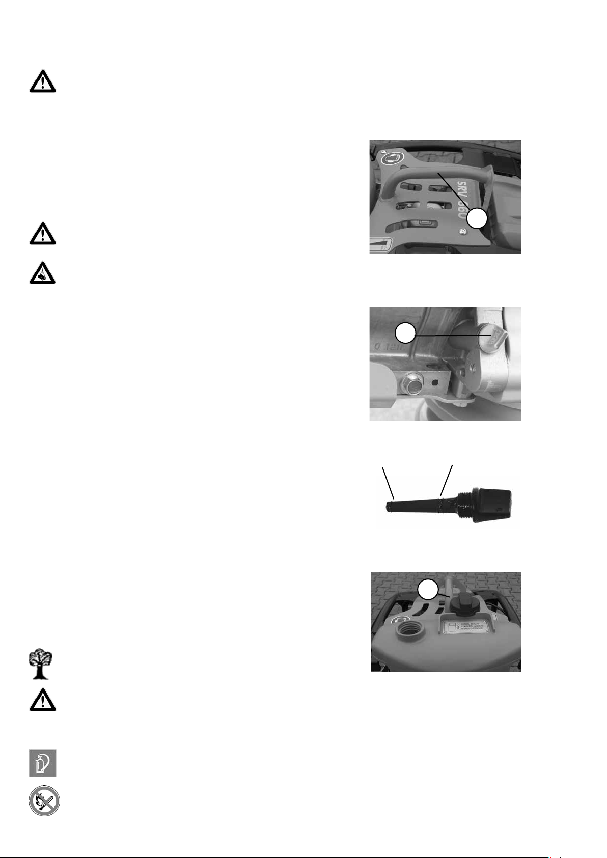
Fit the crane hook into the lifting ring (1) and lift the machine
onto the desired means of transport.
Only use lifting machines with a minimum bearing capacity of 100 kg.
Do not step under suspended loads.
Checking the engine oil level
Pull the oil dip stick (1) out of the crankcase.
The correct oil level is between the min. and max. marks.
Min.
1
1
Max.
Check the fuel level
1
Open the gas cap (1), check the ll level, if necessary top
off to the lower edge of the ller neck with clean fuel in
accordance with the specication.
Carefully wipe up spilled fuel.
If lubricating oils and fuel come into contact with skin,
they can cause skin cancer. Upon contact with the
skin, clean affected skin with suitable cleaning agent
without delay.
For work at the fuel system, have a suitable re-extinguishing agent at the ready.
Fire, naked light, and smoking is forbidden!
12 SRV 660
Page 13
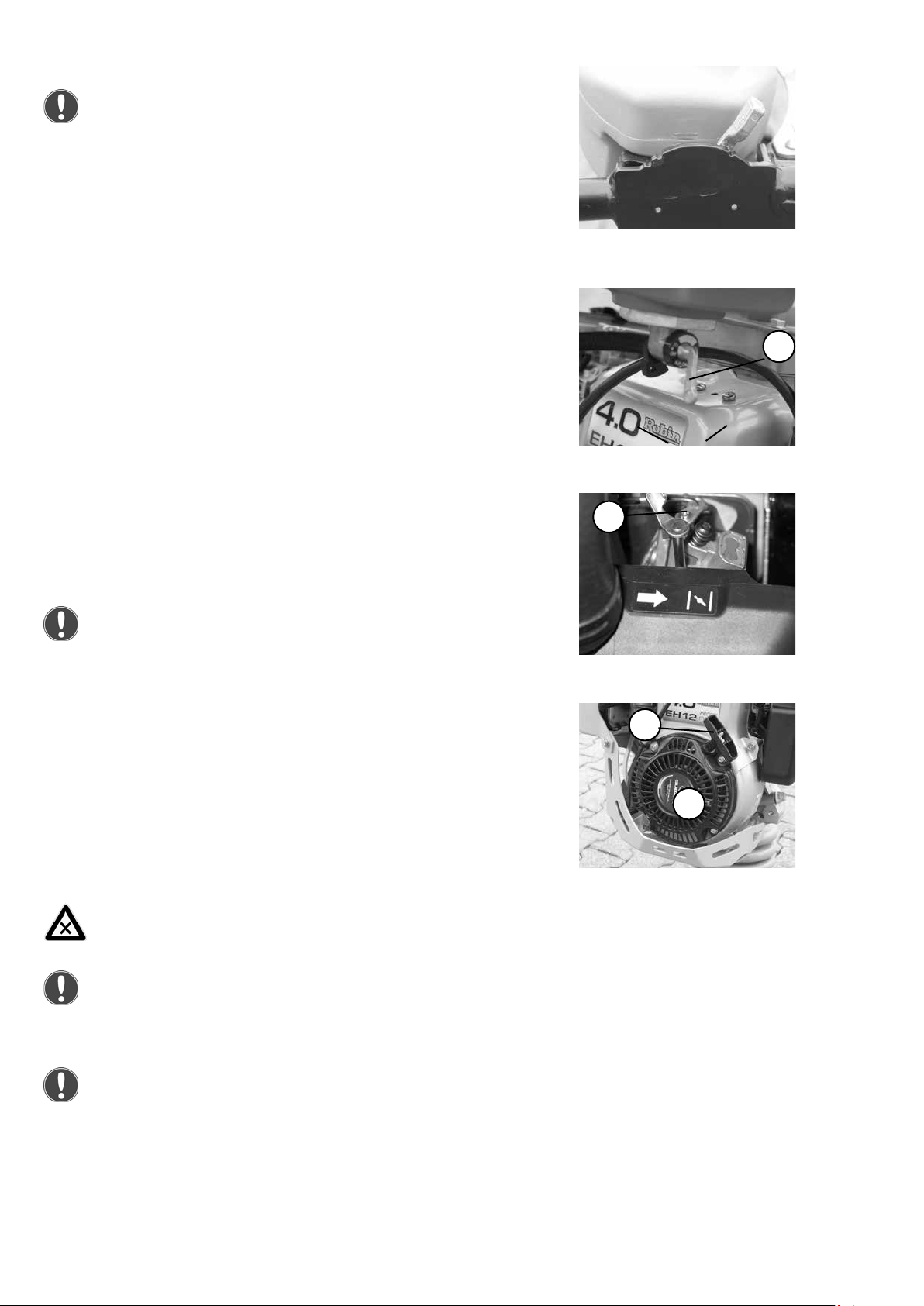
Starting
After horizontal transport: Bring tamper into a vertical
position and wait several minutes until the engine oil
has collected in the lower area of the crankcase.
Bring the gas lever into full-throttle lock-in position.
Open the fuel cock (1).
Push the choke lever (1) to the right (close).
1
After the engine has warmed up, slide the choke lever
(1) to the left (open).
Slowly pull the handle (1) of the reversing starter (2) until
resistance is noticeable.
Allow the handle (1) to glide back into the initial position, and
then forcefully and completely pull it through with both hands.
Allow the engine to warm up for a few minutes.
When starting the soil compactor in closed premises,
always ensure a proper ventilation - danger of poisoning.
1
1
2
In case of ambient temperatures of 5 degrees C below
zero or less, the starting procedure must be carried out
in acoordance with the operation manual of the engine
manufacturer.
Never use starting aid sprays.
SRV 660 13
Page 14
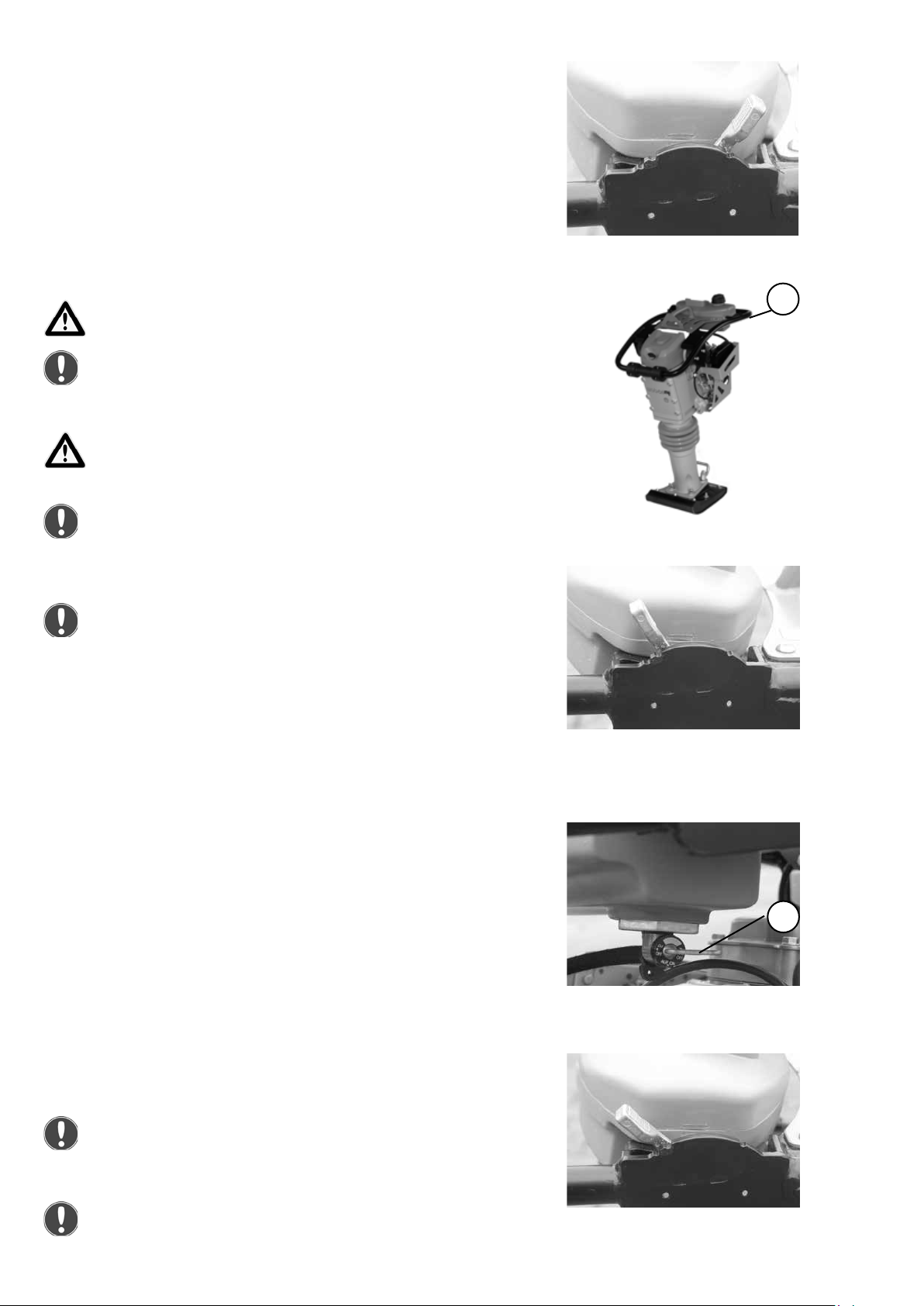
Tamping
Bring the gas lever into full-throttle lock-in position.
Use the hand guidance rod to guide the tamper (1).
Only run machine within reach of the manual guidance
rod.
Compaction work is only allowed at full engine speed.
Otherwise the cetrifugal clutch may slip and cause
increased wear.
At obstructions (walls, pits, etc.), ensure that no one can
be caught between the machine and the obstruction; or
ensure that the machine does not slip into the pit.
Unauthorized persons are forbidden from being in the
area of the soil compactor during the compacting process.
Shutdown
Never stop the engine while it is running at full speed,
but let the engine idle for some minutes.
Bring the gas lever into idle position.
1
Close the fuel cock (1).
1
To shut off the engine push the gas lever back beyond the
idle lock-in setting.
During breaks—even if they are short—the machine
must be shut down.
Parked devices that represent an obstacle must be
safeguarded against conspicuously.
14 SRV 660
Page 15

Maintenance overview
Maintenance interval
After the rst 10
operating hours
Every 50 operating
hours/every 6 months
Every 150 operating
hours
Maintenance
point
Maintenance activity
Engine - Change engine oil
Re-tighten all accessible
threaded connections
Main lter -
Clean air lter insert, check for
damage, replace if necessary
Engine - Change engine oil
- Change the fuel lter
Sub lter -
Clean sub lter, check for
damage, replace if necessary
Every 150 operating
hours/every year
In addition to the aforementioned maintenance work, the engine manufacturer’s regulations must
be complied with.
Work must be carried out using regulation tools and the operating and maintenance manual must
be complied with for all work.
All maintenance work: select a collection vessel that is large enough to prevent oil from spilling onto
the ground. Dispose of waste oil in an environmentally friendly manner (regulation on waste oils).
Dispose of oils, oil-soaked cloths, and parts replaced and smeared with oil in an environmentally
friendly manner.
If lubricating oils and fuel come into contact with skin, they can cause skin cancer. Upon contact
with the skin, clean affected skin with suitable cleaning agent without delay.
If accessible during maintenance, check the condition and stability of all screws.
Tamping system - Change oil
SRV 660 15
Page 16
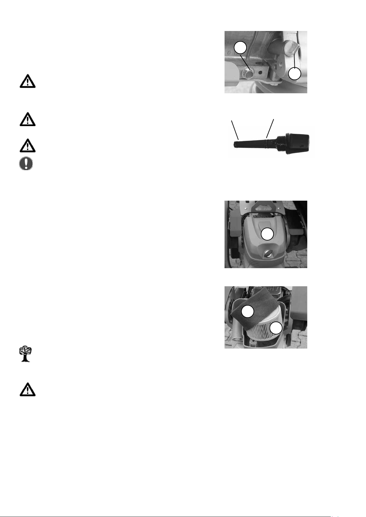
Maintenance work
Change engine oil
Remove the oil dip stick (1).
Open the drain plug (1) of the engine and drain oil.
Only drain engine oil when at operating temperature.
Screw in the oil drain plug (1) with new seal and top off with
oil as specied.
Danger of scalding due to hot oil!
When working in the area of the engine compartment
there is a danger of being burnt!
Check the oil ll level with the oil dip stick again.
Clean/change main lter cartridge
Unscrew the air lter cover (1).
min.
2
1
max.
Remove the air lter insert (1) and the air lter eece (2)
from the air lter enclosure or remove air lter cover.
Clean air lter insert and air lter eece as specied by
the engine manufacturer, if there is damage or or extreme
fouling replace.
Dispose of oils, oil-soaked cloths, and parts replaced and
smeared with oil in an environmentally friendly manner.
If lubricating oils and fuel come into contact with skin,
they can cause skin cancer. Upon contact with the skin,
clean affected skin with suitable cleaning agent without
delay.
1
2
1
16 SRV 660
Page 17
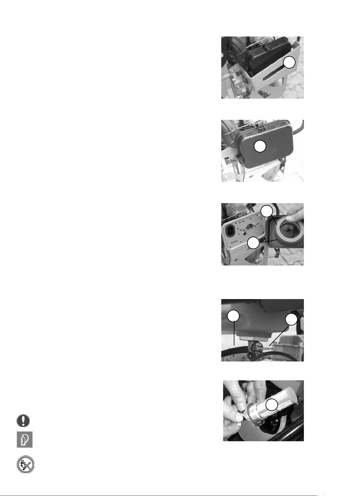
Clean/change sub lter cartridge
Remove protection (1).
Air lter cover (1) remove.
1
1
Remove the air lter insert (1) and the air lter eece (2) from
the air lter enclosure or remove air lter cover.
Clean air lter insert and air lter eece as specied by the
engine manufacturer, if there is damage or or extreme fouling
replace.
Change the fuel lter
Pull the fuel line (1) off of the fuel cock (2).
1
2
1
2
Unscrew the fuel cock, including fuel lter (1) out of the fuel
tank.
Clean the fuel lter
1
Replace fuel lter if damaged.
For work at the fuel system, have a suitable re-extin-
guishing agent at the ready.
Fire, naked light, and smoking is forbidden!
SRV 660 17
Page 18
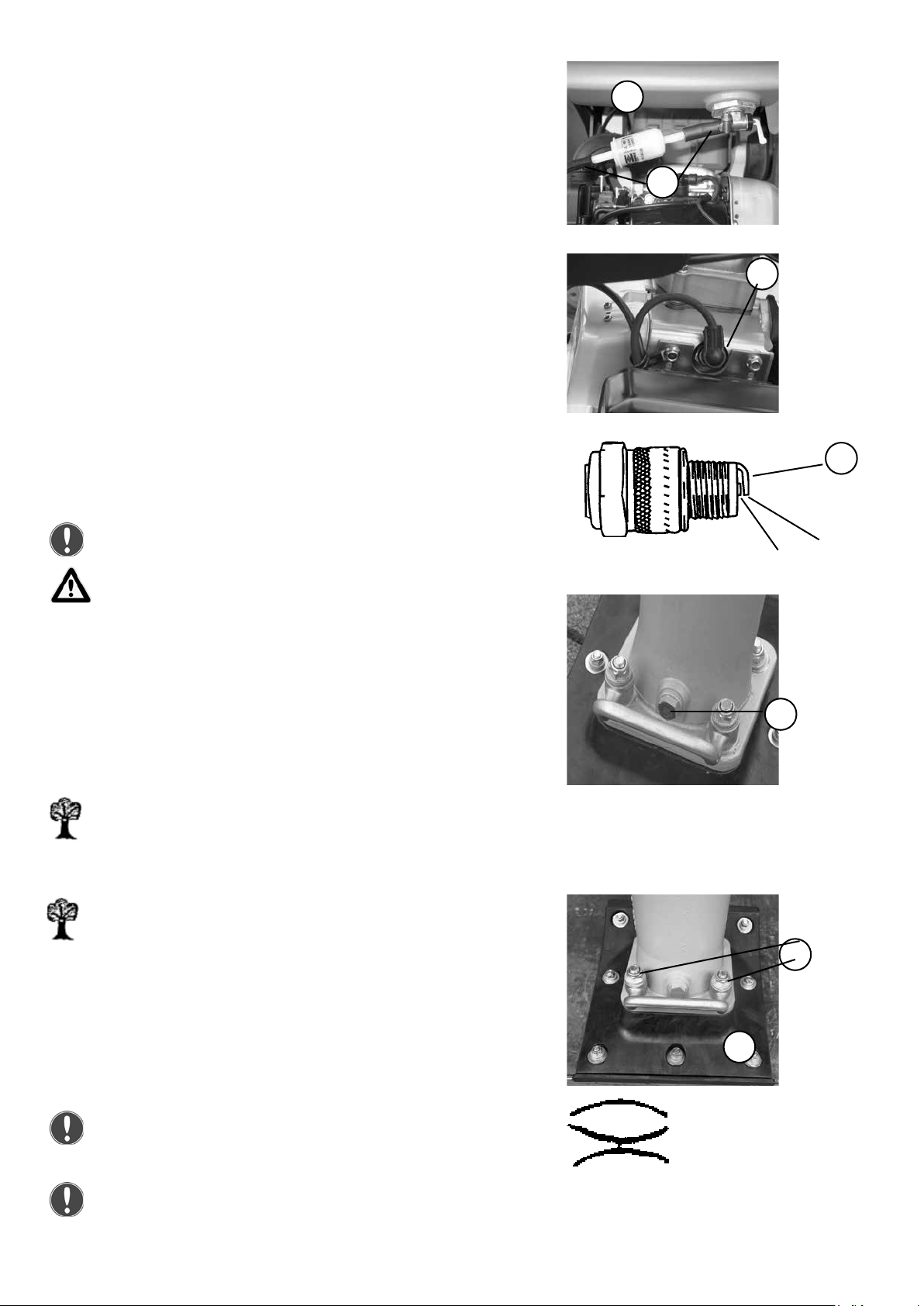
Change the fuel lter
Pull the fuel line (1) off of the fuel lter (2).
Replace fuel lter.
1
2
Adjusting/replacing the spark plug
Pull off the spark plug connector (1) and unscrew spark plug.
Clean the electrode (1) of the spark plug.
Measure the electrode air gap (1), the gab should be 0.6 - 0.7
mm.
Correct the electrode air gap or replace the spark plug if
necessary.
Only use spark plugs with the correct thermal value.
0.6 - 0.7 mm
This work may only be carried out when the engine is cold.
Changing the oil in the tamping system
Unscrew the screw plug (1) from the ll opening.
Tilt the tamper forward slightly and let the old oil drain into a
suitable collection container. Tilt the tamper back and ll oil
in as specied.
Clean the screw plug and screw it into the ll opening.
1
1
1
All maintenance work: select a collection vessel that
is large enough to prevent oil from spilling onto the
ground. Dispose of waste oil in an environmentally
friendly manner (regulation on waste oils).
Dispose of oils, oil-soaked cloths, and parts replaced
and smeared with oil in an environmentally friendly
manner.
Changing the tamping foot
Unscrew the 4 nuts (1).
Lift the tamping foot (2) off of the tamper and attach a new
tamping foot.
When mounting the new tamping foot the nuts (1) must
be tightened with a torque of 35 Nm.
Mount the fastening nuts of the tamping foot using the
plate springs as shown in the adjacent illustration.
18 SRV 660
Mounting
arrangement of the
plate springs
2
1
Page 19

Operating uids and ll levels
Subassembly Operating material
Summer Winter SRV
Quality 660
Engine
Engine oil SAE 10 W 40 0.4 l
Fuel tank
Gasoline Normal unleaded gasoline in accordance with DIN 51607 3,0 l
Tamper lower part Hydraulic oil HVLPD 68 1,0 l
Troubleshooting
Fault Possible cause Remedy
Tamper does not start Operating error
Execute the start process as
prescribed
Lack of fuel Check the fuel level
Air lter fouled Clean/change air lter
Fuel lter fouled Change the fuel lter
Spark plug fouled
Clean, adjust, replace the
spark plug
Oil level too low Top off with oil
Engine runs but it does
not reach full speed
The fuel line is incorrectly
mounted
Check the mounting of the
fuel line
or engine runs Air lter fouled Clean/change air lter
but stops after Fuel lter fouled Change the fuel lter
a short time
Spark plug fouled
Clean, adjust, replace the
spark plug
Fuel cock closed Open fuel cock
Engine runs at full rpm,
tamper does not
tamp or tamps
Centrifugal clutch is
defective
Repair
inadequately
Unclean compaction
pattern
SRV 660 19
Tamping foot is worn Change the tamping foot
Page 20

Measures to be taken if stored for long periods (longer than one month)
- Clean thoroughly
Entire soil compactor
Fuel tank
Engine
- Check watertight
- If there are leaks, correct defect
-
Empty fuel and ll with clean fuel
up to the lower edge of ller neck
Check oil level, if necessary ll to
upper oil-level mark
-
Check air lter, clean, replace if
necessary
Check fuel lter, change if
necessary
All bare parts/accelerator/accelerator
control cable/fastening bolts
If the machine is to be stored for longer than six months, then contact the Weber service organization to discuss additional measures.
- Oil/grease
20 SRV 660
Page 21

SRV 660 21
Page 22

22 SRV 660
Page 23

Weber Maschinentechnik GmbH
For problems, questions and further information refer to one of the following addresses:
in Germany WEBER Maschinentechnik GmbH
Im Boden 5 – 8, 10
57329 Bad Laasphe - Rückershausen
in France WEBER Technologie SARL
14’ rue d’ Arsonval
69680 Chassieu
in Poland WEBER Maschinentechnik
Sp. zo.o.
Ul. Grodziska 7
05-830 Stara Wies
In Tschechien WEBER MT s.r.o.
V Piskovne 2054
278 01 Kralupy nad Vitavou
Telefon
Telefax
E-Mail
Telefon
Telefax
E-Mail
Telefon
Telefax
E-Mail
Telefon
E-Mail
+ 49 (0) 2754 - 398-0
+ 49 (0) 2754 - 398101-switchboard
+ 49 (0) 2754 - 398102- spare parts-
directlinie
+ 33 (0) 472 -791020
+ 33 (0) 472 – 791021
+ 48 (0) 22 - 739 70 - 80
+ 48 (0) 22 - 739 70 - 81
+ 48 (0) 22 - 739 70 – 82
+ 42 (0) 776 222 216
+ 42 (0) 776 222 261
in
USA and
Canada
in South -
America
SRV 660 23
WEBER Maschinentechnik do Brasil
93310-405 Novo Hamburgo /RS
WEBER MT, Inc.
45 Dowd Road
Bangor, ME 04401
Rua João Werno Erhart, 4691
Bairro Rincão
Brasil
Telefon
Telefax
E-Mail
Telefon
Telefax
E-Mail
+ 1(207) - 947 - 4990
+ 1(207) - 947 – 5452
+ 55 (0) 51- 587 3044
+ 55 (0) 51- 587 2271
Page 24

> Vibratory plates
> Vibratory tampers
> Vibratory compactors
> Pavement saws
> Poker vibrators and converters
> Rotary trowels
Weber MASCHINENTECHNIK GmbH
Im Boden
D-57334 Bad Laasphe - Rückershausen
Phone ++27 54 / 398 0 - Fax ++27 54 / 398 101
24 SRV 660
 Loading...