

Page 1
OPERATING AND
MAINTENANCE
INSTRUCTIONS
0307/englisch
CF 2
Robin EX17D
Honda GX160
Weber Maschinentechnik GmbH
P. O. Box 21 53, D-57329 Bad Laasphe-Rückershausen
Phone ++27 54 / 398-0
Telefax (++ 27 54) 3 98-101 (Reception) &
3 98-102 (Spare Parts)
Page 2

2 CF-2
Page 3

CF-2 3
Preface
These operating and maintenance instructions describe the safe operation of the CF-2 soil compactors. Please
read this operation manual and familiarize yourself with all details of your compactor before operating the machine
for the first time. Carefully follow all instructions and always carry out the described operations in the indicated
order.
Please refer to the following page for the General Safety Instructions.
We reserve the right to modifiy our equipment without prior notice.
In chapter 1, the soil compactor is briefly described to provide you with a good overview on the location of the
individual assembly groups and their functions. Chapter 2 describes how to put the compactor into and out of
operation and how to work with the machine.
In chapter 3, you will find a survey on and a description of the required service work. Chapter 4 contains instructions
for trouble shooting by the operator. Chapter 5 describes how to preserve the machine for an extended storage,
e.g. during the winter season.
We placed a great emphasis on a user-friendly lay-out with clear pictorial and textual information. In the text, you
will find figures in brackets which point out to illustrations, whereby the first figure indicates the figure number and
the second one - separated by a dash - indicates the item number on the corresponding illustration.
Example 1: (2/1) means figure 2, item 1
Example 2: (2/3,6) means figure 2, item 3 and item 6
Important information for the operator and service personnel is highlighted by pictograms.
Indicates important information and hints which must be followed by the operator and service personnel.
Indicates working and operating methods requiring in addition the observance of all applicable environment
protection and waste disposal regulations.
Indicates working and operating methods which must be precisely followed in order to prevent the
compactor from being damaged or deteriorated.
Indicates working and operating methods which must be precisely followed in order to avert direct danger
to persons.
For further information, please contact your authorized WEBER distributor or one of the addresses on the last
page.
Page 4

4 CF-2
General Safety Instructions
General
All safety notes (see also explanations of the pictogram meanings in the preface) must be read and observed (any
lack of clarity must be dispelled before the compactor is put into operation), because otherwise the use of the
machine may
* constitute a risk to life and limb of the user
* impair the soil compactor and other valuable property.
In addition to these operating instructions and the mandatory accident prevention regulations in the country of use
and on the operating site, the generally accepted technical standards for a safe and professional work must be
also observed.
Designated Use
Soil compactors are only allowed to be operated in accordance with their designated use, whereby the operating
and maintenance instructions, the generally accepted safety and traffic regulations and the regulations of the
individual countries of use must be followed:
The compactor has been exclusively designed for the compaction of
-sand,
-gravel,
-asphalt,
- dry lean concrete,
- insulating material/perlite
Any other use of the compactor is considered contrary to its designated use. The owner of the compactor bears
the sole responsibility for any misuse of the machine.
Driving Permission
Only trustworthy persons, who are aged at least 18 years, are allowed to handle soil compactors. They must be
properly trained in the operation and maintenance of the compactor by the owner or his authorized representative.
Protective Equipment
When operating the soil compactor described in this operation and maintenance manual, the noise level at the
operator's ear may exceed 90 dB(A). The German noise protection regulations (VBG 121) require the operator
to wear personal ear protectors in case of noise levels of 90 dB(A) and more.
Additionally, a safety helmet and safety shoes belong to the protective equipment.
EC Machinery Directive, prEN500-1, EN292
Page 5

CF-2 5
Tabl e of Contents
Paragr. Title ........................................................ Page
Preface....................................... 3
General Safety Instructions ..... 4
Table of Contents ..................... 5
1Technical Description..............6
1.1 Illustration ............................................ 6
1.2 Machine Description ........................... 7
1.3 Specifications ................................... 8/9
2Operation..................................10
2.1 Safety Precautions for the
Operation ........................................... 10
2.2 Transport ........................................... 11
2.2.1 Loading by Crane ................................ 11
2.2.2 Manual Loading ................................... 11
2.3 Commissioning ................................. 11
2.4 Pres-Start Work ................................. 11
2.4.1 Checking the Fuel Level......................12
2.4.2 Checking the Engine Oil Level ............. 12
2.4.3 Fitting the Damper Plate ...................... 13
2.4.4 Fitting the Undercarriage ..................... 13
2.4.5 Fitting the Water Sprinkler System ...... 14
2.5 Starting the Engine ........................... 15
2.5.1 Starting the Robin Engine .................... 15
2.5.2 Starting the Honda Engine................... 16
2.6 Compaction Work ............................. 17
2.7 Putting the Compactor out of
Operation ........................................... 18
2.7.1 Stopping the Robin Engine .................. 18
2.7.2 Stopping the Honda Engine ................. 19
3Maintenance.............................20
3.1 Safety Precautions for
Maintenance Work ............................ 20
3.2 Maintenance Survey .......................... 21
3.2.1 Initial Maintenance ............................... 21
3.2.2 Routine Maintenance .......................... 22
3.3 Description of the
Maintenance Work ............................ 23
3.3.1 Changing/Adding Engine Oil ................ 23
3.3.2 Cleaning/Replacing the Air Filter
Cartridge ............................................. 24
3.3.2.1 CF-2 Robin .......................................... 24
3.3.2.2 CF-2 Honda ........................................ 25
3.3.3 Cleaning/Replacing the Fuel
Filter .................................................... 26
3.3.3.1 CF-2 Robin
3.3.4 Checking the Condition and Tension
of the Vibrator V-Belt .......................... 27
3.3.5 Replacing the V-Belt ............................ 27
3.3.6 Changing the Vibrator Oil ................... 28
3.4 Consumables and Quantities ........... 29
4Malfunctions During
Operation .................................. 30
4.1 General ............................................... 30
4.2 Trouble Shooting .............................. 31
5Preserving the Machine..........32
5.1 Preservation Measures ..................... 32
5.2 Removing Machine
Preservatives ..................................... 32
6
Weber
Maschinentechnik GmbH ............ 33
Paragr. Title Page
Page 6
6 CF-2
1. Technical Description
1.1 Illustration
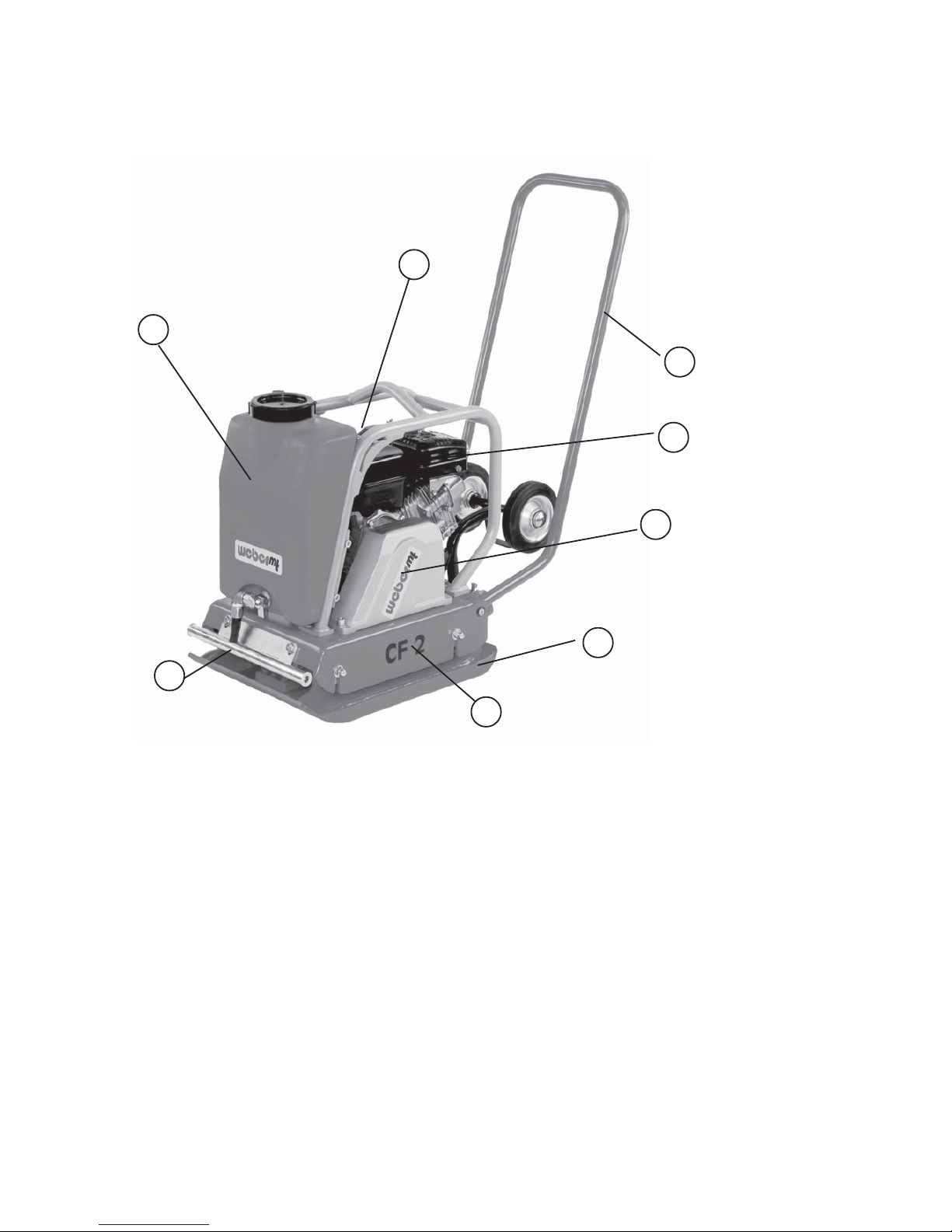
Figure 1 Overall View CF 2
1Water tank (option)
2Fuel tank
3Handle
4 Undercarriage (option)(not shown)
5 Engine bracket
2
3
5
6
8
6Base plate
7V-belt guard
8Water sprinkler system (option)
9Engine
Vukollan plate (option)
(not shown)
1
7
9
Page 7

CF-2 7
1.2 Machine Description
The CF 2 soil compactors are machines of the walk-behind type used for compaction in road and trench
construction.
Propulsion
The CF-2 is driven by a Robin gasoline engine (1/9) or a Honda gasoline engine.
Important!
Please refer to paragraph 1.3 (Specifications) for performance details of the engine and the whole
machine.
Function
The engine (1/9) drives the vibrator via a V-belt. The vibrator is screwed down to the base plate
(1/6) and sets it vibrating. The vibrating base plate performs the vibration work and travelling motion.
Accessories
A damper plate (2.4.3) and a water sprinkler system (1/1 and 1/8) are available as optional extras. An
undercarriage (1/4) can be fitted to the machine to facilitate transport work.
Operation
The compactor is started with a reversible starter (2.5).
The machine is steered by means of the handle (1/3). The engine speed is controlled directly at the engine
(2.5).
Page 8

8 CF-2
1.3 Specifications
CF 2 Robin CF 2 Honda
Weight
Operating weight CECE in kg 80 80
Dimensions
Overall length (in mm) 1030 1030
Overall width (in mm) 440 440
Height with handle folded down (in mm) 980 980
Base plate length, contact area (in mm) 345 345
Trans port dim ens ion s Lx W xH (in mm) 345x 440 345x 440
Propulsion
Engine Manufacturer Robin Honda
Type EX 17 D GX 160
Max. output acc. to DIN 70020(in kW (HP)) 4.2 (5,7) at 4000 rpm 4.0 (5.5) at 3600 rpm
Type of c ombus ti on 4-s t rok e, gas oli ne 4-s t rok e, gas oline
Max. operating speed 3600 3600
Travelling s peed forward (ac c . to s oil , i n m / min) 25 25
Gradeability (acc . to s oil, in % ) 30 30
Depth compaction (in cm) 20 - 25 20-25
Performance (in m²/h) 528 528
Vibration
System one-shaft vibrator one-shaft vibrator
Mode of driving mechanical mechanical
Frequency (in Hz) 98 98
Centrifugal force (in kN) 12 12
Page 9
CF-2 9
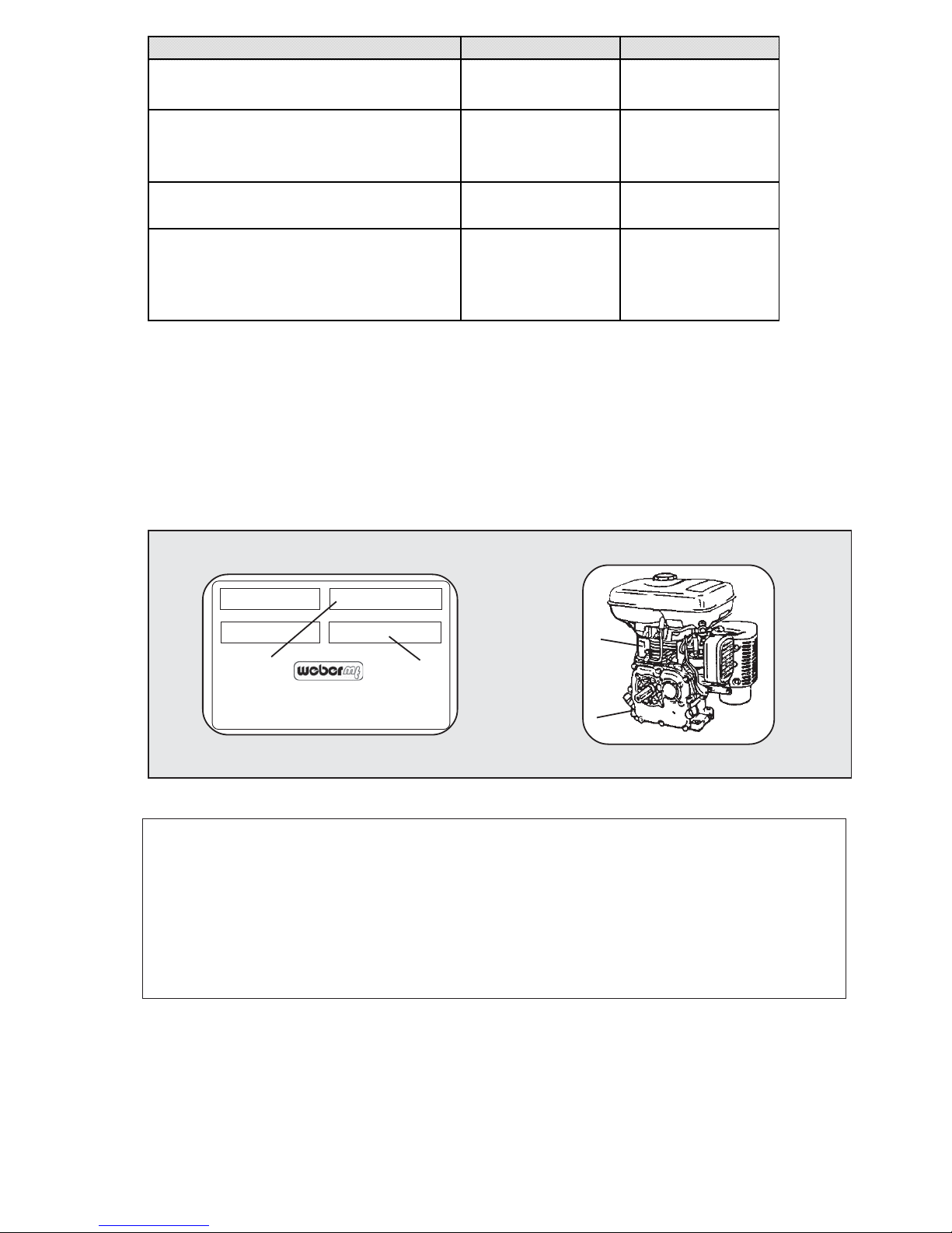
3 TYPE
.........................................
4 ENGINE/SERIAL NO.
.........................................
1MACHINE NO.
.........................................
2 YEAR OF CONSTRUCTION
.........................................
3
4
1
2
Weber Maschinentechnik GmbH
Typ
Masch.-Nr.
Betriebsgewicht
Baujahr
Postfach 2153
57329 Bad Laasphe-Rückershausen
CF 2 Robin CF 2 Honda
Noise a nd Vibra ti on Da ta
Sound pressure level LPA
(at the operator's place, acc. to 2000/14/E G, in
dB(A))
91 92
Sound power level LWA
(acc . to 2000/14/EG, in dB(A))
108 108
Hand/arm vibration
(Weighted root mean square acceleration at the
handle, determined acc. to 2002/44/EG, Part 1,
in m/s² )
79
* The indicated noise and vibration data were determined with the engine at nominal speed and the vibration
system turned on, 2000/14/EG. During operation, these data may vary according to the specific conditions
prevailing on the job site.
Page 10

10 CF-2
2Operation
2.1 Safety Precautions for the Operation
Before every shift, the operator must check the operativeness of all controls and safety elements as well as the
proper installation of all protective devices. The compactor is only allowed to be operated with all protective devices
in place. The control's functionality is not allowed to be impaired or annulled.
Before starting the compactor, the operator must take his personal noise protection measures. The engine is only
allowed to be started after is has been assured that the compactor cannot automatically start moving.
If defective safety devices or other failures which might affect the safe operation of the compactor are ascertained,
the supervisor must be informed without delay. In case of malfunctions endangering the unit's operational safety,
the machine must be turned off immediately.
During the machine's operation, the operator has to constantly supervise the operational safety of the compactor.
When running the machine , the operator is not allowed to leave the operating controls of the compactor. In
addition, he must always have a sufficient visibility on the compactor's zone of operation. The operator must be
assisted by a marshaller if the visibility on the zone of operation is restricted because of the operating conditions.
Soil compactors must be used and operated in a way ensuring their stability. The machine's stability is especially
endangered on slopes and brinks. Thus, keep clear of slopes and brinks.
When working on slopes, the operator must alway walk on the uphill side. Compaction work on slopes exceeding
the maximum gradeability of the compactor is prohibited. When working/travelling on slopes, always use extreme
precaution and drive/work directly in uphill or downhill direction.
Moist and loose bases considerably reduce the grip of the compactor on slopes. Increased danger of
accident!
Passing unevennesses or kerbs is only allowed at reduced speed. In addition, the soil compactor must be operated
in a way excluding any risk of injury caused by the handle swinging towards the operator.
Safety and Protective Devices
Conduct in Case of Failures
Conduct of the Machine Operator
Stability
Driving and Compacting
Pay attention to the slippage of the clutch!
Exhaust Precautions
Never inhale exhaust gasses. They contain carbon monoxide, a colorless, oderless and extremely
dangerous gas which can cause unconsciousness or death. Never operate the engine inddors or in a poorly
ventilated area, such as tunnerl, cave, etc. Exercise extreme care when operating the engine near people
or animals. Keep the exhaust pipe free of foreign objects.
Page 11
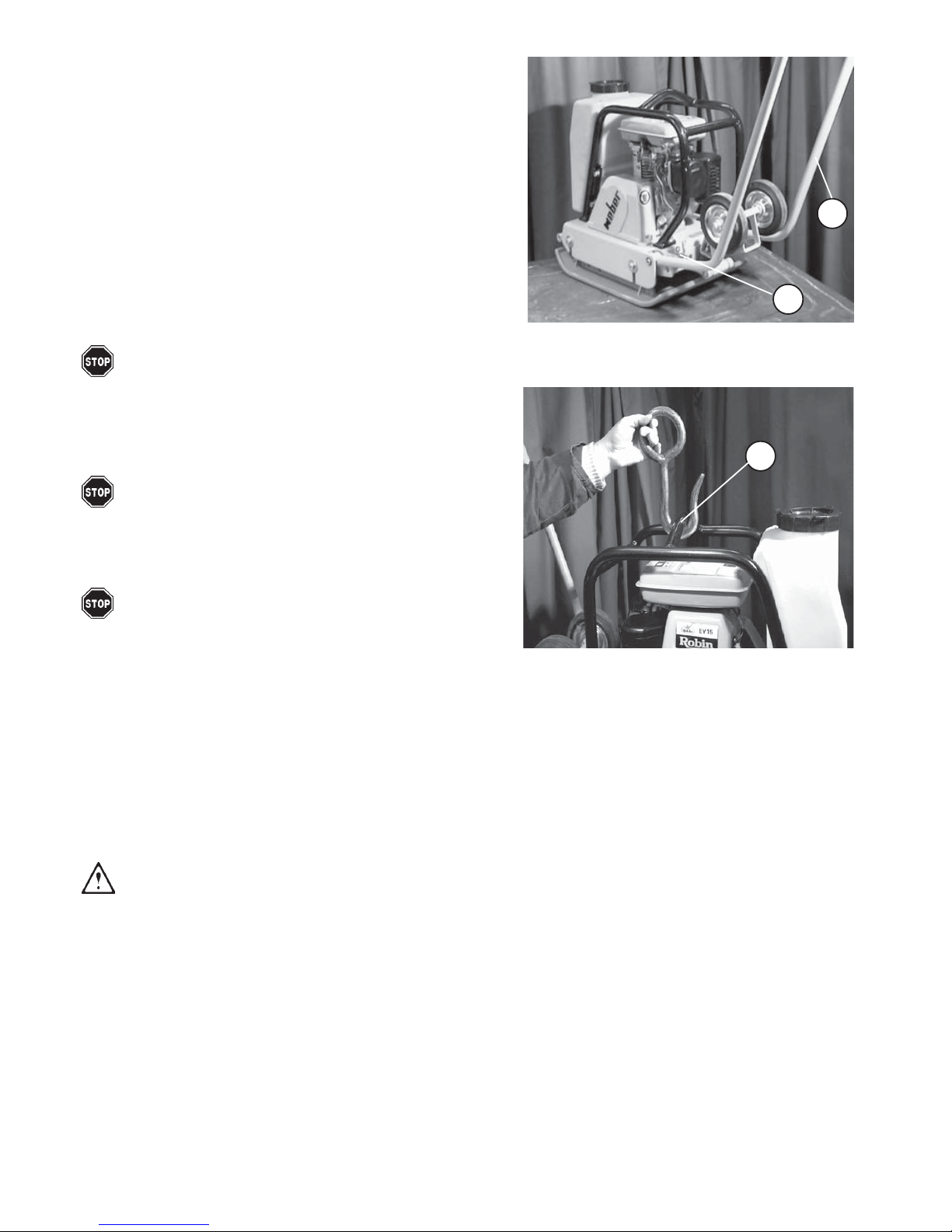
- Put the soil compactor out of operation as described in paragraph
2.7.
- Lock the handle (2/1) with the locking lever (2/2).
- Lift up the soil compactor at the protection frame with the help of
a second person.
Figure 2
Figure 3
1
2
1
2.2 Transport
Short distances on the job site can be covered by the compactor
under its own power in accordance with paragraph 2.6.
For transporting the compactor over long distances, however, the
machine can be transported by means of a special undercarriage
(refer to paragraph 2.4.4). In addition, the machine can be lifted on an
appropriate transport vehicle (truck, trailer) with a crane.
2.2.2 Manual Loading
2.3 Commissioning
Caution!
For commissioning, only carry out the pre-start work described in paragraph 2.4. Keep to the initial maintenance
intervals (refer to paragraph 3.2.1).
2.2.1 Loading by Crane
- Put the soil compactor out of operation as described in paragraph
2.7.
- Lock the handle (2/1) by means of the locking lever (2/2).
Danger!
Never use the handle (2/1) for lifting the machine by crane.
The machine may overturn!!
- Put the crane hook into the protection frame (3/1).
Danger!
Only use a lifting tackle and a crane of a sufficient bearing
capacity.
- Lift the soil compactor on the transport vehicle.
Danger!
Do not enter the zone under the suspended load!
2.4 Pre-Start Work
- Check to ensure that all safety devices are in place. Check the whole soil
compactor for evident damage (visual check).
-Check all screwed connections for tight seat, retighten them if necessary.
- Check the fuel level, if necessary, top up fuel (refer to paragraph 2.4.1).
- Check the engine oil level, if required top up engine oil (refer to
paragraph 2.4.2).
- If desired, fit the damper plate (refer to paragraph 2.4.3).
CF-2 11
- If the water sprinkler system is installed, check
the water level and top up the tank with clean
water if required (refer to paragraph 2.4.5).
-If desired, fit the undercarriage (refer to paragraph
2.4.4).
Page 12
12 CF-2
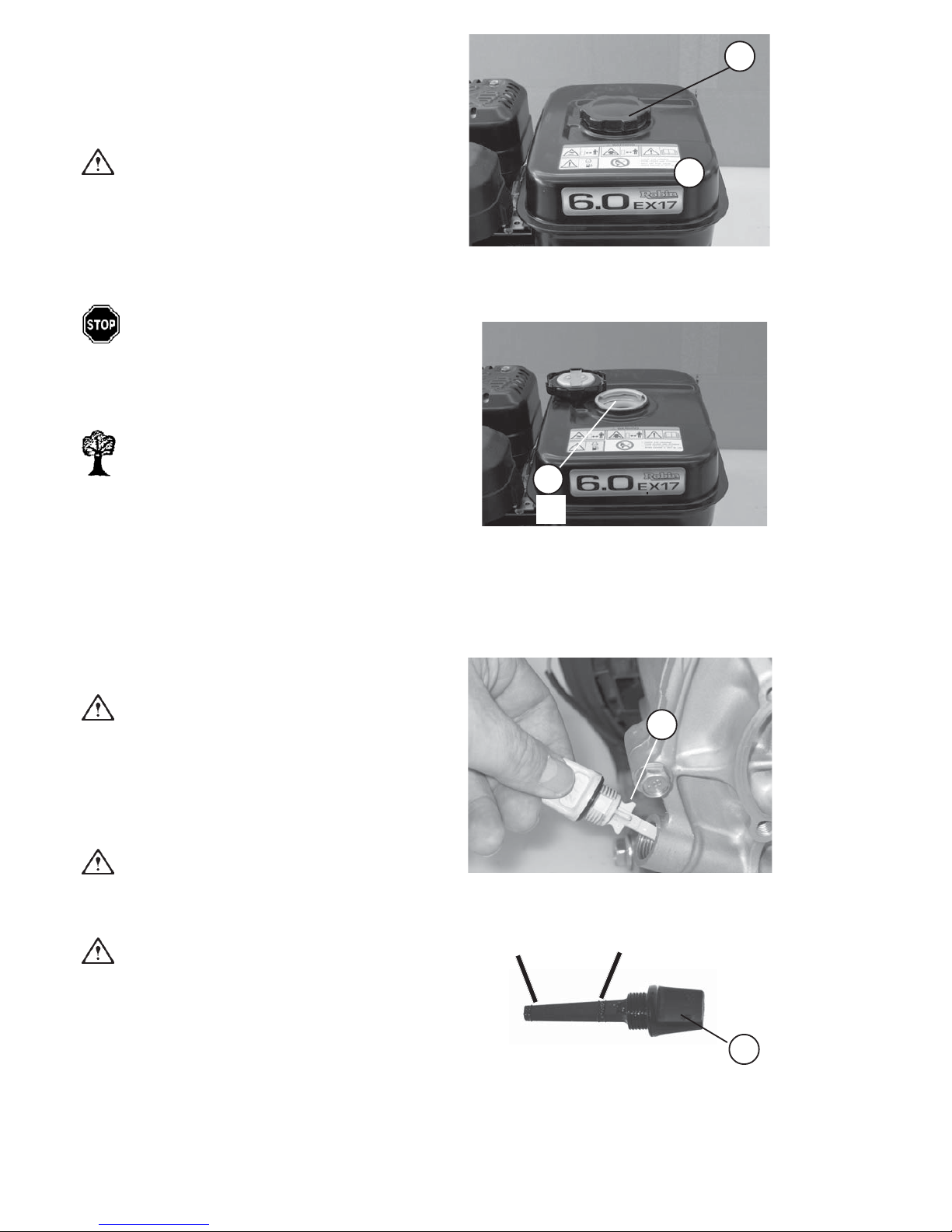
2.4.2 Checking the Engine Oil Level
Caution!
The engine oil level must be checked with the
compactor standing horizontally on the ground.
- Pull the oil filler screw with the oil dipstick (6/1) out,
wipe it with a clean, non-fluffing cloth and insert it
again.
Caution!
Do not screw down!!
- Pull out the oil dipstick once again.
Caution!
The oil level must reach up to the top mark (7/
max).
- If required, top up engine oil according to paragraph
3.3.1 (refer to paragaph 3.4 for quantities and
specifications).
- Firmly screw the oil dipstick down.
2.4.1 Checking the Fuel Level
-Put the soil compactor out of operation as described
in paragraph 2.7.
- Clean the area around the filler neck.
- Undo the tank cap (4/1) to open the fuel tank (4/2).
Caution!
Only fill the tank up with clean regular gasoline.
Refer to paragraph 3.4 for quantities and
specifications.
- Fill the tank up to the bottom edge of the filler neck
(5/1).
Danger !
Take care that fuel does not come in contact
with hot engine parts. Extinguish all open
flames and do not smoke while filling the
tank.
Environment Hazard!
Always wipe up any spilled fuel. Dispose of
fuel-soaked cloth in an environmentally-
friendly manner.
- Firmly close the fuel tank with the filler cap
(4/1).
Figure 4
1
max.
min.
1
Figure 6
Figure 7
Figure 5
2
1
1
Page 13
CF-2 13
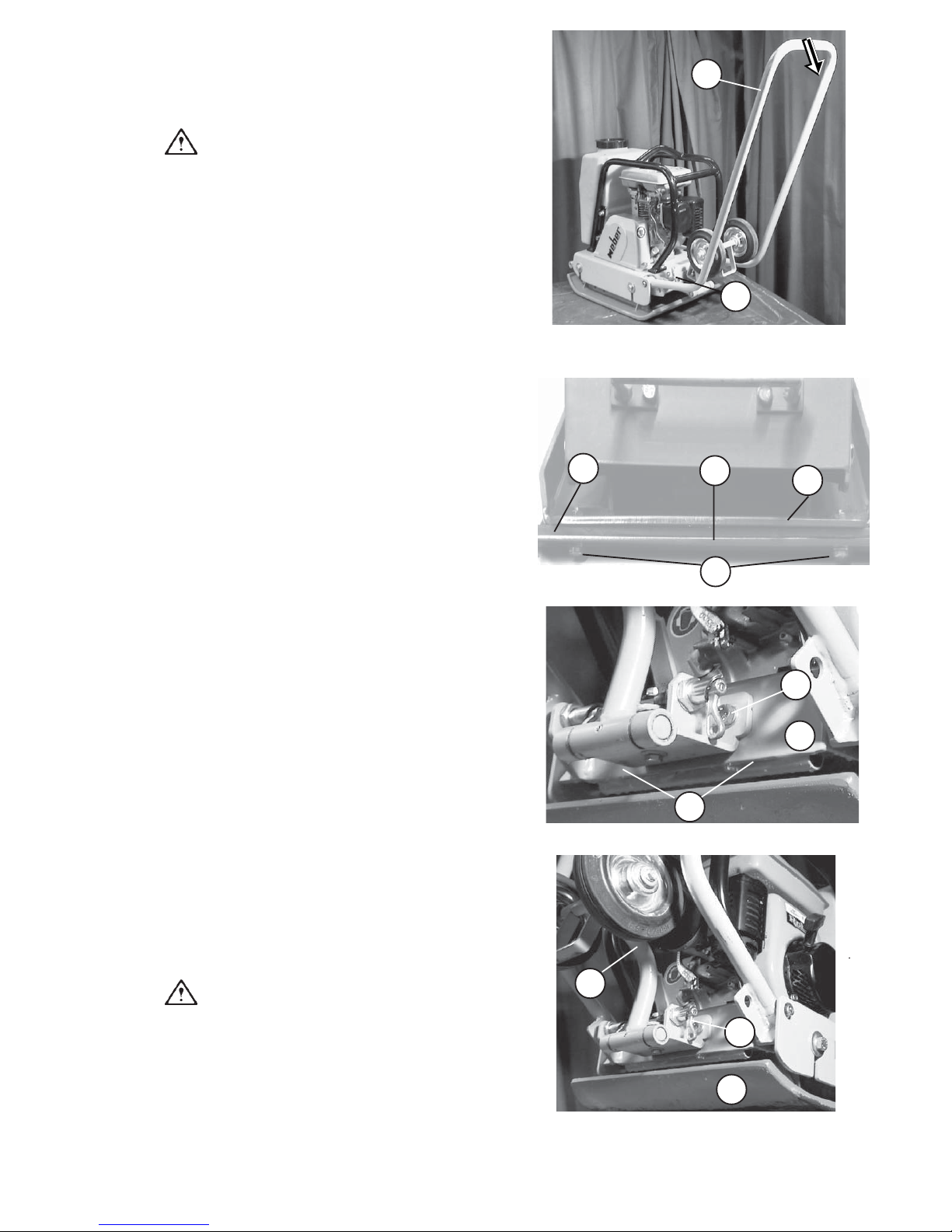
2.4.3 Fitting the Damper Plate
-Put the soil compactor out of operation as described
in paragraph 2.7.
- The spring bar (8/2) must be engaged.
Warning!
If the spring bar is not engaged, the soil
compactor cannot be held in tilted position.
- Push the handle (8/1) down to lift the front part of
the soil compactor.
- Put the damper plate (9/1) under the base plate (9/
4).
-Fix the damper plate (9/1) with the iron bar
(9/2) and the screws (9/3) at the front of the base
plate (9/4).
Figure 9
Figure 8
Figure 10
Figure 11
1
2.4.4 Fitting the Undercarriage
-Tighten the two screws (10/2) to fit the undercarriage
(11/1) to the engine bracket
(10/3).
- Push the handle (8/1) down and lock it by means of
the locking lever (8/2).
- Loosen the locking lever (11/2) and fold down the
undercarriage (11/1).
- Use the handle (8/1) to tilt the machine to the front
and swing the undercarriage (11/1) beneath the
base plate (11/3).
-In the working position, the undercarriage
(11/1) is folded up and locked in this position by
means of the locking lever (11/2).
Caution!
During compaction, the locking lever (11/2)
must be locked!!
2
1
1
3
2
2
3
1
4
3
2
Page 14
14 CF-2
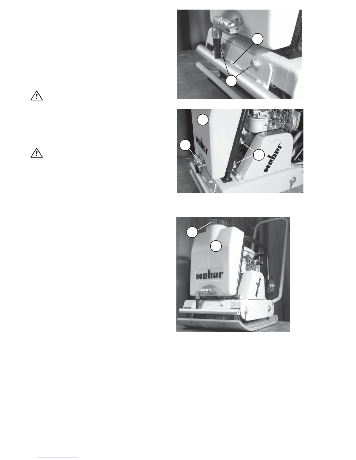
-Fasten the sprinkler tube (12/1) with the two screws
(12/2) at the front.
- Tighten the two screws (13/2) to fit the water tank
(13/1) to the protection frame.
- When the stop valve (13/3) is opened, water is
sprayed in front of the machine's base plate (12/1).
Caution!
Fill the water tank (14/1) up with clean water
only, because otherwise the water sprinkler
system (12/1) will get choked.
- Open the cap (14/2) to fill up the water tank.
Caution!
In case of danger of frost, completely drain
the water tank (14/1).
2.4.5 Fitting the Water Sprinkler System
Figure 12
Figure 13
Figure 14
2
1
1
2
1
2
3
Page 15
CF-2 15
2.5 Starting the Engine
Danger!
Before starting the machine, always ensure
that nobody is in the danger area of the
compactor and that all protective devices are
properly in place.
When starting the compactor in closed
premises, always ensure a proper ventilation
- Danger of poisoning!
Caution!
Never use starting aid sprays.
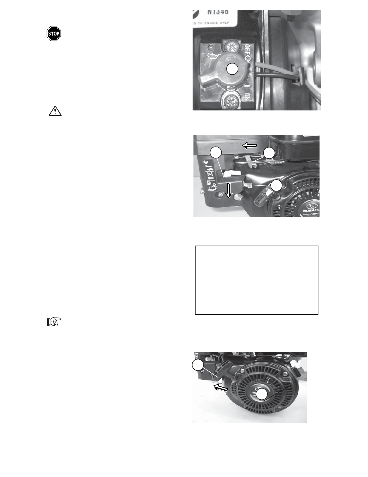
- Set the stop button (15/1) to START.
- Push the gas lever (16/1) approx. 1/3 to the left
side.
- Put the fuel stop cock (16/3) to vertical position to
open it.
- Open or close the choke (16/2) according to the
engine and/or ambient temperature.
a) In case of a cold engine and/or low ambient
temperatures, totally close the choke (16/2) (choke
to the left side).
b) In case of a warm engine and/or high ambient
temperatures, open the choke (16/2) half to all the
way (choke to the right side).
- Slowly pull the handle (18/1) of the reversible
starter (18/2) until a resistance is felt.
- Let the handle (18/1) recoil to its original position
and then firmly pull the cable with both hands to
start the engine.
Important!
If the engine fails to start, repeat the starting
procedure.
- As soon as the engine starts, let the starter cable
recoil into its housing (18/2).
- Slowly return the choke (16/2) in the fully open
position (choke to the right side) and let the engine
idle for warming up.
2.5.1 Starting the Robin Engine
Figure 15
1
open
Figure 16
Figure 17
2
Figure 18
Start
Stop
closed
1
3
1
2
1
Page 16
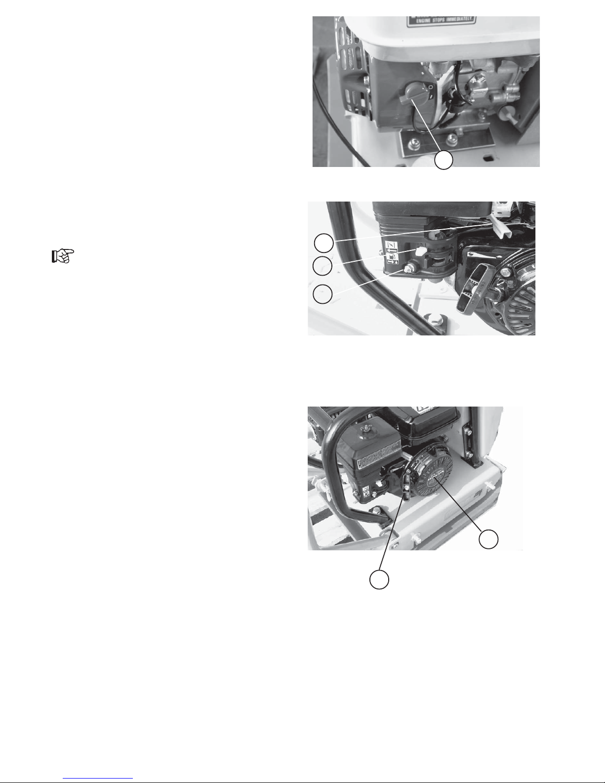
2.5.2 Starting the Honda Engine
- Put the stop switch (19/1) to START.
- Push the gasoline cock (20/1) to position "ON"
- Push the gas lever (20/2) approx. 1/3 to the left side.
- In case of a cold engine and/or low ambient temperatures,
fully close the choke (20/3) (choke to the left side).
-In case of a warm engine and/or high ambient temperatures,
open the choke (20/3) half to all the way (choke to the right
side).
- Slowly pull the handle (21/1) of the reversible starter (21/2)
until a resistance is felt.
- Let the handle (21/1) recoil to its original position and then
firmly pull the cable with both hands to start the engine.
Important!
If the engine fails to start, repeat the starting procedure.
- As soon as the engine starts, let the starter cable return into
its housing (21/2).
- Slowly return the choke (20/3) in the fully open position
(choke to the right side) and let the engine idle for warming
up.
Stop
Start
3
1
1
2
1
2
Figure 19
Figure 20
Figure 21
16
CF-2
Page 17
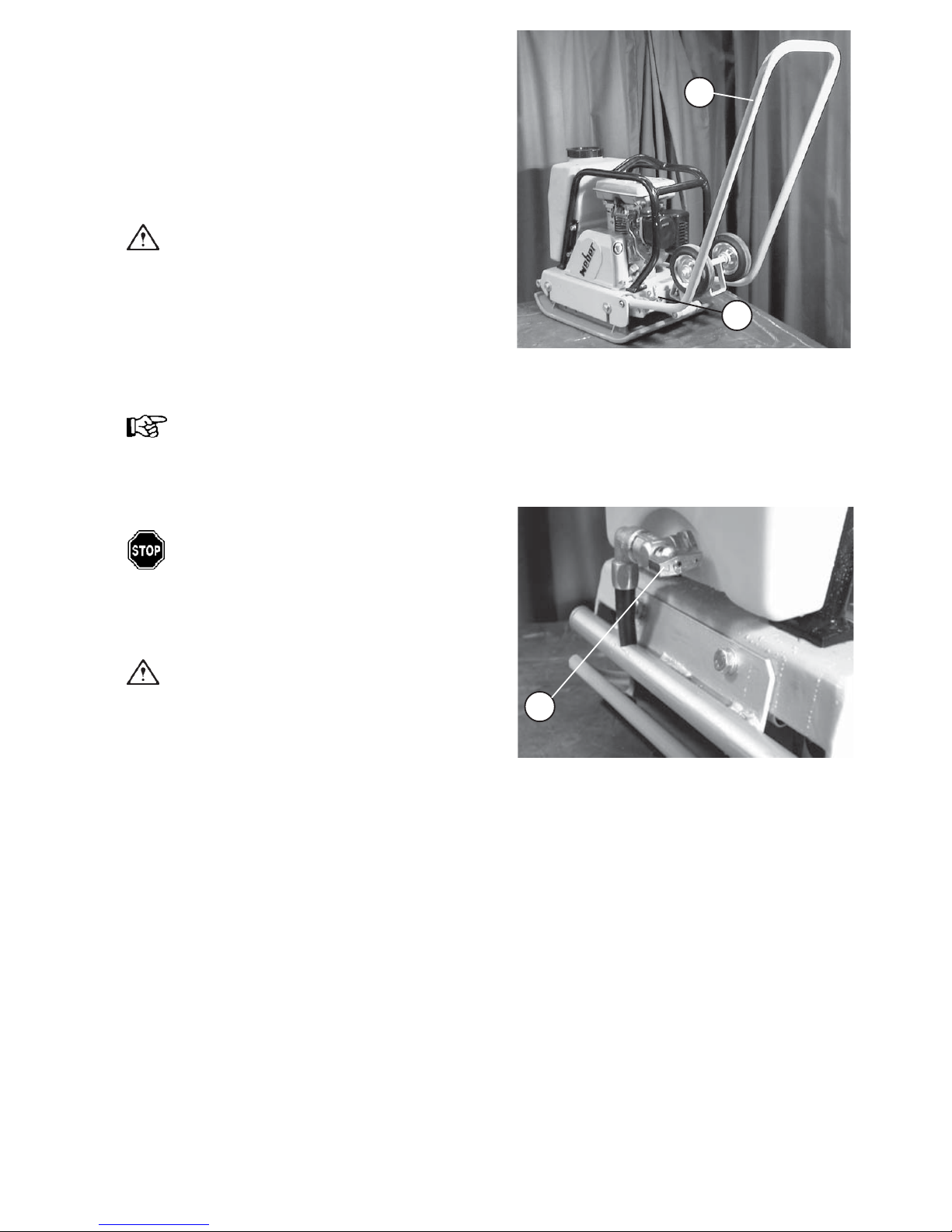
2.6 Compaction Work
-Start the soil compactor (refer to paragraph 2.5).
When the engine has warmed up:
- Push the engine speed adjusting lever (16/1) to
the right side on the Robin engine and fully to the
left side to full speed position (20/2) on the
Honda engine.
Caution!
Compaction work is only allowed to be
done at full engine speed, otherwise the
centrifugal clutch may slip and cause
increased wear.
During compaction work, the spring bar
(22/2) must be unlocked!!
Important!
As soon as the centrifugal clutch achieves
the cutting-in speed, the vibrator is
automatically turned on.
Danger!
If obstructions (such as walls or trenches)
are encountered, take care that persons
do not get crushed and that the machine
does not slip out of control.
Warning!
During work breaks, even if they are short,
the soil compactor must be put out of
operation (refer to 2.7).
-Use the handle (22/1) to steer the soil compactor
into the desired direction.
-If installed, open the water stop cock
(23/1).
Figure 22
Figure 23
CF-2 17
2
1
1
open
closed
Page 18
Before work breaks and at the end of every day's shift,
the compactor must be parked on a stable base which
should be as horizontal as possible.
Warning!
If the compactor causes an obstruction when
being parked, precautionary measures must
be taken in order to make the machine visible.
If the machine is parked on traffic roads, the
safety precautions required by the traffic
regulations must be additionally observed.
Caution!
Never stop the engine while it is running at full
speed, but let the engine idle for some minutes.
2.7 Putting the Compactor out of
Operation
Stop
1
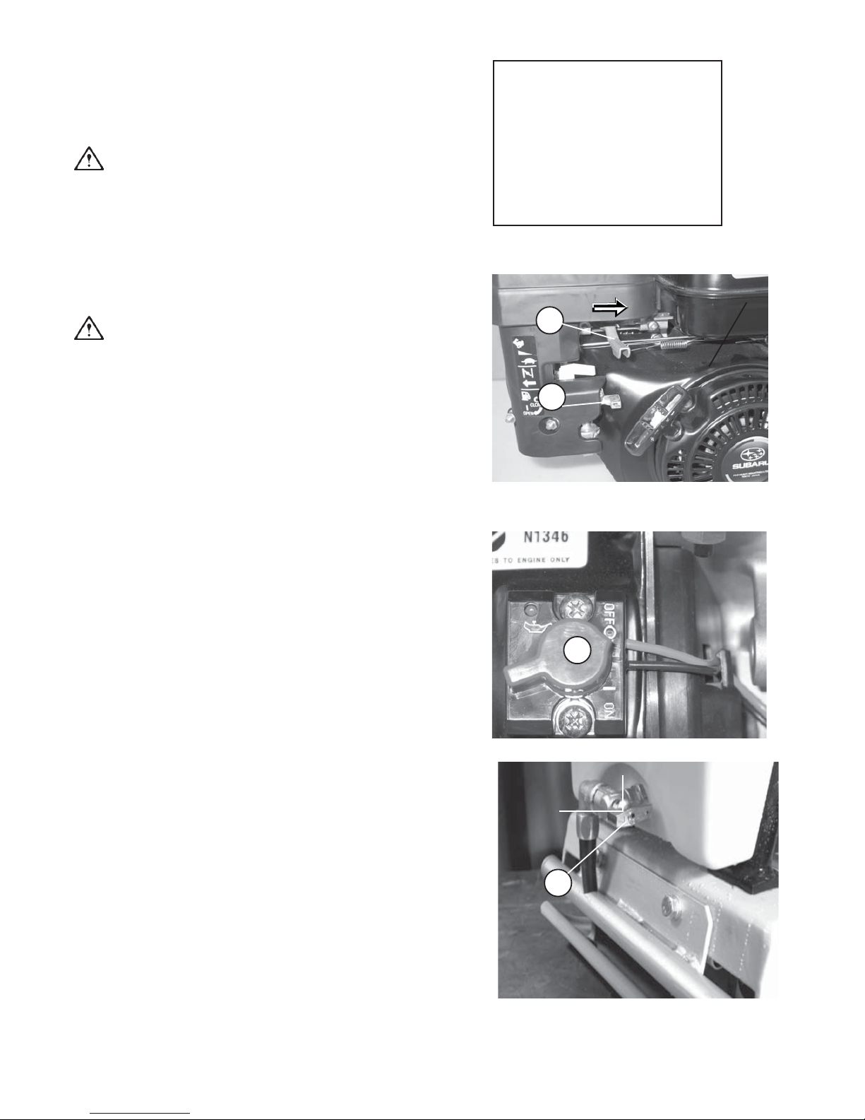
2.7.1 Stopping the Robin Engine
open
closed
closed
Open
-Push the engine speed adjusting lever (25/1) in the direction
of the arrow to the right side and let the engine idle for some
time.
- Close the fuel stop cock (25/2).
- Turn the stop button (26/1).
- If installed, close the water stop cock.
Figure 24
Figure 25
Figure 26
Figure 27
18 CF-2
1
2
1
Page 19
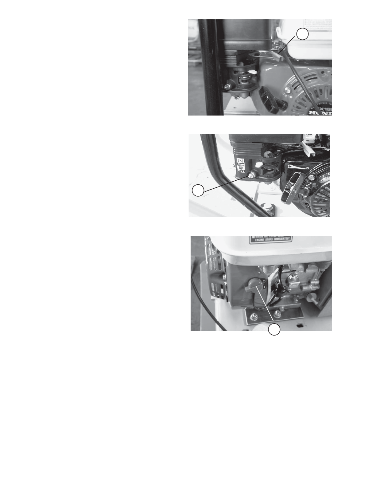
2.7.2 Stopping the Honda Engine
-Push the gas lever (28/1) to the right side and
let the engine idle for some minutes.
- Push the gasoline cock (29/1) to the left side
to the "OFF" position.
- Turn the stop cock (30/1) into the direction of
"STOP".
- If installed, close the water stop cock (27/1).
Figure 28
Figure 29
Figure 30
1
Stop
1
1
CF-2 19
Page 20

3Maintenance
3.1 Safety Precautions for Maintenance Work
Checks
Depending upon the operating conditions, soil compactors must be made subject to an expert's check for
operational safety when required, but at least once a year. The inspection results must be recorded in writing
and kept at least until the next inspection.
Service Work
Service work is only allowed to be done when the drives are stopped. Exceptions are only allowed if work can
be done with running drives only. In addition, the compactor must be secured against unintentional movements.
Drained off consumables must be collected and stored in an appropriate receptacle and disposed off
according to the relevant environmental protection regulations.
Prior to any work on parts which are not protected, the engine must be secured against unintentional starting.
After completion of service work, all protective devices must be properly installed again.
Modifications and Retrofittings
For safety reasons, any modifications and retrofittings made on the soil compactor without the manufacturer's
authorization, are prohibited. Damage resulting from modifications or retrofittings is excluded from the
manufacturer's liability. Only use genuine WEBER spare parts to ensure a safe and reliable operation.
Safety Precautions Required by the Engine Manufacturer
Please refer to the annexed operation manual of the engine manufacturer ROBIN/HONDA for a detailed
description of the maintenance work to be done on the engine.
20 CF-2
Page 21

3.2 Maintenance Survey
Any maintenance work which must be performed on the compactor is listed in two charts. The first chart (paragraph
3.2.1) indicates the initial maintenance work which has to be carried out once at a certain time after commissioning.
The routine maintenance work indicated in the second chart (paragraph 3.2.2) has to be repeated at regular
intervals.
Both charts have the same lay-out. The column "Maintenance Interval" indicates the time or the operating hours
at which (after which) the maintenance work must be done.
If two time data are given, maintenance work has to be carried out at the time which occurs at first.
The column "Maintenance Item" refers to the assembly group on which the work indicated in the column
"Maintenance Work" must be carried out.
The column "Remarks/Notes" contains cross-references on paragraphs of these operating and maintenance
instructions or other documentation in which the maintenance work is described in detail.
3.2.1 Initial Maintenance
CF-2 21
Maintenance Interval Maintenance
Item
Remarks/
Notes
After the first 10 ope rating
hours
Vibrator -
Check, and if nec es s ary,
increase the V-belt tension
# 3.3.4/5
After the first 20 ope rating
hours
Engine - Change the engine oil # 3.3.1
Vibrator - Change the oil # 3.3.6
Whole machine -
Check all screwed
connections for tight seat,
retighten them, if required
Maintenance Work
Page 22

3.2.2 Routine Maintenance
22 CF-2
Maintenance
Interval
Maintenance
Item
Remarks/
Notes
Eve ry 8 op e rating h ours
Whole machine -
Check for visible damage,
leaks etc.
Air filter -
Clean and chec k the air filter
element for damage, replace it
if required
# 3.3.2
Engine - Check the engine oil level # 2.4.2
Vibrator -
Check, and if required,
increase the V-belt tension
# 3.3.4
Engine - Change the engine oil # 3.3.1
- Clean the spark plug
-Clean the air filter # 3.3.2
Eve ry 100 op e ra ting
hours
Whole machine -
Check all sc rewed
connections for tight seat,
retighten them if neces s ary
Engine - Clean the fuel filter # 3.3.2
-
Clean t he s park plug and
adjust the air gap
Manual of the
engine
manufacturer
All bare parts - Apply a slight film of oil
Eve ry 500 op e ra ting
hours
Vibrator - Change the oil # 3.3.6
Engine -
Clean, and if required, adjust
the carburettor
Manual of the
engine
manufacturer
-Clean the cylinder head
-Adjust the valve cleance
Whole machine -
Check all groups for visible
damage and wear
-
Remove dirt, old grease and
rust
Eve ry 200 op e ra ting
hours
Eve ry 2000 ope ra ti n g
hours
Maintenance Work
Eve ry 50 operati ng
hours
Page 23
3.3 Description of the
Maintenance Work
3.3.1 Changing/Adding Engine Oil
- Put the soil compactor out of operation as
described in paragraph 2.7.
Caution!
Drain off the engine oil at operating
tempertature and with the soil compactor
standing horizontally on the ground only.
- Put a drain pan under the outlet.
Environment Hazard!
Choose a drain pan having a sufficient capacity
to catch all the used oil. Do not let used oil run
into the soil. Dispose of the collected used oil
in an environmentally-friendly manner (acc.
to statutory pollution control regulations).
Wipe up any oil residues and dispose of the
oil-soaked cloth in an environmentally-friendly
manner.
Danger!
Danger of scalding because of hot oil.
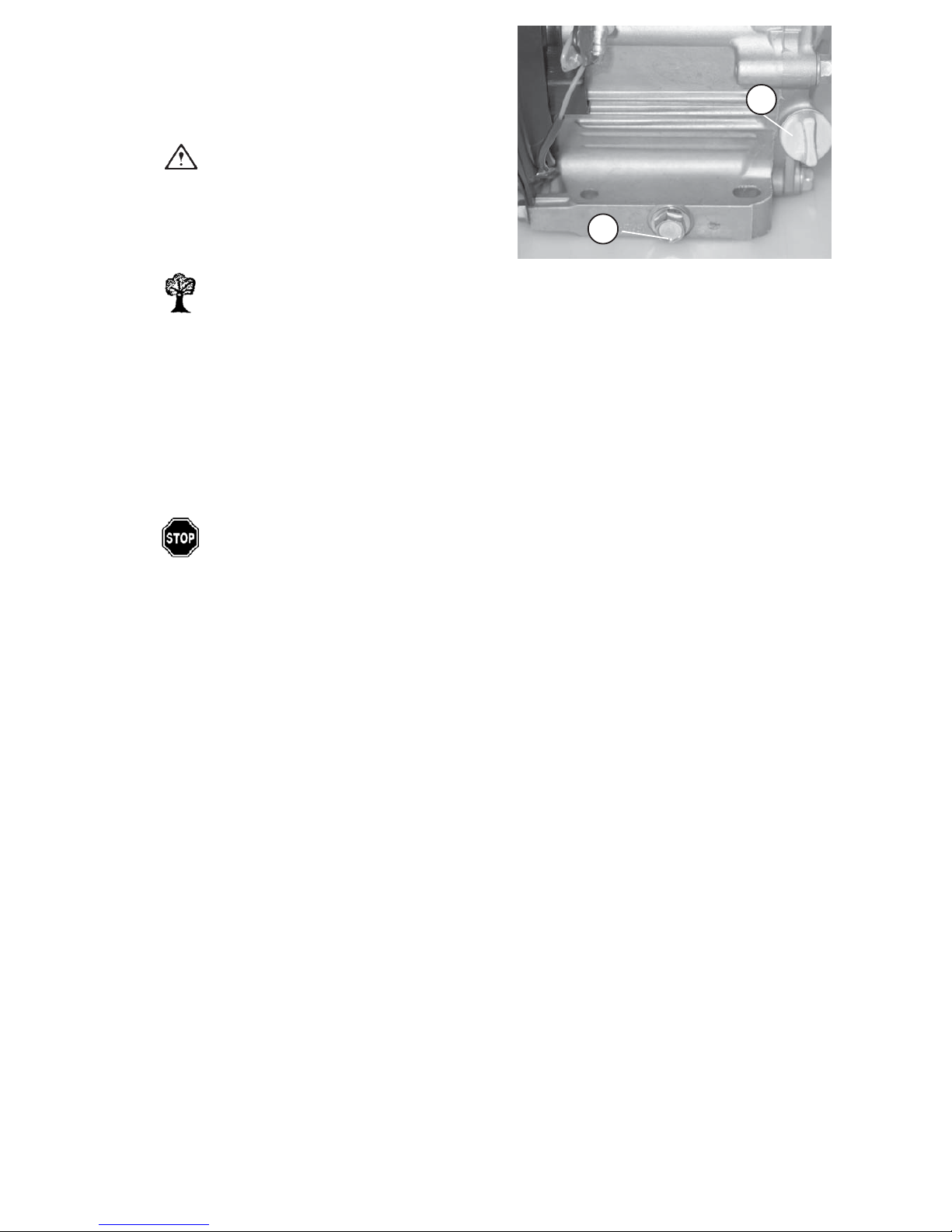
- Undo the oil filler screw/dipstick (31/1).
- Undo the oil drain screw (31/2) and completely
drain the engine oil.
- Screw the oil drain screw (31/2) down again (use a
new gasket).
- Add engine oil through the oil filler opening (31/1)
according to the quantity chart (3.4).
-Check the oil quantity by means of the plug/dipstick
(31/1) (refer to paragraph 2.4.1).
- Close the tank with the plug/disptick (31/1) and
check the system for tightness.
Figure 31
2
1
CF-2 23
Page 24
3.3.2 Cleaning/Replacing the Air Filter
Cartridge
Figure 33
Figure 32
1
2
2
1
24 CF-2
1
2
3.3.2.1 CF 2 Robin
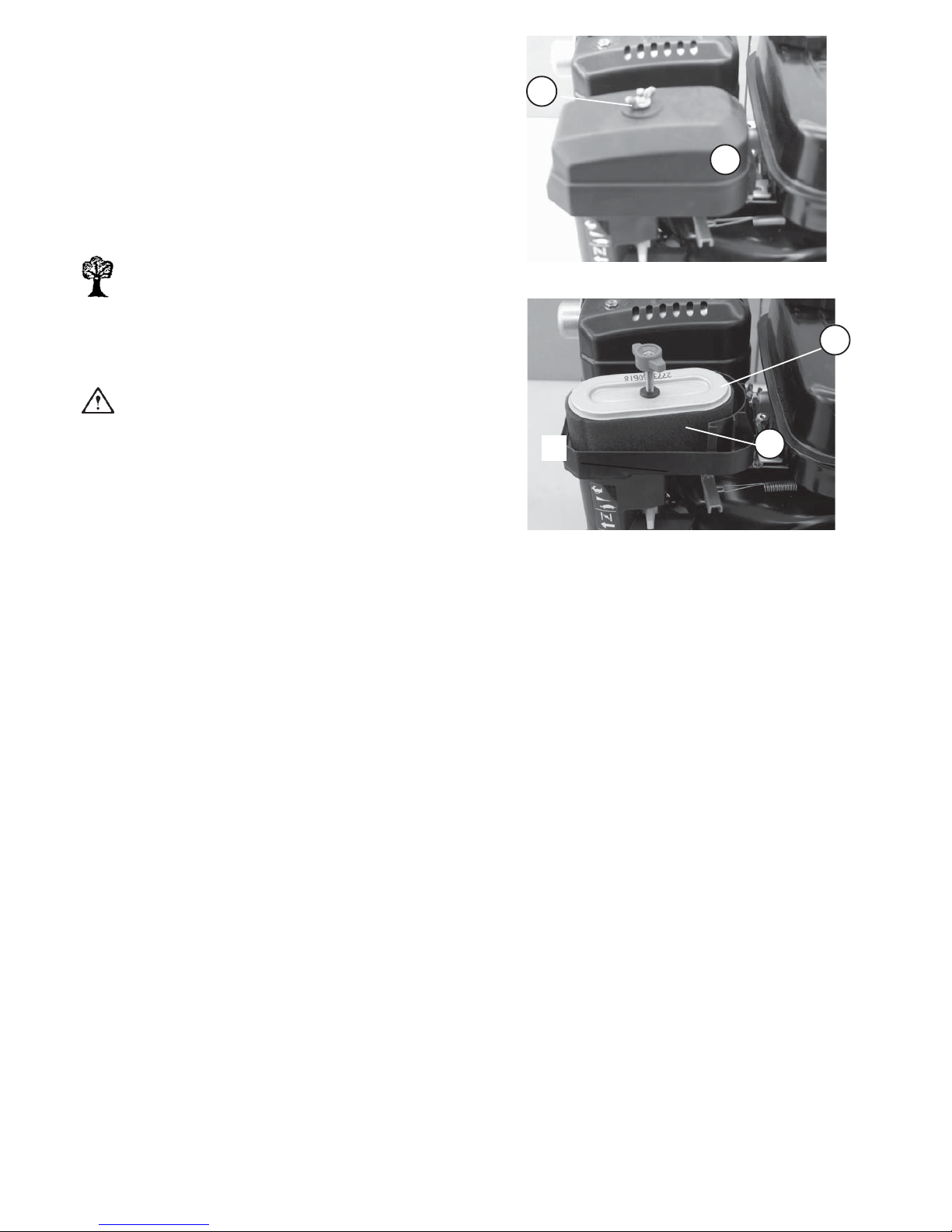
- Remove the wing nut (32/1) and the air filter cover (32/2).
- Pull out the air filter element (33/2) and the pre-cleaner
(33/3).
- Wash the pre-cleaner (33/3) in benzine and let it dry.
Environment Hazard!
Dispose of the washing solution in an environmentally-
friendly manner.
- Knock or blow the air filter element (33/1) clean.
Caution!
If this procedure does not provide a sufficient cleaning
(e. g. because of humid or oily dirt), a new filter
element must be used.
- Insert the filter again.
- Fit the air filter cover (33/2) with the wing nut (32/1).
Page 25
2
3.3.2.2 CF-2 Honda
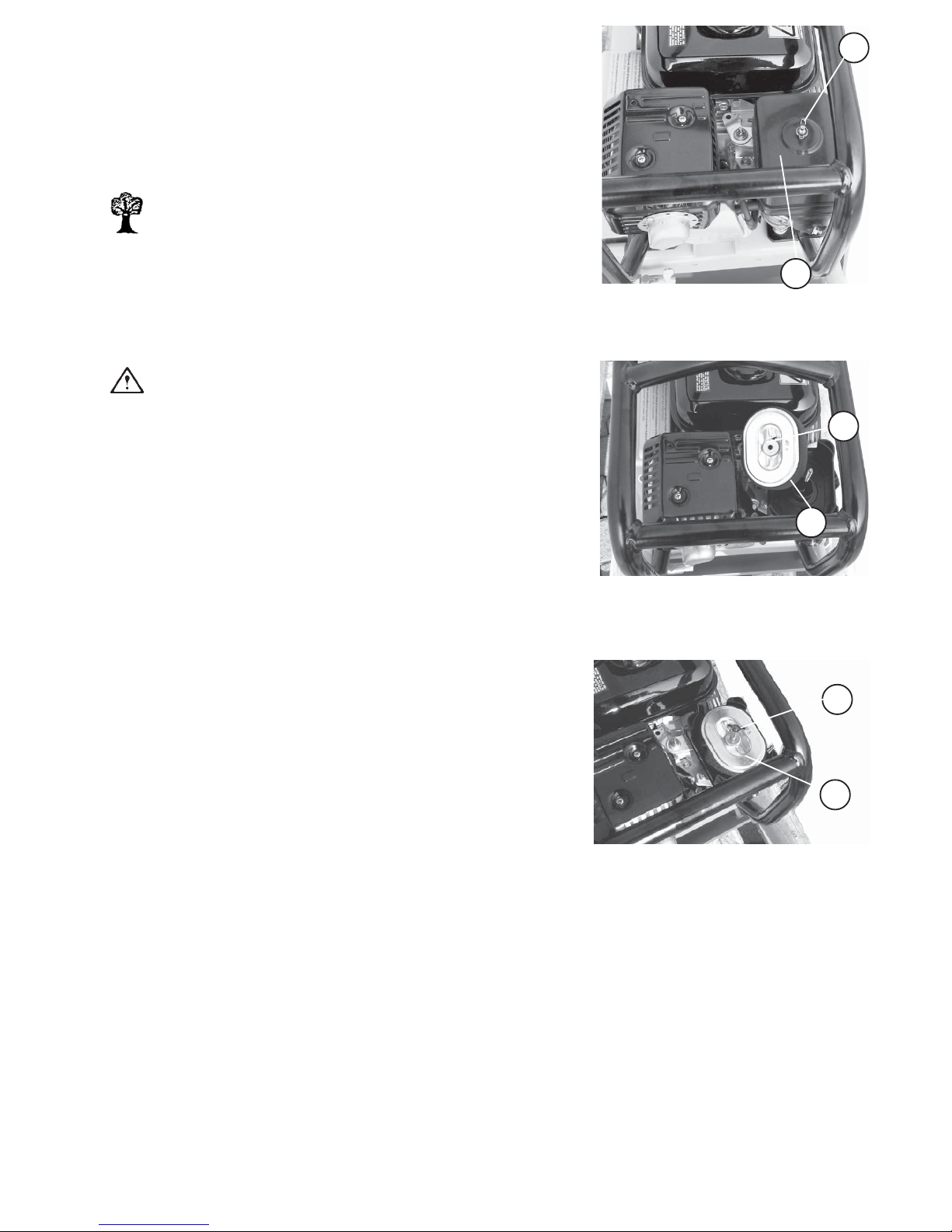
- Remove the wing nut (34/2) and the air filter cover (34/1).
- Pull out the air filter element (35/1) and remove the foam pre-cleaner (35/
2).
- Wash out the foam pre-cleaner (35/2) in benzine and let it dry.
Environment Hazard!
Dispose of the washing solution in an environmentally-friendly
manner.
- Knock or blow the air filter element (35/1) clean.
Caution!
If this procedure does not provide a sufficient cleaning (e.g. because
of humid or oily dirt), a new filter element must be used.
- Insert the filter (36/1) again and fasten it with the thumb nut (36/2).
-Put the cover (34/1) on the air filter and fasten it with the thumb nut (34/
2).
2
2
2
2
1
Figure 34
Figure 35
Figure 36
1
1
CF-2 25
Page 26
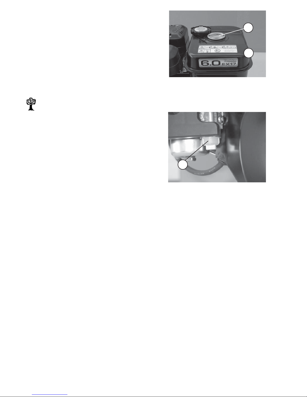
Figure 37
1
Figure 38
3.3.3 Cleaning/Replacing the Fuel Filter
-Put the soil compactor out of operation as described
in paragraph 2.7.
3.3.3.1 CF 2 Robin
-Take the cover off the tank (37/2).
- Take the strainer (37/1) out of the tank (37/2) and
clean it.
- Reinstall in inverse order.
Environment Hazard!
Immediately wipe up any escaping fuel,
dispose of the fuel-soaked cloth in an
environmentally-friendly manner.
- Undo the sight glass (38/1) beneath the fuel stop
cock (38/2).
- Take the strainer out of the sight glass (38/1) and
clean it.
- Reinstall in inverse order and check for tightness.
1
26 CF-2
2
Page 27
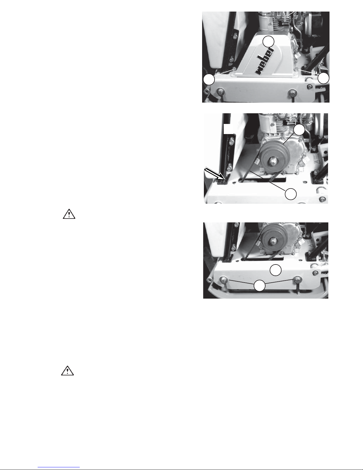
3.3.5 Replacing the V-Belt
- Remove the V-belt guard (39/1) by loosening the
screws (39/2).
- Loosen the V-belt as described in paragraph 3.3.4
and remove the V-belt.
- Put on the new V-belt (pay attention to its length !!).
Caution!
Take care to properly align the belt, especially
after repair work.
-Tension the V-belt as described in paragraph 3.3.4.
-Put the soil compactor out of operation as described
in paragraph 2.7.
- Remove the V-belt guard (39/1) by undoing the
screws (39/2).
- Check the condition of the V-belt (40/1) (cracks,
broken out flanks, wear).
- In case of excessive wear, replace the V-belt as
described in paragaph 3.3.5.
- Apply a force of approx. 100 N and press the V-belt
down as shown in figure 40. The V-belt's deflection
should be approx. 10 mm.
If the V-belt's tension is too low, proceed as follows:
- Tension the V-belt by means of the 4 fastening
screws (41/1) of the engine bracket (41/2).
- Loosen the fastening screws and lift the engine
bracket with a fitting lever.
- When the V-belt (40/1) has achieved the correct
tension, retighten the fastening screws (41/1).
Caution!
Take care to properly fit the V-belt on the
pulleys (40/2) (belt alignment).
- Fasten the V-belt guard (39/1) by means of the
screws (39/2).
3.3.4Checking the Condition and
Tension of t h e Vibrator V- B e lt
1
2
2
Figure 39
Figure 40
1
2
Figure 41
2
1
CF-2 27
Page 28
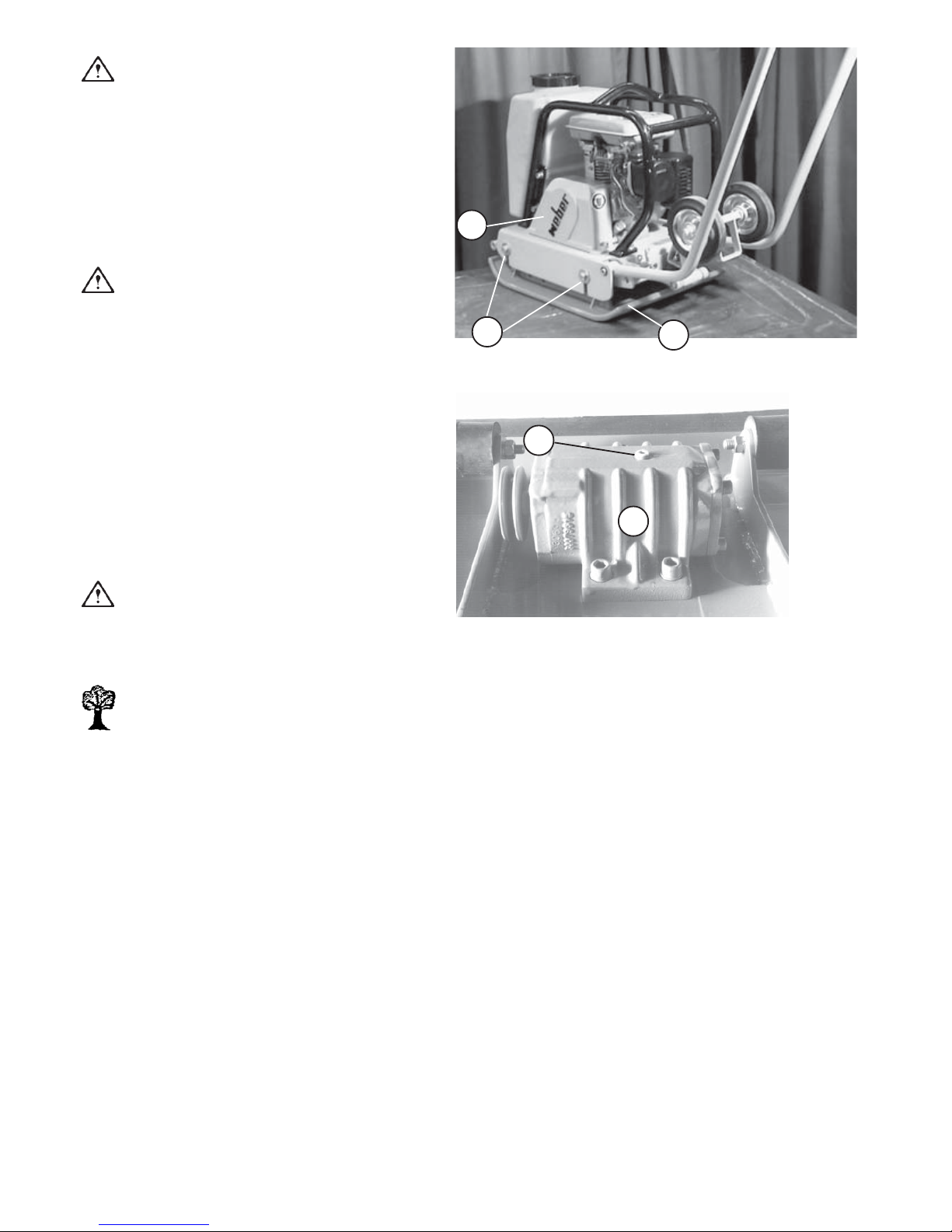
3.3.6 Changing the Vibrator Oil
Caution!
Change the oil at operating temperature only.
- Remove the V-belt guard (42/1).
- Loosen the V-belt (refer to paragraph 3.3.5).
- Undo the four screws (42/3) on both sides of the
engine bracket (42/2).
- Take the engine bracket off the base plate.
Caution!
Thouroughly clean the oil drain/oil filler screw
and the area around the drain filler opening.
- Put an appropriate drain pan under the outlet.
- Undo the oil filler and drain screw (43/1).
-Turn the base plate (42/2) with the vibrator
(43/2) and let the oil escape into the drain pan.
- After the used oil has completely flown off, turn the
base plate round.
- Pour engine oil in (refer to paragraph 3.4 for
quantities and specifications).
- Screw the oil filler/drain screw (43/1) down.
Caution!
Take care that the contact surfaces of the oil
filler and drain screw and of the vibrator housing
are clean.
Environment Hazard!
Dispose of the collected used oil in an
environmentally-friendly manner. Take care
that the environment is not polluted by oil.
- Put the engine bracket with the engine on the base
plate.
- Put on and tension the V-belt as described in
paragraph 3.3.4.
- Tighten the screws (42/3).
-Fit the V-belt guard (42/1) as described in paragraph
3.3.4.
Figure 43
Figure 42
1
1
3
2
2
28 CF-2
Page 29

3.4 Consumables and Quantities
CF-2 29
Assembly
Group
Consumable Quantity Quantity
Summer Winter CF-2R CF-2 HD
Quality
Engine
Engine oil SAE 10 W 40 0.6 l 0. 6 l
(-10 ~ + 50 °C)
API - CD CE
or SHPD
or CCMC - D2 - D3 - PD1
Fuel tank
Regular gasoline, unleaded 3.6 l 2.5 l
Gasoline
Vibrator
Engine oil 10 W 40 / 15 W 40 0.05 l 0.05 l
as required as required
acc. to DIN 51825 - KPF2
High-pressure grease (lithium saponified)
Greasing points
Page 30

4Malfunctions During Operation
4.1 General
If a malfunction occurs on the soil compactor, proceed as follows:
- Put the soil compactor out of operation as described in paragraph 2.7.
- Determine the source of the malfunction (refer to paragraph 4.2 - Trouble Shooting).
- Eliminate the malfunction (refer to paragraph 3 (maintenance work) and paragraph 2 (Description of the
various controls).
Please refer to the manual of the engine manufacturer with regard to the repair of the engine
malfunctions.
The detailed description of the various controls and the references given in the column "Remarks/Notes"
of the maintenance survey chart (paragraph 3) and trouble shooting chart (paragraph 4.2) allow a quick
failure elimination on condition that the given order is precisely kept towhen service work is carried out.
Any service work has to be made with appropriate tools and in accordance with the safety
regulations set out in this operating and maintenance manual.
If a problem persists although a component or assembly group has been replaced, repair work has to be
continued with the work described next. If a failure cannot be rectified although the described service work
has been carried out or if a defect is not described in the operating and maintenance instructions, the failure
must be repaired by authorized service personnel.
30 CF-2
Page 31

4.2 Trouble Shooting
CF-2 31
Failure Possible Cause Remedy Remarks
Mistake in operating the unit
Perform the start procedure
as desc ribed
# 2.5
Lack of fuel Check the fuel level # 2.4.1
Dirty fuel filter Replace the fuel filter # 3.3.3
Dirty air filter
Clean/replace t he air filter
cartridge
# 3.3.2
No vibration, no or
unsufficient forwa rd
or reverse travel
Defective vibrator V-belt Replace the vibrator V-belt # 3.3.5
Soil compactor does
not start
Page 32

5Preserving the Machine
If the soil compactor is planned to be put out of operation for an extended period of time (approx. 1 ... 6 months),
e. g. during the winter season, it must be stored in a frost-proof and dry room. Before storing the machine, however,
the preservation measures described in paragraph 5.1 must be taken. After the storage, the soil compactor must
be put in operation according to paragraph 5.2.
If the soil compactor is to be stored for more than 6 months, additional measures must be taken in
accordance with your WEBER service.
5.1 Preservation Measures
5.2 Removing Machine Preservatives
32 CF-2
Assembly Group Remarks
Whole soil compactor
-Thoroughly clean
-Perform pre-start work # 2.4.
Measures
Assembly Group Remarks
Whole soil compactor
-Thoroughly clean
-Check condition, fastenings and tightness
-If required, have the failures ascertained repaired
Engine
-Check the oil level, add oil if required # 2.4.2
All ba re pa rts
-Apply a slight film of oil
Fuel tank
-
Top t he t ank up t o t he lower edge of t he filler nec k
with regular gasoline, unleaded
# 2.4.1
Measures
Page 33

Page 34

Page 35

66
66
6
Weber Maschinentechnik GmbH
CF-2 33
For problems, questions and further information refer to one of the following addresses:
in Germany WEBER Maschinentechnik GmbH
Postfach 2153
57329 Bad Laasphe - Rückershausen
Telefon
Telefax
E-Mail
+ 49 (0) 2754 - 398-0
+ 49 (0) 2754 - 398101-switchboard
+ 49 (0) 2754 - 398102- spare parts-
directlinie
in Netherlands WEBER Machinetechniek B.V.
Graafschap Hornelaan 159
6001 AC Weert
Telefon
Telefax
E-Mail
+ 31 (0) 495 - 530215
+ 31 (0) 495 – 541839
in France
WEBER Technologie SARL
26’ rue d’ Arsonval
69680 Chassieu
Telefon
Telefax
E-Mail
+ 33 (0) 472 -791020
+ 33 (0) 472 – 791021
in Poland
WEBER Maschinentechnik
Sp. zo.o.
Ul. Grodziska 7
05-830 Stara Wies
Telefon
Telefax
E-Mail
+ 48 (0) 22 - 739 70 - 80
+ 48 (0) 22 - 739 70 - 81
+ 48 (0) 22 - 739 70 – 82
in
USA and
Canada
WEBER Machine (USA), Inc.
40 Johnson Ave 112
Bangor, ME 04401
Telefon
Telefax
E-Mail
+ 1(207) - 947 - 4990
+ 1(207) - 947 - 5452
in South -
America
WEBER Maschinentechnik do Brasil
Ltda.
Rua Sete de Setembro, 275
93332 – 470 Novo Hamburgo, RS
Brasil
Telefon
Telefax
E-Mail
+ 55 (0) 51- 587 3044
+ 55 (0) 51- 587 2271
Page 36

> Vibratory Plate Compactors
> Vibratory Tampers
> Vibratory Rollers
> Joint Cutters
> Poker Vibrators and Converters
> Vibrating Motors
> Stone Saws
> Rotary Trowels
> and many others
Weber MASCHINENTECHNIK GmbH
Im Boden
D- 57334 Bad Laasphe - Rückershausen
P. O. Box 2153
D - 57329 Bad Laasphe
Phone ++27 54 / 398 0 - Telefax ++27 54 / 398 101
 Loading...