

Page 1
GAS GRILL
Built-In LP Gas Grill Installation Guide
Tank Enclosure Installation - Pg 25
S-460
S-660
™
™
#43267
YOU MUST READ THIS OWNER’S GUIDE
BEFORE OPERATING YOUR GAS GRILL
DANGER
If you smell gas:
1. Shut off gas to the appliance.
2. Extinguish any open flames.
3. Open lid.
4. If odor continues, keep away from the
appliance and immediately call your gas
supplier or your fire department.
Leaking gas may cause a fire or explosion
which can cause serious bodily injury or death,
or damage to property.
WARNING: Follow all leak-check procedures
carefully in this manual prior to barbecue
operation. Do this even if the barbecue was
dealer-assembled.
NOTICE TO INSTALLER: These instructions
must be left with the owner and the owner
should keep them for future use.
THIS GAS APPLIANCE IS DESIGNED FOR
OUTDOOR USE ONLY.
WARNING: Do not try to light this appliance
without reading the “Lighting Instructions”
section of this manual.
WARNING:
1. Do not store or use gasoline or other
flammable liquids or vapors in the vicinity of
this or any other appliance.
2. An LP cylinder not connected for use shall
not be stored in the vicinity of this or any
other appliance.
43267 US 08/06/08
LP
Page 2
2
WARNINGS
DANGER
Failure to follow the Dangers, Warnings and Cautions
contained in this Owner’s Manual may result in serious bodily
injury or death, or in a fire or an explosion causing damage to
property.
WARNINGS
Do not store a spare or disconnected liquid propane cylinder
under or near the barbecue.
Improper assembly may be dangerous. Please carefully
follow the assembly instructions in this manual.
Do not operate the Weber® gas barbecue if there is a gas leak
present.
Do not use a flame to check for gas leaks.
Combustible materials should never be within 24 (60.96cm)
inches of the top, bottom, back or sides of your Weber® gas
barbecue.
Do not put a barbecue cover or anything flammable on, or in
the storage area under the barbecue.
Your Weber® gas barbecue should never be used by children.
Accessible parts of the barbecue may be very hot. Keep
young children away while it is in use.
You should exercise reasonable care when operating your
Weber® gas barbecue. It will be hot during cooking or
cleaning and should never be left unattended, or moved
while in operation.
Liquid propane gas is not natural gas. The conversion or
attempted use of natural gas in a liquid propane unit or
liquid propane gas in a natural gas unit is dangerous and
will void your warranty.
Do not attempt to disconnect any gas fitting while your
barbecue is in operation.
Keep any electrical supply cord and the fuel supply hose
away from any heated surfaces.
Do not use this Weber® tank enclosure kit unless all parts are
in place. The unit must be properly assembled according
to the instructions outlined in the “Assembly Instruction”
section of the Owner’s Guide.
Proposition 65 Warning: Handling the brass material on
this product exposes you to lead, a chemical known to the
state of California to cause cancer, birth defects or other
reproductive harm.
(Wash hands after handling this product.)
LIQUID PROPANE GAS UNITS ONLY:
®
Use the regulator that is supplied with your Weber
Tank
Enclosure Kit.
Do not attempt to disconnect the gas regulator or any gas
fitting while your barbecue is in operation.
A dented or rusty liquid propane cylinder may be hazardous
and should be checked by your liquid propane supplier. Do
not use a liquid propane cylinder with a damaged valve.
Although your liquid propane cylinder may appear to be
empty, gas may still be present, and the cylinder should be
transported and stored accordingly.
If you see, smell or hear the hiss of escaping gas from the
liquid propane cylinder:
1. Move away from liquid propane cylinder.
2. Do not attempt to correct the problem yourself.
3. Call your fire department.
BUILT-IN CUTOUT DIMENSIONS
LOCATING YOUR GRILL
When determining a suitable location for your Summit® gas grill installation, give attention
to concerns such as exposure to wind, proximity to traffic paths, and keeping any
gas supply lines as short as possible. Never locate the Summit® gas grill in a garage,
breezeway, shed, under an unprotected overhang, or other enclosed area. Locate the grill
and structure so there is enough room to safely evacuate the area in case of a fire.
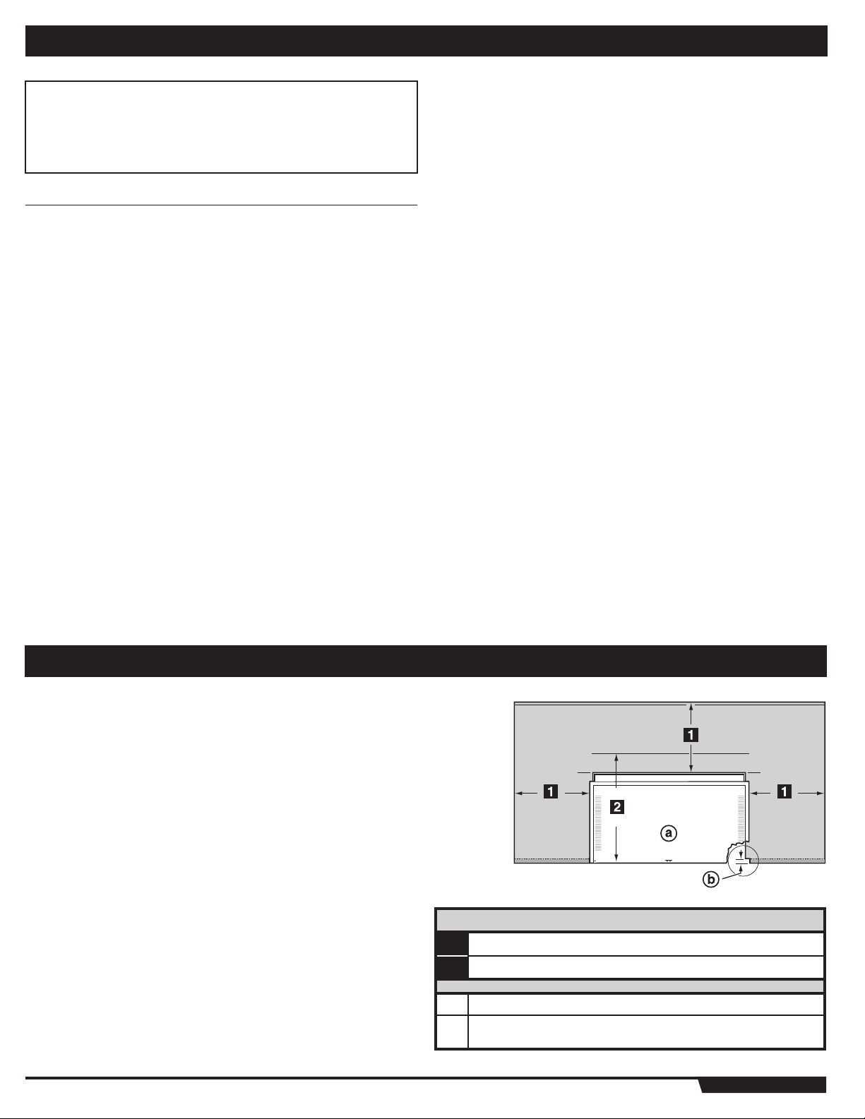
CLEARANCE FROM SURFACES OR STRUCTURES
WARNING: Clearance from any surface or structure is 24
inches (609.6 mm) from the back and sides of the grill.
Refer to “Typical Gas Supply Installation” before starting
installation.
WARNING: The structure, “island”, countertops, and adjacent
work areas for the built-in grill installation must be built from
noncombustible materials only.
NOTE: If you have questions on what materials are considered noncombustible, contact
your local building materials supplier or fire department.
CLEARANCES
24˝ inches (610 mm) Any Surface
1
27˝ inches (685.8 mm) min. for lid clearance
2
Grill Frame
a
Note: For a countertop treatment: Recommended 3/4˝ (19.1 mm)
b
overhang. Notch front edge for frame to fully slide in.
WWW.WEBER.COM
®
Page 3
BUILT-IN CUTOUT DIMENSIONS
3
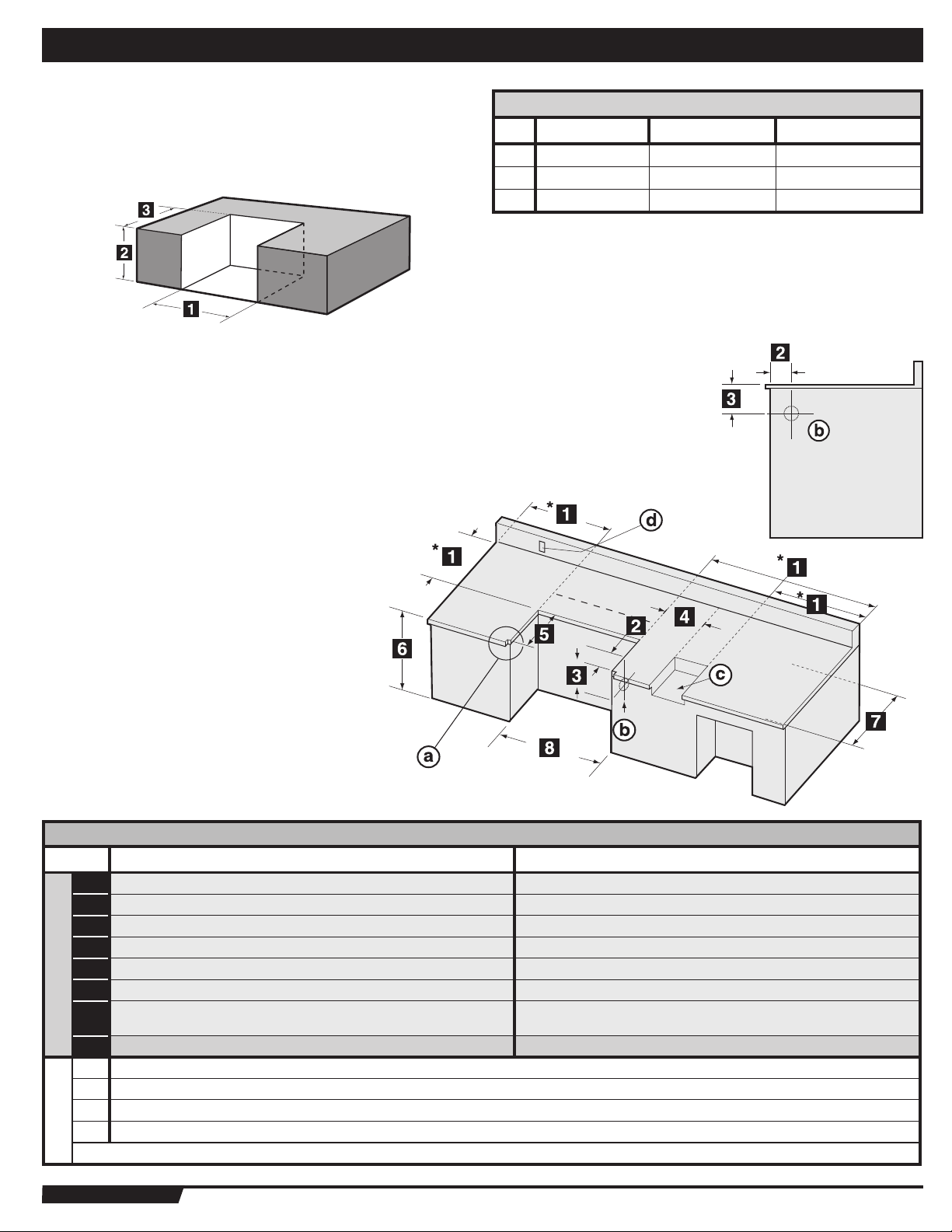
BUILT-IN STRUCTURE CUTOUT DIMENSIONS
ALL DIMENSIONS ARE TO FINISHED SURFACES.
WARNING: All countertop finished surfaces must be
constructed of a noncombustible material.
GENERAL CONSTRUCTION DETAILS
Summit® Built-In unit and all other accessory units should be on site before construction
begins.
All dimensions have a tolerance of plus or minus (+/-) 1/
The grill frame rests directly on the Island Structure top finished surface. Make
sure this surface is level. Do not support the grill from the bottom.
If the supporting structure is going to have an electrical outlet for a
rotisserie, it should be on the left side of the structure.
inch (6.35 mm).
4
BUILT-IN CUTOUT DIMENSIONS
1 30
2 34
3 23˝ (584.2 mm) 23˝ (584.2 mm) +
S-460™ S-660™ TOLERANCES
1
˝ (768.35 mm) 38
/
4
3
/
˝ (873.13 mm) 34
8
1
˝ (971.55 mm) +
/
4
3
/
˝ (873.13 mm) +
8
3
1
1
˝ -
˝ (6.35mm)
/
/
4
4
1
1
/
/
˝ -
˝ (6.35mm)
4
4
1
1
˝ -
˝ (6.35mm)
/
/
4
4
BUILT-IN CUTOUT DIMENSIONS
S-460™ S-660™
1
2
3
4
5
6
DIMENSIONS
7
8
a
Note: For a countertop treatment: Recommended 3/4” (19.1 mm) overhang. Notch front edge for frame to fully slide in.
b
Gas Inlet
c
Side Burner Opening
d
Access for electric on left hand side
* Clearance from any surface or structure is at least 24” (609.6mm) from the back and sides of the grill or side burner.
WWW.WEBER.COM
27” (685.8 mm) minimum distance from front edge of
®
24” minimum* (610 mm) 24” minimum* (610 mm)
4 3/4” (120.65 mm) 4 3/4” (120.65 mm)
6 1/4” (158.75 mm) 6 1/4” (158.75 mm)
10 1/2” (266.7 mm) minimum 10 1/2” (266.7 mm) minimum
23” (584.2 mm) 23” (584.2 mm)
34 3/8” (873.13 mm) 34 3/8” (873.13 mm)
the cutout for open lid clearance
30 1/4” (768.35 mm) Built-In Frame 38 1/4” (971.55 mm) Built-In Frame
27” (685.8 mm) minimum distance from front edge of
the cutout for open lid clearance
Page 4
4
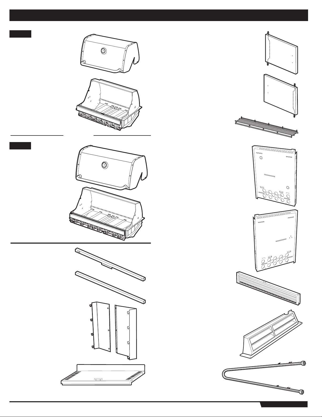
S-460
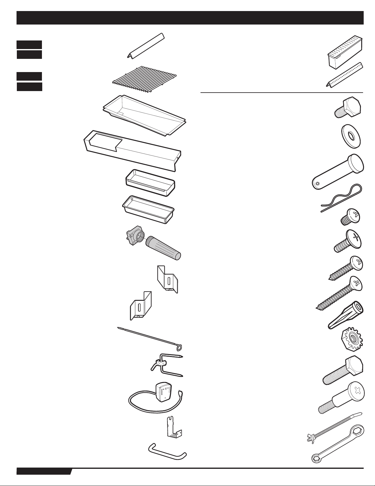
PARTS LIST
™
Lid - 1
Cookbox - 1
™
S-660
Lid - 1
Left Door - 1
Right Door - 1
Warming Rack - 1
OR
Right Enclosure Panel - 1
Cookbox - 1
Front Frame Rail - 1
Rear Frame Rail - 1
Rear Panel Assembly - 1
Left Enclosure Panel - 1
Front Vent Panel - 1
Rear Vent - 1
Bottom Shelf - 1
Corrugated Gas Line - 1
WWW.WEBER.COM
®
Page 5
PARTS LIST
5
Flavorizer® Bars
™
S-460
S-660
Stainless Steel Cooking Grates
S-460
S-660
Collection Tray - 1
Catch-Pan Holder - 1
Catch-Pan - 1
Disposable Drip Pans - 2
- 8
™
- 12
™
- 2
™
- 3
Smoker - 1
5
Smoker Bar - 1
1/2 inch Bolts (¼-20 x 1/2 inch Bolt) - 10
Nylon Washer - 10
Hinge Pin - 2
Hair Pin Cotter - 2
#10-32 x 1/4 inch Steel Screw - 5
Battery Housing - 1
Right Front Vent Clip - 1
Left Front Vent Clip - 1
Rotisserie - 1
Rotisserie Fork - 4
Rotisserie Motor - 1
¼-20 x 1/2 inch Truss Head Screw - 2
#10 Sheet Metal Screw - 3
Flat Head Screw - 2
Plastic Anchors - 5
Keps Nuts (1/4 x 20 Keps Nut) - 2
1 inch Bolt (¼-20 x 1 inch Bolt) - 2
Handle Hardware - 4
Rotisserie Bracket - 1
Handle - 2
WWW.WEBER.COM
Wire Tie - 1
7/16 inch Wrench - 1
®
Page 6
6
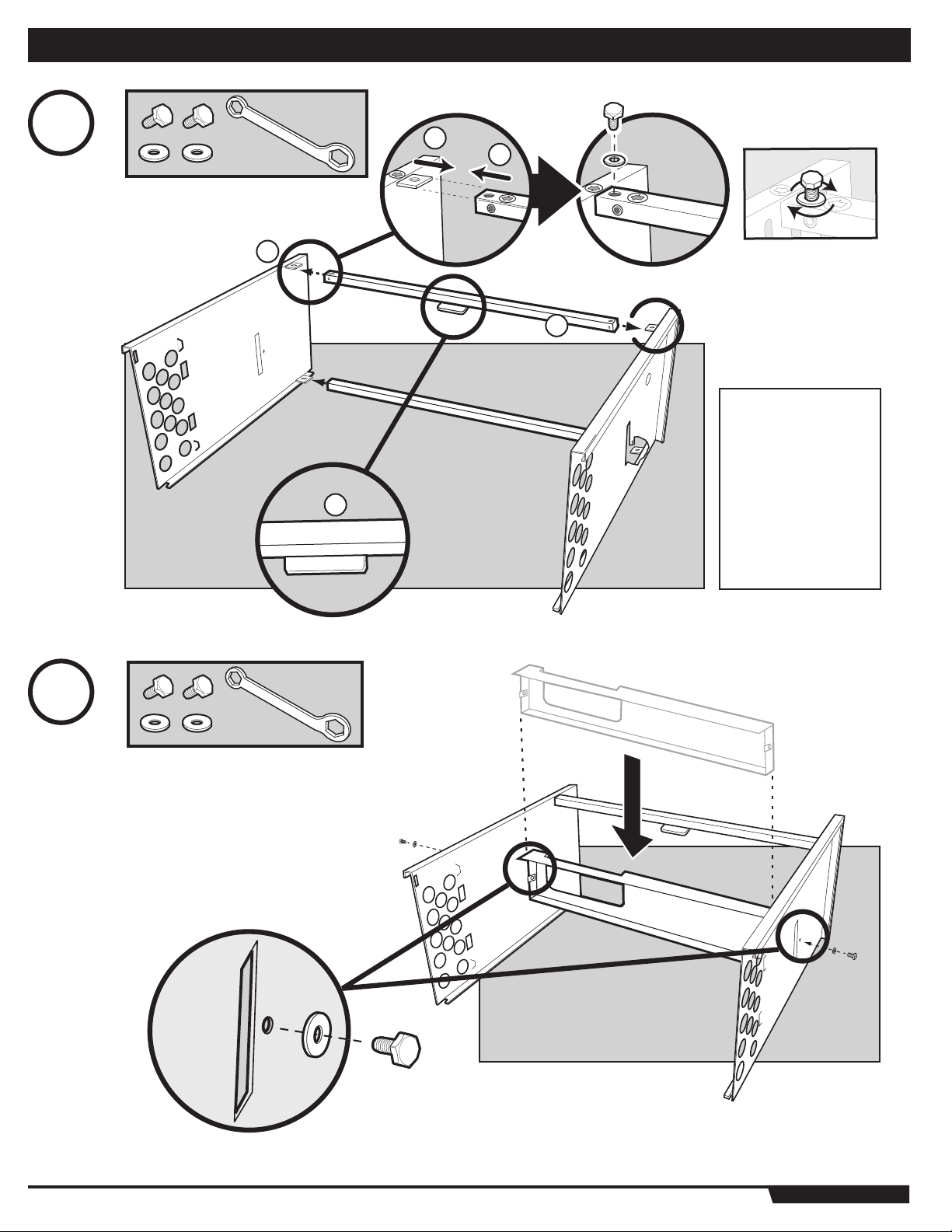
1
1
2
2
3
1
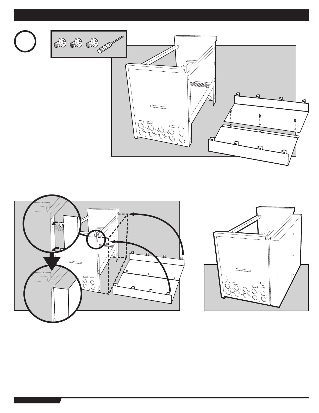
ASSEMBLY
Arrow stickers
on Frame Rail
(1) and Left Side
Panel (2) should
point toward each
other (shown
above). Door Stop
Bracket (3) should
be positioned as
shown (left).
2
WWW.WEBER.COM
®
Page 7
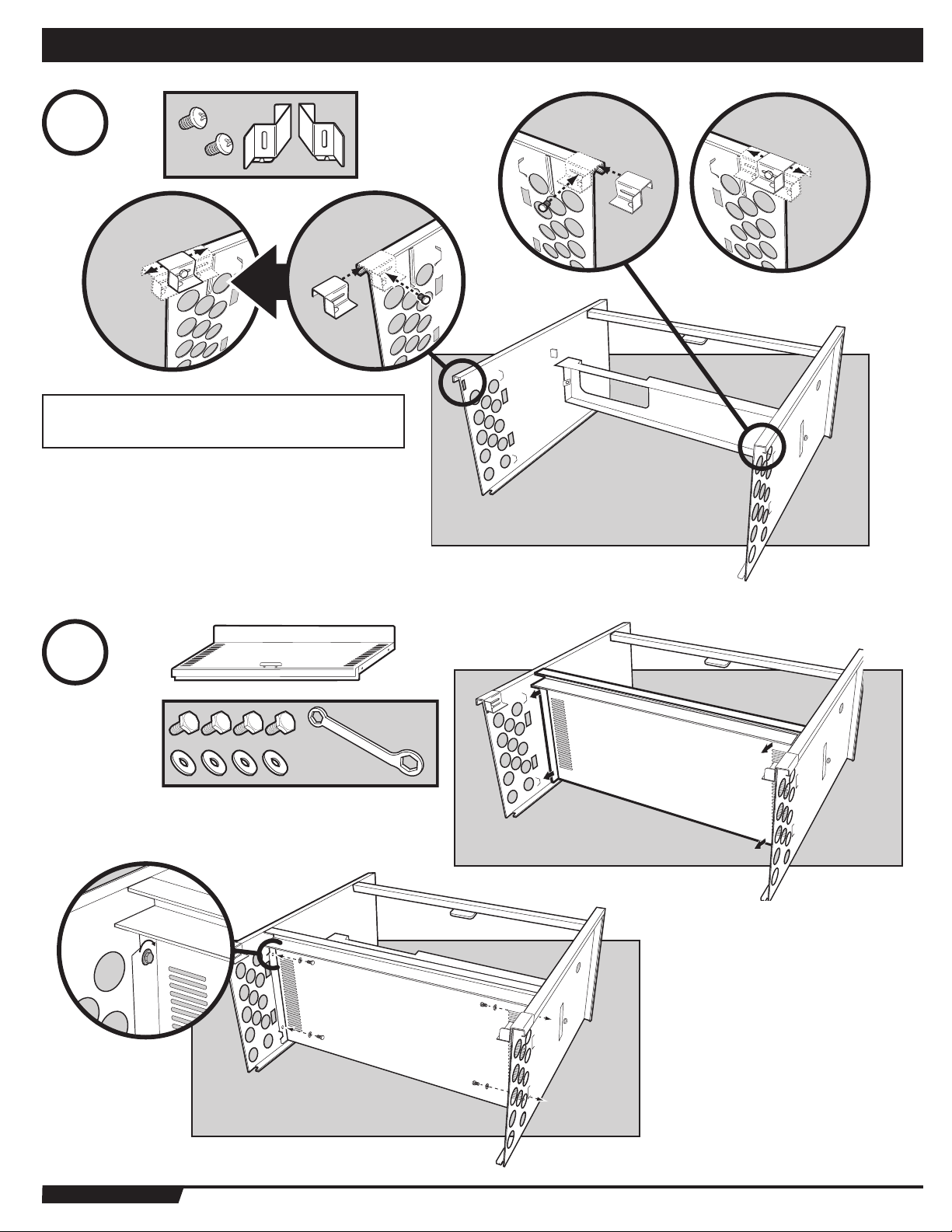
3
ATTENTION! Do not fully tighten screws.
Clips should slide freely when installed.
ASSEMBLY
7
7
4
WWW.WEBER.COM
®
Page 8
8
5
ASSEMBLY
6
Back
WWW.WEBER.COM
®
Page 9
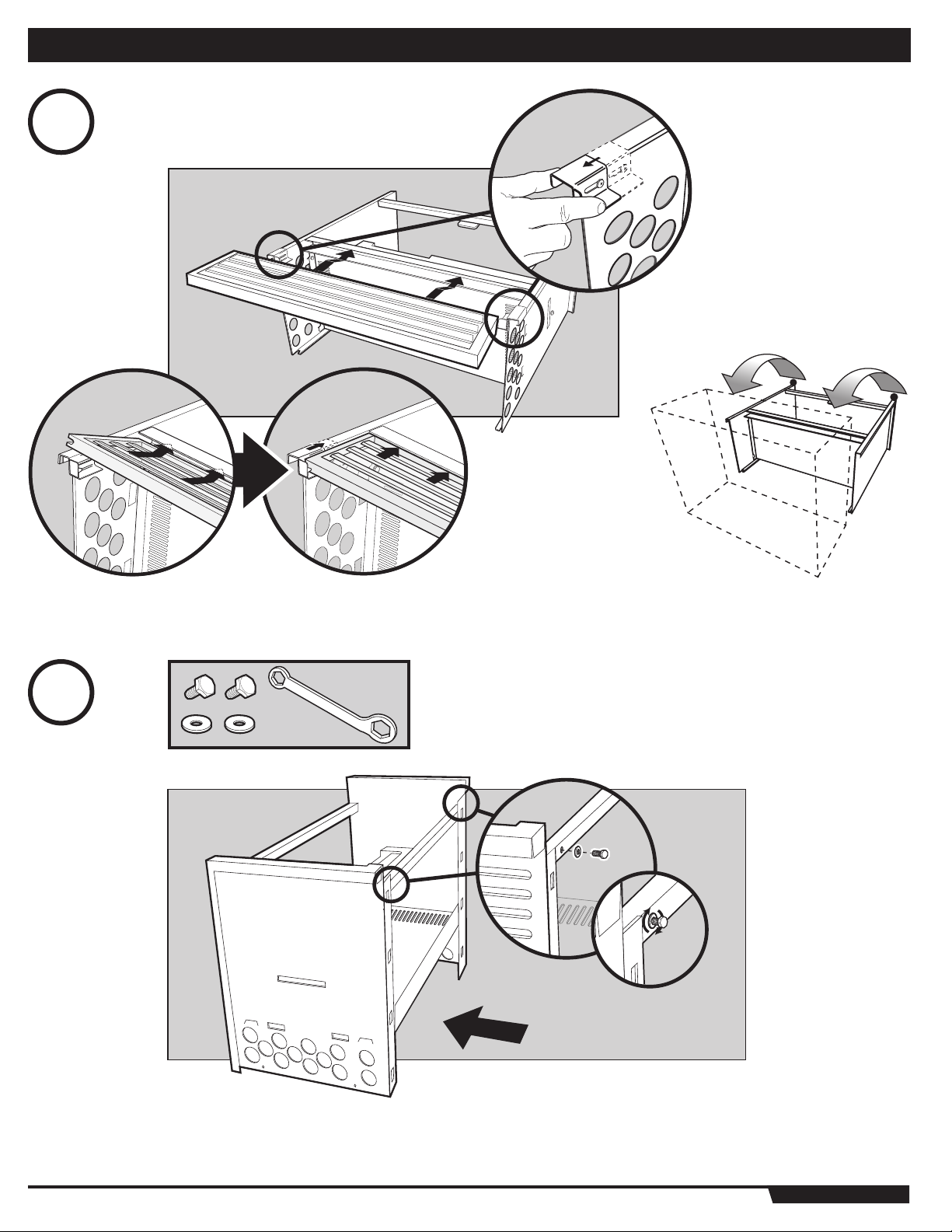
7
ASSEMBLY
9
9
WWW.WEBER.COM
®
Page 10
10
8
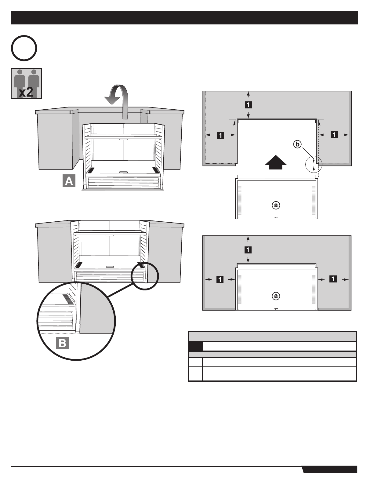
ASSEMBLY
CAUTION: Use two people to lift and install the Summit® Built-In frame assembly.
A) Lift the frame assembly into the “island” structure opening. Make sure the frame is resting level on the finished surface of the structure.
B) Adjust the Front Vent to rest squarely on ground.
CLEARANCES
24" (610 mm) Any Surface
1
Grill Frame
a
Note: For a countertop treatment: Recommended 19.1 mm (3/4˝
b
inch) overhang. Notch front edge for frame to fully slide in.
WWW.WEBER.COM
®
Page 11

9
ASSEMBLY
11
11
1/4" (6.35 mm)
Drill Bit
10
S-460™
A
ATTENTION! Before applying
any silicone sealant make
sure the cookbox is flush with
the front of the grill frame.
A) Apply a bead of silicone sealant (1) around
the perimeter and front edges of the grill that
are in contact with the “island” structure. This
will prevent moisture seepage. The sealant
you use must have a temperature rating
above 120°F (48.8° C).
(1)
S-660™
WWW.WEBER.COM
®
Page 12

12
ASSEMBLY
11
S-460™
F ))#
3 -
1
BATTERY HOUSING WIRING
1 BLACK WIRE
4
3
2 GREEN WIRE
3 RED WIRE
4 RED WIRE
WARNING: Make sure that all control knobs are turned to the OFF
2
position before connecting the gas supply and operating the grill.
D
WWW.WEBER.COM
®
Page 13

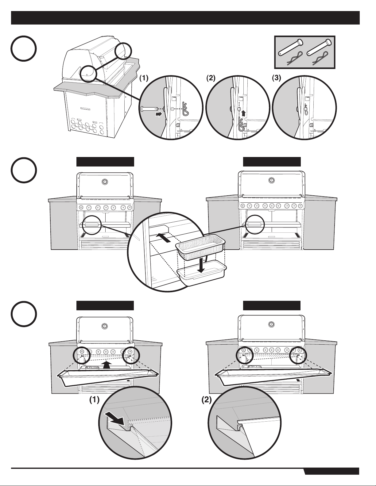
12
ASSEMBLY
Requires 3 “D” alkaline batteries (Included). Use alkaline
batteries only. Do not mix old and new batteries or different types
of batteries (standard, alkaline or rechargeable).
13
13
13
Note: Secure wire to side panel.
(1) (2) (3)
WWW.WEBER.COM
®
Page 14
14
14
15
ASSEMBLY
S-660™S-460™
16
S-660™S-460™
WWW.WEBER.COM
®
Page 15

ASSEMBLY
15
17
A
S-660™S-460™
15
WWW.WEBER.COM
B
Match Holder
C
®
Page 16

16
18
ATTENTION!
Before drilling
any holes for the
rear vent make
sure the cookbox
is flush with the
front of the grill
frame.
ASSEMBLY
1/4" (6.35 mm)
Drill Bit
WWW.WEBER.COM
®
Page 17

ASSEMBLY
17
19
S-660™S-460™
17
20
S-460
™
S-660
™
WWW.WEBER.COM
®
Page 18

18
21
ASSEMBLY
22
S-460
™
S-660
™
S-660™S-460™
WWW.WEBER.COM
®
Page 19

ASSEMBLY
19
23
S-660™S-460™
19
WWW.WEBER.COM
®
Page 20

20
24
S-460
S-660
ASSEMBLY
™
™
WWW.WEBER.COM
®
Page 21

+
+
+
25
AAA
AAA
AAA
S-460
S-660
ASSEMBLY
™
- 1
™
- 2
The Weber Grill Out™ Handle Light has a “Tilt Sensor”: Lid up - ON / Lid Closed - OFF. The power
button (a) activates or deactivates the “Tilt Sensor.” For daytime use, deactivate the sensor by
pressing power button (a).
Requires 3 “AAA” alkaline batteries
(not included)
21
S-460
S-660
21
™
- 2
™
- 4
WWW.WEBER.COM
™
S-660
®
Page 22

22
GAS SUPPLY
BUILT-IN GAS LINE LOCATIONS
Note: Leave an access in the “island” structure for gas supply and regulator service
that is not inside the grill structure. Note: Area should be kept clear of sharp, jagged, or
extremely abrasive surfaces to avoid possible damage to gas supply lines. Exercise
caution when pulling gas lines through built-in structure.
1
(120.65 mm)
2
DIMENSIONS
3
a
b
c
BUILT-IN GAS LINE LOCATIONS
460 660 TOLERANCES
4 3/4˝
6 1/4˝
(158.8 mm)
2 1/2˝
(63.5 mm)
4 3/4˝
(120.65 mm)
6 1/4˝
(158.8 mm)
2 1/2˝
(63.5 mm)
Plan View Left
Side View
Gas Inlet
+1/8˝(
- 1/8˝(
+1/8˝(
- 1/8˝(
+1/8˝(
- 1/8˝(
3.8
3.8
3.8
3.8
3.8
3.8
mm)
mm)
mm)
mm)
mm)
mm)
TYPICAL BULK PROPANE GAS SUPPLY INSTALLATION
We recommend that this installation be done by a LICENSED professional.
GENERAL SPECIFICATIONS FOR PIPING
Note - Contact your local municipality for building codes regulating outdoor gas grill
installations. In absence of Local Codes, you must conform to the latest edition of the
National Fuel Gas Code ANSI Z223.1/NFPA 54, Natural Gas and Propane Installation
Code, CSA B149.1, or Propane Storage and Handling Code, B149.2, or the Standard for
Recreational Vehicles, ANSI A 119.2/NFPA 1192, and CSA Z240 RV Series, Recreational
Vehicle Code, as applicable.
• This grill is designed to operate at 11 inches of water column pressure. An LP in line
regulator may be necessary for this pressure.
CAUTION: If young children are in the area, a locking valve
should be considered.
• Pipe compound should be used which is resistant to the action of liquid propane
gas when gas connections are made.
• The gas connections must be firmly attached to rigid, permanent construction.
Note: The information provided in this manual is general for typical installations. We
cannot cover all possible installation ideas. We recommend, prior to installation, that you
contact your municipality for local building codes and your local fire department for
installation verification.
If you have any questions, contact Customer Service at 1-800-446-1071.
WWW.WEBER.COM
®
Page 23

GAS SUPPLY
23
Tab le
6.2(a)
Nominal
Iron Pipe
Size
(Inches)
1/2 .622 131 90 72 62 55 50 46 42 40 38 33 30 28 26
3/4 .824 273 188 151 129 114 104 95 89 83 79 70 63 58 54
1 1.049 514 353 284 243 215 195 179 167 157 148 131 119 109 102
1 1/4 1.380 1,060 726 583 499 442 400 368 343 322 304 269 244 224 209
1/12 1.610 1,580 1,090 873 747 662 600 552 514 482 455 403 366 336 313
2 2.067 3,050 2,090 1,680 1,440 1,280 1,160 1,060 989 928 877 777 704 648 602
2 1/2 2.469 4,860 3,340 2,680 2,290 2,030 1,840 1,690 1,580 1,480 1,400 1,240 1,120 1,030 960
3 3.068 8,580 5,900 4,740 4,050 3,590 3,260 3,000 2,790 2,610 2,470 2,190 1,980 1,820 1,70 0
4 4.026 17,500 12,000 9,660 8,270 7,330 6,640 6,110 5,680 5,330 5,040 4,460 4,050 3,720 3,460
TEST CONNECTIONS
All connections and joints must be thoroughly tested for leaks in accordance with local
codes and all listed procedures in the latest edition of the National Fuel Gas Code ANSI
Z223.1/NFPA 54, Natural Gas and Propane Installation Code, CSA B149.1, or Propane
Storage and Handling Code, B149.2, or the Standard for Recreational Vehicles, ANSI A
119.2/NFPA 1192, and CSA Z240 RV Series, Recreational Vehicle Code, as applicable.
Actual
ID:
(Inches)
© 2008 National Fire Protection Association, Inc. and International Approval Services - U.S., Inc. All Rights Reserved.
Maximum Capacity of Metallic Pipe in Cubic Feet of Gas per Hour for Gas Pressures of 2 psi or Less and
a Pressure Drop of 0.3 Inch Water Column. (Based on a 0.60 Specific Gravity Gas)
Length of Pipe (Feet)
10 20 30 40 50 60 70 80 90 100 125 150 175 200
DANGER
Do not use an open flame to check for gas leaks. Be sure
there are no sparks or open flames in the area while you
check for gas leaks. This will result in a fire or explosion
which can cause serious bodily injury or death, and damage
to property.
23
WWW.WEBER.COM
®
Page 24

24
GAS SUPPLY
TYPICAL 20 LP PROPANE GAS SUPPLY INSTALLATION
The remote tank enclosure kit provide with you grill shall be used for installations using a
20 lb LP cylinder, mounted in an “island” structure.
The remote tank enclosure shall house the included hose and regulator assembly and
gas connections, the tank bracket and the fuel scale for connecting a remote mounted
LP cylinder to the Summit
part of the CSA listed Summit® Built-In gas grill.
A properly installed tank enclosure meets the requirements for venting, tank retention
and separation of the LP cylinder from a heat source as outlined in the ANSI Standard for
Outdoor Cooking Gas Appliances, Z21.58/CSA 1.6 for LP enclosures.
You need to hire a licensed contractor or licensed plumber and they need to follow the
requirements described in the ANSI Standard for Outdoor Cooking Gas Appliances,
Z21.58/CSA 1.6 for LP enclosures.
The requirements described in the Standard for Outdoor Cooking Gas Appliances,
Z21.58/CSA 1.6. are as follows;
A remote enclosure for an LP gas cylinder shall be ventilated by openings at both the
upper and lower levels of the cylinder. This shall be accomplished by one of the following:
A) One side of the remote LP cylinder enclosure shall be completely open; or
B) If the remote LP cylinder enclosure is designed to have four sides, a top and a bottom,
ventilation is required for the remote LP cylinder enclosure;
1) There should be at least two ventilation openings, (a hole or group of
holes, for the purpose of ventilation) in the sidewalls of the island structure.
The openings should be located within 5 inches (127mm) of the top of the
enclosure. The ventilation openings should be equally sized and spaced at a
minimum of 90 degrees, and be unobstructed. The openings shall have a total
free open area of not less than 20 square inches. (This relates to 1 square
inch of ventilation area, per pound of stored fuel capacity).
2) Ventilation openings (a hole or group of holes, for the purpose of ventilation)
should be provided at floor level. The ventilation openings should have a total
free area of not less than 10 square inches. (This relates to 1/2 square inch of
ventilation area, per pound of stored fuel capacity). There should be at least
two ventilation openings if the ventilation openings at floor level are in the
sidewall. The ventilation openings should be within 5 inches (127mm) of the
floor. The ventilation openings should be of equal size and be spaced at a
minimum of 90 degrees, and should be unobstructed.
3) The minimum size of the ventilation hole (s) should not be less than 1/4 inch.
4) The ventilation openings in the sidewalls should not allow venting into
the empty or “hollow” area of the “island”. If a gas leak should occur or
the LP cylinder should vent in the LP cylinder enclosure, the gas should
not be allowed to vent or migrate into the empty or “hollow” area of the
“island”. Ventilation openings in the sidewalls of the enclosure should only
communicate with the outside of the “island” structure, so that the gas can
dissipate outside of the “island” structure.
C) If the remote LP cylinder enclosure has four sides, a top and a bottom, and is intended
for installation in a built-in “island” enclosure;
1) At least one ventilation opening (a hole or group of holes, for the purpose
of ventilation) needs to be on one side of the enclosure that communicates
with the outside of the “island” structure. If a gas leak should occur or the
LP cylinder should vent in the LP cylinder enclosure, the gas should not
be allowed to vent or migrate into the empty or “hollow” area of the “island”.
Ventilation openings should only communicate with the outside of the “island”
structure, so that the gas can dissipate outside of the “island” structure. The
ventilation opening should be located within 5 inches (127mm) of the top of
the enclosure, and should have a total free area of 20 square inches. (This
relates to 1 square inch of ventilation area, per pound of stored fuel).
2) At least one ventilation opening (a hole or group of holes, for the purpose of
ventilation) needs to be on one side of the enclosure that communicates with
the outside of the “island” structure, at the bottom. If a gas leak should occur
or the LP cylinder should vent in the LP cylinder enclosure, the gas should
not be allowed to vent or migrate into the empty or “hollow” area of the “island”.
Ventilation openings should only communicate with the outside of the “island”
structure, so that the gas can dissipate outside of the “island” structure. The
ventilation opening should be located within 5 inches (127mm) of the bottom
of the enclosure, and should have a total free area of 10 square inches. (This
relates to 1/4 square inch of ventilation area, per pound of stored fuel).
3) The minimum size of the ventilation hole (s) should not be less than 1/4 inch
(6.35mm).
®
Built-In gas grill. The hose and regulator is listed as a required
D) The remote LP cylinder enclosure should be constructed with non-combustible
materials. The remote LP cylinder enclosure should isolate the LP cylinder from the
burner compartment, so that it provides shielding from radiation, be a flame barrier
and provide protection from foreign material such as hot drippings.
E) There should be a minimum of 2 inches (50.8mm) between the ground and the floor of
the remote LP cylinder enclosure.
F) The LP cylinder valve should be readily accessible for hand operation. A door on the
remote LP cylinder enclosure to gain access to the LP cylinder valve is acceptable,
provided it is non-locking and can be opened without the use of tools.
DANGER
Use of any other hose and regulator assembly could be
dangerous, and may not provide adequate gas supply to
the Summit® Built-In gas grill, and could result in a fire or an
explosion causing serious bodily injury or death, and damage
to property.
DANGER
Failure to build a remote LP cylinder enclosure for a 20 lb
cylinder following the requirements for ventilation, cylinder
retention and separation of the LP cylinder from a heat
source, listed in the ANSI Standard for Outdoor Cooking Gas
Appliances, ANSI Z21.58 CSA 1.6, could be dangerous, and
could result in a fire or an explosion causing serious bodily
injury or death and damage to property.
If you do not follow the DANGER statements exactly, the Warranty on the Summit® Built-In
gas grill will be voided.
WWW.WEBER.COM
®
Page 25

BUILT-IN TANK ENCLOSURE INSTRUCTIONS
25
25
OPERATING
WARNING: Only use the Weber® Tank Enclosure Kit outdoors
in a well-ventilated area. Do not use in a garage, building,
breezeway or any other enclosed area.
WARNING: Your Weber® Tank Enclosure Kit shall not be used
under an unprotected combustible roof or overhang.
WARNING: Your Weber® Tank Enclosure Kit is not intended to
be installed in or on recreational vehicles and/or boats.
WARNING: Keep any electrical supply cord and the fuel
supply hose away from any heated surface.
WARNING: Never store an extra (spare) LP cylinder under or
near the Weber® gas barbecue.
WARNING: Keep the ventilation openings of the cylinder
enclosure free and clear of debris.
WARNING: Turn off the gas at the LP gas supply cylinder
when the outdoor cooking gas appliance is not in use.
WARNING: Never store an outdoor cooking gas appliance
indoors unless the LP cylinder is disconnected and removed
from the outdoor cooking gas appliance.
WARNING: LP Cylinders must be stored outdoors out of
the reach of children and must not be stored in a building,
garage, or any other enclosed area.
WARNING: The LP pressure regulator and hose assembly
supplied with the Weber
Replacement LP pressure regulators and hoses must be
obtained from Weber-Stephen Product Co.
®
Tank Enclosure Kit must be used.
WWW.WEBER.COM
®
Page 26

26
BUILT-IN TANK ENCLOSURE INSTRUCTIONS
DANGER
Use of any other hose and regulator assembly could be
dangerous, and may not provide adequate gas supply to
the Summit
®
Built-In gas grill, and could result in a fire or an
explosion causing serious bodily injury or death and damage
to property.
DANGER
Failure to build a LP cylinder enclosure for a 20 lb cylinder
following the requirements for ventilation, cylinder retention
and separation of the LP cylinder from a heat source, listed in
the ANSI Standard for Outdoor Cooking Gas Appliances, ANSI
Z21.58 CSA 1.6, could be dangerous, and could result in a fire
or an explosion causing serious bodily injury or death and
damage to property.
If you do not follow the DANGER statements exactly, the Warranty on the Summit®
Built-In gas grill will be voided.
LOCATING YOUR LP TANK ENCLOSURE KIT
When determining a suitable location for your LP Tank Enclosure Kit installation, give
attention to concerns such as proximity to traffic paths, and keeping any gas supply
lines as short as possible. Never locate the Summit® LP Tank Enclosure Kit in a garage,
breezeway, shed, under an unprotected overhang, or other enclosed area. Locate the LP
Tank Enclosure Kit and structure so there is enough room to safely evacuate the area in
case of a fire.
c
1
b
1 1
b
a
ENCLOSURE CHART
24˝ inches (610 mm) Any Surface
1
LP Tank Enclosure
a
Any Surface
b
Non-Combustible Surface
c
CLEARANCE FROM COMBUSTIBLE SURFACES OR
STRUCTURES
WARNING: Clearance from the outside walls of the sides
and back of the LP Tank Enclosure must be a minimum of
24" (60.96cm) any surface. Refer to “Typical Gas Supply
Installation” before starting installation.
WARNING: The structure, “island” counter tops and adjacent
work areas for the LP Tank Enclosure must be built from
noncombustible materials only.
NOTE: If you have questions on what materials are considered noncombustible, contact
you local building supplier or fire department.
WWW.WEBER.COM
®
Page 27

PARTS LIST / ASSEMBLY
27
PARTS LIST
Hose and regulator - 1
Tank stand - 1
1
4
8
4
27
Tank stand base - 1
Tank Scale - 1
1/4-20 nut - 6
Nylon washer - 12
1/4-20 x 1/2” bolt - 6
Cylinder glide - 2
2
2
4
WWW.WEBER.COM
1/2” Flare Gasket - 2
2
3/8” Flare Gasket - 2
®
2
Page 28

28
MOUNTING THE LP TANK BRACKET
Mount the LP tank bracket to the right hand side of the enclosure opening using non corrosive hardware. Mounting holes are provided on the sides and bottom of your LP tank bracket.
Be sure to mount the bracket securley to the enclosure before use.
MOUNTING HARDWARE NOT INCLUDED.
MOUNTING THE LP HOSE AND REGULATOR
Securley mount the hose and regulator bracket to the top of the built-in tank enclosure using non corrosive hardware.
ASSEMBLY
3
MOUNTING HARDWARE NOT INCLUDED.
LP TANK ENCLOSURE GAS LINE LOCATIONS
Area should be kept clear of sharp, jagged, or extremely abrasive surfaces to avoid possible damage to gas supply lines. Exercise caution when pulling gas lines through built-in
structure.
4
WWW.WEBER.COM
®
Page 29

GAS SUPPLY
29
CONNECT GAS SUPPLY
A 58 inch (147.32 cm) corrugated gas line is supplied with the grill. This line needs to pass
through the gas inlet opening to the main gas supply.
1) Connect the corrugated gas line to the manifold located on the right hand side of grill
under the control panel. Use the 1/2” flared gasket (1) to ensure proper seal.
Note: 1/2” flared gaskets are included in the Summit
with your grill.
The corrugated line passes through the “Island Structure” cavity to the hose and regulator
connection inside the tank enclosure. (Shown in illustration)
2) Uncap one flare fitting from the 90º Connection on the regulator hose located inside
the tank enclosure.
3) Use the 1/2 (12.7 mm) inch flared gasket to ensure proper seal.
NOTE: Only use the 3/8 inch (9.53 mm) flared gasket if you are installing the optional side
burner.
4) Connect the corrugated gas line to the 90º Connection.
®
Built-In tank Enclosure Kit included
29
A
CONNECTION CHART
Top View
A
Typical tank cabinet or tank enclosure location
B
Side View
C
Top of Box
D
Back of Box
E
Corrugated Gas Line to Manifold
i
90° fitting
ii
1/2” (12.7 mm) Flared Gasket
iv
Cap (Optional Side Burner)
v
B
i
E
iv
v
C
D
ii
WWW.WEBER.COM
®
Page 30

30
GAS SUPPLY
VENTILATION
WARNING: Ventillation holes must be provided in the
structure at the top and bottom to provide ventilation in the
event of a gas leak.
Ventilation holes can be located in a low visibility area and should be protected by
screening material to prevent rodents and insects from entering the structure. Air holes
will also help dry moisture.
Note: These drawings are only a reference.
• Cross ventilation must be incorporated in the supporting structure. We recommend
a minimum of 100 square inches (254 square cm )of venting per side.
• Vents should be on two sides of the structure.
• The above drawings are for reference only.
• Location of the vents should be from the center, outward.
• Locate the vents at both the bottom of the structure and at the top of the structure.
• The bottom vents should be as close to ground level as possible. Make sure the
vent area is not blocked by interior supports of the structure.
• We recommend vents with screens.
• Access doors to the structure are not considered vents.
• Clean the vents periodically.
DANGER: Failure to follow recommended minimum venting
instructions can cause gas to collect in the structure in the
event of a gas leak. This may result in a fire or an explosion
which can cause serious bodily injury or death, and damage
to property.
WWW.WEBER.COM
®
Page 31

NOTES
31
31
Page 32

ATTENTION: This product has been safety tested and is only certified for use in a specific country. Refer to country designation
located on outer carton.
These parts may be gas carrying or gas burning components. Please contact Weber-Stephen Products Co., Customer Service Department for genuine Weber-Stephen
Products Co. replacement part(s) information.
WARNING: Do not attempt to make any repair to gas carrying, gas burning, igniter components or structural components
without contacting Weber-Stephen Products Co., Customer Service Department. Your actions, if you fail to follow this Product
Warning, may cause a fire, an explosion, or structural failure resulting in serious personal injury or death as well as damage to
property.
WEBER-STEPHEN PRODUCTS CO.
www.weber.com
©2009 The following trademarks are registered in the name of Weber-Stephen Products Co., an Illinois corporation, located at 200 East Daniels Road, Palatine, Illinois 60067 U.S.A.
Australia; Smokey Joe, Weber, Kettle Silhouette
tion, Botswana; Weber, Canada; Smokey Joe, Genesis, China; Kettle Silhouette
Smokey Joe, Weber, One-Touch, Germany; Smokey Joe, Weber, One-Touch, Greece; Smokey Joe, Ireland; Kettle Silhouette
Joe, Weber, Korea; Smokey Joe, Weber, New Zealand; Weber, Smokey Joe, Nigeria; Weber, Norway; Smokey Joe, Weber, Portugal; Weber, South Africa: Smokey Joe, Weber, Kettle
Configuration, Spain; Smokey Joe, Weber, Sweden; Kettle Silhouette
One-Touch, U.S.A..; Kettle Configuration, Kettle Silhouette
Crossover, Flamgo, Performer, Rapidfire, Tuck ‘N Carry, Jumbo Joe, Bar-B-Kettle, Master-Touch, Spirit, Grill Out, Summit, Platinum, 1-800-Grill-Out, Ranch, Matchless Flame, Zimbabwe;
Weber, Kettle Configuration, Kettle Silhouette
, Genesis, Austria; Kettle Silhouette , Smokey Joe, Weber, Benelux; Kettle Silhouette , Smokey Joe, Weber, Compact Grill Configura-
, Smokey Joe, Switzerland; Kettle Silhouette , Smokey Joe, Weber, United Kingdom; Smokey Joe, Weber, Weber
, Smokey Joe, Weber, One-Touch, Firespice, Go-Anywhere, U.S.A.;Kettle Configuration, Kettle Silhouette, Genesis, Flavorizer,
.
, Denmark; Kettle Silhouette , Smokey Joe, Weber, Finland; Smokey Joe, France; Kettle Silhouette ,
®
, Smokey Joe, Italy; Smokey Joe, Weber, Japan; Smokey
 Loading...