

Page 1
WEBECO
Installation & Operation
Vertical
Model
Manual
of
Steam
B-C-H
for
Sterilizer
Page 2
1610e
No.
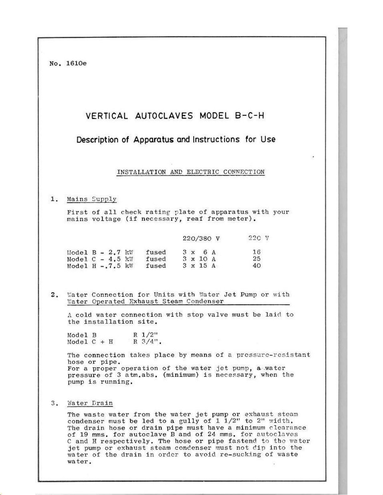
VERTICAL
Description
Mains
First
mains
Model B -
Model C -
Model H -.7.5 fused
ater
Water
Supply
of
all
voltage
2,7
4,5
Connection
Operated
AUTOCLAVES
of
Apparatus
INSTALLATION
check
(if
rating
necessary,
fused
fused
for
Units
Exhaust
Steam
and
Instructions
AND
ELECTRIC
plate
reaf from
220/380
3x
3 x 10
3 x 15
with
Condenser
MODEL
CONNECTION
of
apparatus
meter).
V
SA
À
A
Water
Jet
B-C-H
for
with
220
16
25
40
Pump
Use
Y
or
your
with
A
cold
the
Model
Model C +
The
hose
For a proper
pressure
pump
Water
The
condenser
The
of 19
C
and H respectively.
jet
water
water,
water
installation
B R
connection
or
pipe.
is
running.
Drain
waste water
drain
mms,
pump
of
connection
H в
takes
operation
of 3 atm.abs.
must
hose
or
the
be
or
for
autoclave B and
exhaust
drain
site.
1/2"
3/4".
from
led
drain
with stop
place
of
(minimum)
the
water
to a gully
pipe
The
steam
in
order
valve
by
means
the
water
is
jet
of 1 1/2"
must
hose
concenser
to
have a minimum
of
24
or
pipe
avoid
must
of a pressure-resistant
jet
pump, a water
necessary,
pump
or
mms,
fastend
must
re-sucking
be
when
exhaust
to
2"
for
autoclaves
to
not dip
laid
of
to
the
steam
width,
clearance
tho
water
into
the
waste
Page 3
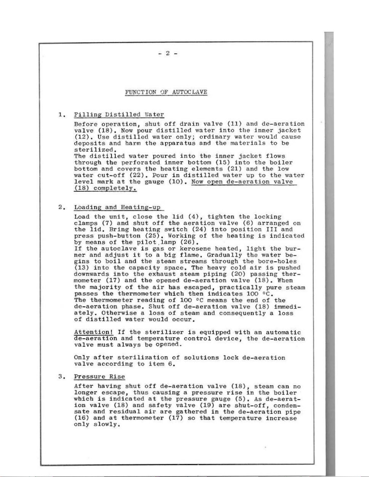
Filling
Before
valve
(12).
deposits
sterilized,
The
through
bottom
water
level
(18)
Loading
Load
clamps
the
press
by
means
If
the
ner and
gins
(13)
downwards
mometer
the
passes
The
de-aeration
ately.
of
distilled
Distilled
operation,
(18), Now
Use
and
distilled
the
and
cut-off
mark
completely.
and
the
unit,
(7)
lid,
majority
thermometer
Bring
push-button
of
autoclave
adjust
to
boil
into
(17)
the
Otherwise a loss
FUNCTION
Water
shut
pour
distilled
harm
water
perforated
covers
(22).
at
the
Heating-up
close
and
shut
heating
the
it
and
the
capacity
into
the
and
of
thermometer
phase,
water would
water
the
poured
the
Pour
gauge
off the
(25),
pilot
is
gas
to a big
the
exhaust
the
the
air has
reading
Shut
OF
AUTOCLAVE
off
drain
distilled
only;
apparatus
inner
heating
in
(10).
the lid (4),
switch
Working
lamp
or
steam
space.
opened
which
of
off
of
occur,
water
ordinary
and the
into
(26).
kerosene
flame,
streams
steam
100
steam
the
bottom
elements
distilled
Now
aeration
(24)
of
The
de-aeration
escaped,
then
°C
de-aeration
valve
open
tighten
Gradually
heavy
piping
indicates
means
and
(11) and
into
inner
(15)
valve
into
the
heated,
through
practically
consequently a loss
the
water
materials
jacket
into
(21) and the low
water
de-aeration
the
(6)
position
heating
the
cold
(20)
valve
the
valve
de-aeration
inner
would
the
up
to
locking
arranged
is
light
the
water
bore-holes
air
passing
(18),
100
°C.
end
of
(18)
jacket
cause
to
be
flows
boiler
the
water
valve
on
III
and
indicated
the
bur-
be-
is
pushed
ther-
When
pure
steam
the
immedi-
Attention!
de-aeration
valve
Only
valve
Pressure
3.
After
longer
which
ion
sate
(16)
only
must
after
according
having
is
valve
and
and
slowly.
If
the
and
always
sterilization
Rise
shut
escape,
indicated
(18)
residual
at
thus
and
thermometer
temperature
to
sterilizer
be
opened.
item
off
at
safety
air
6.
de-aeration
causing a pressure
the
are
(17)
is
equipped
control
of
solutions
pressure
valve
gathered
so
(19)
that
valve
with
device,
lock
rise
gauge
are
in
the
temperature
the
de-aeration
(18),
in
(5),
shut-off,
de-aeration
an
automatic
de-aeration
steam
the
As
can
boiler
de-aerat-
conden-
pipe
increase
no
Page 4
At
the
moment
safety
control.
condensate
and
Now
sterilization
(hen
attained,
II.
safety
With
a
little
valve
The
safety
the
thermometer
the
temperature
Thus
valve.
gas
not
or
bit.
when
(19)
steam
and
residual
valve
the
kerosene
(19)
temperature
heating
too
much
the
pressure
is
attained,
in
excess
air
into
reading
needed
switch
steam
heated
set
by
the
the
safety
is
released
gathered
the
exhaust
increases
corresponding
for
sterilization
may
wiîl
autoclave,
at
very
be
brought
be
released
thermometer
steam
to
throttle
weight
valve
and
pushes
piping
quickly
the
has
into
through
of
the
begins
pressure.
been
position
the
to
out
(17)
(20).
to
the
the
flame
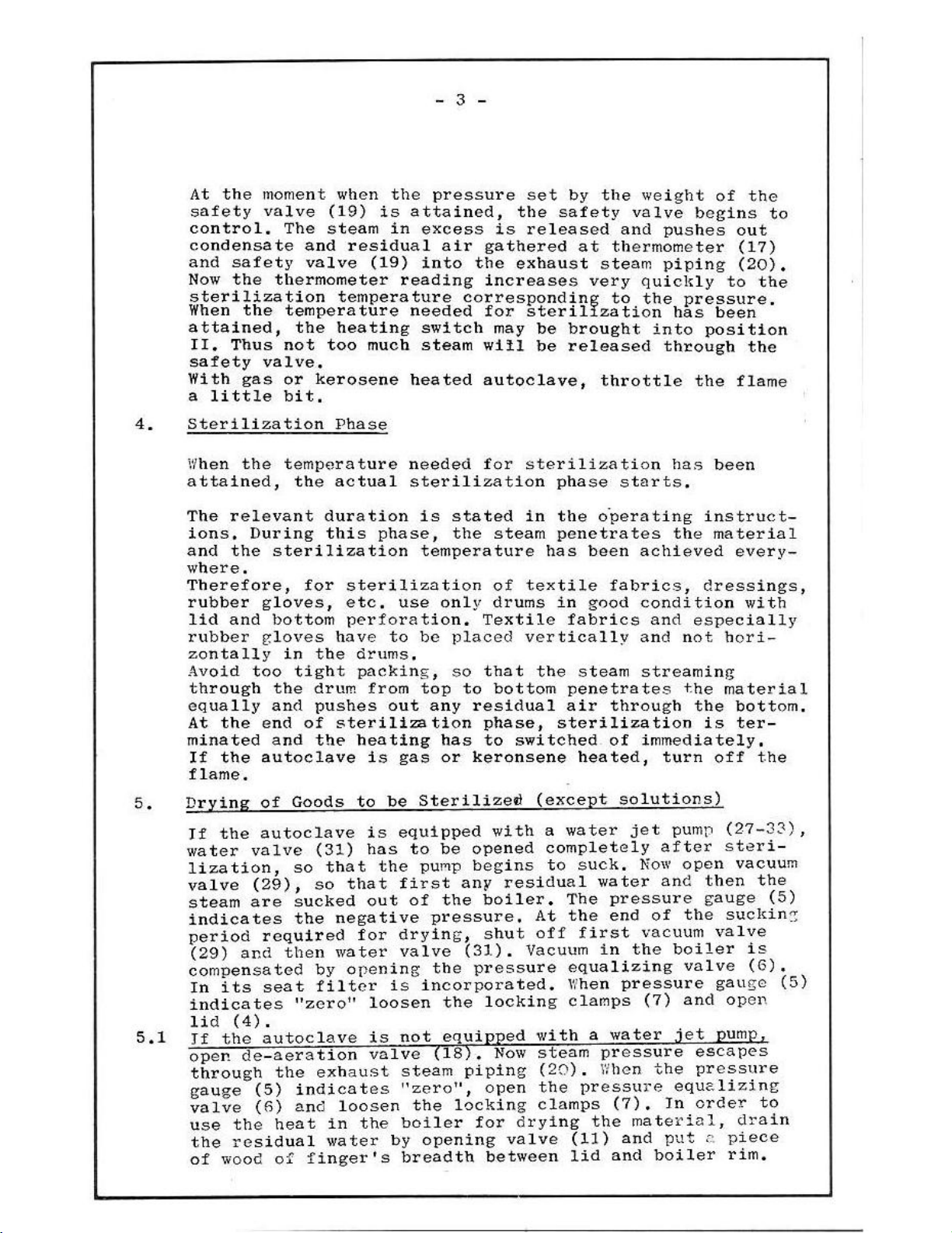
Sterilization
When
attained,
The
ions,
and
where,
Therefore,
rubber
lid
rubber gloves
zontally
Avoid
through
equally
At
minated
If
flame.
Drying
Jf
water
lization,
valve
steam
indicates
period
(29)
compensated
In
indicates
lid
TE
open
through
gauge
valve
use
the
of
the
temperature
the
relevant
During
the
sterilization
gloves,
and
bottom
in
too
tight
the
and
the end
and the
the
autoclave
Goods
of
autoclave
the
valve
so
(29),
sucked
are
the
required
then
and
seat
its
"zero"
(4).
autoclave
the
de-aeration
the
indicates
(5)
and
(6)
heat
the
residual
wood
of
duration
this
for
the
drum
pushes
of
(31)
that
so
by
filter
exhaust
in
water
finger's
Phase
needed
actual
sterilization
etc.
perforation.
have
drums,
packing,
sterilization
heating
to
that
negative
for
water
opening
loosen
the
sterilization
is
phase,
temperature
use
to
be
from
is
is
has
out
loosen
is
valve
top
out
any
gas
Sterilized
be
equipped
to
pump
the
first
of
pressure.
drying,
valve
the
incorporated.
is
not
(18),
steam
"zero",
the
boiler
opening
by
breadth
for
stated
the
only
Textile
placed
so
that
to
residual
phase,
has
to
or
keronsene
opened
be
begins
any
boiler.
the
shut
(31).
pressure
locking
the
equipped
piping
open
locking
for
sterilization
phase
in
the
steam
of
drums
bottom
with
residual
Now
valve
between
penetrates
has
textile
in
fabrics
vertically
the
penetrates
air
sterilization
switched
(except
water
a
completely
to
The
the
At
off
Vacuum
equalizing
When
clamps
with
steam
(20).
the
clamps
drying
(11)
lid
starts,
operating
been
good
steam
heated,
suck.
first
a
pressure
the
achieved
fabrics,
condition
and
and
streaming
through
of
immediately.
turn
solutions)
jet
after
Now
water
pressure
end
in
water
pressure
When
(7),
and
and
of
vacuum
the
pressure
(7)
the
material,
and
boiler
has
been
instruct-
the
material
every-
dressings,
with
especially
not
hori-
the
material
the
bottom,
is
ter-
off
the
pump
boiler
jet
equelizing
In
put
(27-33),
steri-
open
the
valve
and
vacuum
then
gauge
sucking
valve
is
(6).
gaugo
open
pump
escapes
pressure
order
drain
piece
©
rim.
the
to
(5)
(5)
Page 5
små
mm
6.
Cooling
of
Solutions
after
Sterilization
After
do
not
decreases
apparatus,
the
clamps
be
left
7.
Setting
Pressure
trolled
valve,
valve
On
request,
The
are
safety
Attention!
Tf
the
device
thermometer
sterilization
boil
pressure
(7).
As
weight
requisite
automatically
valve
sterilizer
the
over
gradually
When
in
the
the
and
by
means
standard
weights
weights
requisite
pressure
equalizing
To
cool
opened
Sterilization
thus
for
there
sterilization
weights.
(37).
and
of
a
shut
corresponding
down
the
the
supply,
working
are
for
for
kept
is
off
all
bottles
valve
autoclave
temperature
weight
available:
1.0
0,5
constant
equipped
temperature
cannot
gauge
completely,
Pressure
the
pressure
atm.abs. = 120
atm,abs, = 110
temperatures
valves
to
(5)
indicates
(6)
and
for
for
in
the
autoclave
by
using
with a temperature
must
sc
that
burst,
the
loosen
the
some
sterilization
body
of
be
Now
cooling-down
solutions
time.
of
is
2.1
atm.abs.
°C
°C.
(refer
the
set
solutions
the
"zero",
the
the
equipped
to
corresponding
at
the
locking
control
pressure
of
the
open
should
are
con-
safety
with
=
134%,
table)
contact
a
The
requisite
meter,
The
ture,
Timer
temperature,
rilization
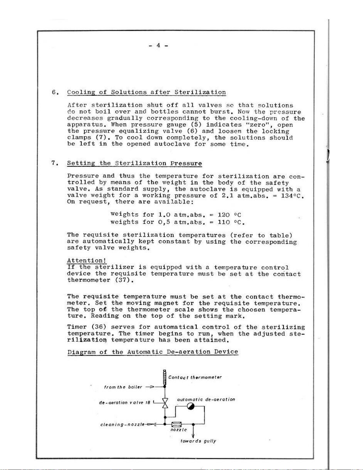
Diagram
Set the
top
of
Reading
(36)
of
from
de-aeration
creaning-nozzle-
temperature
moving magnet
the
thermometer
on
the
serves
The
temperature
the
the boiler
for
timer
Automatic
valve
must
scale shows
top
of
the
automatical
begins
has
been
De-aeration
Contact
>
18
automatic
a
nozzle
towards
be
set
for the
setting
to
attained.
thermometer
requisite
control
run,
Device
de-aeration
gully
at
the
the
mark,
when
contact
temperature,
choosen
of
the
the
adjusted
thermo-
tempera-
sterilizing
ste-
Page 6

If
during
at
the
(see
screwed,
with a cannula
zle
After
inserted
nozzle.
diagram)
can
the
contact
this
also
having
and
operating
thermometer,
has
to
nozzle
or a corresponding
be
unscrewed
been
tightened,
cleansed
period,
then
be
cleansed.
of
1.0
mms.
with a screwdriver,
thoroughly,
The
unit
the
temperature
the
flow
After
in Y should
wire,
does
the
If
the
not
nozzle
operate
is
not
of
the
plug
necessary,
nozzle
be
pushed
has
been
the
must
without
reached
device
un-
through
noz-
be
re-
this
LA
(8
N
(a
TEMPERATURE
CONTACT
AUTOMATIC
Temperature
contact
thermometer
DIAGRAM
or
CONTROL
WITH
THERMOMETER
AND
DE-AERATION
contml
by
DEVICE
DEVICE
means
x
iw’
of
The
de-aeration
ways
sidual
and
When
aerator
via the
When
attained,
(37)
The
and
ATTENTION!
aeration
solutions
opened
air
in
the
flow
temperature
(38)
flow
the
set
the
regulates
steam
must
escapes
be
By
valve
do
valve
until
nozzle
shut
nozzle
temperature
drained
not
the end
the
capacity
(39),
of
abt.
off
(39).
timer
the
the
(18)
(36)
heating
via the
by
sterilization
at
boil
(18)
automatically
over,
must
of
space
100
at
runs
of
nozzle
means
once
never
the
sterilization
escapes
°C
has
contact
down
the
unit
(39)
of a hose
of
after
steriliaztion,
been
and the
thermometer
and
solutions
be
shut,
via the
attained,
the
automatically.
into
or
piping.
it
phase,
de-aerator
steam
(37)
contact
the
water
shut-off
so
remains
escapes
ál-
The re-
(38)
the
de-
only
has
been
thermometer
jet
pump
de-
that
the
Page 7

MAINTENANCE
Maintenance
If
after
pressure
can
hardly
water
of
opening
posits,
solutions
after
Lid
A
lid
load
of
lid
after a longer
by
front,
ible
is
be
must
sterilization
unloading
threaded
hinge.
of
about 3 mm
and
right
pressure,
accessible
replaced
of
sterilization
according
be
formed
not
the
drain
If
during
will
holt with
This
the
lid,
remains
packing
turn
The
so
fuse
after
in
AND
OPERATION
the
Boiler
the
residual
to
the
operating
at
the
boiler
be
drained
of
liquids,
valve
the
burst, a thorough
of
the
bolt
The
ring.
working
that
valve,
is
inside
screwing
case
of
under
(11)
sterilizing
material
square
serves
tension
in
the
If
the
period,
the lid
which
the
leakage.
pressure,
then
in
order
cleansing
is
head
for the
of
the lid
front
packing
the
lifts
blows
lid
off
water
instructions,
bottom.
it
should
cycle
indispensable.
and
slit
adjustment
between
ring
bolt
to a gap
off
below
the
is
If
e.g.
to
flush
an
ampoule
of
stands
is
relaxes
has
in
case
the
inner
drained
the
in
be
drained
out
the
of
right,
loose
to
be
of 3 mm
of
hinge.
lid
and has
under
deposits
residual
the
case
by
any
de-
with
boiler
out
of
the
the
pre-
if a gap
laying
somewhat
tightened
inadmiss-
The
on
in
the
valve
to
Cleansing
Untighten
move
perforated
and
the
can
of
the
the
srew
inner
bottom
be
thoroughly
Boiler - Removal
jacket,
plate,
at
the
bottom
With
Now
rinsed
of
Boiler
of
the
inner
single-walled
the
boiler
and
cleansed,
bottom
Scale
jacket
units
Deposits
and
remove
is
accessible
re-
the
Page 8

ama
STERILIZATION
Insert
table).
Shut
de-aeration
If
device,
Pour
the
Load
pressure
Start
and
Open
It
til the
of
When
to
is
opened),
sure
the
Set
off
drain valve
the
sterilizer
the
distilled
water
autoclave
autoclave
autoclave
drums
equalizing
the
by
pressing
de-aeration
remains
water
the
boiler,
the
thermometer
boil,
equipped
shut
Now
gauge
valve
contact
valve
valve
gauge,
with
apparatus
open
with a temperature
(5).
weight
(18)
is
remains
water
Requisite
model B (290
model C (400
model H (500 mms.
goods
the
valve
until
begins
off
de-aeration
the
pressure increase
The
for
thermometer
(11)
equipped
into
valve
by
push-button
to
indicates
temperature
arranged
beneath
open,
the
water
mms,
mms.
to be
(6).
bringing
(18)
the
thermometer
boil,
the
requisite
(37)
thermometer
with a temperature
boiler
in 9)
in G)
in の )
sterilized
switch
(25),
arranged
so
100°C
valve
control
increases
and
beneath
up
quantity
beneath
that
or
(18),(If
is
temperature
timer
water
to
the red
for:
approx,
approx.
approx,
and
shut
(24)
Glow
indicates
the
device,
indicated
into
lamp
air can
when
slowly.
(see
(36).
gauge
control
3,5
litres
5
litres
16
litres
lid
position
lights
thermometer
100°C
escape
the
water
the
sterilizer
valve
at
and
mark
and
up.
or
begins
(18)
the
pres-
at
(17)
un-
out
III
|
is
When
rature
valve
perature
zation
table.
(31)
At
ratus
set
the
After
the
(29),
pump. A vacuum
After
vacuum
to
In
be
the set
are
(19)
phase
In
of
the
the
end
at
the
heating
values
the
water
First
having
valve
this
order
steaming
sequence,
opened
values
controlled
or
the
is
reached
starts,
order
of
once,
set,
apparatus
jet
open
to
first.
in,
to
water
the
If
switch
Otherwise
pump
the
residual
of
sucked
(29)
the
have been
automatically
contact
at
the
the
duration
condense
jet
pump
Sterilization
the
working
to
has
been
(30)
about
and
This
completely,
water
0,8
for
about 8 minutes,
then
lid,
valve
attained,
thermometer
thermometer,
any
or
of
pressure
position
too
much
switched
then
atm.abs.
water
pressure
has
pressure
by
means
(37),
the
of
which
escaping
the
exhaus
phase,
valve
a
switch
is 1 or
II
after
steam would
off,
Then
the
steam
is
produced,
(31),
equalizing
filter
of
After
actual
is
stated
steam,
steam
off
0,5
having
be
open
open
shut
purify
to
vacuum
escape
off
Pay
valve
and
tempe-
the
safety
the
tem-
sterili-
in
the
open
valve
valve
condenser,
the
appa-
atm.abs.,
reached
wasted.
(31)
valve
via
first
attention
must
(6)
air
the
of
the
Page 9

10.
11,
Material
glassware,
textile
rubber gloves
solutions
If
no
vacuum
cording
ion,
Attention!
Sterilization
After
must
Daily
drained
A
been
in
pre-sterilized
having
be
after
promptly
boilt
STERILIZATION
to
instruments
fabrics,
free
to
closed,
out
be
drying
items 5 and 6 of
of
finished
last
of
the
drainage
over
sterilized
dressings
from
spores
receptacles
is
needed,
solutions:
sterilization,
sterilization,
boiler
is
also
or
bursted.
TABLE
for
please
the
detailed
the
via the
requisite,
autoclaves
ec
134
120
drain-valve
134
120
operate
technical descript-
de-aeration
residual
when
model
atm.abs.
2.1
24
1
1
the
water
(11),
solutions
B,
unit
valve
must
C,
H
minutes
10
25
30
20 - 30
ac-
(18)
be
have
solutions
receptacles
solutions
(all
gelatine
(open
completey)
Overheating
In
protection
The
Switch
is
protection
The
in
glucose
case
pilot
without
overheating
front
in
sensitive
de-aeration
protect:
of
lack
automatically
lamp
off
the
pressure.
EMF
the
of
not
pre-sterilized
to
heat
solutions)
valve
of
distilled
extinguishes.
unit
and
Re-set
544
before.
protection
autoclave,
water
switches
fill
up
distilled
the
green
is
placed
in
the
the
off
button
behind
120
110
100
chamber,
unit.
water
of
the
the
when
the
overheating
electric covering
1
0.5
o
overheating
the
apparatus
50 - 60
60
60
Page 10

Nomber-index
Standard
outer
boiler
cover
«RM
lid
ER
mano-vacuummeter
go
aeration-valve
locking
っ o
lid
gasket
drain
oo
water
10
drain
inner
12
bore
13
filling
14
perforated
15
de-aeration
16
thermometer
17
de-aeration
18
19
safety
20
exhaust
21
heating
22
water
23
threaded
24
switch
25
push
26
pilot
Unit
jacket
hinge
clamps
pipe
gauge
valve
jacket
holes
pipe
valve
steam
element
protection
bolt
button
lamp
glass
inner
pipe
valve
line
for
schematic
bottom
diagram
Unit
27
28
29
30
31
32
33
Unit
densing device;
31
32
33
34
35
Unit with
device
fevice
36
37
38
39
with
suction
non
vacuum
water
water valve
non
dirt
with
water
non
dirt
water
exhaust
devise
timer
contact
automatic
flow
water
line
return
jet
return
trap
exhaust
valve
return
trap
supply
temperature
and
ana
contact
nozzle
valve
valve
pump
valve
valve
steam
contact
thermometer
de-aerator
jet
pum
(air)
(water)
steam
line
condensing
thermometer:
tncrmoncter:
con-
一
(water)
control
Page 11

=
WEBECO
drainage
Webeco
Schematic
vertical
diagram
steam
sterilizer
Model
B-C-H
steam
exhaust
Page 12

=
WEBECO
Model
with
Water
jet
B-C-H
pump
==
wastewaterline
by
customer
exhaust
steam
Model
with
exhaust
steam
device
B-C-H
condensation
Page 13

u
el2O
L30-
N
0601
1
..
NO
PECA
ai
E
ni
|
R
NASA
>
Ke
e)
leal
ει
"3 x 900 W -
3x1500W
3x
2800W
-3X
20004
7
lol
2209.
-
220v
“220
2204
a.
ki
1
+
|
ti
|
Wi
slo
»
;
으으
4
i
τς
iş
01
54
K4
K
1
K
2
N
3
N
2
N
1
H
1
1-3
K
3
wiring
with
diagram
contact
three-stage
button
heating
control
control
control
contact
overheating
control
heating
el.
timer
for
thermometer
switch
START
contactor
contactor
contactor
relay
thermometer
protection
lamp
elements
autoclaves
LEGEND
2700
and
Model
timer
W,
4500
B-C-H
W,
Art.Nr.:
No.
No.
No.
No.
No.
No.
No.
No.
No.
7500
No.
No.
15055-0-1/7-4
W,
6
6
6
6
6
6
6
6
6
220
6
5403
5801
6102
6101
6101
5904
6302
6205
7104
V
5204
1614
1012
0463
4261
4261
0101
2202
1544
2200
0263
Page 14

220/3804
229v~
РЕ
123
u
n
L30-
N
0
i
мо
0+
5
6
7
8
8
ο
at
É
HR
A
nan
Hi
N
"3x900W-220V
で
"H"3x2500W-220V
Heizung
"3x1500W-220V
ue
85
sz
sd
=
6
7
8]
01
S
1
Η
1
K
1
N
1
1-3
wiring
three-stage
button
control
heating
overheating
heating
diagram
START
lamp
contactor
element
for
autoclares
in
standard
LEGEND
switch
protection
B
2700
C
4500
H
7500
B-C-H
design
W
W
W
No.
6
5403
No.
6
5801
No.
6
7104
No.
6
6102
No.
6
6205
No.
6
0205
No.
6
0206
No.
6
0208
No.
15054-0-1/7-4
1614
0102
2200
0561
1544
3090
3150
3250
Page 15

060E
OSTE
ТОРТ
SOz0
0066
9020
9
$
9
0906
8000
9
TON
prepueas
yyST
6006
9087
9009
9
9
6960
7191
2010
0019
6079
1089
9
9
9
SrO
0022
6064
Sop
9
9
5920
7908
TOTO
5069
7029
1019
9
9
9
2022 2059
9
Н-9-8 Тэрои
09383М
10$
53400
84006
0073919550
02X02
0076
H
"STXST
Ὁ
'ΤΤΧΟΤ
8
39598
ρττ
679
40
£TS/2TG
303
1409
40142090.70
2
sseTb
-
0169
“zagawoureya
6uT3eadxenAo
0
409800464
OT
X
8
M
‘М
X
O0STXE
006ХЕ
DT
UOSTITS
3
@
PT
‘quewera
Ø
SSETÒ
'03Tp
Burgeay
TOAST
107
78806
sagem
395
PI
ezts
ZH
M
1973
OS/A
00S2XE
xnTal
O22
H
300/707)
4095605
s683S-3adU3
4042063402
9916
z0T'z0S09"T
23044
Jeq
20/100'20101'1
9120
SATOA
I4VH
00/1
02Z
"39o0S
798
‘013
403300
96040
eaten
dueT
duet
Aqazes
AoTB
mori
~_——"zawt
H-9-8
TapoW
|
/deqewowsayg
xoA
s1rad
axedS
Teuof3Tppy
A
3960000
022
0T
4974
ny9
fetos
0ST-0
A
zz
0zz
Ad
тезешошлеца
00-5
460
750
09-0
roqoe3uoo
3083403
40055
ay
“sog
T
"T
T
e
T
jE
T
y
2
т
‘9
“9
て
ye
T
8
E
‘6
т
т
“11
‘or
т
1
“er
τετ
T
T
“pt
“ST
1
τ
“at
“ar
 Loading...