

Page 1
MI-WebdynRF– V1.0
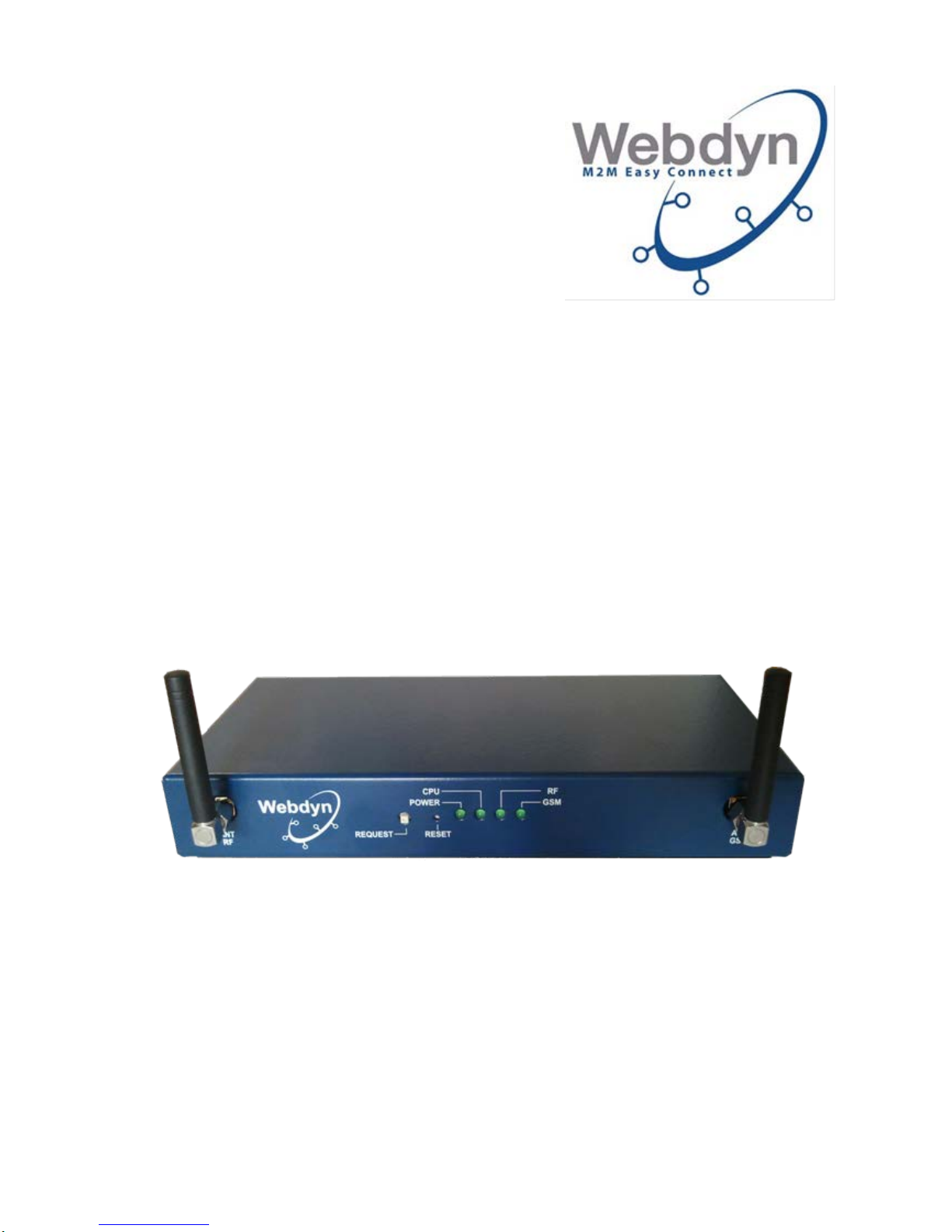
WebdynRF
Concentrator dedicated to smart metering and energy management
Installation Manual
Page 2

WEBDYN
WebdynRF
Installation Manual
WebdynRF – Installation Manual - Version 1.0 2
CONTENTS
CONTENTS ................................................................................................................ 2
1 Remarks concerning this manual ..................................................................... 4
1.1 Scope ......................................................................................................... 4
1.2 Product versions ........................................................................................ 4
1.3 Target group ............................................................................................... 5
1.4 General operating prin ci pl e ........................................................................ 5
2 Safety instructions ............................................................................................ 6
3 Unpacking ........................................................................................................ 7
3.1 Delivery contents ........................................................................................ 7
3.2 Identification of the gateway ....................................................................... 8
4 Mounting .......................................................................................................... 9
4.1 Choosing the environment ......................................................................... 9
4.2 Mounting the WebdynRF on its feet ......................................................... 10
4.3 Mounting the WebdynRF on a DIN Rail ................................................... 10
4.4 Wall mounting the WebdynRF .................................................................. 11
4.5 Mounting the remote GPRS/GSM antenna .............................................. 11
5 Electrical connection ...................................................................................... 12
5.1 Overview of the external interfaces and of the LEDs ............................... 13
5.2 Connecting the gateway to the Internet for communication with the remote
server ................................................................................................................ 14
5.2.1 Connection to the Internet via an ADSL line ...................................... 14
5.2.2 Internet connection via a GPRS or 3G link ........................................ 15
5.3 Connecting the gateway’s on-off output ................................................... 17
5.4 Connecting the gateway’s on-off inputs .................................................... 17
5.5 Connecting the gateway to Modbus equipment via the RS485 link .......... 17
5.6 Connecting the gateway to equipment via the RS232 link ....................... 19
6 Connecting to a local PC via Ethernet for configuration purposes ................. 19
6.1 Direct connection of the PC to the gateway. ............................................ 19
6.2 Connecting the PC to the gateway on a local network ............................. 20
6.3 Network configuration of the PC for accessing the gateway .................... 20
7 Connecting the power supply ......................................................................... 21
8 Commissioning the gateway .......................................................................... 22
8.1 Connection to the onboard Web interface ................................................ 22
8.2 Configuration of the gateway’s connectivity ............................................. 23
8.2.1 Configuration of the modem connection ............................................ 24
8.2.2 Configuration of the Et her net con nect ion ........................................... 25
8.2.3 Configuration of the remote FTP server ............................................. 25
8.2.4 Time zone configuration .................................................................... 26
8.2.5 Data transfer configuration ................................................................ 27
8.2.6 Request button .................................................................................. 28
8.3 System configuration ................................................................................ 28
Page 3

WEBDYN
WebdynRF
Installation Manual
WebdynRF – Installation Manual - Version 1.0 3
8.3.1 Configuration of Wavenis parameters ................................................ 28
8.3.2 Ports configuration ............................................................................. 29
8.4 Alarms configuration................................................................................. 30
8.4.1 System alarms ................................................................................... 30
8.4.2 Wavenis alarms ................................................................................. 31
8.4.3 On-off input alarms ............................................................................ 31
8.4.4 On-off output alarms .......................................................................... 32
8.5 Schedules configuration ........................................................................... 32
8.6 Configuration of the Wavenis radio network ............................................. 35
8.6.1 Configuration of the radio modules via the Web interface ................. 36
8.6.2 Configuration via the Wavenet Monitor and Toolbox software ........... 36
8.6.2.1 Installation of Com0Com .............................................................. 37
8.6.2.2 Installation of Visual C++ libraries ................................................ 40
8.6.2.3 Toolbox installation ...................................................................... 41
8.6.2.4 Using the gateway with Wavenet Monitor .................................... 42
8.6.2.5 Importing the Wavenis configuration into the gateway ................. 46
8.7 Metering configuration .............................................................................. 47
8.7.1 Pulse inputs ....................................................................................... 47
8.7.2 M-Bus ................................................................................................ 48
8.7.3 169 MHz Wireless Mbus .................................................................... 49
8.8 Modbus configuration ............................................................................... 50
8.9 Executable actions ................................................................................... 53
8.9.1 Request for connection to the remote server ..................................... 53
8.9.2 M-Bus scan request ........................................................................... 53
8.9.3 Reboot request .................................................................................. 53
8.9.4 Wavenis RSSI scan request .............................................................. 53
8.9.5 Uploading system files ....................................................................... 54
8.10 Request for connection to the remote server ........................................ 54
9 Check on the gateway’s smooth running ....................................................... 54
10 Local FTP server ........................................................................................ 55
11 Shutting down the WebdynRF gateway ..................................................... 55
12 Support ....................................................................................................... 55
Page 4
WEBDYN
WebdynRF
Installation Manual
WebdynRF – Installation Manual - Version 1.0 4
1 Remarks concerning this manual
This guide describes the assembly, installation and commissioning of the device.
Please ensure these instructions are always available.
For management instructions for the data exchanged by the gateway with the remote
server, refer to the operating manual for the WebdynRF gateway (cf. MEWebdynRF_FR.pdf).
1.1 Scope
This technical description is valid for Wavenis WebdynRF gateways from hardware
version 1 and software version 2.4.0. onwards.
1.2 Product versions
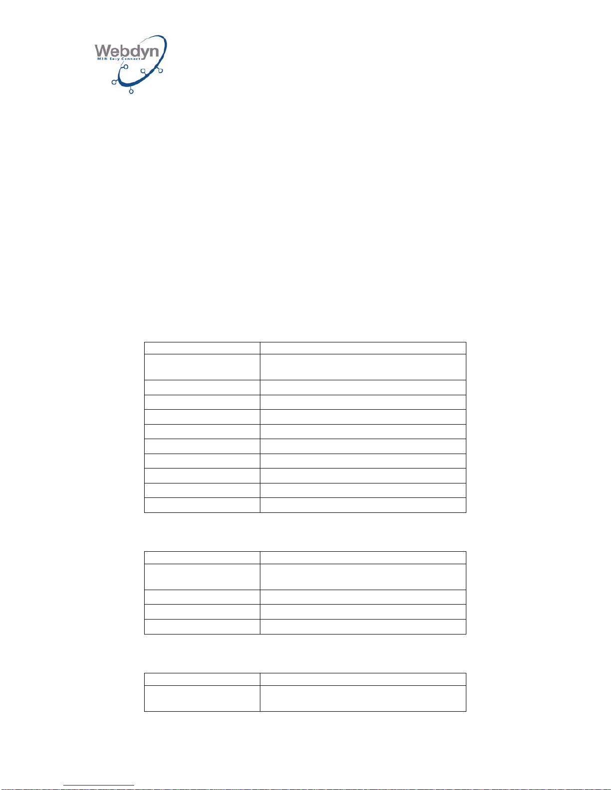
Depending on the type of GSM modem and radio card, there are several product
versions:
Wavenis radio card:
Product references
Versions
WG0606-A01
2G modem – 868 MHz/25 mW Wavenis
WG0606-A02
3G modem – 868 MHz/25 mW Wavenis
WG0606-A03
2G modem – 868 MHz/500 mW Wavenis
WG0606-A04
3G modem – 868 MHz/500 mW Wavenis
WG0606-A11
2G modem – 915 MHz/25 mW Wavenis
WG0606-A12
3G modem – 915 MHz/25 mW Wavenis
WG0606-A13
2G modem – 915 MHz/500 mW Wavenis
WG0606-A14
3G modem – 915 MHz/500 mW Wavenis
WG0606-A21
2G modem – 433 MHz/10 mW Wavenis
WG0606-A22
3G modem – 433 MHz/10 mW Wavenis
Wireless M-Bus radio card:
Product references
Versions
WG0607-A01
WebdynRF-WirelessMbus-868 MHz-2G
WG0607-A02
WebdynRF-WirelessMbus-868 MHz-3G
WG0607-A11
WebdynRF-WirelessMbus-169 MHz-2G
WG0607-A12
WebdynRF-WirelessMbus-169 MHz-3G
RFID radio card:
Product reference
Versions
WG0608-A01
2G modem - RFID
Page 5
WEBDYN
WebdynRF
Installation Manual
WebdynRF – Installation Manual - Version 1.0 5
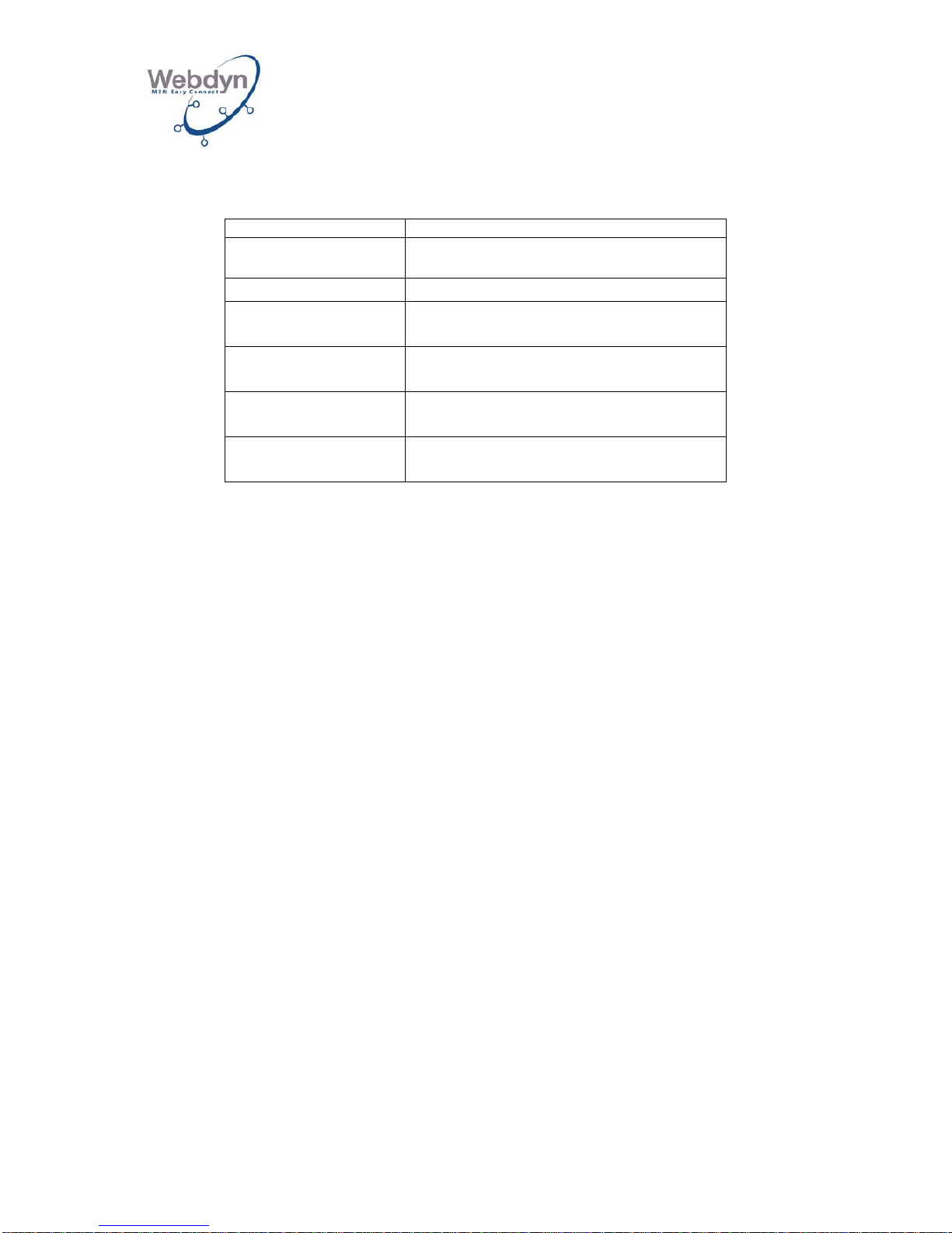
Accessories common to all products:
Product references
Versions
AC0102-02
12V external power supply unit
AC0103-00
24V DIN rail-mounted power supply
AC0201-01
Remote dual-band GPRS antenna with 5m
of cable
AC0201-02
Remote dual-band GPRS antenna with
20m of cable
AC0201-03
Remote dual-band GPRS antenna with
10m of cable
AC0501-01
IP67 box, circuit breaker, 24V DC power
supply, UPS unit and 12V lead batteries
This manual covers all versions of the product.
1.3 Target group
This guide is aimed at installers.
1.4 General operating principle
The WebdynRF platform is the new range of Webdyn concentrators dedicated to
wireless networks. Gathering data from meters or sensors and checking I/Os are
basic functionalities for the WebdynRF gateway. The services targeted by the
WebdynRF gateway are remote meter reading, and buildings energy management.
Page 6
WEBDYN
WebdynRF
Installation Manual
WebdynRF – Installation Manual - Version 1.0 6
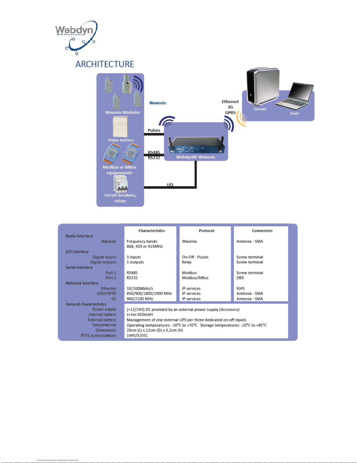
Technical Specifications: Wavenis WebdynRF
2 Safety instructions
You absolutely must follow all the safety instructions featured in this guide.
Failure to follow these instructions may damage the devices and endanger people.
Page 7
WEBDYN
WebdynRF
Installation Manual
WebdynRF – Installation Manual - Version 1.0 7
The WebdynRF gateway contains a Lithium battery:
ATTENTION
THERE IS A RISK OF AN EXPLOSION OCCURRING IF THE BATTERY IS
REPLACED WITH THE WRONG TYPE OF BATTERY .
DISPOSE OF USED BATTERIES IN ACCORDANCE WITH INSTRUCTIONS
3 Unpacking
3.1 Delivery contents
Check that all the items have been delivered and that the device has not been
damaged. Contact Webdyn if the delivery is incomplete or damaged.
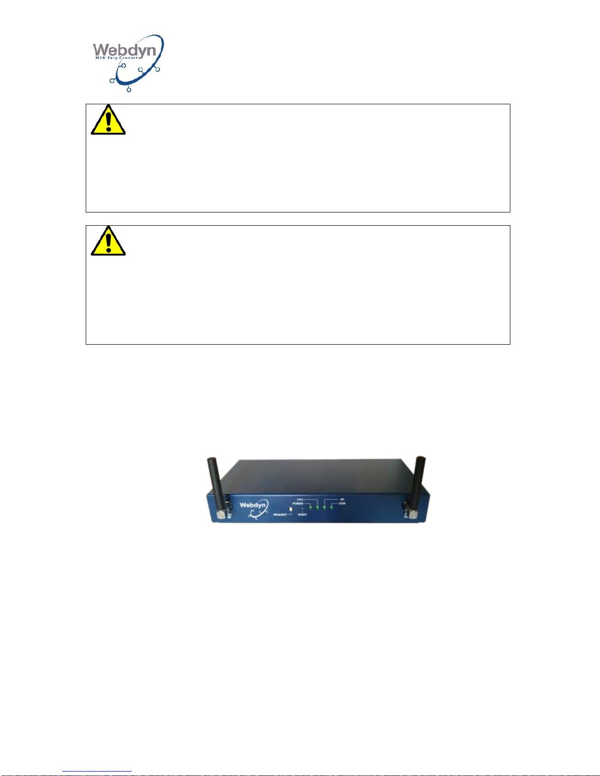
WebdynRF Gateway
(Ref.: WG0606-AXX)
The following are delivered with the gateway:
• 2 L-shaped antennas (RF/Modem)
• 1 set of Weidmüller connectors
The WebdynRF gateway may be damaged by ESDs (Electrostatic Discharges).
•
All of the installation work for the WebdynRF should only be carried out by an
authorized professional electrician.
•
Avoid any contact with the components’ connections or the connectors’
contacts.
Page 8
WEBDYN
WebdynRF
Installation Manual
WebdynRF – Installation Manual - Version 1.0 8
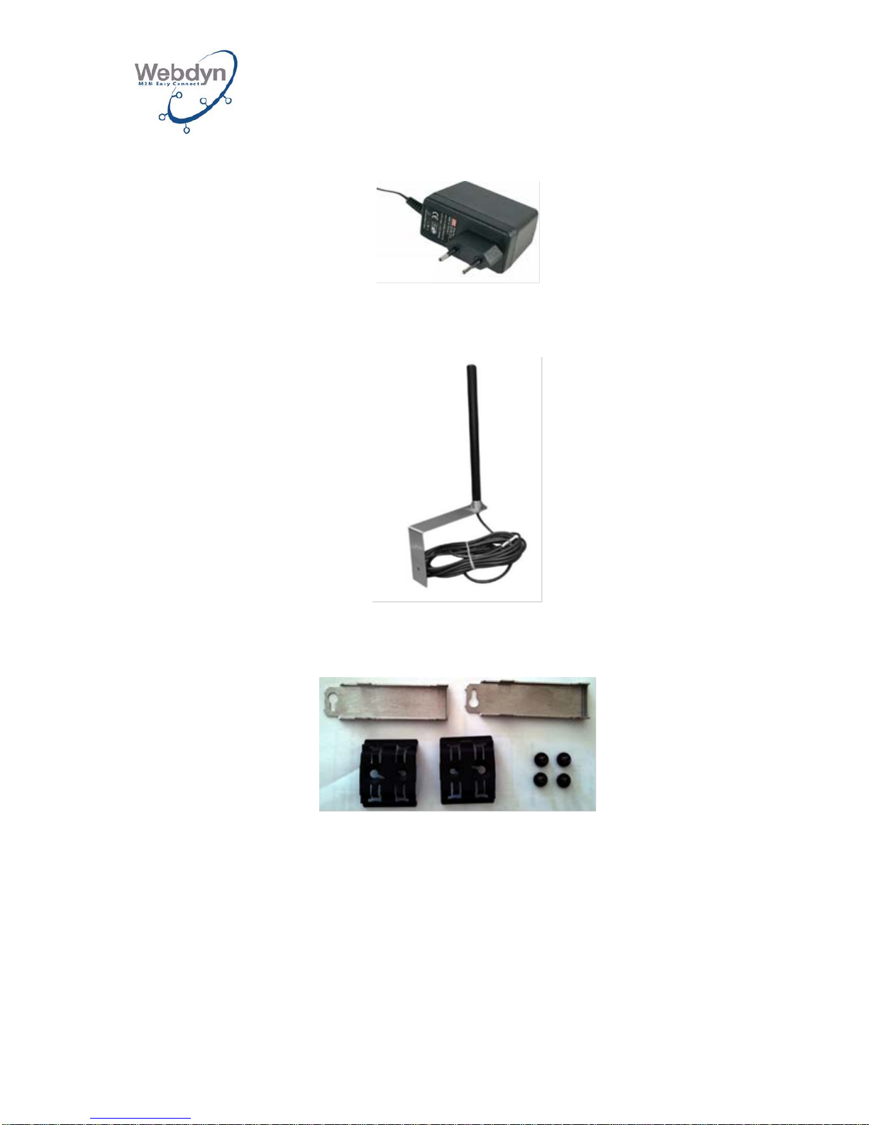
Only in the event of being ordered as an accessory:
12V external power supply unit
(Ref.: AC0102-02)
Remote dual-band GPRS antenna with 5m or 20m of cable
(Ref.: AC0201-01 or AC0201-02)
DIN Rail and wall-mounting fastening kit
(Ref.: AC0301-01)
3.2 Identification of the gateway
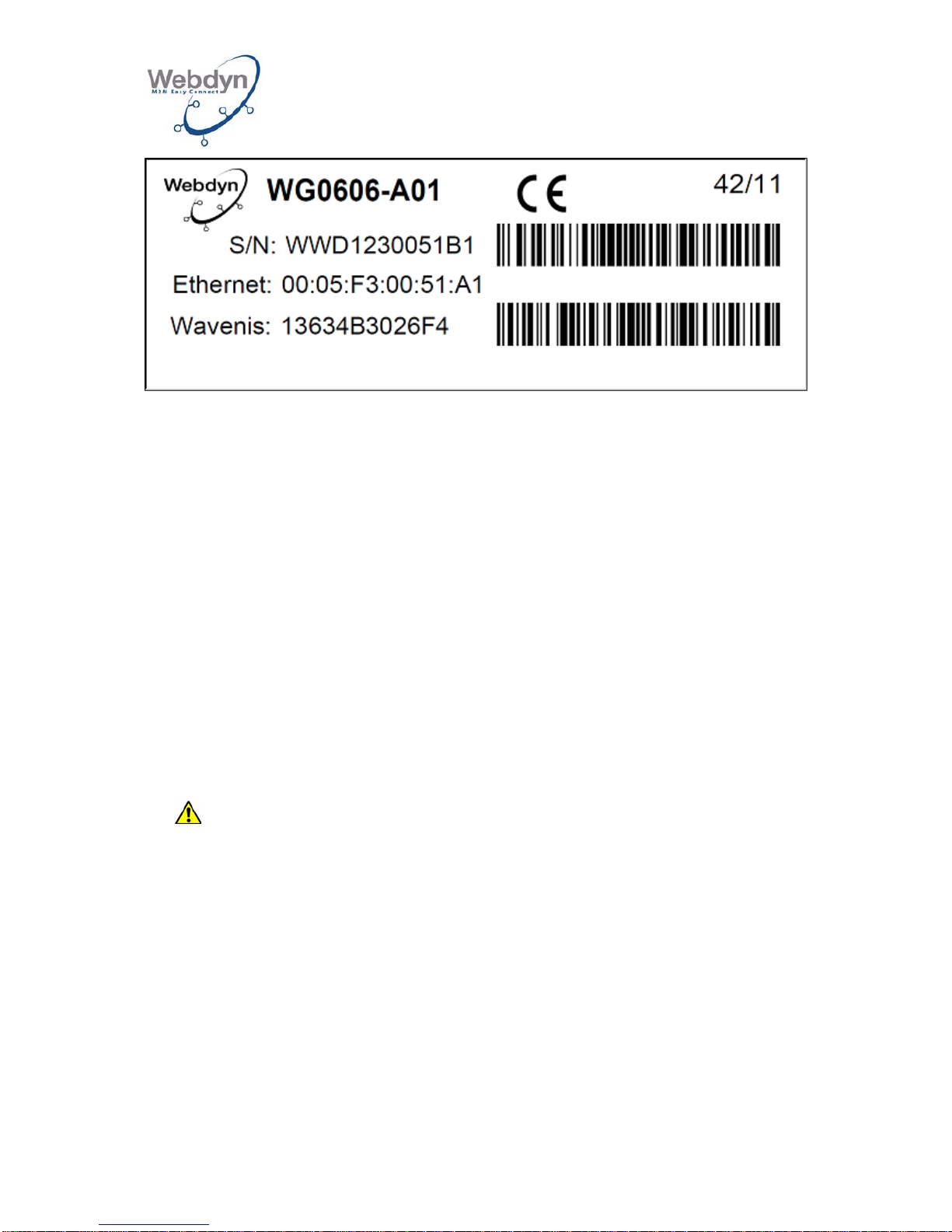
Information label:
You can identify the WebdynRF gateway from its information label, which is located
beneath the box.
Page 9
WEBDYN
WebdynRF
Installation Manual
WebdynRF – Installation Manual - Version 1.0 9
This label contains (in the case of the Wavenis version):
- The name of the product (WG0606-A01).
- The production date (in WW/YY format in the top right-hand corner).
- The serial No. in clear text and as a code 128 barcode.
- The MAC address (Ethernet) in clear text.
- The Wavenis radio address in clear text and as a code 128 barcode.
Software version:
You will find the software version on the gateway’s Web interface. The software
version is indicated on the Overview page.
4 Mounting
4.1 Choosing the environment
Comply with the following environmental conditions.
• Operating temperature: -5°C to +45°C.
Battery performance declines in temperatures lower than 0°C and higher
than 45°C.
• Storage temperature: -20°C to +45°C (for a period of less than one month)
-20°C to +35°C (for a period longer than one month)
• The ambient humidity must be between 10 and 90% RH.
• Protect the WebdynRF from dust, humidity, harmful substances, and
condensation.
• The distance between the WebdynRF and the Modbus equipment must not
exceed the maximum permitted distance for the corresponding type of interface
(RS485 or RS232).
• If using the cellular link, make sure that reception is optimal whilst mounting the
unit (see 5.2.2).
Page 10
WEBDYN
WebdynRF
Installation Manual
WebdynRF – Installation Manual - Version 1.0 10
The WebdynRF gateway must send data from your installation to the remote server
automatically and at regular intervals: for this, you will need to fulfill the following
conditions:
• To send installation data via Ethernet, the network must include a router enabling
access to the Internet.
• To send installation data via a GSM link, the network coverage must be
satisfactory.
• If you are using the remote GSM antenna option, refer to Chapter 4.5 before
assembling the gateway.
To optimize Wavenis and GSM reception sensitivity, you absolutely must keep a
clear space of 20 cm around the antennas.
4.2 Mounting the WebdynRF on its feet
The WebdynRF may be placed on its feet on a flat surface.
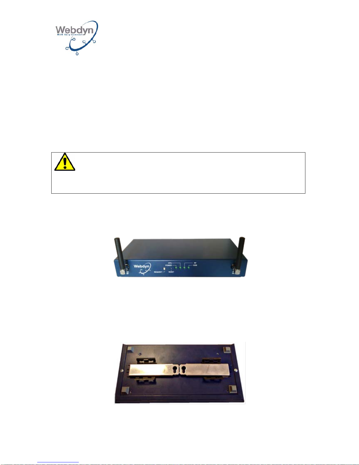
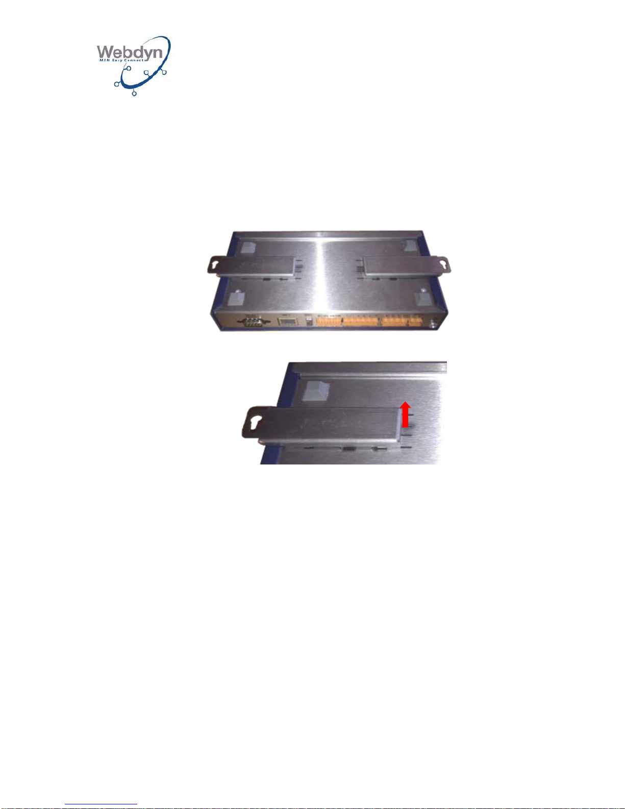
4.3 Mounting the WebdynRF on a DIN Rail
The WebdynRF may be mounted on a 35mm standardized metal rail (DIN Rail).
This rail mounting requires additional mounting accessory Ref: KFIX01.
1. Mount the fastening kit onto the gateway:
Page 11
WEBDYN
WebdynRF
Installation Manual
WebdynRF – Installation Manual - Version 1.0 11
2. Hook the WebdynRF onto the rail using the two supports.
4.4 Wall mounting the WebdynRF
The WebdynRF may be fastened onto a wall.
This rail mounting requires additional mounting accessory Ref: KFIX01.
1. Mount the fastening kit onto the gateway:
2. Lift the 2 tabs in order to lock the fastenings into position:
3. Determine the gateway’s position and mark the drill holes using a
pencil.
4. Drill the holes (diameter: 6 mm) in the locations marked and insert the
pins.
5. Use screws to fasten the WebdynRF to the wall.
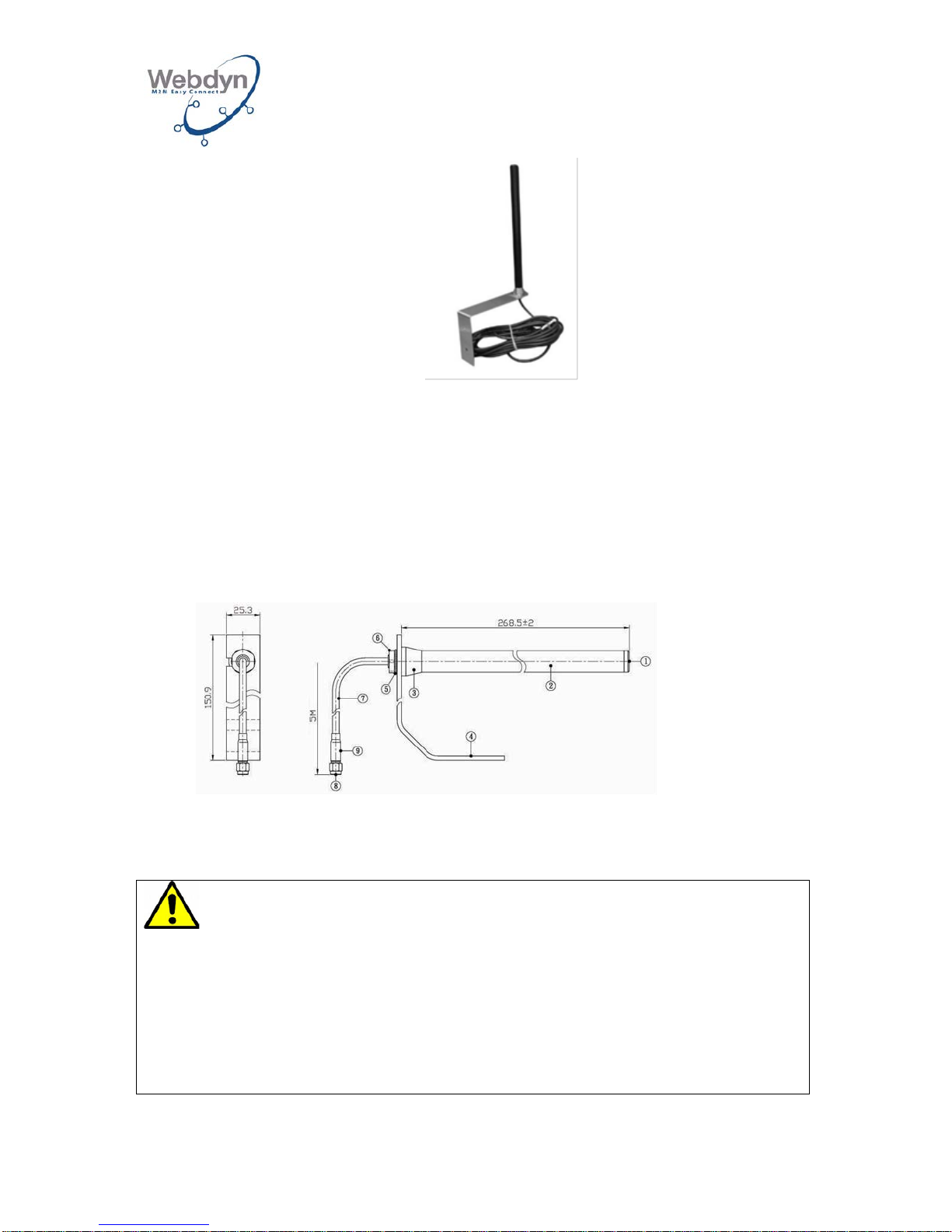
4.5 Mounting the remote GPRS/GSM antenna
Only in the event of ordering the following accessory: Remote dual-band GPRS
antenna with 5 m or 20 m of cable (Ref.: AC0201-01 or AC0201-02).
Page 12
WEBDYN
WebdynRF
Installation Manual
WebdynRF – Installation Manual - Version 1.0 12
Contents of the kit:
A: 1 antenna.
B: 1 antenna bracket with a 5 or 20 meter antenna cable.
1. Determine the position of the antenna by using the bracket on the wall, and
mark drill holes using a pencil.
2. Drill the holes (diameter: 6 mm) in the locations marked and insert the pins.
3. Use screws to fasten the antenna bracket to the wall.
4. Screw the antenna onto the antenna cable.
5. Screw the cable onto the WebdynRF antenna socket.
Cable: RG-58.
Frequencies: 824-9 60 M Hz ; 1710-1990 MHz.
5 Electrical connection
•
All the cabling work absolutely must be carried out by a specialized qualified
electrician.
• Before installation, all the devices connected
to the corresponding
communication bus must be disconnected from the electrical network (DC
and AC).
•
Please follow all the safety instructions featured in your equipment’s
documentation.
Page 13
WEBDYN
WebdynRF
Installation Manual
WebdynRF – Installation Manual - Version 1.0 13
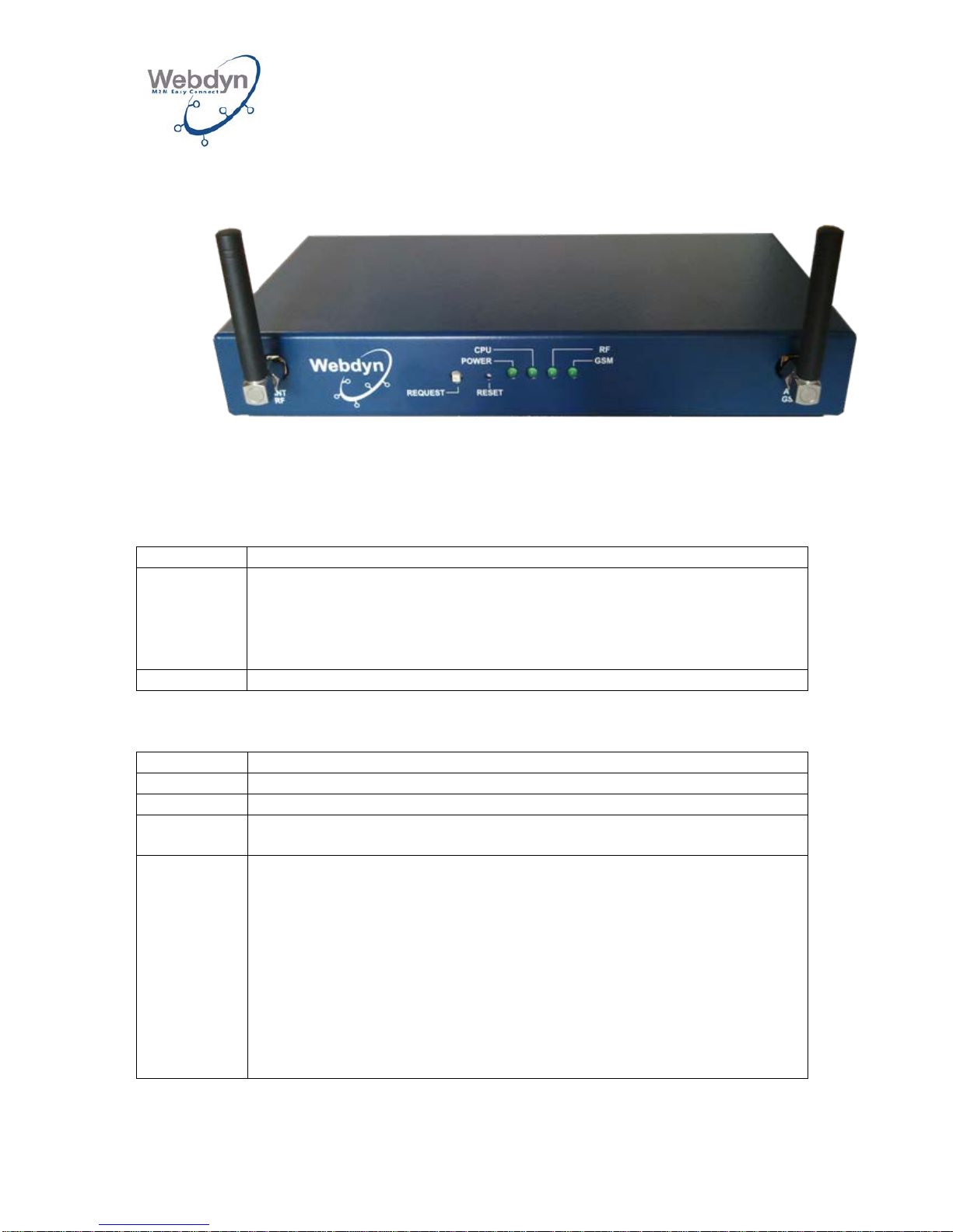
5.1 Overview of the external interfaces and of the LEDs
The box’s front panel:
Antennas:
RF ANT: Antenna for the RF link.
GSM ANT: Antenna for the GPRS or 3G link.
The buttons:
Button
Description
REQUEST
Short press => Connection request
Long press (3s) => Displays the reception level for the G
SM signal
(see GSM LED)
3 successive long presses => Returns parameters to their factory
settings
RESET
Restarts the gateway’s hardware
The LEDs:
LED
Description
POWER
Lights up when the product is powered up.
CPU
Lights up depending on CPU activity.
RF
As its default setting, it is off. It flashes in the event of RF traffic, or
when a computer is connected in transparent mode.
GSM
Lights up during GSM connecti on.
Lights up for 1 second upon receiving an SMS.
When the Request button is pressed for
a long time, it indicates the
level of the RSSI signal received by a number of flashes (0 to 5
times).
0 – Signal power ≤ -112 dBm
1 – Signal power of -111 dBm to -96 dBm
2 – Signal power of -96 dBm to -81 dBm
3 – Signal power of -81 dBm to -66 dBm
4 – Signal power of -66 dBm to -51 dBm
5 – Signal power > -51 dBm
Page 14
WEBDYN
WebdynRF
Installation Manual
WebdynRF – Installation Manual - Version 1.0 14
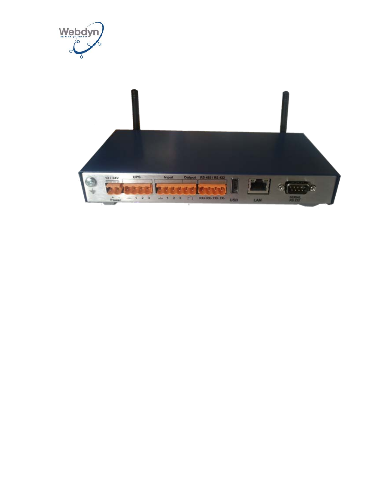
The box’s rear panel:
12/24V: The gateway’s power supply.
UPS: Uninterruptible power supply status inputs.
Input: 3 on-off inputs.
Output: 1 on-off output.
RS485/RS422: 1 RS485/RS422 port.
USB: USB socket.
LAN: LAN socket.
Serial RS232: RS232 port, type DB9.
5.2 Connecting the gateway to the Internet for communication
with the remote server
This chapter describes connecting the WebdynRF to the Internet for communication
with the remote server. This communication may be selected from one of three
different types of media:
• Ethernet via an ADSL line.
• GPRS (product versions WG0606-A01 and WG0606-A03).
• 3G (product versions WG0606-A02 and WG0606-A04).
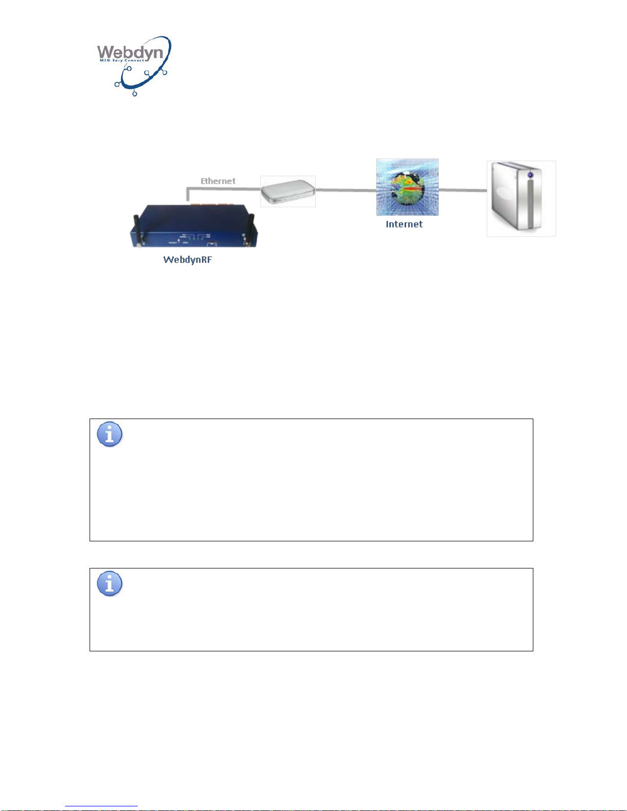
5.2.1 Connection to the Internet via an ADSL line
Connect the WebdynRF gateway to the ADSL network by using the Ethernet socket
marked LAN on the gateway’s rear panel.
Page 15
WEBDYN
WebdynRF
Installation Manual
WebdynRF – Installation Manual - Version 1.0 15
The length and quality of the cable may have negative repercussions on the quality
of the signal.
Use an Ethernet cable complying with the following remarks:
• A straight cable is recommended.
• Use a good-quality cable: as a minimum, a category 5 (STP Cat 5) or higher
shielded twisted pair cable.
• The maximum permitted length of the Ethernet cable is 100 m per segment.
Upon delivery, the IP configuration parame ters for the Webd ynRF gateway are
as follows:
IP address: 192.168.1.12
Sub-network mask: 255. 255. 255.0
DHCP: Deactivated
Network administrator
If your local network is managed by a network administrator, contact him before
integrating the WebdynRF gateway into your network.
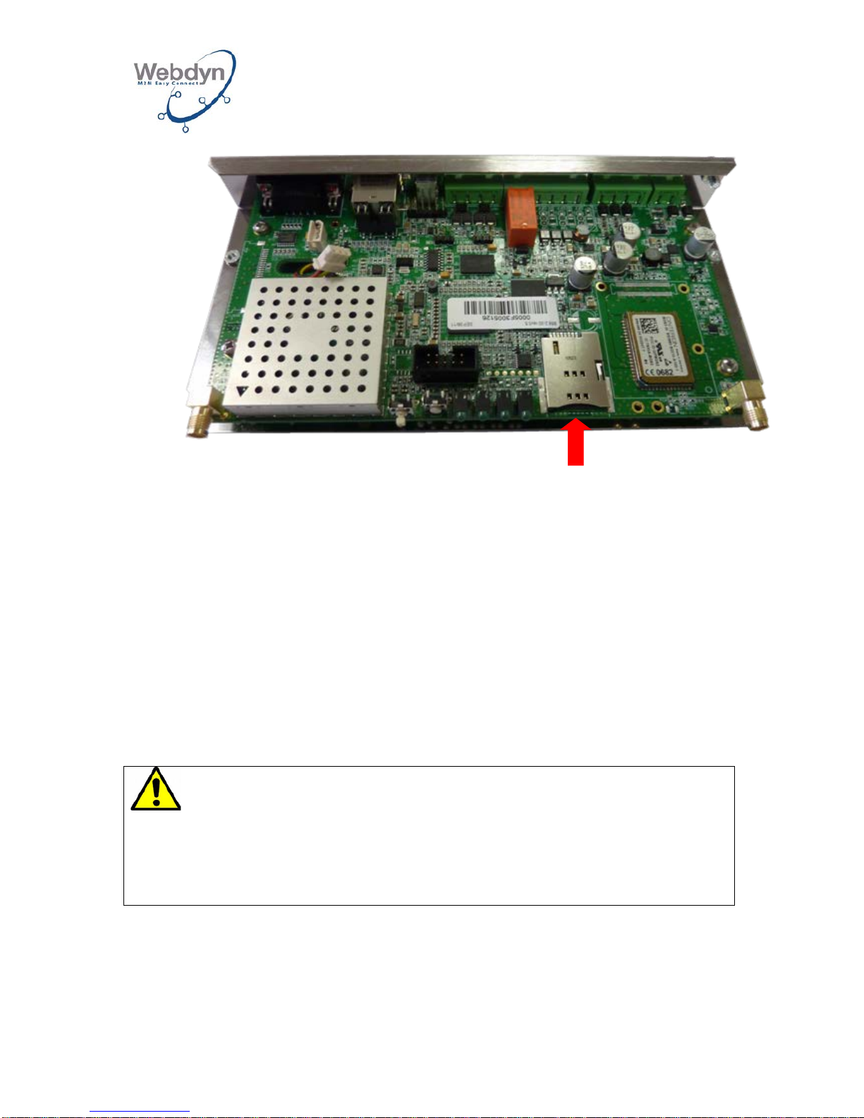
5.2.2 Internet connection via a GPRS or 3G link
To use a GPRS link or a 3G link and to enable the gateway to communicate with the
remote server, you need to insert a SIM card into the gateway’s internal drawer.
Modem/Router
FTP server
Page 16
WEBDYN
WebdynRF
Installation Manual
WebdynRF – Installation Manual - Version 1.0 16
To ensure smooth running of the WebdynRF in GPRS or 3G mode, you must insert a
SIM card with the following characteristics:
- Possibility of receiving and sending SMSs.
- GPRS or 3G communication included.
Insert the SIM card into the product.
In the gateway’s factory configuration, the code mana gement setting is PIN Mode =
off (see 8.2.1).
There are three possible scenarios:
- The PIN code is deactivated: modem communication is active.
- The PIN code is activated and equals 0000: modem communication is active.
- The PIN code is activated and differs from 0000: modem communication is
experiencing an error.
To communicate with the remote server via GSM, the gateway must be positioned in
an optimal GSM coverage area.
To ascertain the signal quality received by the gateway, use the Request button,
giving it a long press (for 3 seconds).
If the SIM card has a PIN code that has been activated but is different from 0000
when the gateway is first started up, it will be blocked after 3 attempts.
You ca
n unblock it by using a mobile phone with the PUK code provided by your
operator.
Page 17
WEBDYN
WebdynRF
Installation Manual
WebdynRF – Installation Manual - Version 1.0 17
The GSM (RSSI) signal reception level is displayed on the GSM LED by a number of
flashes (0 to 5 times).
The correspondence between the number of flashes and the power of the signal is
shown below:
0 – Signal power ≤ -112 dBm
1 – Signal power of -111 dBm to -96 dBm
2 – Signal power of -96 dBm to -81 dBm
3 – Signal power of -81 dBm to -66 dBm
4 – Signal power of -66 dBm to -51 dBm
5 - Signal power > -51 dBm
As a minimum, the power of the signal received must equal -
96 dBm or 2
flashes.
5.3 Connecting the gateway’s on-off output
The WebdynRF gateway has 1 on-off output.
This output may be used as a digital output.
5.4 Connecting the gateway’s on-off inputs
The WebdynRF gateway has 3 on-off inputs.
These inputs may be used as digital inputs for triggering alarms or as a pulse meter
(see the operating manual for furt her detai l s) .
To avoid damaging the gateway, do not input current or voltage via the on-off
inputs.
In pulse meter mode, the pulse length must be 10 ms as a minimum and 1000 ms as
a maximum in order to be taken into account.
5.5 Connecting the gateway to Modbus equipment via the RS485
link
This chapter describes connecting the WebdynRF to the RS485 bus for
communication with Modbus equipment.
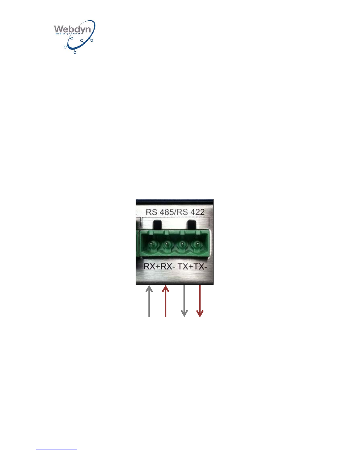
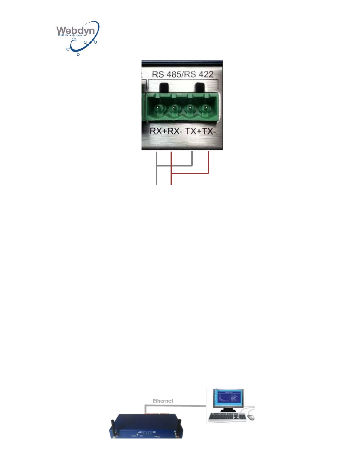
The RS485 interface used is marked with the label RS485/RS 422.
This is a 4-wire or 2-wire interface.
Choosing between 4 wires or 2 wires is done automatically by the onboard software.
Page 18
WEBDYN
WebdynRF
Installation Manual
WebdynRF – Installation Manual - Version 1.0 18
The gateway may be located at the end of the RS485 communication bus, or in the
middle of the bus.
To ensure that the RS485 data bus functions, it must have a 120 Ohm plug on both
ends.
Depending on the positioning of the gateway on the bus, this plug must be placed
outside the box.
Consult the Modbus equipment documentation concerning its RS485 cabling and
connection principle.
Once the RS485 cable is available in the vicinity of the gateway:
1. Strip off approximately 4 cm of the RS485 communication cable’s sheath.
3. Cut the shielding back to the length of the cable sheath.
4. Strip the wires to a length of approximately 6 mm.
5. Connect the conductors to the connector marked RS485/RS422, following the
assignments in your RS485 communication bus.
4-wire RS485 assembly:
2-wire RS485 assembly:
TX+
TX-
RX+
RX-
Page 19
WEBDYN
WebdynRF
Installation Manual
WebdynRF – Installation Manual - Version 1.0 19
5.6 Connecting the gateway to equipment via the RS232 link
The RS232 port may be used to gather data from M-Bus equipment. An M-Bus
transceiver must be connected to the RS232 port and this port must be configured in
M-Bus mode (see section 8.3.2).
M-Bus equipment must be configured with a unique address on the bus.
A scan of the bus must be initiated from the Web interface (see section 8.9.2). The MBus equipment discovered during this scan will be queried upon each occurrence of
the associated scheduler. If some equipment items are either removed from the bus
or added to it, a new scan must be initiated so that the gateway will factor in the
modification.
6 Connecting to a local PC via Ether net f or conf iguration
purposes
During the initial commissioning, the WebdynRF gateway must be configured via the
Ethernet network using a PC (either a portable or fixed PC).
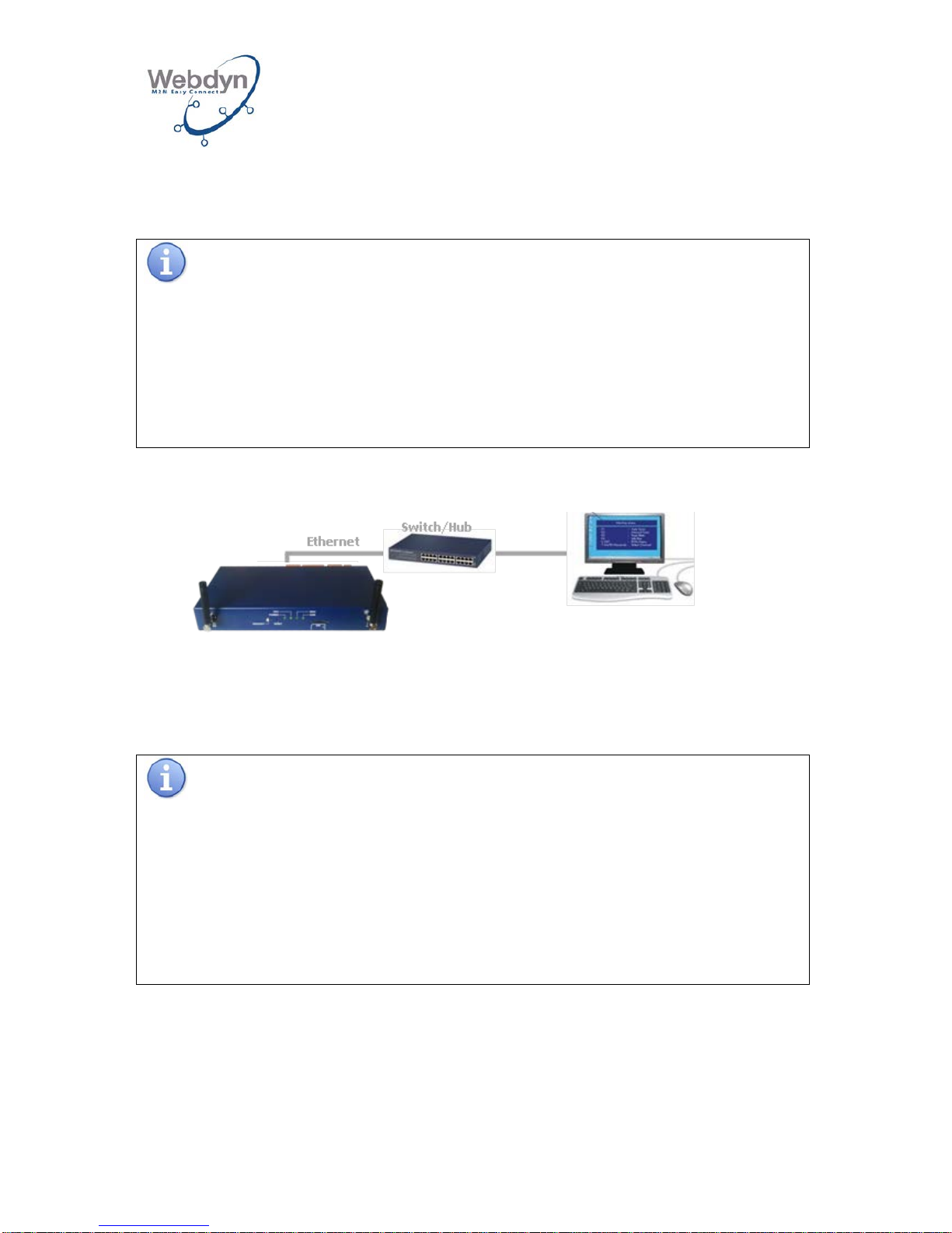
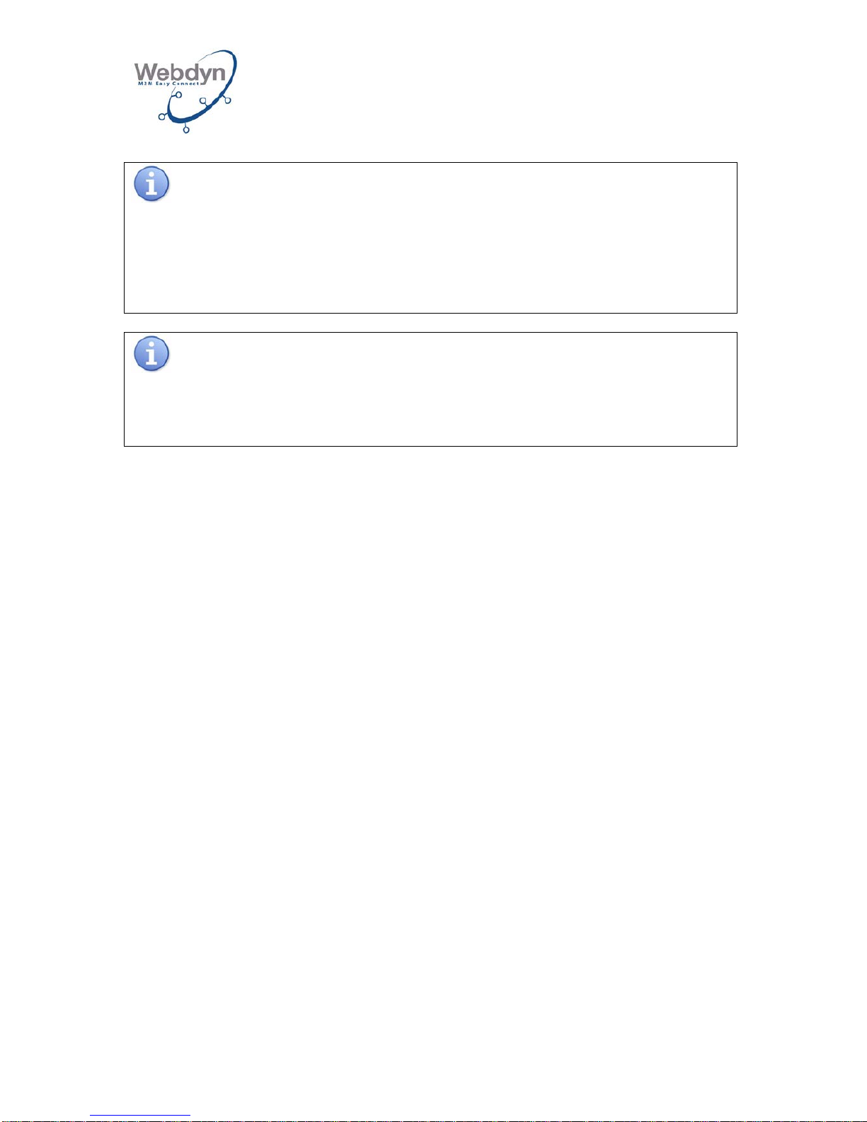
The PC may be connected to the gateway directly, or integrated into the gateway’s
local network, particularly if the ADSL link is used for communication with the remote
server.
This chapter describes the two types of connection for hooking up a PC to the
gateway.
6.1 Direct connection of the PC to the gateway.
D+
D-
Page 20
WEBDYN
WebdynRF
Installation Manual
WebdynRF – Installation Manual - Version 1.0 20
Connect the WebdynRF gateway directly to the PC by using the Ethernet interface on
the box and a straight or crossover Ethernet cable. To identify the PC’s Ethernet
socket, refer to the PC’s documentation.
Recommendations relating to the Ethernet cabling:
The length and quality of the cable may have negative repercussions on the quality
of the signal:
•
Use a good quality cable; as a minimum a category 5 (STP Cat 5) or higher
shielded twisted pair cable.
• The maximum permitted length of the Ethernet cable is 100 m per segment.
6.2 Connecting the PC to the gateway on a local network
Connect the WebdynRF gateway to the local network by using the box’s Ethernet
interface and a straight or crossover Ethernet cable. To identify the Switch/Hub’s
Ethernet socket, refer to its documentation.
Recommendations concerning Ethernet cabling:
The length and quality of the cable may have negative repercussions on the quality
of the signal:
• A straight cable is necessary.
•
Use a good quality cable; as a minimum a category 5 (STP Cat 5) or higher
shielded twisted pair cable.
• The maximum permitted length of the Ethernet cable is 100 m per segment.
6.3 Network configuration of the PC for accessing the gateway
With the PC connected directly to the gateway (see 6.1) or connected to the gateway
on a local network (see 6.2), you need to configure a fixed IP address on the PC
within the same IP address field and within the same sub-network as for the
WebdynRF gateway.
Page 21
WEBDYN
WebdynRF
Installation Manual
WebdynRF – Installation Manual - Version 1.0 21
Upon delivery, the settings of the WebdynRF gateway are as follows:
IP address: 192.168.1.12
Sub-network mask: 255. 255. 255.0
DHCP: deactivated
Network administrator
If your local ne
twork is managed by a network administrator, contact him before
integrating the WebdynRF gateway into your network.
The next step enables the network address for a PC to be configured in order to gain
access to the WebdynRF gateway:
Configuration of a second IP address on the PC:
1. In a Windows environment (2000 or XP) click on Start/Parameters/Network
connections and remote access. The Network connections and remote access
window will be displayed.
2. Using the right button, click on Local network and the n click on Properties.
3. Select Internet Protocol (TCP/IPv4) and then click on Properties.
4. Then, click on Advanced.
5. In the IP address fiel d, c l ic k on Add.
6. Enter the IP address 192.168.1.xxx (xxx from 1 to 254 and different from 12) and
the sub-network mask 255. 255. 255.0.
7. Click on Add.
8. To validate the settings, click on OK in each of the three windows.
9. Close the Network connection and remote access window.
7 Connecting the power suppl y
Connect the power supply only when all the other devices are connected to the
WebdynRF gateway.
Check whether the following connections (if used) are connected correctly before
powering up the gateway:
• On-off output.
• On-off inputs.
• RS485 input used for connecting equipment items.
• RS232 output used for connecting equipment items.
Page 22
WEBDYN
WebdynRF
Installation Manual
WebdynRF – Installation Manual - Version 1.0 22
1- Connect the cable to the 12/24V input of the gateway’s thumbscrew connector,
making sure the polarity is correct.
2- Connect the power supply used to the mains.
Start-up phase for the WebdynRF gateway:
Before connecting the power supply unit, LED POWER
will light up. The gateway will
take approximately 20 seconds to start up. Its initialization is completed when the
CPU LED flashes on and off over a period of 0.5 s.
Information about the characteristics of the power supply to be used:
The power supply must deliver 12 to 24V and 15W.
8 Commissioning the gateway
The WebdynRF gateway is configured via the integrated Web interface.
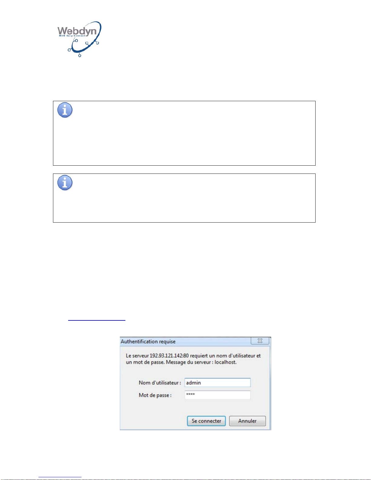
8.1 Connection to the onboard Web interface
1. Launch the Web browser
The Web interface is compatible with the latest versions of Firefox, Chrome and
Internet Explorer. Older versions may work but are no longer supported (for
example IE 7).
2. Visit the WebdynRF gateway homepage using the browser’s address line
http://192.168.1.12.
3. A login window will be displayed:
The default password for the administrator is high.
Page 23
WEBDYN
WebdynRF
Installation Manual
WebdynRF – Installation Manual - Version 1.0 23
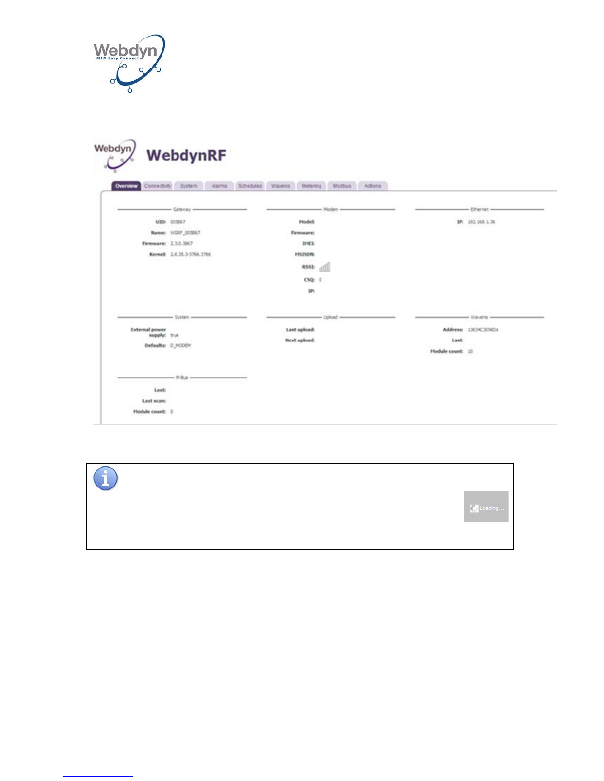
4. The homepage will be displayed:
If Web pages are accessed during the gateway’s initialization phase, the
logo will be displayed.
Wait until the gateway is fully initialized before accessing Web pages.
8.2 Configuration of the gateway’s connectivity
The Connectivity page enables the gateway to be configured so that it may
communicate with the remote server.
Page 24
WEBDYN
WebdynRF
Installation Manual
WebdynRF – Installation Manual - Version 1.0 24
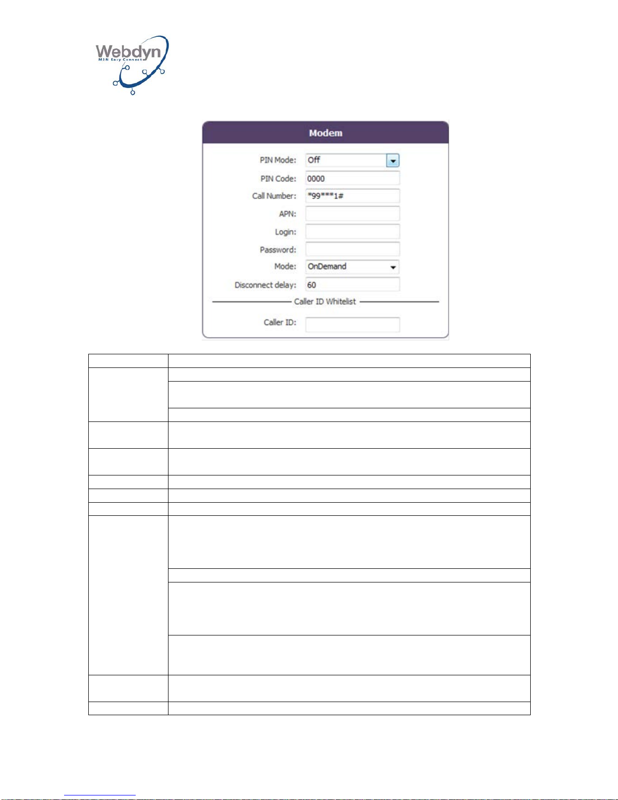
8.2.1 Configuration of the modem connection
Parameters
Description
PIN Mode
Off: The SIM card’s PIN code must be deactivated.
Manual: The SIM card’s PIN code must be entered in the PIN Code
box.
Automatic: Not implemented.
PIN Code
The SIM card’s PIN code to be filled in if Manual is selected in PIN
Mode.
Call Number
GPRS call number. The default number *99***1# is valid in the
majority of cases.
APN
Name of the APN of your mobile operator.
Login
Your mobile operator’s APN user name.
Password
Your mobile operator’s APN password.
Mode
OnDemand: The gateway establishes the connection only when it has
to communicate with the remote server. It cuts it off when the data
transfer is completed after a timeframe that can be configured in
Disconnect delay.
AlwaysOn: Not implemented.
AlwaysOff: This mode is to be used in the case of connection with the
remote server via Ethernet. This connection is done via modem, but if
a valid SIM card is inserted, the gateway may receive incoming SMSs
or calls and transmit SMSs.
Off: The modem is always off. This mode is to be used in the case of
connection with the remote server via Ethernet without the possibility
of receiving calls or SMSs or sending SMSs.
Disconnect
delay
Value of the wait delay in OnDemand between the end of data
exchanges and the end of the connection.
Caller ID
List of the telephone numbers permitted for incoming SMSs and calls.
Page 25
WEBDYN
WebdynRF
Installation Manual
WebdynRF – Installation Manual - Version 1.0 25
Consult your mobile operator in order to obtain the information (APN, login,
password) relating to your SIM card.
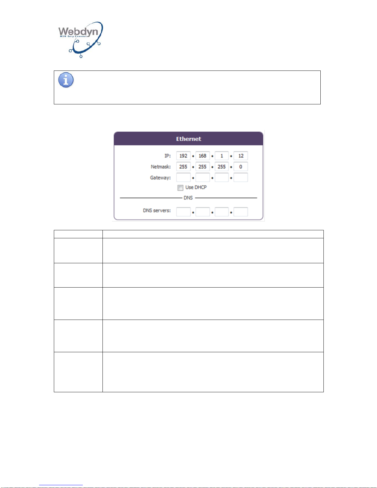
8.2.2 Configuration of the Ethernet connection
Parameters
Description
IP
Enter the IP address at which the WebdynRF gateway is accessible.
Netmask
Enter the sub-network mask for your network. This mask limits the
Ethernet network to the IP addresses defined and separates the
network ranges from each other.
Gateway
Enter the address of the gateway for your network. The gateway’s
address is the IP address of the device that establishes the Internet
connection. Generally speaking, the address entered here is the one
for your ADSL router.
Use DHCP
You have the option of obtaining the Ethernet parameters
automatically if the network infrastructure enables it. In this case,
select the dynamic mode and refer to the configuration of your DHCP
server in order to find out your gateway’s IP address.
DNS servers
The DNS (Domain Name System) server translates the explicit Web
addresses (for example www.webdyn.com) into the corresponding IP
addresses. Here, enter the addresses of the DNS servers that you
have received from your ISP (Internet Service Provider). You can also
enter your router’s IP address.
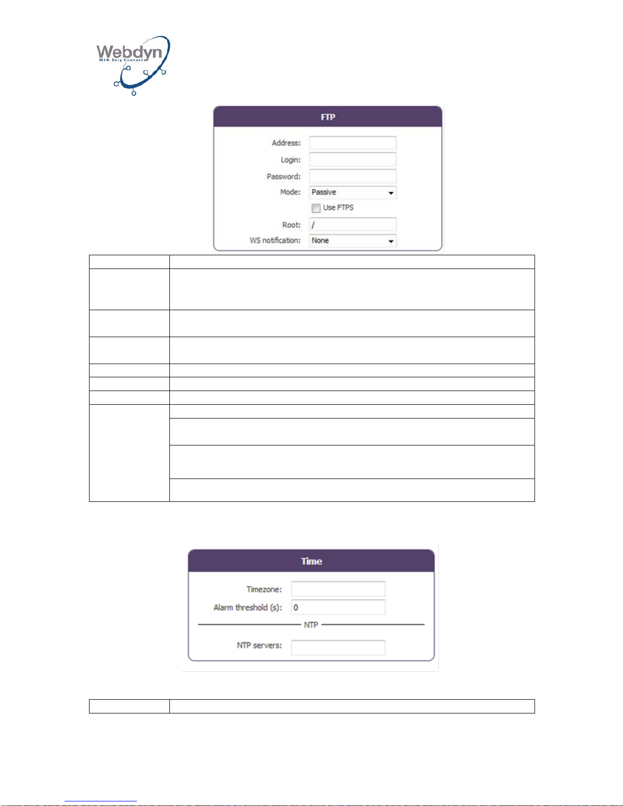
8.2.3 Configuration of the remote FTP server
This field makes it possible to fill in the configuration of the remote FTP server
enabling data exchanges.
Page 26
WEBDYN
WebdynRF
Installation Manual
WebdynRF – Installation Manual - Version 1.0 26
Parameters
Description
Address
IP address or name of the remote FTP server
Login
The user name used by the gateway for connection to the remote
FTP server
Password
The password used by the gateway for the connection to the remote
FTP server
Mode
Active or passive
Use FTPS
To be ticked if the remote server is an FTPS one
Root
The root directory on the remote FTP server
WS
notification
None: No Web Services notification
Put: Notification via Web Services when the gateway puts data on the
FTP server
Get: Notification via Web Services when the gateway downloads data
from the FTP server
Both: Put & Get
8.2.4 Time zone configuration
Parameters
Description
Page 27
WEBDYN
WebdynRF
Installation Manual
WebdynRF – Installation Manual - Version 1.0 27
Timezone
Text field for indicating the time zone. The format must comply with
the TZ format; see the link:
http://en.wikipedia.org/wiki/Zone.tab
Alarm
threshold (s)
Difference in seconds between the gateway time and the NTP
synchronization time, above and beyond which an alarm is emitted
NTP servers
IP addresses of the NTP servers used for synchronization of the
gateway’s clock
8.2.5 Data transfer configuration
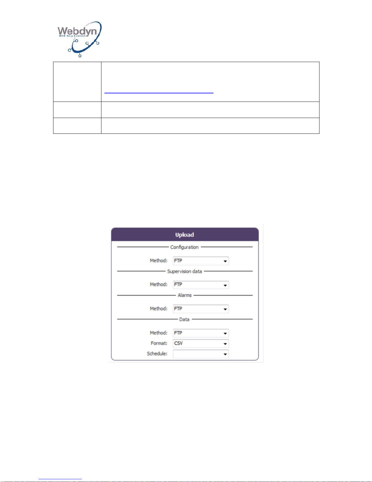
The gateway can put 4 types of data on the remote server:
• The gateway’s configuration data.
• The gateway’s supervision data.
• Alarms
• Index, Modbus, and RF data.
For each type of data, the gateway can use the FTP method.
The data format can be XML or CSV.
When the CSV format is selected, only the Wavenis data will be in this format. All the
other data will be sent in XML format.
The lodging of data must be associated with a Schedule by filling in its configured
unique ID (see section 8.5).
Page 28
WEBDYN
WebdynRF
Installation Manual
WebdynRF – Installation Manual - Version 1.0 28
Consult the operating manual for the Webd ynRF gateway-Wavenis in order to
ascertain the format and content of the c onfiguration, supervision, alarm and
Wavenis data files.
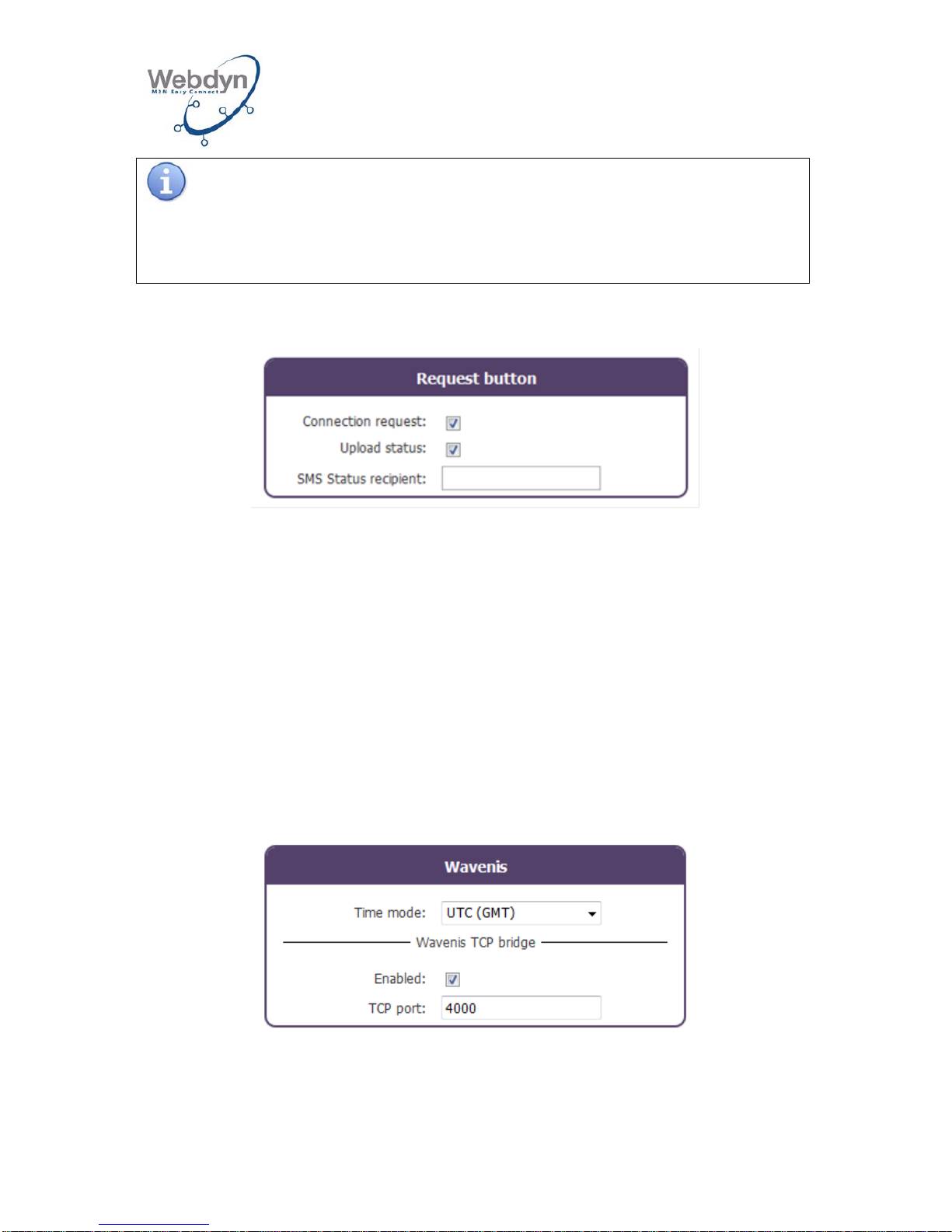
8.2.6 Request button
By default, pressing the Request button on the product’s front panel will trigger a
connection to the remote server and uploading of the data recorded as well as the
lodging of a status file. Both can be selectively deactivated.
A status SMS can also be sent to a specified recipient.
8.3 System configuration
8.3.1 Configuration of Wavenis parameters
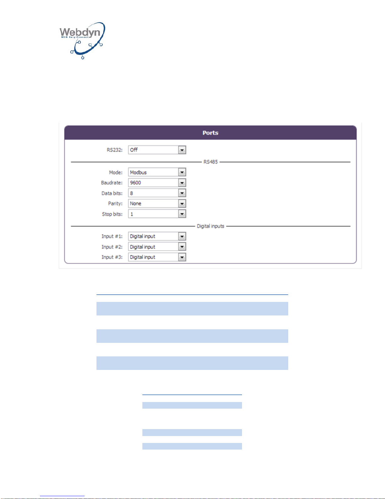
The management mode for the dates and times of the Wavenis modules enables the
way the dates and times are either sent or are to be sent to the modules to be
defined on the WebdynRF gateway.
The times of the modules can be managed:
- UTC (GMT): UTC time
- Local time with DST
- Local time w/o DST
The Wavenis bridge enables the gateway to be configured in Serial/IP mode in order
to use it as a Coronis WavePort via Ethernet.
Page 29
WEBDYN
WebdynRF
Installation Manual
WebdynRF – Installation Manual - Version 1.0 29
All you have to do is activate the Enabled box and specify the TCP port number to be
used.
Via Webdyn’s Toolbox, this configuration enables the Coronis Wavenet Monitor
software to be used to configure the Wavenis radio network (see section 8.6.2).
8.3.2 Ports configuration
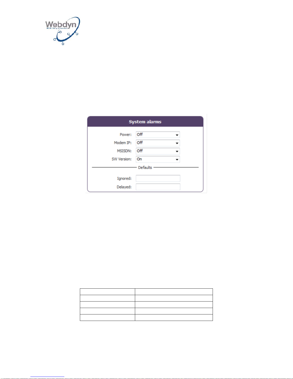
The gateway’s ports can be configured using the following parameters:
Port
Values
Description
rs232
Off
Mbus
RS232 deactivated
RS232 activated in MBus mode
rs485
Off
Modbus
RS485 deactivated
RS232 activated in MBus mode
Input #1/mode
Digital input
Pulse
Digital input mode
Pulse input mode
Input #2/mode
Digital input
Pulse
Digital input mode
Pulse input mode
Input #3/mode
Digital input
Pulse
Digital input mode
Pulse input mode
The parameters of the RS485 port are:
Name
Value
Mode
off, modbus
Baudrate
4800, 9600,
19200, 38400,
57600, 115200
Data bits
8
Parity
odd, even, none
stop_bit
1, 2
Page 30
WEBDYN
WebdynRF
Installation Manual
WebdynRF – Installation Manual - Version 1.0 30
8.4 Alarms configuration
The gateway can generate 3 types of alarm:
• System alarms.
• Wavenis alarms.
• On-off input alarms.
8.4.1 System alarms
There are 5 types of system alarms:
• Power: Alarm generated upon loss and return of the power supply.
• Modem IP: Alarm generated if the gateway’s IP address changes.
• MSISDN: Alarm generated if the SIM card inserted in the gateway is changed.
• SW Version: Alarm generated if the gateway’s firmware version changes
(during an update)
• Fault.
Each alarm source may be activated individually and be transferred immediately to
the remote server (On) or upon the next connection (Delayed).
The gateway also generates fault alarms, the codes of which are shown below:
Code
Description
D_MODEM
Modem fault
D_ETHERNET
Ethernet interface faul t
D_WAVENIS
Wavenis fault
D_INTERNAL_BAT
Internal battery fault
Each fault is transferred immediately to the remote server by the gateway.
Page 31
WEBDYN
WebdynRF
Installation Manual
WebdynRF – Installation Manual - Version 1.0 31
In the Ignored box, the fault codes ignored by the gateway can be listed. Should
several fault codes be entered, they must be separated by a ‘,’ (comma) character.
In the Delayed box, the fault codes listed transferred by the gateway upon the next
connection can be listed. Should several fault codes be entered, they must be
separated by a ‘,’ (comma) character.
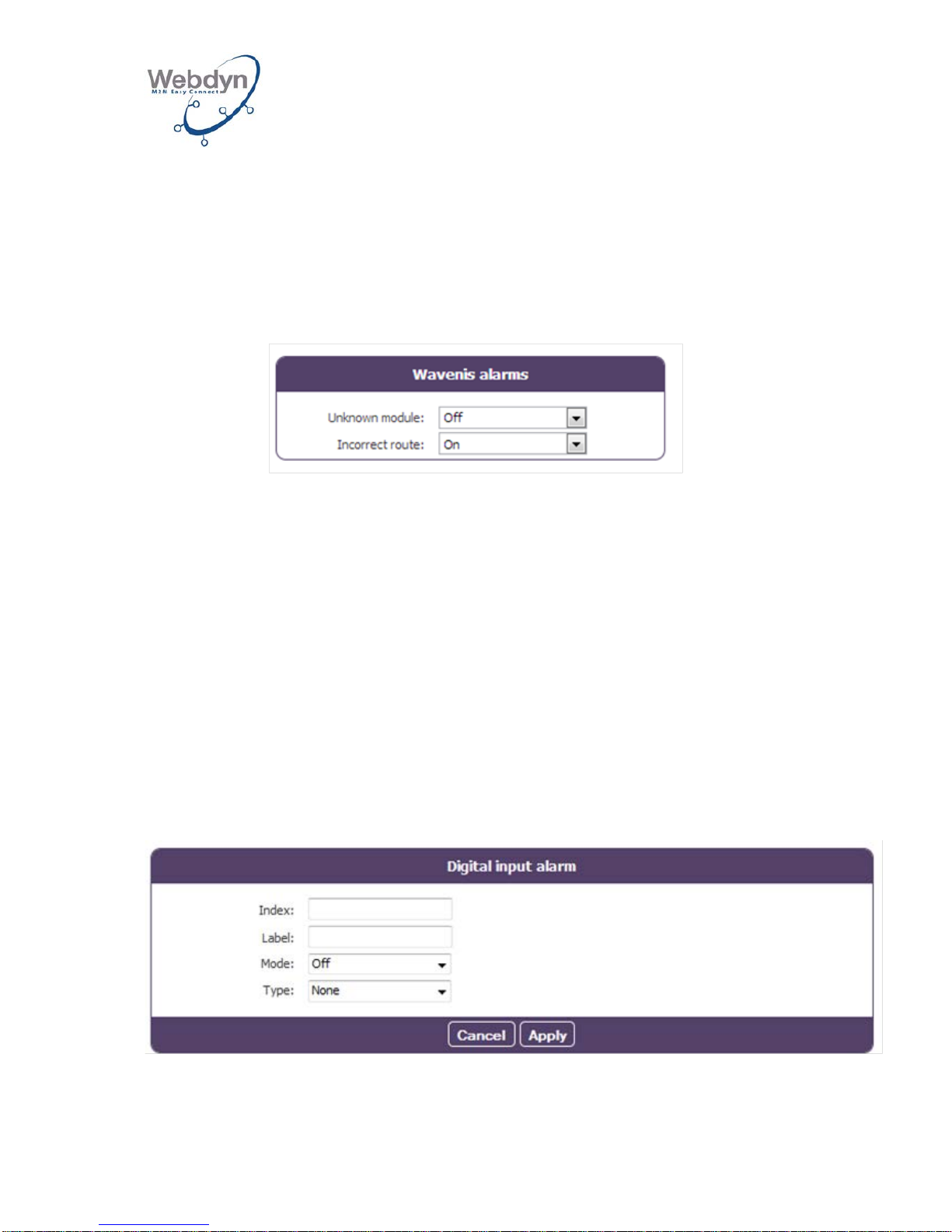
8.4.2 Wavenis alarms
When the gateway receives a Wavenis alarm message, it acknowledges it (to the
sending module).
If the alarm is triggered from a known module, the gateway processes it and then
initiates a connection to the remote server in order to lodge it.
If the alarm comes from an unknown module, a Wavenis_unknown alarm is triggered.
This alarm will be sent only once per module and may be sent immediately (On) or
upon the next connection (Delayed).
If the alarm is triggered from a known module but has followed a radio path that is
different from the one con fig ur ed, an Incorrect route alarm is triggered.
This alarm will be sent only once per module and may be sent immediately (On) or
upon the next connection (Delayed).
The gateway does not filter Wavenis alarms (in other words, there are no parameters
enabling the alarms for a given module to be selected). They may nevertheless be
activated and/or deactivated during configuration of the module itself.
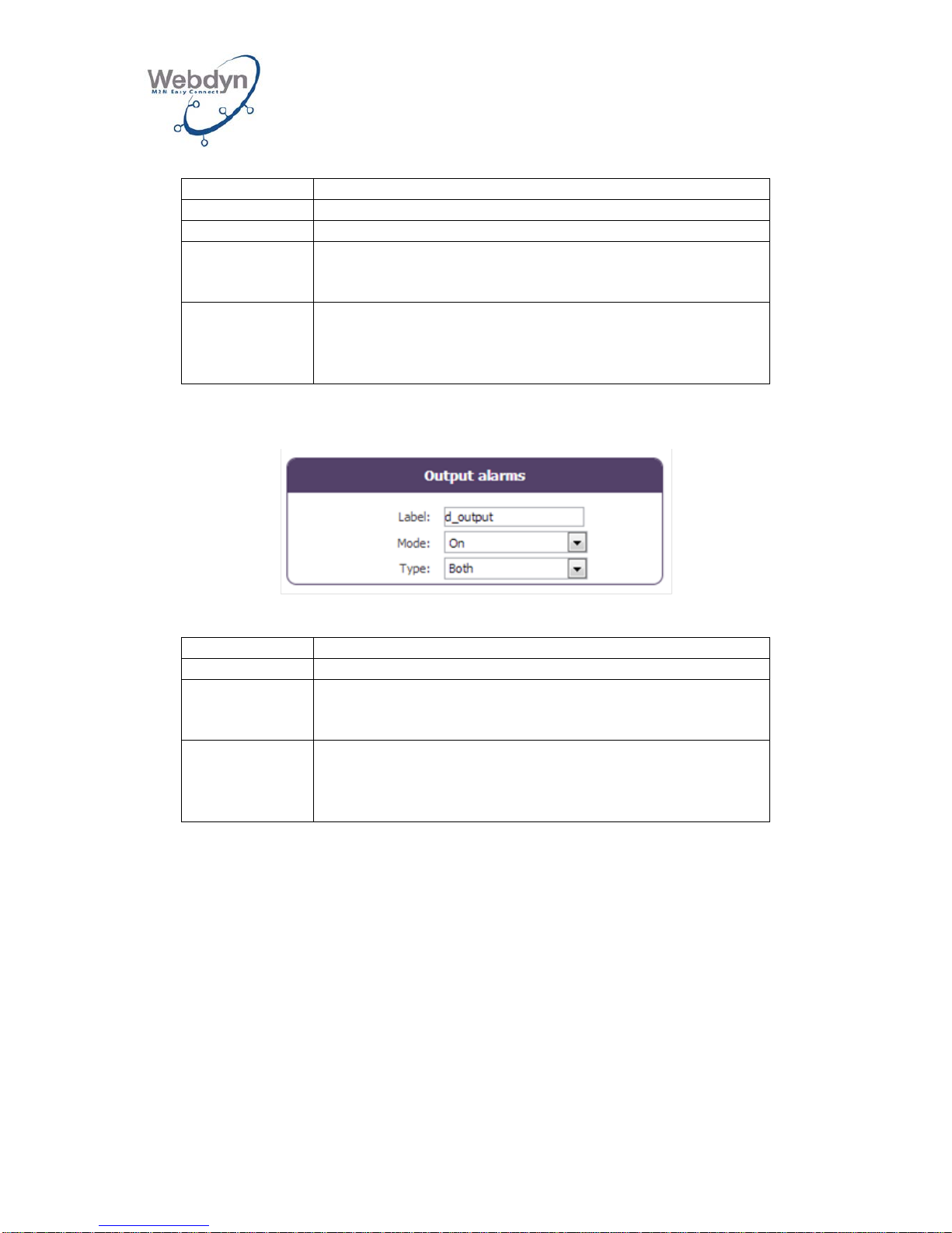
8.4.3 On-off input alarms
Multiple alarms may be configured for digital inputs.
An alarm for a digital input may be configured as follow s:
Page 32
WEBDYN
WebdynRF
Installation Manual
WebdynRF – Installation Manual - Version 1.0 32
Name
Description
Index
Index for the digital entry
Label
Name of the alarm (for information purposes only)
Mode
On: Immediate sending
Off: Sending deactivated
Delayed: Sending upon the next connection
Type
None: Detection deactivated
Rising: Rising edge detection
Falling: Falling edge detection
Both: Rising & Falling
8.4.4 On-off output alarms
An alarm may be configured for the digital output.
Name
Description
Label
Name of the alarm (for information purposes only)
Mode
On: Immediate sending
Off: Sending deactivated
Delayed: Sending upon the next connection
Type
None: Detection deactivated
Rising: Rising edge detection
Falling: Falling edge detection
Both: Rising & Falling
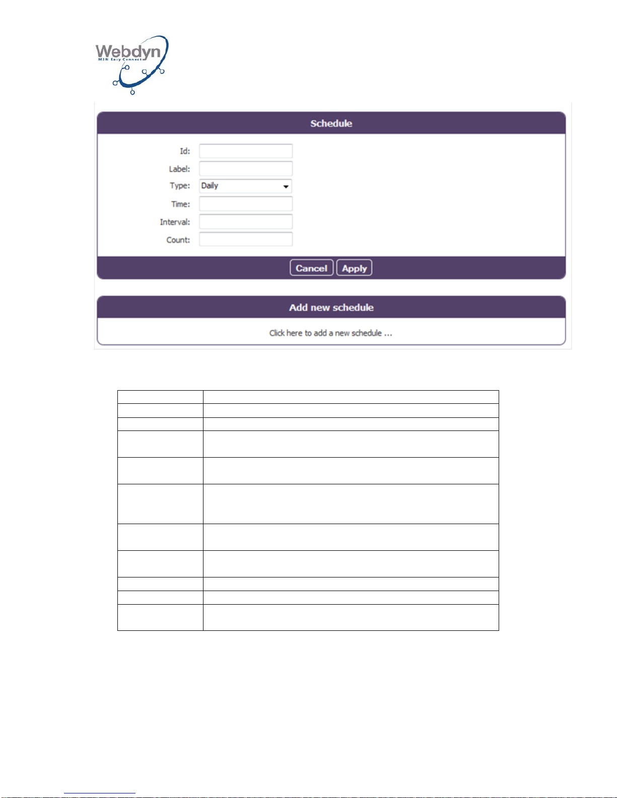
8.5 Schedules configuration
The scheduler is in charge of all the periodic tasks.
The configuration of the scheduler consists of a list of schedules.
Each of these schedules has a unique ID that is used to link a task to a precise
schedule. They may be used independently to trigger data gathering and to
download data.
Page 33
WEBDYN
WebdynRF
Installation Manual
WebdynRF – Installation Manual - Version 1.0 33
Each schedule is configured as follows:
Name
Description
Id
The schedule’s unique ID.
Label
Name of the schedule, for information purposes only.
Type
Daily, Weekly, Monthly, Yearly or Follower: see the
description below.
Time
Time of the first occurrence (not used for Yearly
schedules).
Day of Week
Number of the day of the week of the first occurrence (1
= Monday, 7 = Sunday) (used only for Weekly
schedules).
Day of Month
Number of the day of the month of the first occurrence
(used only for Monthly schedules).
Date & Time
Date and time of the first occurrence in a given period
(used only for Yearly schedules).
Interval
Interval between occurrences (in seconds).
Count
The number of occurrences.
Parent
Reference to the parent schedule for a Follower
schedule.
Configuration of the various types of schedules:
Daily schedule:
Every day, the first occurrence T0 is provided by the time filled in under Time.
The format of the time variable is as follows: HH:MM:SS. For example 09:30:00
Page 34

WEBDYN
WebdynRF
Installation Manual
WebdynRF – Installation Manual - Version 1.0 34
The next occurrences will occur at time Ti:
jour = day
∆t is the value in seconds filled in under interval.
Weekly schedule:
Every week, the first occurrence T0 is provided by the day of the week filled in under
dayofweek and the time, filled in under time.
The next occurrences will occur at time Ti:
semaine = week
∆t is the value in seconds filled in under interval.
Monthly schedule:
Every month, the first occurrence T0 is provided by the number of the day of the
month, filled in under dayofmonth, and the time, filled in under time.
The next occurrences will occur at time Ti:
mois = month
∆t is the value in seconds filled in under interval.
Yearly schedule:
Every year, the first occurrence T0 is provided by the date filled in under Date &
Time.
The format is as follows: YYYY-MM-DDTHH:MM:SS
For example, for a first occurrence on 11 February 2012 at 13H00:
Time = 2012-02-11T13:00:00.
The next occurrences will occur at time Ti:
année = year
∆t is the value in seconds filled in under interval.
Page 35

WEBDYN
WebdynRF
Installation Manual
WebdynRF – Installation Manual - Version 1.0 35
Follower schedule:
A “Follower” schedule will be produced after the end of each occurrence of the
reference schedule. Th e Parent schedule cannot be a "Follower" schedule.
This type, for example, enables the uploading of data to be triggered after completion
of a data gathering operation envisaged.
Example:
You want to gather data from all the Wavenis modules once a day at midnight and
download the data just after that. You can configure a “Daily” schedule for the data
gathering and a “Follower” schedule for the first schedule for uploading data.
Examples:
Need
Type
Time
Day of
Week
Day of
Month
Date & Time
Interval
Count
Every
Tuesday at
15:00:00
Weekly
15:00:00
2
0
1
Every 2nd
day of the
month at
00:00:00
Monthly
00:00:00
2
0
1
Every day at
14:00:00
Daily
14:00:00
0
1
Every hour
from 8H00 to
18H00 every
Tuesday
Weekly
08:00:00
2
3600
11
Every 2 hours
from 8H00 to
20H00 on 31
December
Yearly
2012-12-
31T08:00:00
7200
7
8.6 Configuration of the Wavenis radio network
Wavenis product versions
There are two ways of implementing the Wavenis radio network:
• If you already know the full Wavenis mapping, you can configure the modules
manually one by one by using the Wavenis table on the onboard Web
interface.
• If you wish to build your Wavenis network by using the gateway as a Waveport
and the Wavenet Monitor configuration tool, you can directly import the
configuration file from this Coronis tool.
The gateway supports the foll owing Wavenis modules:
• Waveflow (1, 2 and 4 inputs)
• Dallas Wavetherm (1 and 2 inputs), PT100 (1 input) and PT1000 (1 input)
• Wavesense 4-20mA (1 input) and 0-5V (1 input)
• Wavelog (2 and 4 inputs)
Page 36
WEBDYN
WebdynRF
Installation Manual
WebdynRF – Installation Manual - Version 1.0 36
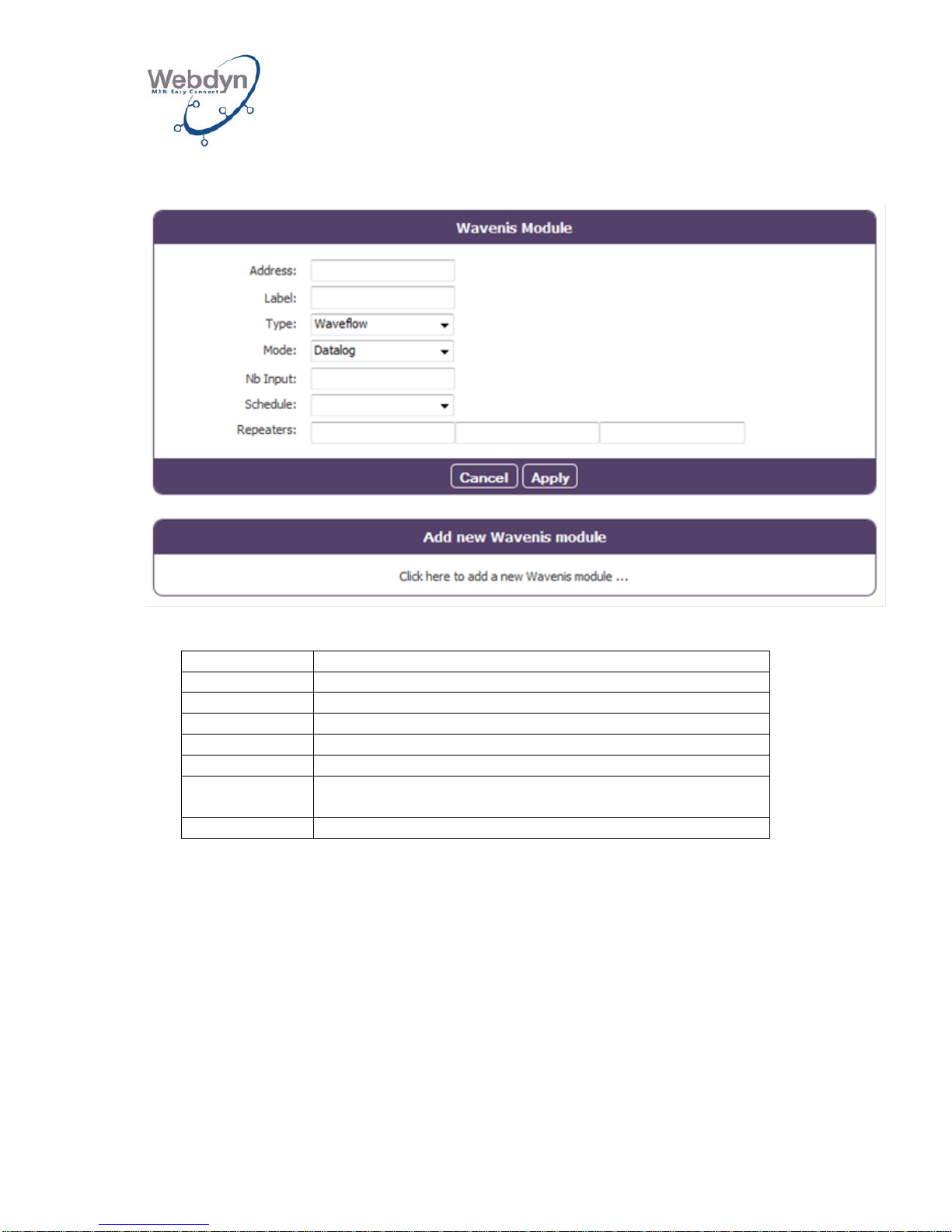
8.6.1 Configuration of the radio modules via the Web interface
Each module is configured as follows:
Name
Description
Address
Wavenis address
Label
Name of the module (for information purposes only)
Type
Type of module
Mode
Reading mode (immediate, datalog)
Nb Input
Number of module inputs
Schedule
Schedule’s unique ID used for the module reading (see
8.5)
Repeaters
List of the radio addresses of the repeaters
The Wavenis address may be entered in its hexadecimal form (12 digits) or in its
decimal form (15 digits, with an optional hyphen after the 5th and 7th figures).
The repeaters must be entered from the gateway to the module.
The modules associated with the same schedule are read in the order configured.
A request for a given module is repeated up to three times if necessary.
8.6.2 Configuration via the Wavenet Monitor and Toolbox software
The stages below explain how you can build your Wavenis network by using the
gateway as a Waveport with the Wavenet Monitor configuration tool and importing
the configuration file from this Coronis tool into the gateway.
Page 37
WEBDYN
WebdynRF
Installation Manual
WebdynRF – Installation Manual - Version 1.0 37
8.6.2.1 Installation of Com0Com
On the PC used, first of all you have to install Com0com.
This software makes it possible to create a pair of virtual ports which are connected
to each other via a virtual cable.
• Download the zip file from the following URL:
http://sourceforge.net/projects/com0com/
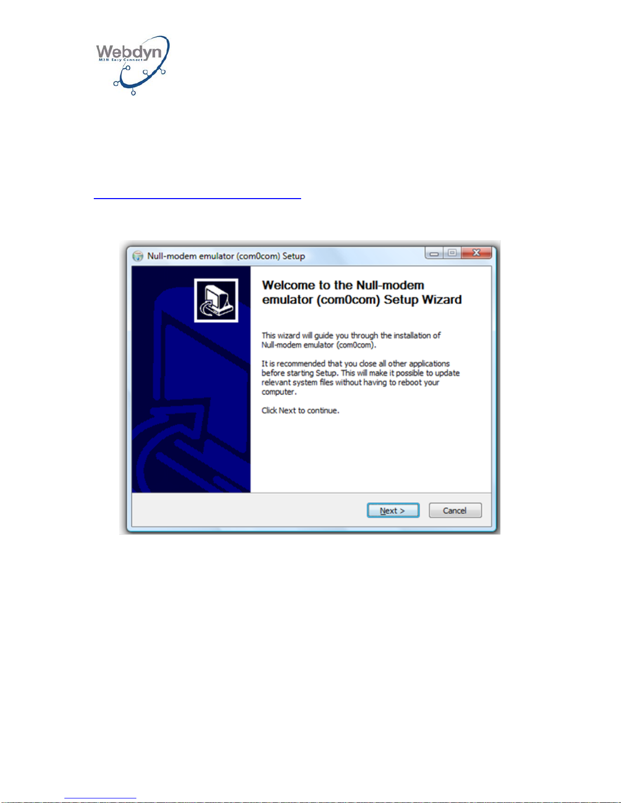
• Launch setup.exe. and follow the installation stages:
• Click on Next.
Page 38
WEBDYN
WebdynRF
Installation Manual
WebdynRF – Installation Manual - Version 1.0 38
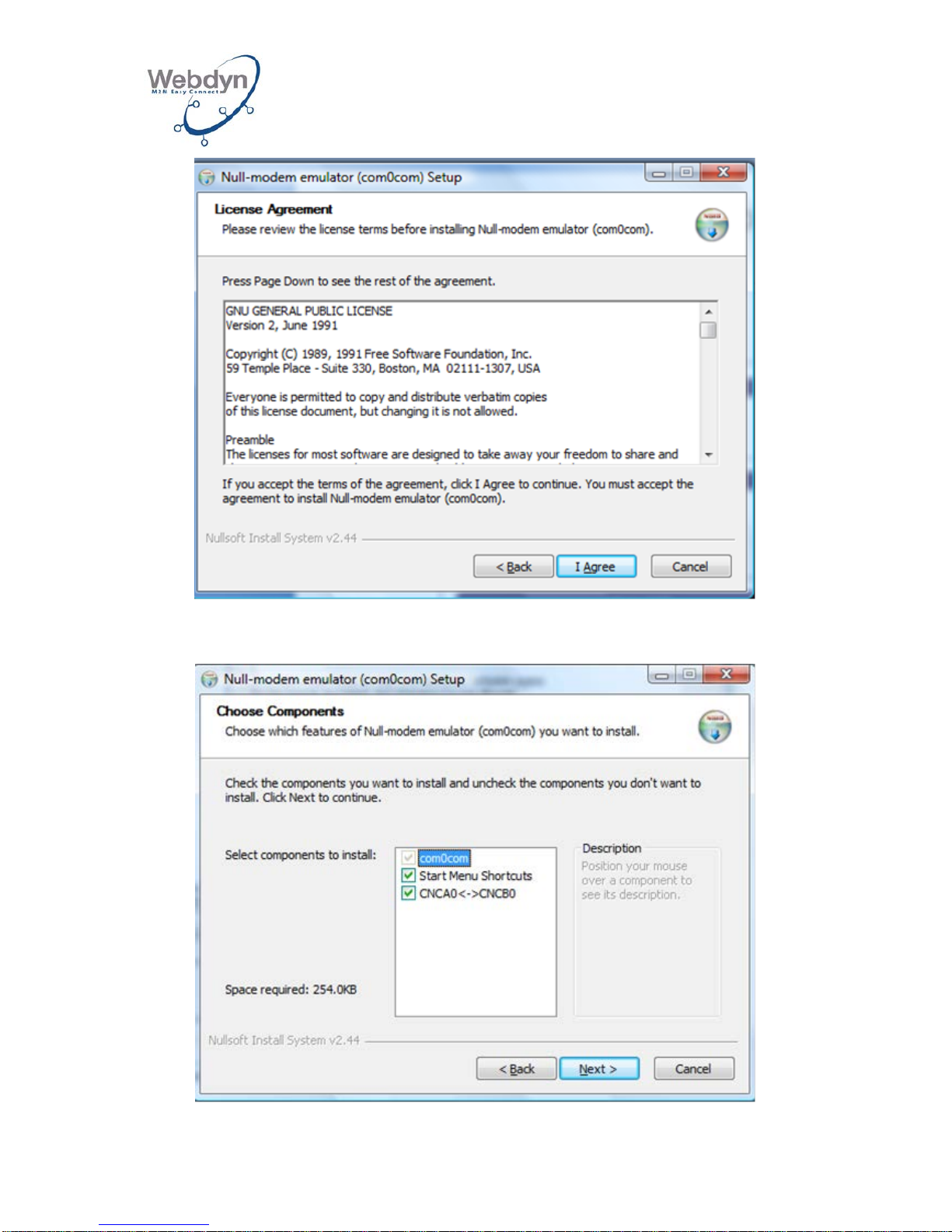
• Click on Agree.
Page 39
WEBDYN
WebdynRF
Installation Manual
WebdynRF – Installation Manual - Version 1.0 39
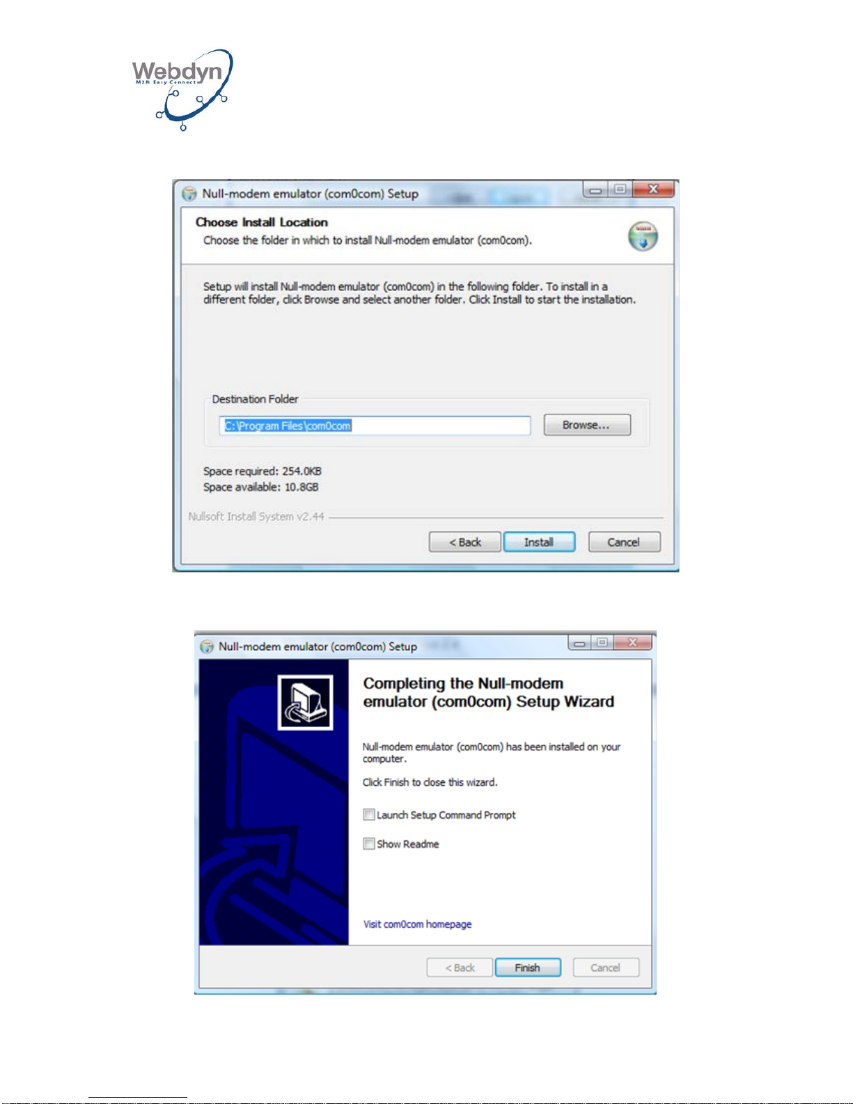
• Click on Next.
• Fill in an installation directory and click on Install:
Page 40
WEBDYN
WebdynRF
Installation Manual
WebdynRF – Installation Manual - Version 1.0 40
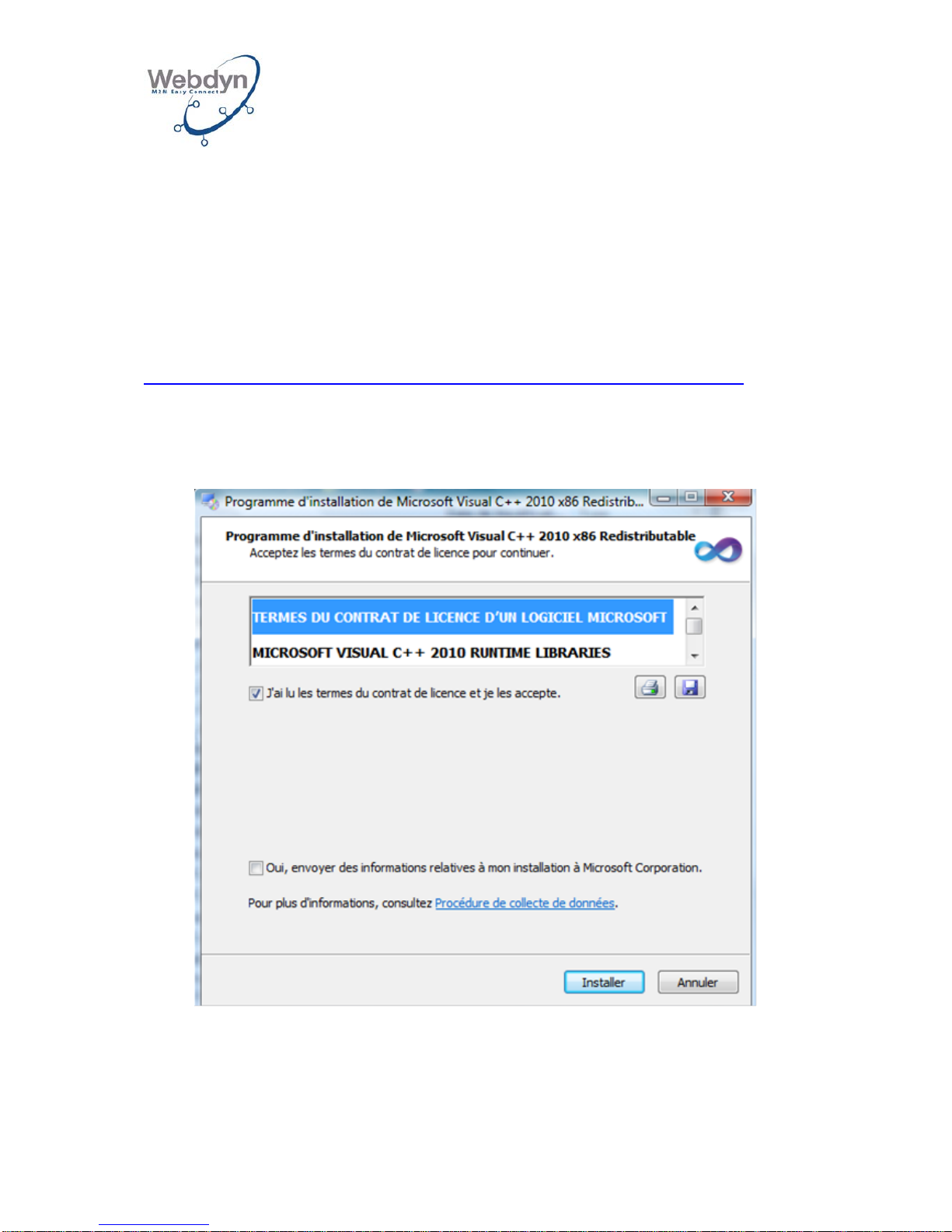
• Once the installation is completed, click on Finish:
8.6.2.2 Installation of Visual C++ libraries
To enable the Toolbox to function, you have to install the Microsoft Visual C++ 2010
Redistributable Package (x86) plug-in.
• Download the plug-in from the following URL:
http://www.microsoft.com/download/en/details.aspx?displaylang=en&id=5555
• Launch vcredist_x86.exe.
• Click on Install:
• Once the installation is completed, click on Finish:
Page 41

WEBDYN
WebdynRF
Installation Manual
WebdynRF – Installation Manual - Version 1.0 41
8.6.2.3 Toolbox installation
You can download Toolbox from the fol lowing URL:
http://www.webdyn.com/wp-content/uploads/2011/10/WRF_Toolbox.zip
You then have to extract the zip file into a directory of your choice.
The following files will be created:
Page 42
WEBDYN
WebdynRF
Installation Manual
WebdynRF – Installation Manual - Version 1.0 42
8.6.2.4 Using the gateway with Wavenet Monitor
To use the gateway as a Waveport and to put together the Wavenis radio mapping
using the Wavenis Monitor software, follow these steps:
• Connect your PC via Ethernet to the gateway (see section 6.1).
• Activate the Wavenis TCP Bridge mode and specify a TCP port (see section
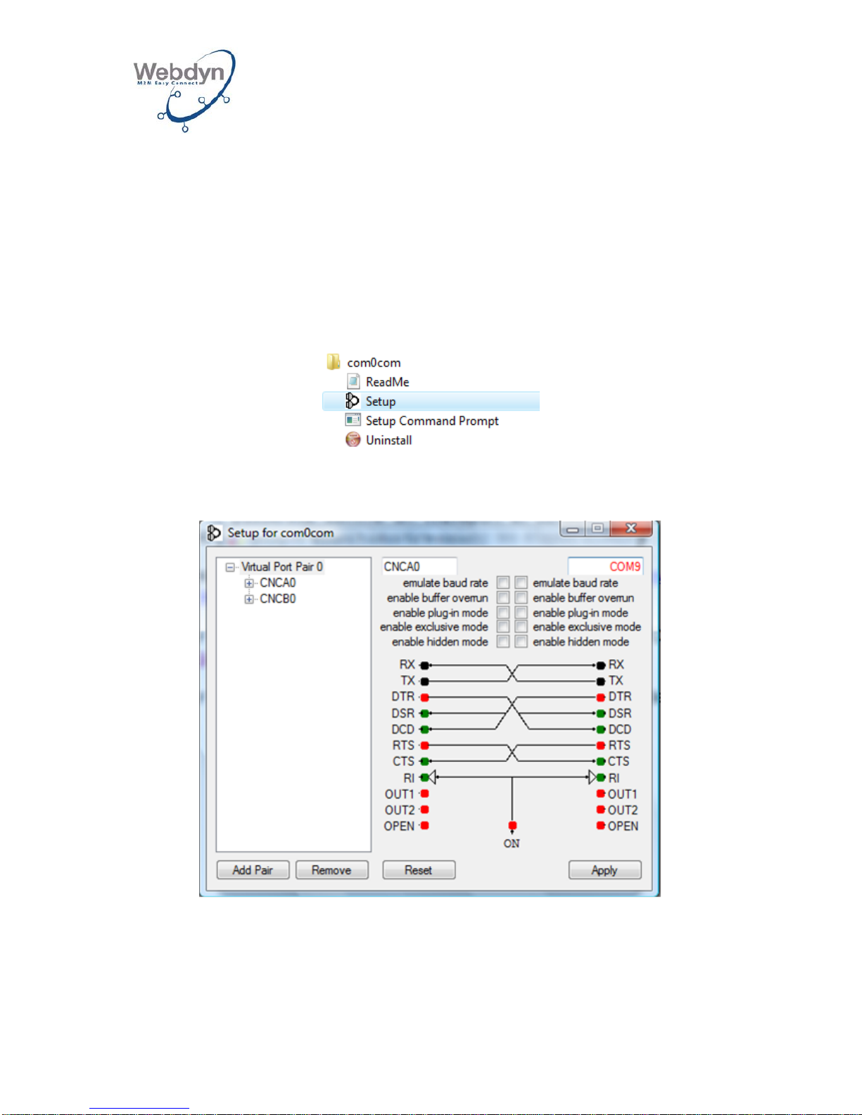
8.2.6).
• Launch the com0com setup featured in the Windows Start menu:
• Rename the CNCA1 port as a serial port name from the available names
ranging from COM1 to COM9 (for example COM9):
• Click on Apply and on Continue:
Page 43
WEBDYN
WebdynRF
Installation Manual
WebdynRF – Installation Manual - Version 1.0 43
• Close the com0com tool.
• Launch the Toolbox by executing WRFtoolbox.exe.
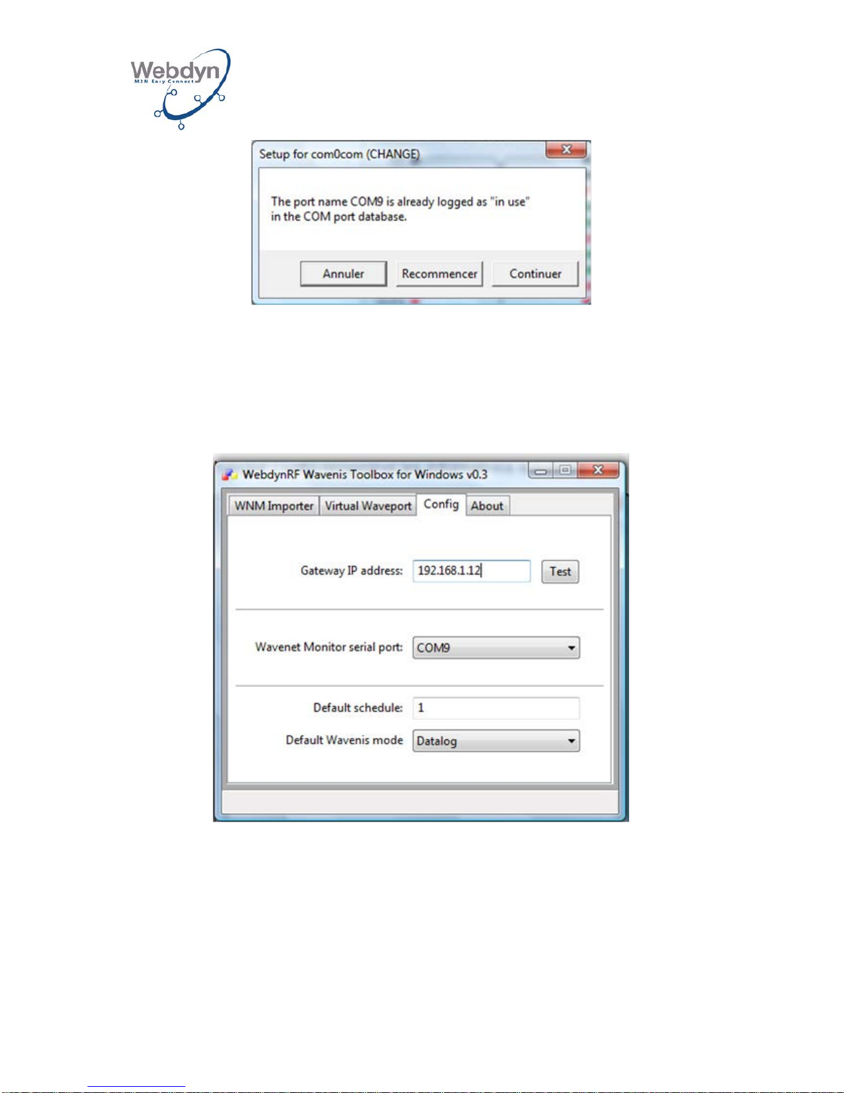
• In the Config tab, fill in the following pieces of informat ion:
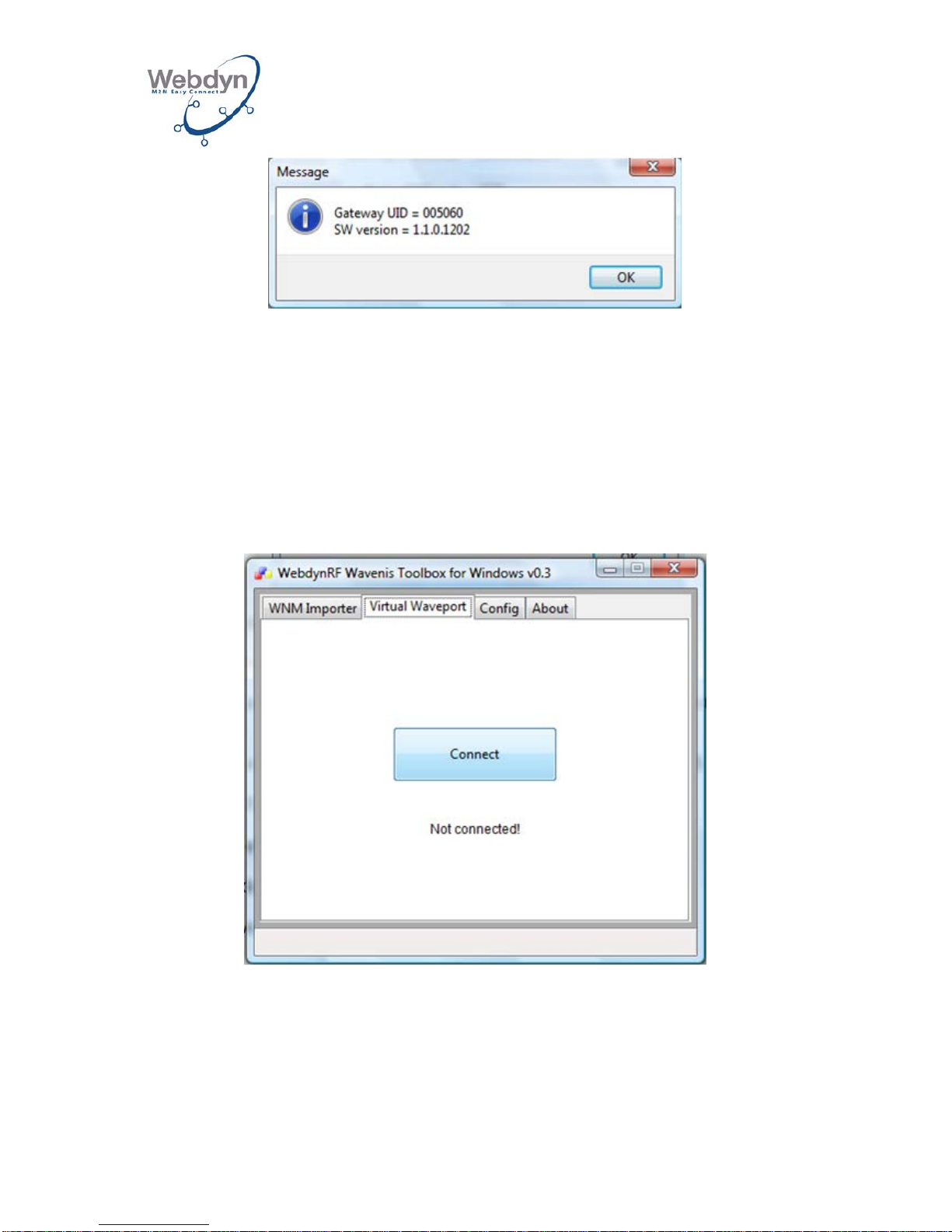
o The gateway’s IP address. You can test the TCP communication with
the gateway by clicking on Test. If there is functional communication,
the gateway will return its UID and its software version:
Page 44
WEBDYN
WebdynRF
Installation Manual
WebdynRF – Installation Manual - Version 1.0 44
o The TCP port configured in the gateway.
o The COM port configured in com0com.
o The schedule’s unique ID to be applied to all the modules (see
section 8.5).
o The modules reading mode (Datalog or Immediate).
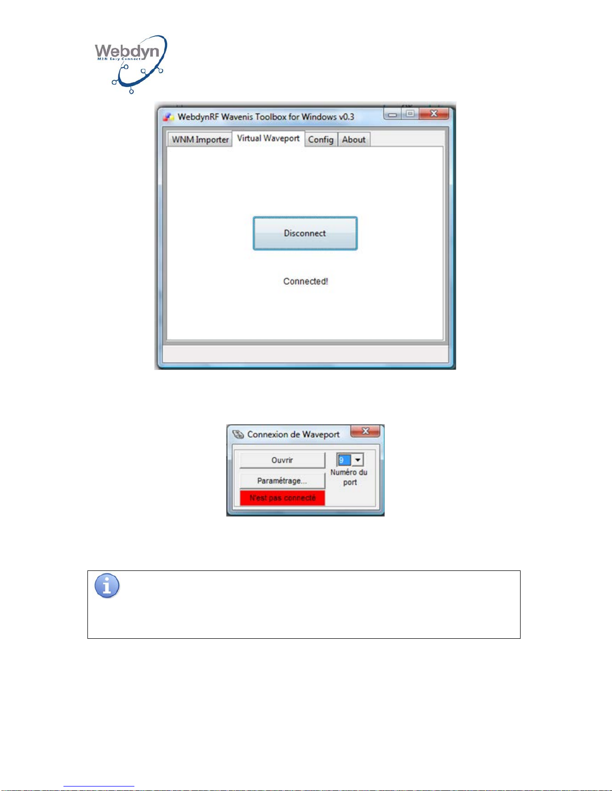
• In the Virtual Waveport tab, click on Connect:
• This means that the PC is connected to the gateway via the virtual serial port:
Page 45
WEBDYN
WebdynRF
Installation Manual
WebdynRF – Installation Manual - Version 1.0 45
• You can now use Wavenet Monitor by configuring the virtual COM port (COM9
in our example) within the Waveport connection:
• Click on Open.
• This enables you to build the Wavenis network.
Consult the Wavenet Monitor software’s Coronis documentation in order to
put together the Wavenis mapping.
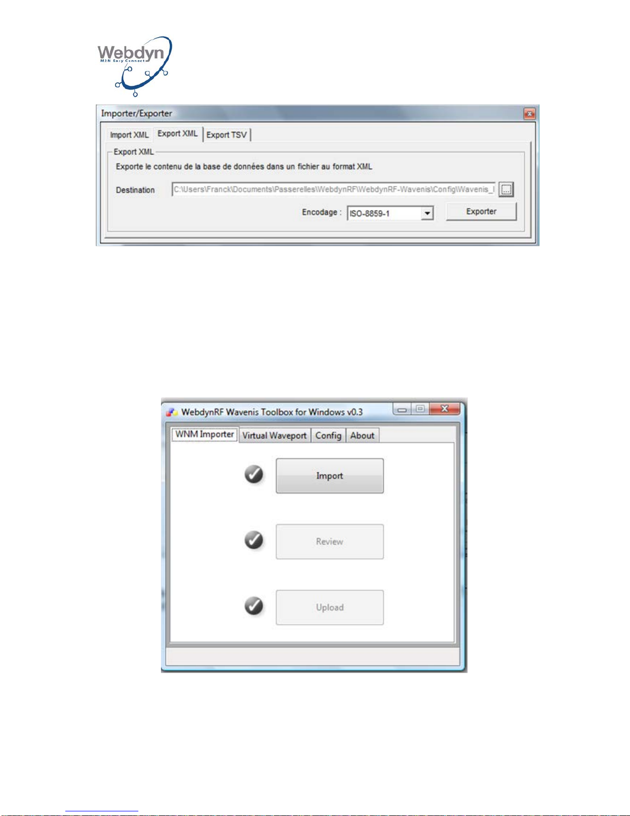
• Once the Wavenis network is configured in Wavenet Monitor, you must export
the following in an XML file:
Page 46
WEBDYN
WebdynRF
Installation Manual
WebdynRF – Installation Manual - Version 1.0 46
8.6.2.5 Importing the Wavenis configuration into the gateway
Once your Wavenis network has been built and exported in the form of a Wavene t
Monitor XML file, you have to import it into the gateway by using Toolbox.
To do that, carry out the following steps:
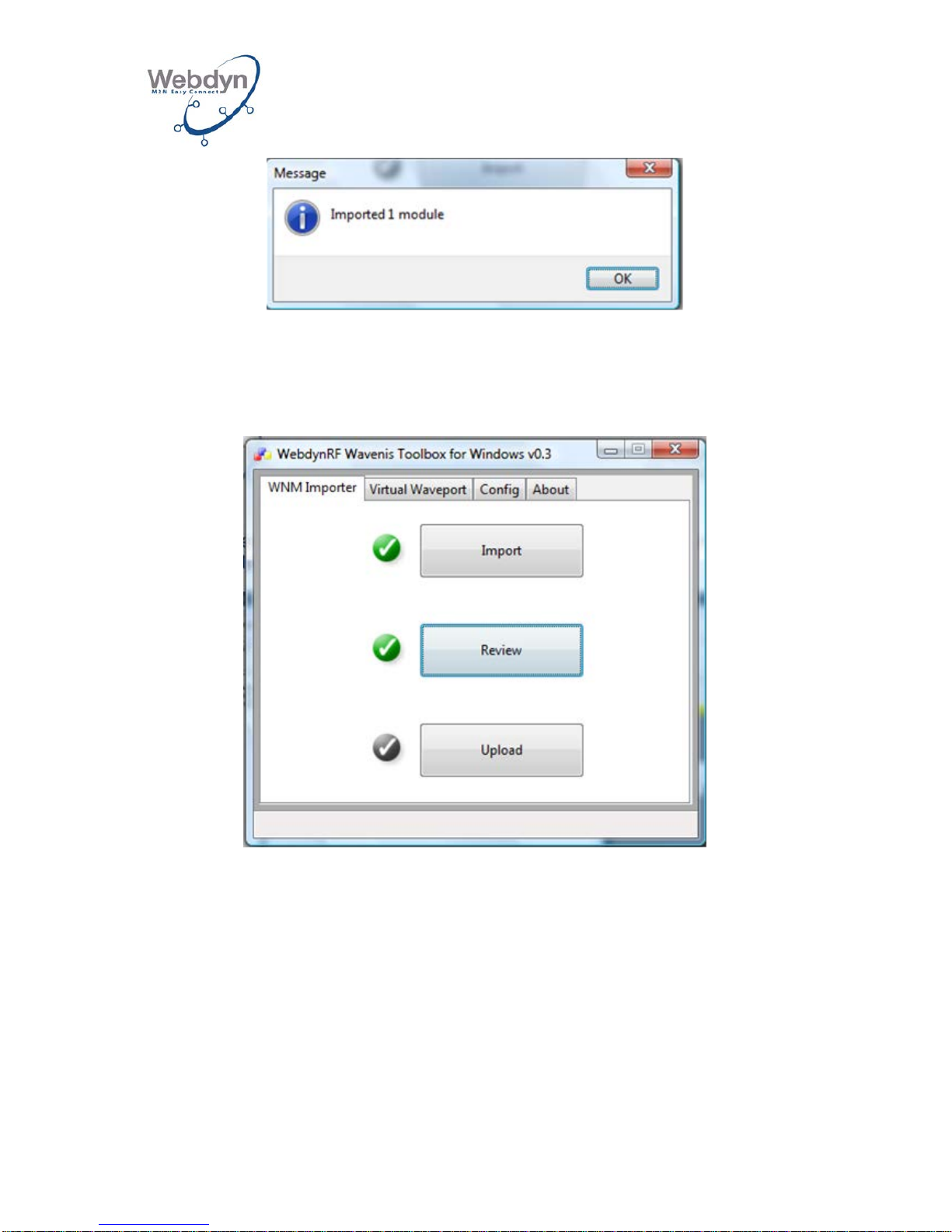
• Import the XML file into the gateway using Toolbox: click on Import on the
WNM Importer tab:
• A window will be displayed, indicating the number of modules imported:
Page 47
WEBDYN
WebdynRF
Installation Manual
WebdynRF – Installation Manual - Version 1.0 47
• Click on Review to view the configuratio n file i n Webdy nRF form at:
• Click on Upload to transfer the configuration file onto WebdynRF:
You can check whether modules are present on the onboard Web page’s Wavenis
tab.
8.7 Metering configuration
8.7.1 Pulse inputs
Page 48
WEBDYN
WebdynRF
Installation Manual
WebdynRF – Installation Manual - Version 1.0 48
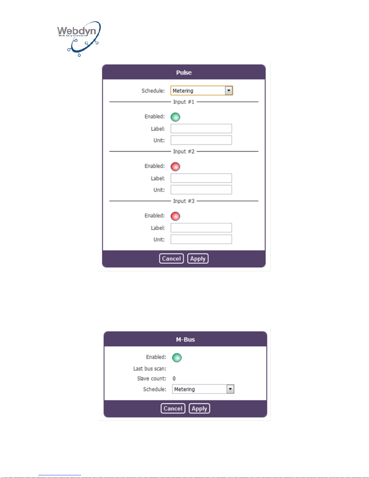
Digital inputs may be selectively configured as pulse meters (see section 8.3.2). Once
the input is activated, an associated meter will increase incrementally after each
pulse lasting more than 10ms. The current value will be saved for each occurrence of
the schedule specified.
The unit and label parameters are added to the data saved with the index value.
8.7.2 M-Bus
Page 49
WEBDYN
WebdynRF
Installation Manual
WebdynRF – Installation Manual - Version 1.0 49
If the RS232 port is configured in MBus mode (see section 8.3.2), acquisition may be
activated using the associated schedule.
8.7.3 169 MHz Wireless Mbus
169MHz Wireless Mbus product versions
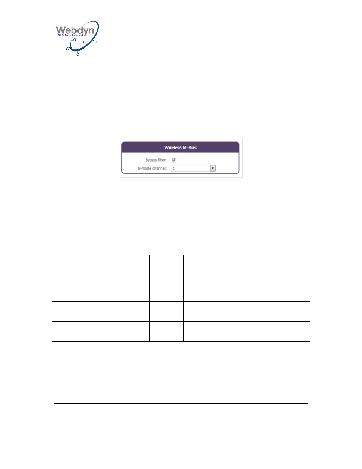
The 169MHz Wireless M-Bus radio card version of the WebdynRF gateway may
receive data from known Wireless M-Bus modules (filtering activated), or may not (if
the filtering is deactivated).
The interface enables the filtering of the modules to be activated or deactivated and
enables the N mode channel used to be selected.
8.2 N mode – Physical link parameters
The sub-modes must be assigned to the channels and frequencies as described in Table 18.
Table 18 – N mode - Frequencies
Sub-
mode Channelb
Central
frequency
[MHz]
Channels
separation
[kHz]
GFSK
[kbps]
GMSK
[kbps]
4GFSK
[kbps]
Frequency
tolerance
[± kHz]
N1a, N2a
1ac
169.406250
12.5
4.8 1.5
N1b, N2b
1b
169.418750
12.5
4.8 1.5
N1c, N2c
2a
169.431250
12.5
2.4
2.0
N1d, N2d
2b
169.443750
12.5
2.4
2.0
N1e, N2e
3a
169.456250
12.5
4.8 1.5
N1f, N2f
3bc
169.468750
12.5
4.8 1.5
N2g
0d
169.437500
50
38.4
4.25 a 1
169.412500
25
a
2 169.437500
25
a
3 169.462500
25
a
These channels are optional and are reserved for future use of uses specific to the country concerned.
b
Designation of the channels in accordance with EU Commission decision 2005/928/EC.
c
Use of these channels must be given priority should there be a need to retransmit the data transmitted by the meter.
d
This channel may be used for retransmitting metering data on a multi-hop basis, as specified in EN 13757-5. The load factor
for the transmission from the meter must be limited to 0.02% on this channel.
Extract from standard EN 13757-4
Page 50
WEBDYN
WebdynRF
Installation Manual
WebdynRF – Installation Manual - Version 1.0 50
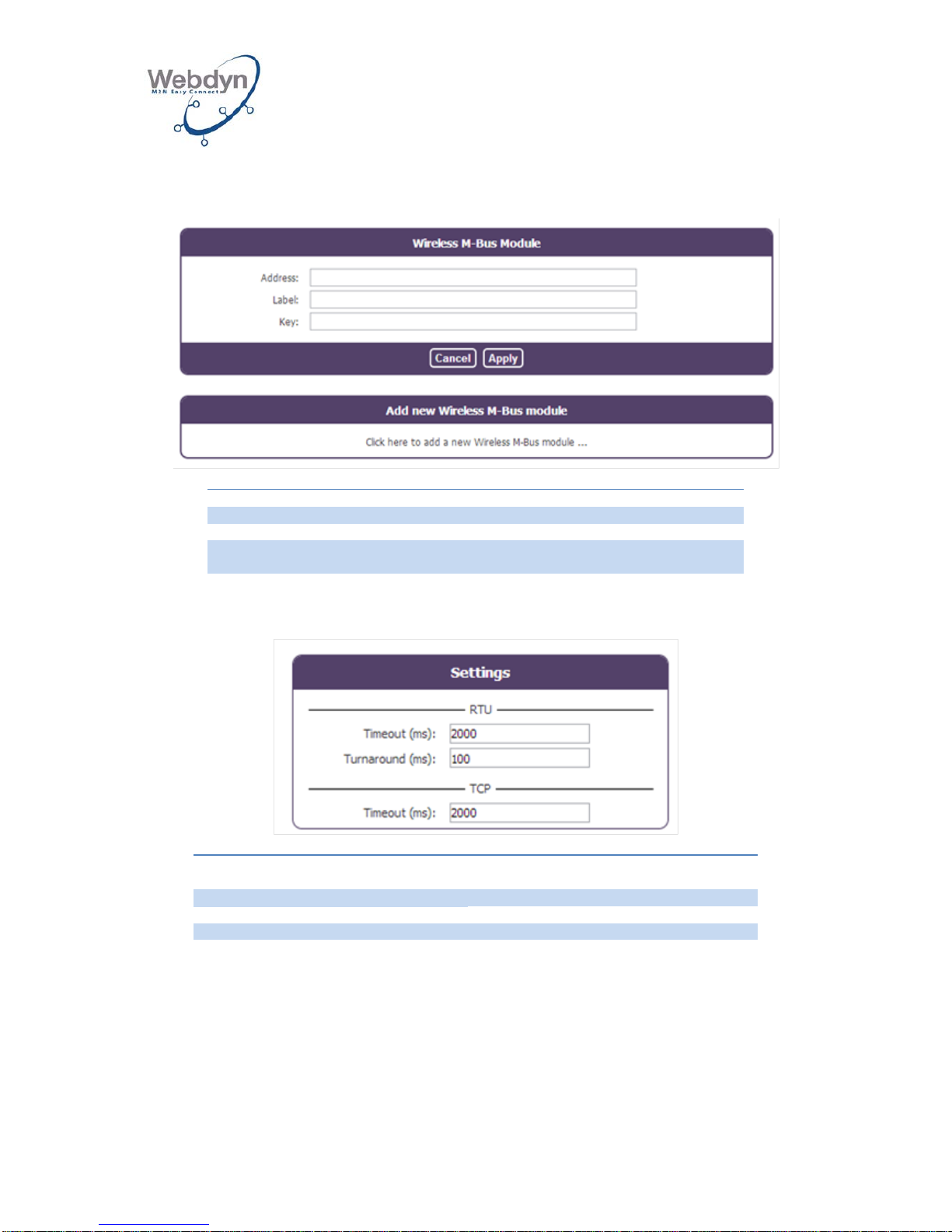
If the filtering is activated, the modules configuration is carried out using the following
interface:
Name
Description
Address
Wireless M-Bus address
Label
Name of the module (for information purposes only)
Key
Encryption key for the module (if it is blank, there is
no encryption)
8.8 Modbus configuration
Name
Description
RTU
Timeout (ms)
Modbus/RTU response timeout in ms
Turnaround (ms)
Modbus/RTU turnaround delay in ms
TCP
Timeout (ms)
Modbus/TCP response timeout in ms
As a supplement to these parameters, the port must be configured as “modbus” (see
section 8.3.2).
Page 51
WEBDYN
WebdynRF
Installation Manual
WebdynRF – Installation Manual - Version 1.0 51
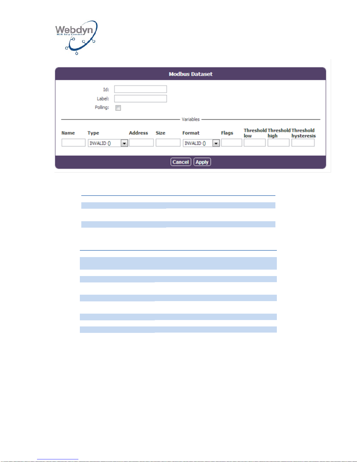
The configuration of a dataset consists of configuring the following parameters:
Name
Description
Id
Unique ID for the Modbus dataset
Label
Name of the dataset (for information
purposes only)
Polling
Continuous polling (true or false)
Each variable is defined by the following parameters:
Name
Description
Name
Name of the variable (for information purposes
only)
Type
Type of variable (S0, S1, S3, S4)
Address
16-bit extended register address
Size
Size in bits for discrete input and coil, in bytes
for the registers
Format
Raw, Boolean, integer, float or ASCII
Flags
cmd_only, little_endian, no_opt, is_status or
is_alarm
Threshold low
Low threshold level
Threshold high
High threshold level
Threshold hysteresis
Hysteresis applied to both thresholds
For the configuration details, see the operating manual.
Page 52
WEBDYN
WebdynRF
Installation Manual
WebdynRF – Installation Manual - Version 1.0 52
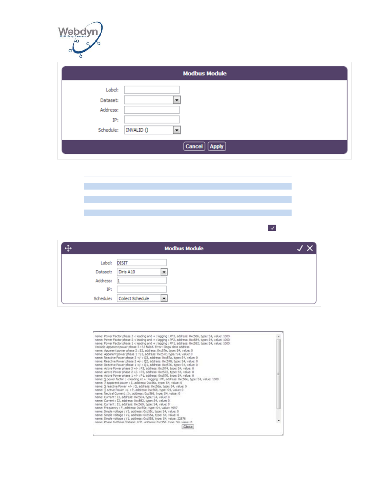
The configuration of a Modbus mo dul e incl ud es th e following parameters:
Name
Description
Label
Name for information purposes only
Dataset
Dataset ID
Address
Modbus address (1-247)
IP
IP address (blank for RTU equipment)
Schedule
Schedule ID
To verify the right configuration for a Modbus module, you can press :
The result of the Modbus module query will be displayed in a window:
Page 53
WEBDYN
WebdynRF
Installation Manual
WebdynRF – Installation Manual - Version 1.0 53
8.9 Executable actions
8.9.1 Request for connection to the remote server
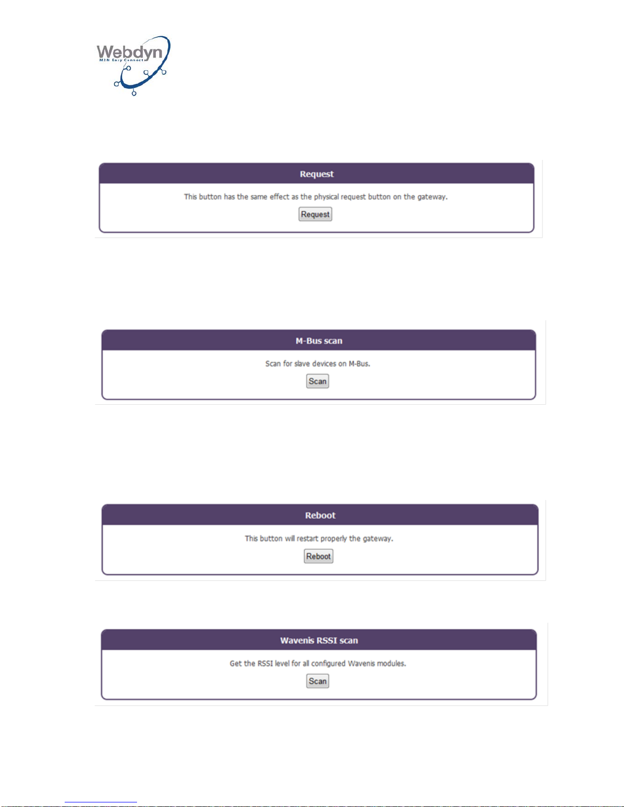
This button has the same effect as the physical button featured on the product’s front
panel. A pop-up window will appear that displays all of the connection stages, and
particularly the NTP synchronization and the Inbox directory verification, and
indicates all the files downloaded.
8.9.2 M-Bus scan request
A scan of the M-Bus equipment can be launched using this button. The M-Bus
equipment discovered during this scan will be queried upon each occurrence of the
associated scheduler. If equipment items are removed from the bus or added to it, a
new scan must be initiated so that the gateway may take the modification into
account.
8.9.3 Reboot request
This button enables the gateway to be restarted properly.
8.9.4 Wavenis RSSI scan request
Page 54
WEBDYN
WebdynRF
Installation Manual
WebdynRF – Installation Manual - Version 1.0 54
A scan of the RSSI values of all the Wavenis modules can be triggered using this
button. A pop-up window will display the RSSI values and a list indicating the
modules that could not be connected to.
8.9.5 Uploading system files
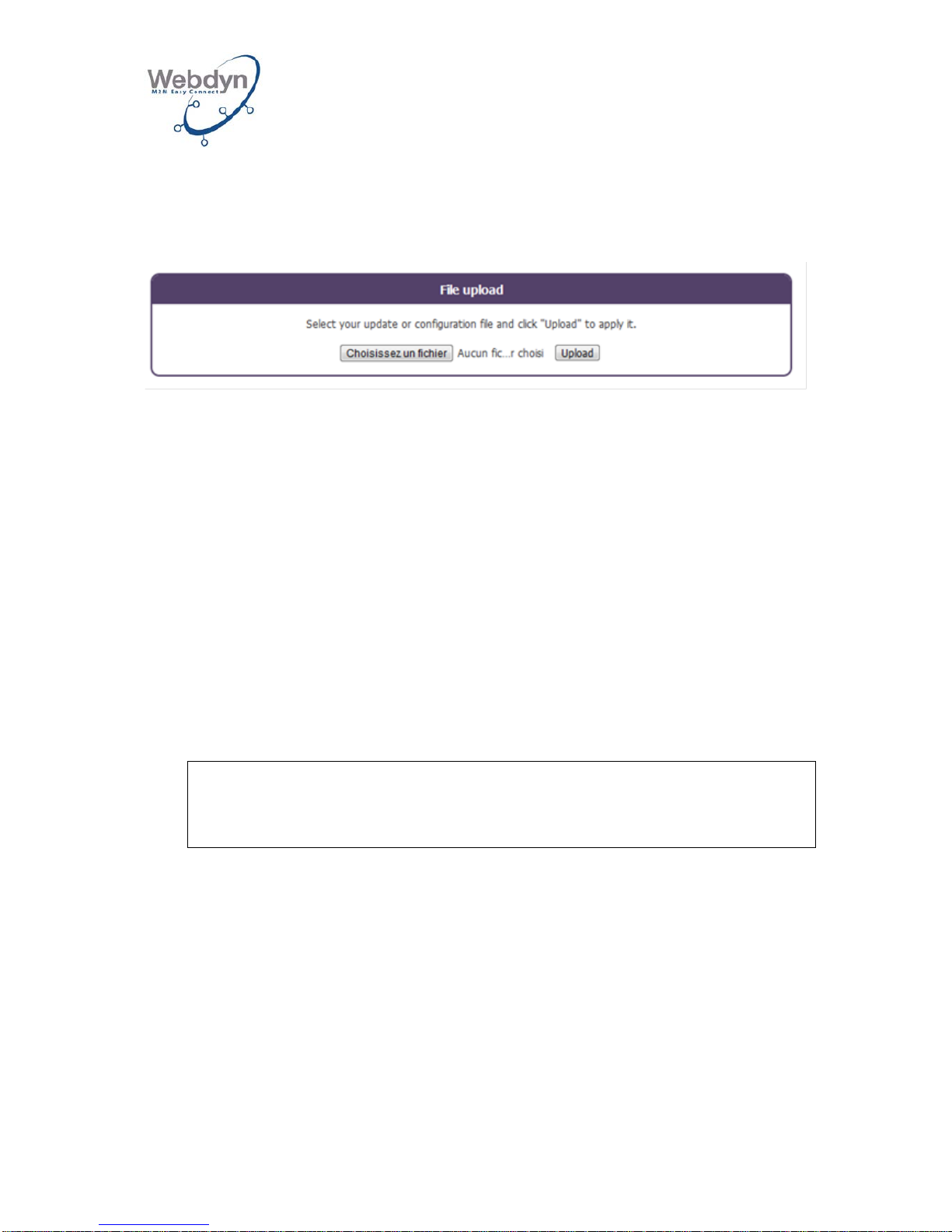
This window makes it possible to perform local uploading of configuration files or new
firmware onto the gateway.
8.10 Request for connection to the remote server
Once configuration has been carried out, you must prompt the gateway’s connection
to the remote server by briefly pressing the REQUEST button.
The GSM LED will light up while GSM connection is in progress.
9 Check on the gateway’s smooth runni ng
To check that the gateway and the radio mapping are running smoothly, you can
trigger a scan of the Coronis modules and the lodging of a Supervision file.
There are two solutions for doing this:
- If you have access to the remote server, put a scan command in the INBOX
directory.
Below is an example of a scan XML command:
<commands>
<cmd cid=’Install’>
<scan mode=’rtc life-counter rssi data’/>
</cmd>
</commands>
This command triggers:
o A reading of the clock, the status of the battery, the RSSI level, and the
immediate data for each module configured.
o Lodging of the supervision file containing this information (except for the
immediate data).
o Lodging of the Wavenis data file containing the immediate data.
Once this command file is put on the remote server in the INBOX directory,
you must prompt the gateway’s connection to the remote server by briefly pressing
the REQUEST button.
Page 55
WEBDYN
WebdynRF
Installation Manual
WebdynRF – Installation Manual - Version 1.0 55
- If you do not have access to the remote server so that this operation can be
triggered, you can carry it out via SMS.
SMS to send to the gateway:
cmd=scan
cid=Install
mode=rtc,life-counter,rssi,data
The data requested (except for the immediate data) will be uploaded onto the remote
server as supervision data using the corresponding configured downloading method.
The immediate data (scan data) will be uploaded onto the remote server as Wavenis
data using the corresponding configured uploading method.
Once the gateway has lodged the data, you can check the information fed back.
Consult the gateway’s operating manual for the m anagement instructions for
the data exchanged by the gateway with the remote server (cf. ME-WebdynRFWavenis.pdf)
10 Local FTP server
The gateway has an onboard local FTP server. It functions as a local INBOX. One
single file may be put on this server at a time.
It accepts configuration files and binary files for updating purposes.
11 Shutting down the WebdynRF gate w a y
Disconnect the 12/24V connector’s power supply cable.
The WebdynRF gateway is equipped with a back-up battery. Upon losing its power
supply, it sends an alert to the server and then continues functioning until the battery
is flat.
12 Support
Should you experience technical issues relating to our products, please contact
Webdyn’s support service:
Webdyn SA
26 Rue des Gaudines
78100 Saint-Germain-en-Laye
FRANCE
Tel.: +33 1 39 04 29 40
Fax.: +33 1 39 04 29 41
E-mail: [email protected]
http://www.webdyn.com
Page 56

WEBDYN
WebdynRF
Installation Manual
WebdynRF – Installation Manual - Version 1.0 56
We will need the following details:
• The gateway’s serial number.
• The gateway’s hardware and software versions.
 Loading...