

Page 1
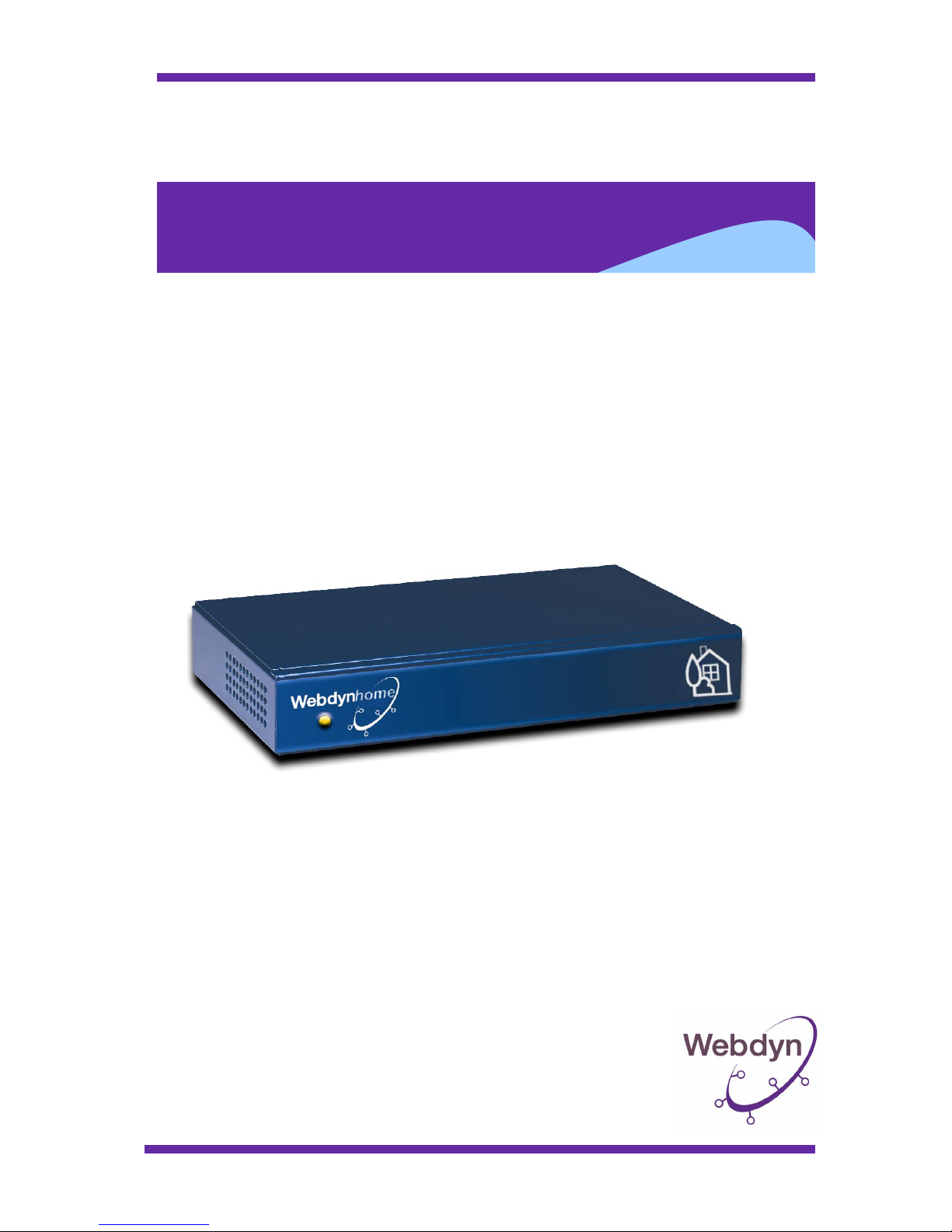
Webdynhome Installation Guide
Webdynhome
Version 2.01
December 2003
Page 2

Page 2
Table of contents
1 INTRODUCTION................................................................................................. 5
1.1 Terminology .............................................................................................................................. 6
1.2 Types of information managed ............................................................................................... 6
1.3 Types of actions ....................................................................................................................... 6
1.4 User types ................................................................................................................................. 7
2 DOCUMENT ORGANIZATION ........................................................................... 8
3 THE WEBDYNHOME CONCEPT ....................................................................... 9
3.1 What is the Webdynhome? ..................................................................................................... 9
3.2 The native Web site .................................................................................................................. 9
3.3 Control....................................................................................................................................... 9
3.4 Sequences............................................................................................................................... 10
3.5 Alarms ..................................................................................................................................... 11
4 SAFETY ............................................................................................................ 12
4.1 General electrical safety ........................................................................................................ 12
4.2 Protection against electrical discharges ............................................................................. 12
4.3 Additional safety information................................................................................................ 12
5 PHYSICAL INSTALLATION PROCEDURES................................................... 13
5.1 Physical installation ............................................................................................................... 14
5.1.1 Rear connectors .................................................................................................... 14
5.1.2 Digital input characteristics:................................................................................. 14
5.1.2.1 Webdynhome Input/Output pinouts :............................................................... 14
5.1.2.2 Connector specifications .................................................................................. 15
5.1.2.3 Wiring procedure.............................................................................................. 15
5.1.3 Output characteristics:.......................................................................................... 16
5.1.4 RS232 COM1 Interface........................................................................................ 16
5.1.5 RS232 COM2 Interface........................................................................................ 16
5.1.6 Network Connection ............................................................................................ 17
5.1.6.1 Webdynhome Ethernet connector pinouts ....................................................... 17
5.2 Before powering up the system............................................................................................ 17
Page 3

Page 3
6 INITIAL SYSTEM INSTALLATION PROCEDURES......................................... 18
6.1 Initial contact with the Webdynhome ................................................................................... 18
6.2 Network Configuration...........................................................................................................22
6.3 DHCP Configuration............................................................................................................... 23
6.4 SMTP (email) configuration ................................................................................................... 26
6.5 User profile configuration ..................................................................................................... 27
6.6 Setting the system data and time ......................................................................................... 30
6.7 Alarms Configuration............................................................................................................. 30
7 ENVIRONMENT EQUIPMENT CONFIGURATION........................................... 34
7.1 Configuration overview ......................................................................................................... 34
7.2 Environment control .............................................................................................................. 34
7.3 Environment zones ................................................................................................................ 35
7.3.1 Lighting configuration.......................................................................................... 37
7.3.1.1 X10 lighting...................................................................................................... 37
7.3.1.2 Relay controlled lighting.................................................................................. 37
7.3.1.3 EIB controlled lighting..................................................................................... 38
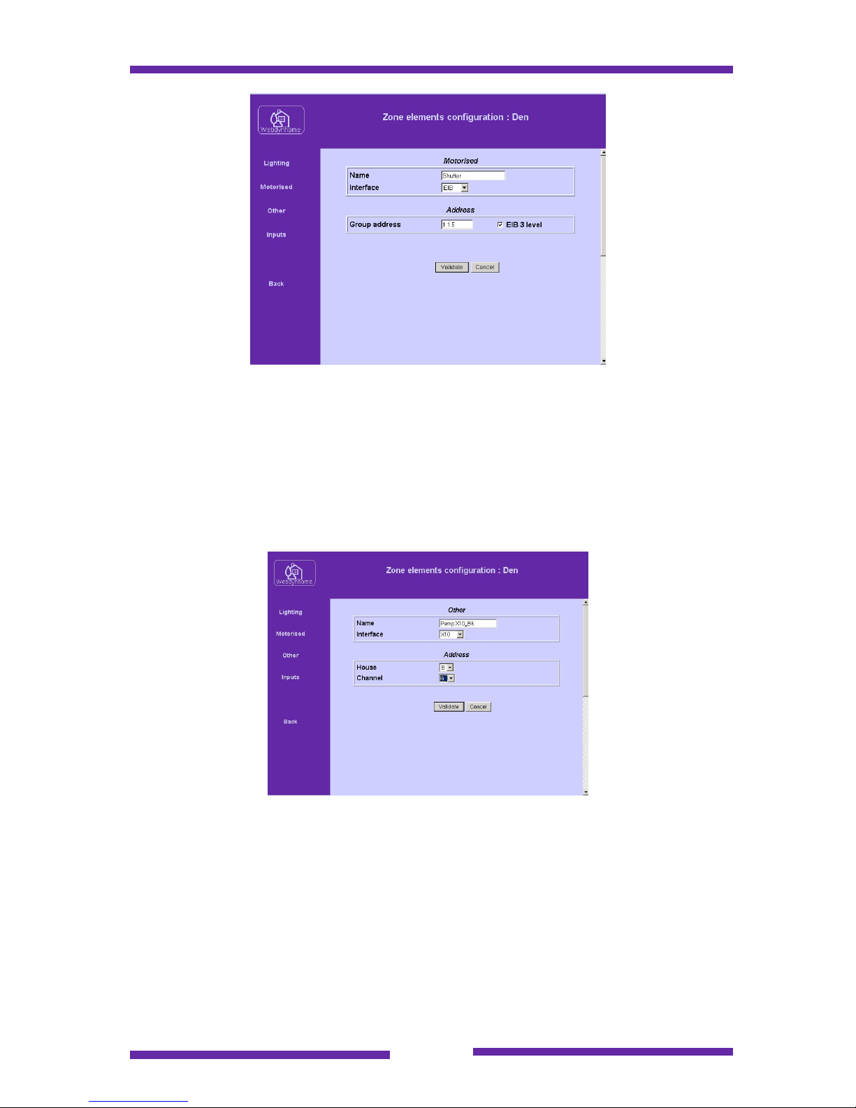
7.3.2 Motorized element configuration ......................................................................... 38
7.3.2.1 X10 motorized elements................................................................................... 38
7.3.2.2 Relay controlled motorized elements............................................................... 39
7.3.2.3 EIB motorized elements ................................................................................... 39
7.3.3 "Other" element configuration ............................................................................. 40
7.3.3.1 X10 other elements........................................................................................... 40
7.3.3.2 Relay other elements ........................................................................................ 41
7.3.3.3 EIB other elements ........................................................................................... 41
7.3.4 Input configuration............................................................................................... 41
7.3.4.1 X10 inputs ........................................................................................................ 42
7.3.4.2 Native digital inputs ......................................................................................... 42
7.3.4.3 EIB inputs......................................................................................................... 42
7.4 Webdynhome scenes............................................................................................................. 43
7.4.1 Scenes configuration ............................................................................................ 43
8 SEQUENCES.................................................................................................... 45
8.1 Creating a sequence .............................................................................................................. 45
8.1.1.1 Simple sequence procedure .............................................................................. 48
8.1.1.2 Conditional sequence procedure ...................................................................... 49
9 ADMINISTRATION PROCEDURES ................................................................. 53
9.1 System backup ....................................................................................................................... 53
Page 4

Page 4
9.2 Restore system configuration............................................................................................... 55
9.3 AV database update ............................................................................................................... 56
9.4 Firmware update..................................................................................................................... 57
9.5 Checking the current firmware version ............................................................................... 58
9.6 Maintenance procedures ....................................................................................................... 58
9.6.1 Maintenance procedures prerequisite................................................................... 59
9.6.2 Recover a lost IP network address ....................................................................... 60
9.6.3 Recover a forgotten installers password............................................................... 62
9.6.4 Reset a Webdynhome to its factory defaults ........................................................ 63
10 PERSONALIZATION..................................................................................... 65
10.1 External server (portal) .......................................................................................................... 65
10.2 Server hosted on the Webdynhome ..................................................................................... 65
11 TROUBLE SHOOTING ................................................................................. 66
11.1 Power cut ................................................................................................................................ 66
11.2 Reset........................................................................................................................................ 66
11.3 Network problems .................................................................................................................. 66
11.4 External events....................................................................................................................... 66
12 GLOSSARY................................................................................................... 67
Page 5

Page 5
1 Introduction
Congratulations ! You are now the proud owner of a Webdynhome.
The product will let you control a complete residential installation using the
conviviality of a Web based interface.
It allows :
- the control of X10 power line devices,
- the control and monitoring of EIB devices,
- the control of domestic appliances via dry contact outputs,
- the monitoring of external events via digital inputs,
- the creation and launching of sequences that may include the control of
environmental devices,
- …
You will discover in this document all the exciting possibilities that the Webdynhome
can offer.
The Webdynhome sits neatly at the intersection between three worlds (home
automation, networking and Web). We will cover each of these topics within this
document and please feel free to skip a section with which you are already familiar.
We hope you will have as much pleasure in using the product as we have had in
creating it.
Factory settings :
IP address 192.168.1.12
Subnet mask 255.255.255.0
User login/password user / user
Installer login/password install / install
Page 6

Page 6
1.1 Terminology
In this document you may find several terms that are new or unclear. Please refer to
the glossary found at the end of the document as a source of assistance.
Don't hesitate to use the glossary as it can sometimes save you lots of time.
1.2 Types of information managed
The exact information managed by a particular Webdynhome depends on the
configuration and equipment to which it is connected.
The Webdynhome may be connected to several types of network :
- The data network (Ethernet based LAN), which enables it to communicate
with IT peripherals (PC's, PDA's, tablet PC's …). This interface also allows
the connection to an intranet or even the Internet (e.g. for remote access)
and to other IP connected devices such as IP cameras etc.
- The telephone network (via modem) for remote access.
- The environmental equipment control network (lighting, motors, captors
…). The communication with this network may be via dry contact, PLC
modem (X10), EIB …
Status
The different states of devices connected to the Webdynhome may be displayed
depending on the type of interface used.
Other
Due to continuous technical innovations, the Webdynhome remains a product ever
attentive to market requirements and to future data exchange mechanisms.
1.3 Types of actions
The Webdynhome may be considered as the gateway between the worlds of the
virtual and the real.
The user must be able to choose which actions to perform. These actions may be
launched manually (locally or remotely), or automatically by pre-programmed events.
They can be divided into several categories :
Commands
Executed in real time by a local user or from a distant "client", by using any terminal
capable of displaying a Web page.
Page 7

Page 7
Control and action
Includes the control and status of the physical input and output circuits of the
Webdynhome.
Automated commands and sequences
Allows complete personalization of the commands and sequences to be executed.
Triggered by either an external event or by an internal Webdynhome generated
routine.
Information transfer
Using the standard email mechanism.
1.4 User types
Three types of user may access the Webdynhome :
- users (who control the connected equipment),
- the administrator (who controls the user rights and certain system
parameters),
- the installer (who sets up the system, adds/deletes the connected
equipment definitions and associated sequences).
Each type of user has access to his/her own view of the Webdynhome together with
the associated functionality.
Each user has a specific login ID and password together with certain other user
specific details (language, screen format …).
Page 8

Page 8
2 Document organization
The document has been created as a "step by step" guide in how to install and
configure a Webdynhome as if you have never seen the product before. It may also
be used as a reference guide for administrative tasks that are performed rarely.
It contains the complete list of functions relative to users, the administrator and the
installer.
Certain sections of the document are reserved for experienced or trained
Webdynhome users.
For example, networking knowledge is required for the IP set-up of the
Webdynhome. It is advisable for inexperienced users to call upon the services of an
"expert" before attempting to configure the IP address, otherwise they may cause
problems on the existing network infrastructure.
The interconnection with low voltage (110/220V) electrical equipment must also be
performed by an experienced installer. This documentation can in no way be
considered as a substitute to a competent professional.
Any problem or equipment malfunction arriving as a result directly or indirectly by the
connection of the Webdynhome to other technical equipment by the user, will not be
considered under any circumstances as the responsibility of Webdyn.
Page 9

Page 9
3 The Webdynhome concept
3.1 What is the Webdynhome?
The world of home automation equipment has up until recently been a closed
proprietary one with a rich mixture of diverse proprietary protocols. The Webdynhome
provides a gateway between several of these existing "languages" and the lingua
franca of the modern world the Web.
It provides the link between the virtual and the real world
Protocol :
The IP (Internet Protocol) protocol is the de facto communication standard. It is truly
universal and enables data sharing between a truly vast array of different equipment
types.
Language :
The language of the Webdynhome is HTML (Hypertext Markup Language), which is
the language used to develop all of the Web pages found on the World Wide Web. It
is very flexible and allows a wide range of styles both graphical and textual.
In selecting open standard protocols and languages the Webdynhome is able
to exploit any type of terminal that supports a Web browser and in turn the
user is able to control the different devices that are connected to the
Webdynhome.
3.2 The native Web site
The native Web site of the Webdynhome is actually generated "on the fly". The
internal system database is used to create a real-time Web based representation of
the different devices connected to the system. This "view" of the system is therefore
always up to date and shows the real configuration of the Webdynhome.
There are in effect two different Web sites that may be visualized, the administration
site (viewed when logged on as either "install" or "admin") and the user site,
accessed when logged on at the "user" level.
3.3 Control
The different devices connected to the Webdynhome will probably use many different
protocols and/or physical interconnects.
IP
There is a small but growing list of devices that may be controlled directly on an IP
network (Web cameras, video projectors ..). The Webdynhome may also be used to
control these devices (typically using HTTP) and in this case may be regarded as an
Page 10

Page 10
aggregation device where a common user interface may be given to different network
devices.
Dry contact inputs and outputs
One of the simplest and most efficient ways to control equipment is using dry contact
inputs and outputs. The Webdynhome contains 6 inputs and 2 outputs that may be
connected to a wide range of devices (push buttons, switches, thermostats, relays,
alarm detectors ….).
X10
Using the previously described interconnects it is possible to monitor and control
various specific types of equipment. A perfect example is power line technology
where in using a suitable power line modem (X10) it is possible to interface the
Webdynhome to a wide range of inputs and outputs. X10 supports a large catalogue
of on/off, dimmer and motor control modules that use the 110/220V wiring as the
control channel.
EIB
EIB (Electrical Installation Bus) is a standards based control bus that is supported by
many electrical equipment manufacturers. Webdyn has been working especially
closely with Hager although several other manufacturers modules (Siemens, Merten,
Jung) have been successfully connected.
It must be noted that the use and installation or X10 power line or EIB technology
requires a certain specialist knowledge and should be handled by trained personnel.
3.4 Sequences
The sequence concept
A sequence is a set of commands that are launched by a predetermined trigger
event.
Each sequence requires the exact definition of two elements : the trigger event and
the action(s) that should be performed once the sequence has been activated.
The principle for defining a sequence is always the same :
Choose a name that is representative (e.g. Lights on)
Choose the manner in which the sequence will be launched (date & time,
detection of an input, by the selection of a zone or available in a user
selectable list )
Define in an ordered manner the list of commands that you wish the
Webdynhome to execute once the sequence is launched. The commands may
be any environment related command.
Embedded sequences
The idea behind embedded sequences is that the user is "protected" from the
complexity of a given sequence of events by automating a complete event behind a
seemingly simple device selection. E.g. In selecting an ambiance it is possible to
descend the several shutters, select a lighting level and select a temperature setting.
Page 11

Page 11
3.5 Alarms
The Webdynhome currently supports a simple alarm function. Based on the detection
of an input (used as a trigger) the system may send you an email and/or open a popup window on a connected user screen.
Page 12

Page 12
4 Safety
4.1 General electrical safety
The Webdynhome conforms to the European CE safety standards, however, certain
basic rules should be observed when installing the product.
The product should be installed in a clean and dry environment.
The power supply of the Webdynhome is designed to be permanently connected to
the mains electricity supply, so a suitable electrical breaker must be installed and
you must be aware of how to use this.
This equipment is connected to the electrical supply and as such all standard
precautions and procedures that apply to electrical equipment also apply to the
Webdynhome.
4.2 Protection against electrical discharges
In case of any defect the Webdynhome must be replaced in its entirety and must not
under any circumstances be opened by other than trained service personnel.
4.3 Additional safety information
Please remember that the Webdynhome may also be used to control equipment that
is located at a remote location. So extra care must be taken before disconnecting or
re-configuring the system.
For the same reason, please make sure that any remote equipment that will be
controlled by the Webdynhome is in a perfect operational state.
Page 13

Page 13
5 Physical installation procedures
As we have already seen the Webdynhome may be connected to several types
of infrastructure.
The connection to certain forms of infrastructure require different types of technical
expertise.
So whoever is about to undertake the installation of the Webdynhome must
have all of the necessary information before proceeding to the next stage of
this document.
Passwords
The Webdynhome must be personalized by assigning specific passwords to system
users. This information must only be known to the appropriate individuals.
IP address
You must know the IP addresses of the IP sub network to which the Webdynhome
will be assigned, the address of the Webdynhome itself and the addresses of any
network terminals or PC's that will be used to access the system.
Email addresses
You must know the email addresses of the users that will receive messages sent by
the Webdynhome.
X10 Power line equipment addresses
Each piece of equipment that forms part of the power line network is assigned an
address. This information is vital in order for the Webdynhome to be able to
communicate with these modules.
EIB equipment addresses
Each piece of equipment that forms part of the EIB installation is assigned a series
of EIB group addresses for specific functions. These addresses were configured
using ETS (EIB Tool Software) and a complete EIB installation map is automatically
produced by this software.
Sequences
After having configured all of the environmental equipment you can start the planning
process concerning the different sequences to be created. It is important to carefully
plan out the sequences before attempting the configuration process.
Page 14
Page 14
5.1 Physical installation
This section deals with the physical characteristics and installation procedures
concerning the Webdynhome product.
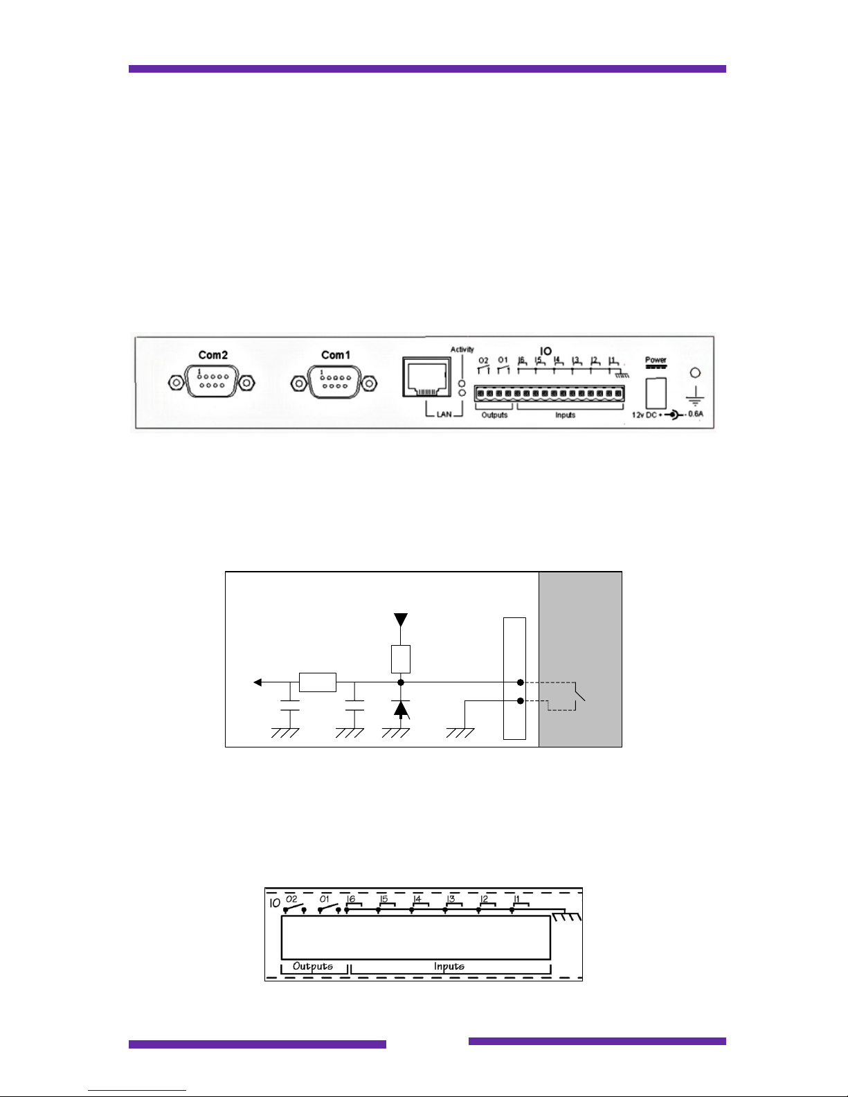
5.1.1 Rear connectors
The rear connectors on the Webdynhome hardware platforms are high quality
industrial grade connectors designed to help the installation engineer. The plug-in
screw connector blocks used for the input/output circuits facilitate ease of wiring
since the connector may be wired without being connected to the system.
Webdynhome rear view
5.1.2 Digital input characteristics:
The digital inputs are common ground 5V TTL circuits.
An input is activated by the presence of a dry contact (short circuit) and may be
represented by the following schema :
+5V
Transil SMBJ5
82C55 input
Webdyncast
input
1K
1K
10nF 100nF
External
interface
Dry contact
The input impedance must not be greater than 150 ohms.
Connector : Weidmüller 3.5mm with cable section 0.5-1.5mm².
5.1.2.1 Webdynhome Input/Output pinouts :
Page 15

Page 15
The connector should be counted from right to left, i.e. Pin 1 is the farthest to the
right.
Pin Signal Description
1 Input 1 Input for dry contact 1
2 GND Chassis ground
3 Input 2 Input for dry contact 2
4 GND Chassis ground
5 Input 3 Input for dry contact 3
6 GND Chassis ground
7 Input 4 Input for dry contact 4
8 GND Chassis ground
9 Input 5 Input for dry contact 5
10 GND Chassis ground
11 Input 6 Input for dry contact 6
12 GND Chassis ground
Pin Signal Description
13 Output 1-1 Output relay contact 1-1
14 Output 1-2 Output relay contact 1-2
15 Output 2-1 Output relay contact 2-1
16 Output 2-2 Output relay contact 2-2
5.1.2.2 Connector specifications
16 point terminal block
Wire section maximum 1.5mm²
Screw head 2.0mm
5.1.2.3 Wiring procedure
1) Bare the wire for a length of 4mm +/-1mm
2) Select the right contact and undo the screw
3) Insert the bare wire into the contact
4) Tighten the associated screw
Page 16
Page 16
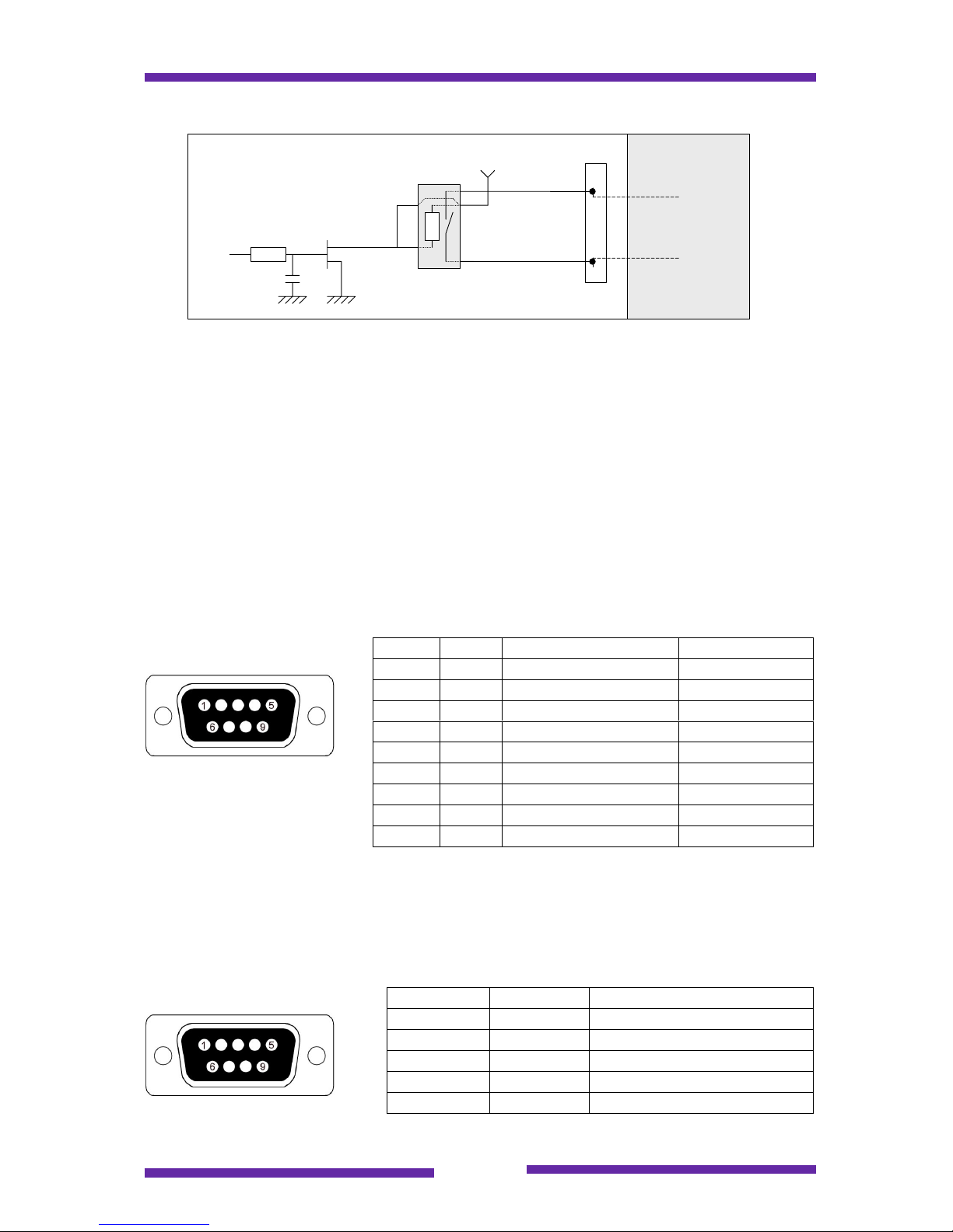
5.1.3 Output characteristics:
7
6
13
1
VCC
9
C
R T
REED relay
82C55 output
Webdyncast
output
External interface
Line in
Line out
The output relay is electromechanical and is open at rest.
It has the following characteristics :
- Voltage : 48Vcc max
- Current : 1A
Connector : Weidmüller 3.5mm with cable section 0.5-1.5mm².
5.1.4 RS232 COM1 Interface
Baud rate : 1200 to 115200 bauds - Connector : SubD 9pts Male.
Pinouts :
5.1.5 RS232 COM2 Interface
Baud rate : 1200 to 115200 bauds - Connector : SubD 9pts Male.
Pinouts :
Pin Signal Description Direction
1 CD Carrier detect Input
2 RX Receive Input
3 TX Transmit Output
4 DTR Data Terminal Ready Output
5 GND Ground
6 DSR Data Set Ready Input
7 RTS Ready To Send Output
8 CTS Clear To Send Input
9 Not connected
Pin Signal Description
2 RX Receive
3 TX Transmit
5 GND Ground
7 RTS Ready To Send
8 CTS Clear To Send
Page 17
Page 17
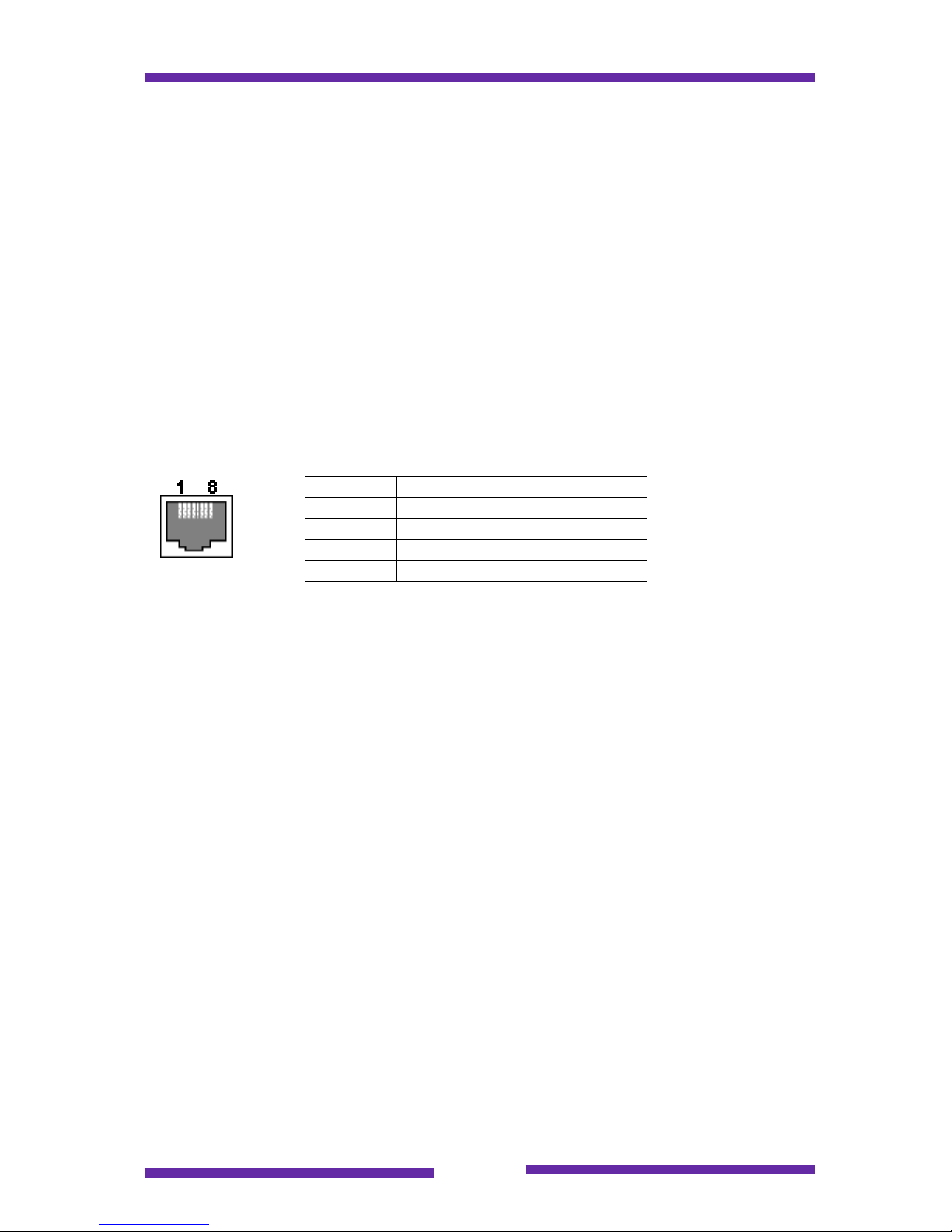
5.1.6 Network Connection
The RJ45 connector located at the rear of the Webdynhome must be connected to
the data network (LAN) within the building. If it is connected to a hub or other network
device the cable required must be straight through. If it is connected directly to
another host (PC etc) then the cable must be a crossed cable.
In order to guarantee the correct operation of the system, the building and network
interconnect cables must be suitable networking grade cables (category 3 or 5).
The Webdynhome Ethernet port is a 10 Mbits/s interface. Most modern networking
components are compatible for both 10/100 Mbits/s and so will function automatically
with the Webdynhome. Should the network be 100 Mbits/s only then you must
connect a 10/100 Mbit switching hub between the network and the Webdynhome.
5.1.6.1 Webdynhome Ethernet connector pinouts
Standard screened RJ45
5.2 Before powering up the system
Connect the rear ground screw of the Webdynhome to a suitable electrical earth
point.
The 12V power supply supplied with the Webdynhome comes with a detachable
international mains voltage plug module. This module must be carefully attached to
the transformer unit BEFORE any connection to the mains power supply.
Connect the power supply to a suitable mains voltage power socket and then plug
the 12V power lead into the Webdynhome.
!!!!Warning
Never attempt to open the power supply block. You run the risk of an electric
shock or creating a fire hazard.
Connect a suitable Ethernet network cable to the LAN socket on the Webdynhome.
Note : If the Webdynhome is connected to a network hub or switch then the cable
must be a straight version. Should you wish to connect your installation PC directly to
the Webdynhome then you must use a crossed cable.
Pin Signal Description
1 TD+ Transmit signal
2 TD - Transmit signal
3 RD+ Receive signal
6 RD - Receive signal
Page 18
Page 18
6 Initial system installation procedures
Upon connection of the power supply the LAN LED should light immediately (if it
starts flashing don't worry, it is indicating LAN traffic activity).
The CPU LED should start flashing after 15 seconds. This indicates that the system
has successfully booted and has now entered the memory load phase. The length of
time taken by the memory load phase will vary based on the system configuration.
If these LED's don't behave as described above after the connection to a suitable
power supply then please contact your supplier.
These next steps will allow you to establish an initial connection with your
Webdynhome from a PC that is equipped with a standard Web browser such as
Internet Explorer™ or Netscape Navigator™.
During the development of the Webdynhome a specific style has been applied to the
user interface dedicated to the installation of the system :
Simple pages containing a minimum of elements
A screen definition of 800x600 (the use of a PDA is restricted to the user
screens)
Large buttons to improve readability
Please verify that your screen definition is adapted to standard Web browsing before
continuing.
6.1 Initial contact with the Webdynhome
In order to connect to the Webdynhome for the first time you need to make sure that
your PC is configured for access to the correct IP subnet.
IP subnet 192.168.1.XX
Network subnet mask 255.255.255.0
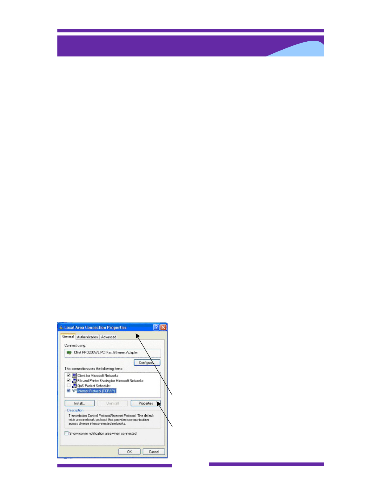
In order to verify whether your PC is configured
correctly, please follow the next steps
Open the Control Panel for your PC and select
the Network Connections option.
After selecting the Local Area Network you will
be presented with a dialog box looking
something like this :
Select the Internet Protocol (TCP/IP) item and
then click on the properties button.
Page 19
Page 19
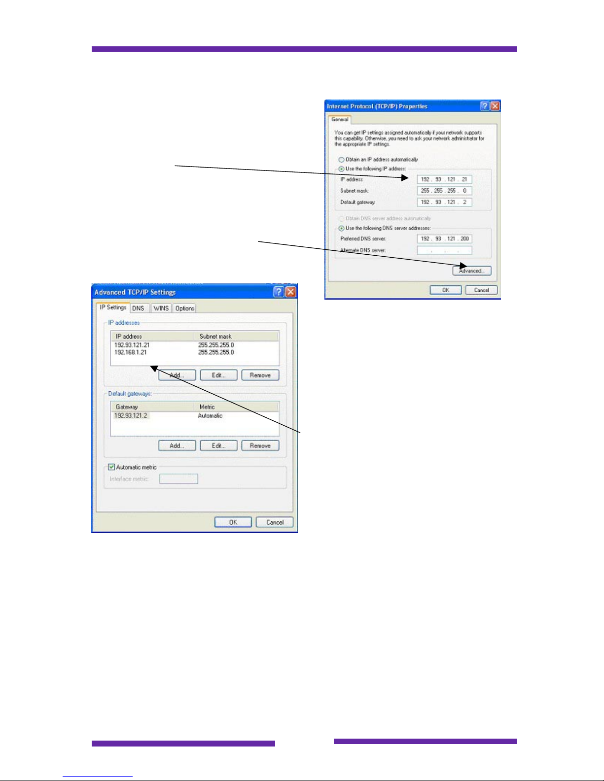
The current IP address configuration for the
PC will be displayed.
This is the PC's primary IP address and must
be on the same subnet as the Webdynhome.
Now click on the Advanced button
This menu displays all of the current IP
addresses configured for the PC. It is
imperative that there is an IP address
configured for the 192.168.1.X subnet
(with the exception of 192.168.1.12 which
is the factory address of the
Webdynhome.
In the example shown here the PC is
configured as host 21 on the following
subnets : 192.93.121 and 192.168.1
Assuming that the previously described network parameters are correct then the PC
will be able to connect to the Webdynhome.
In order to connect to an "out of the box" Webdynhome you need to know the factory
installed IP address :
IP address 192.168.1.12
Network subnet mask 255.255.255.0
Page 20
Page 20
These two elements are all you need to know for a very simple residential network
(where you may leave the factory default settings).
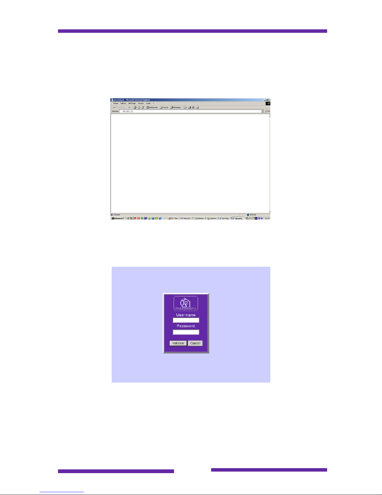
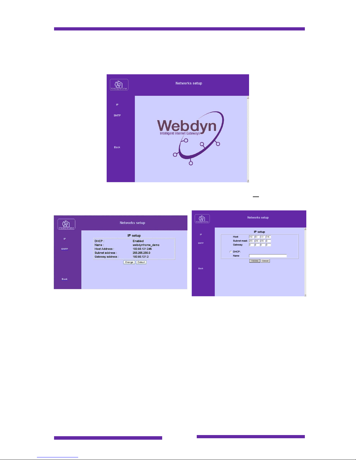
Assuming that your PC is able to connect to the correct network, then all you have to
do next is to enter the address of the Webdynhome in the address field of your Web
browser, i.e. 192.168.1.12 . This is shown in figure 1 below :
As soon as the browser makes contact with the Web server inside the Webdynhome
the welcome screen shown in figure 2 will be displayed. If this screen does not
appear then you could try to test the network connection by using a network
command such as "ping" or contact a networking specialist.
In order to proceed you must identify yourself to the Webdynhome. Three user
accounts are created by default by the factory settings :
A user account (login "user", password "user") which allows
access to the user screens
An administrator account (login "admin", password "admin") that
allows access to certain system parameters
Page 21
Page 21
An installers account (login "install", password "install") that has
total access to all of the system parameters
In order to start the configuration process you must login to the Webdynhome under
the installation account (login "install", password "install").
Please change both the IP address and the password for the "install" user as soon as
possible in order to protect the Webdynhome from unwanted meddling.
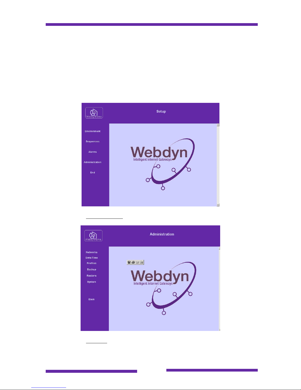
Once logged in to the Webdynhome the following screen will appear :
Click on the link Administration to proceed to the next step :
Click on the link network in order to change the network address of the Webdynhome
:
Page 22
Page 22
6.2 Network Configuration
The current page should be :
If you wish to see or change the current IP parameters then click on IP followed by
the "Change" button and you will be able to modify the appropriate fields :
Warning
During any IP network reconfiguration you must :
Write the new IP address down in a safe place where you are sure you will be
able to find it.
Reconfigure your PC and/or LAN as a consequence of the new address
assigned to the Webdynhome
This chapter describes the procedure necessary to change from the factory assigned
IP address to an address that has been assigned for your specific LAN. Please do
not "invent" an address at random as this could have serious consequences, leave
the process to a qualified expert.
Page 23

Page 23
Three types of information are important for an IP based host :
The host IP address
The subnet mask
The address of the gateway (or router)
The first two points are obligatory, with the third point being optional. All IP addresses
are expressed as a succession of decimal values between 0 and 255 with a decimal
point acting as the separator between fields. Please refer to the network
administrator if required.
Static or dynamic addressing
Static IP addressing means that the IP addresses are configured individually on each
network node (it is simpler and preferable for a small network). The Webdynhome
also supports a method of dynamic IP addressing known as DHCP.
Static mode
(Personalized), the IP address and the subnet mask are entered manually on the
Webdynhome menus. It is important that a qualified networking professional provides
this information.
Dynamic mode
(Option DHCP), the IP address and other parameters are obtained dynamically by
using the DHCP protocol between the Webdynhome and a DHCP server on the
network. This configuration must be performed with the assistance of a network
administrator.
After you have entered the new IP address click on the "Validate" button. You will
now have lost the connection between your Web browser and the Webdynhome.
This is normal. You must change the IP address in the URL dialog box of your
browser to match the new IP address of the Webdynhome, where you will be
presented with the login screen.
6.3 DHCP Configuration
DHCP (Dynamic Host Configuration Protocol) provides a convenient manner for a
network administrator to manage a pool of IP addresses. The Webdynhome supports
DHCP client mode, in other words you are able to dynamically assign an IP address
to the Webdynhome from a DHCP server.
It is the DHCP server that contains a table that lists all network devices under its
control.
On power-up or following a reset, a Webdynhome configured in DHCP mode, sends
a request over the IP network searching for a DHCP server that has the appropriate
address book listing.
If the result is positive, the server returns a complete IP configuration to the
Webdynhome which can then complete its boot process.
Page 24
Page 24
If the result is negative, (no server), at the end of one minute, the Webdynhome
abandons the search and starts up under the last static (manual) IP configuration
recorded.
The way a DHCP server recognizes all the network connected devices is the MAC
address or DHCP name. The Comydyn can be called from the browser with this
name: for example: http://Webdynhome_demo
Note : Some DHCP servers take several minutes to effect the registration process (in
the case of major changes). So please be patient if you are performing many
changes to the network configuration.
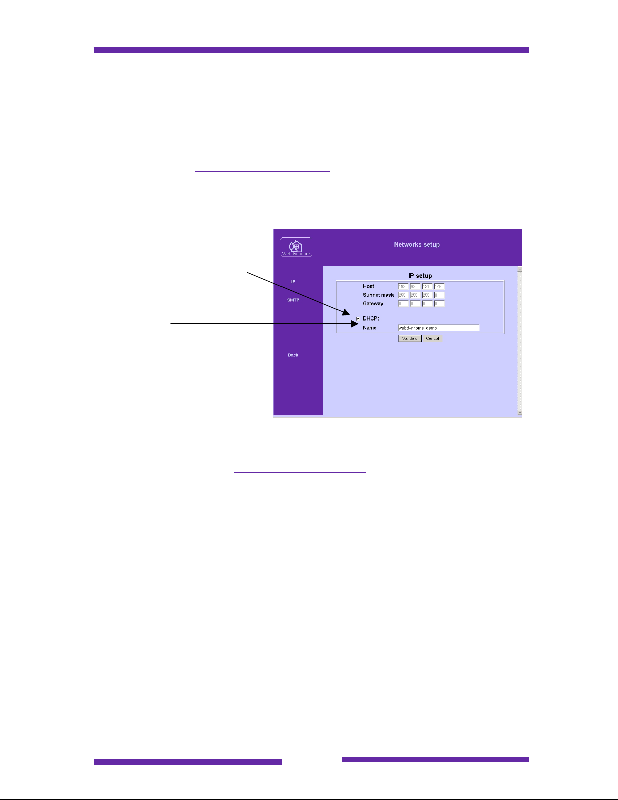
Click on the DHCP select box
and then enter the network host
name that you wish to use in the
future for referring to the
Webdynhome.
Once you have clicked on the validate button then you will need to reconnect to the
Webdynhome using the name that you just entered. Please enter the full string in the
browser address field , e.g. http://webdynhome_demo
You will now be able to refer to the system using its name rather than its IP address.
Page 25
Page 25
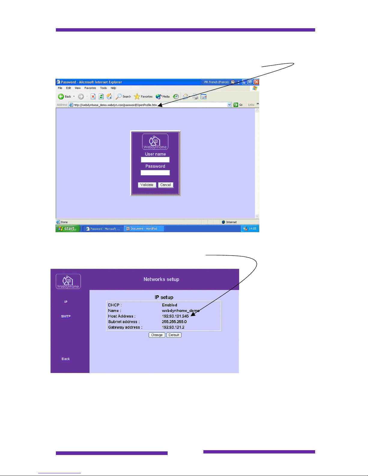
Please note that certain DHCP servers will impose a domain name after the host
name. This can be seen in the example shown below, where we provided the host
name webdynhome_demo and the DHCP server has included the domain
webdyn.com at the end of the name to complete the global address.
If you reconnect to the IP menu, you will be able to see the IP address that has been
supplied to the Webdyncast by the DHCP server.
Note : In order to use the gateway tools that are explained in the Administration
Procedures section, you will need to know the Webdynhome IP address.
Page 26
Page 26
6.4 SMTP (email) configuration
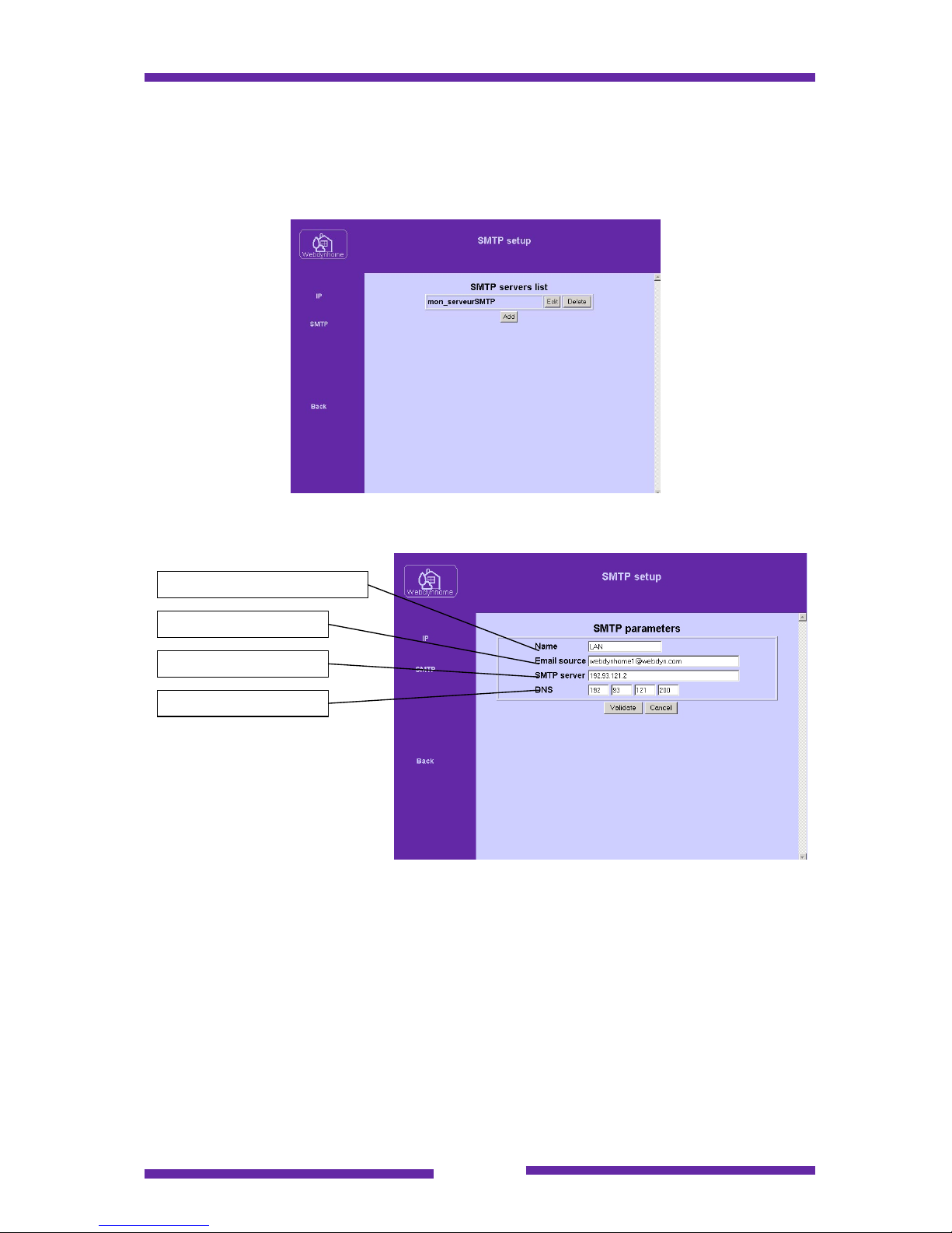
If you wish to see or modify the SMTP (email) parameters of the system, then you
must click on "SMTP" and fill in the appropriate fields :
This information will be supplied by either your network administrator or your ISP.
The reference name will be available in the alarm menu.
The email source address will be indicated in the "From" field if an email is sent by
the Webdynhome. Certain SMTP servers mandate that the source address really
exists others do not. You will need to check this with the network administrator.
The SMTP server address refers to the mail server to which the Webdynhome is
connected.
You must indicate a valid DNS (Domain Name Server) address in IP address format
to enable the SMTP feature of the Webdynhome to function correctly.
Webdynhome reference
Email source address
SMTP server address
DNS address
Page 27
Page 27
6.5 User profile configuration
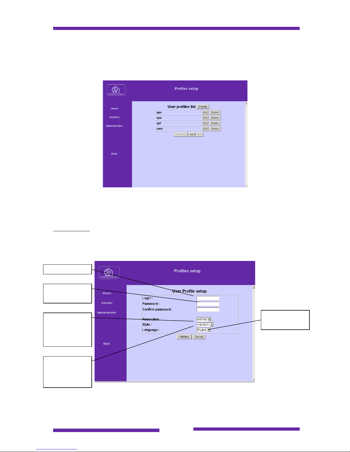
Click on the "Profile" link followed by "Users". The following screen will appear :
Note : The button "Enable/Disable" (see above) is used to enable or disable the login
function for Webdynhome users. If the button reads "Disable" then the login function
is currently enabled and vice versa.
User profile :
Click on "Add" and the following screen appears :
User name
Password
Screen
resolution (PC
or PDA style)
Graphical
display style
(currently
Webdyn only)
User language
Page 28

Page 28
The user parameters are the following :
- login
- password
- screen format (640x480, or 200x200 for PDA's & Pocket PC's),
- language (choose from the select list),
- style (currently WEBDYN only)
You can let users access the Webdynhome in two ways : with a login phase
(standard) or without a login (useful for residential applications). This option is
activated by the "Activate/Deactivate" button (see above).
If the login phase has been deactivated, then anyone connecting to the
Webdynhome IP address will be automatically logged in. This means that if you
subsequently wish to access the installation pages to modify the configuration then it
will be necessary to enter the install address explicitly in the browser address window
:
http://xxx.xxx.xxx.xxx/install
where xxx.xxx.xxx.xxx is replaced by the IP address of your Webdynhome.
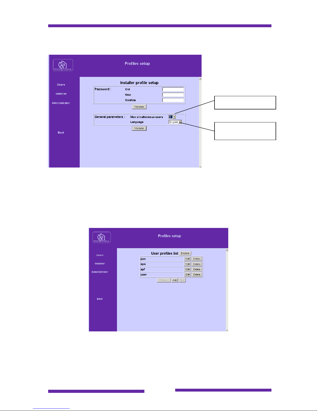
Installer and Administrator profiles :
If you click on "administrator" or "installer", you will be presented with the option to
change the passwords for these users.
This procedure is highly recommended since otherwise the system is practically
unprotected. Some simple rules to help you choose a new password :
Avoid very short words
Avoid a password full of the same characters repeated many times
Avoid family names etc
Avoid special characters like ><« ; , '
To change the password you must first enter the existing password, followed by the
new password repeated twice (for validation). After you have clicked "Validate" the
new password comes into immediate effect and is stored until you decide to change
it. Even after a system reset or power cut, the new password will be
remembered by the Webdynhome so please don't lose it !
Page 29
Page 29
While on the installers screen you may also modify the following parameters :
You may restrict the number of simultaneous system users to between 1 and 10
users. You may also choose the system global default language. This parameter is
defines both the language used for the login screen and the language used to
administer the system.
If you have chosen to let users login, then it is possible for them to login under a
different user language. You may list the system users as shown below :
Max simultaneous users
Installer system
language
Page 30
Page 30
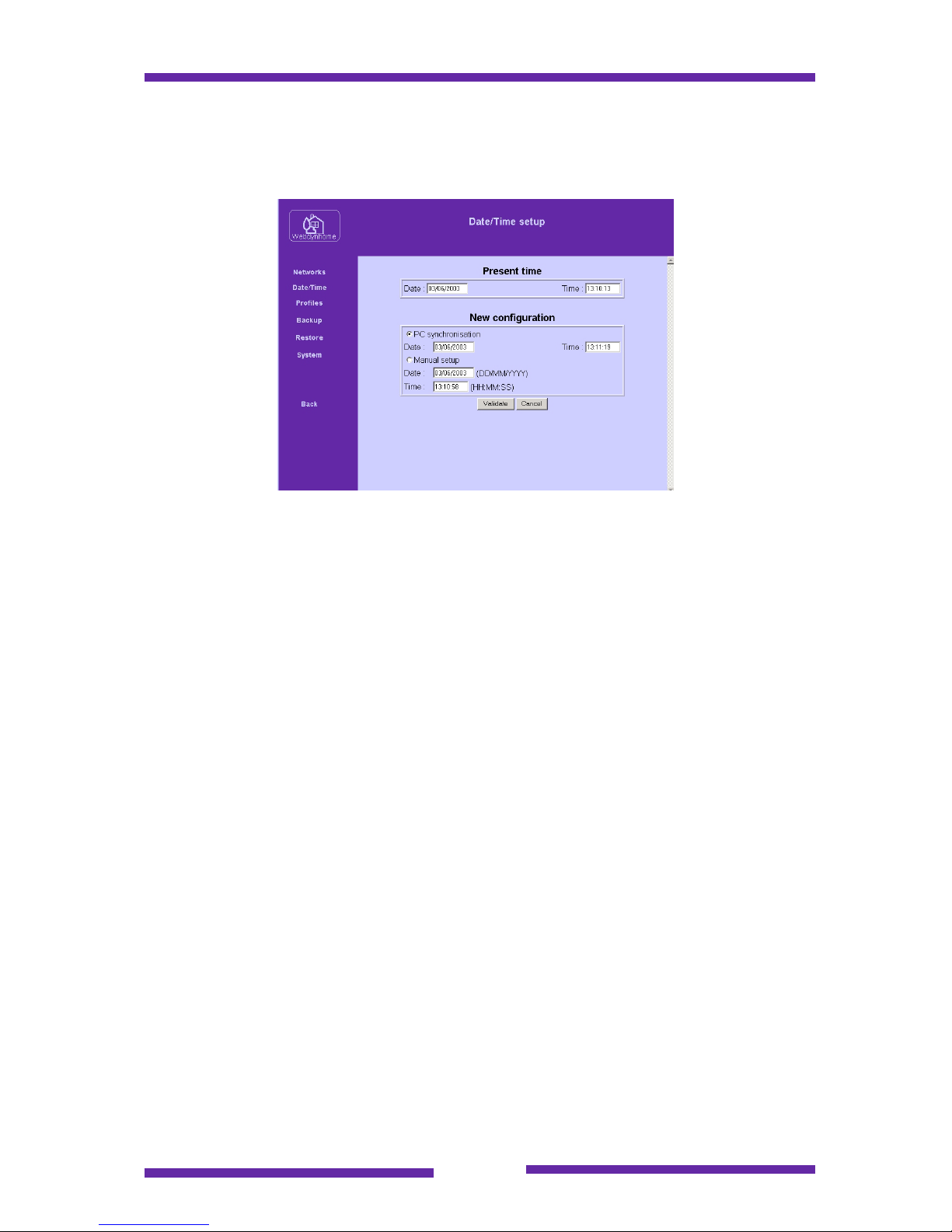
6.6 Setting the system data and time
Click on the link DATE/TIME, the following page appears :
One interesting option is to synchronize the Webdynhome date & time with that of
your PC. All you have to do is to click on the radio button "PC Synchronisation" and
then hit the button "Validate".
Notice
The Webdynhome has an onboard battery to preserve the date & time even in the
event of a power outage. The summer/winter time change is not automatic (since this
is not a universal option) and therefore must be performed manually.
6.7 Alarms Configuration
One of the additional features of the Webdynhome over and above its role as a
control system is the management and notification of alarms.
The current firmware release is able to detect the change in status of any defined
input (dry contact, X10 or EIB) as the trigger event of an alarm condition. Once active
an alarm may be used to send email(s) or activate a Web based screen pop-up to
notify system users of the condition.
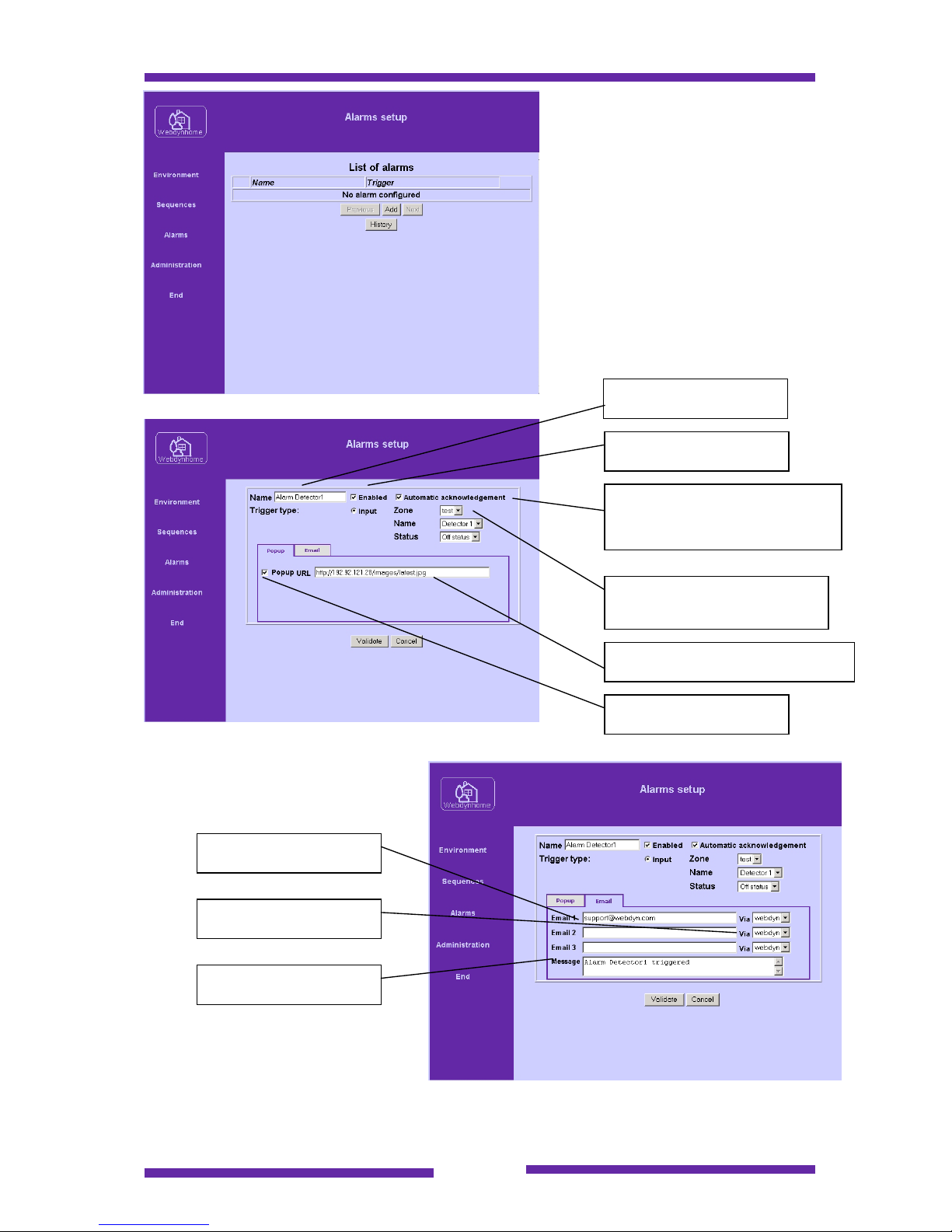
The definition of alarms is as usual a simple menu based solution. The initial alarm
menu is shown below :
Page 31
Page 31
In order to create an alarm you
must click on the Add button.
The different menu options are
shown below :
Alarm name
Enable/disable the alarm
Input definition (Zone, input
name & active state)
Automatic alarm
acknowledgement if the input
state goes inactive
URL for user action (IP camera ..)
Pop-up enable/disable
Email destination user(s)
SMTP server
Alarm email message
Page 32
Page 32
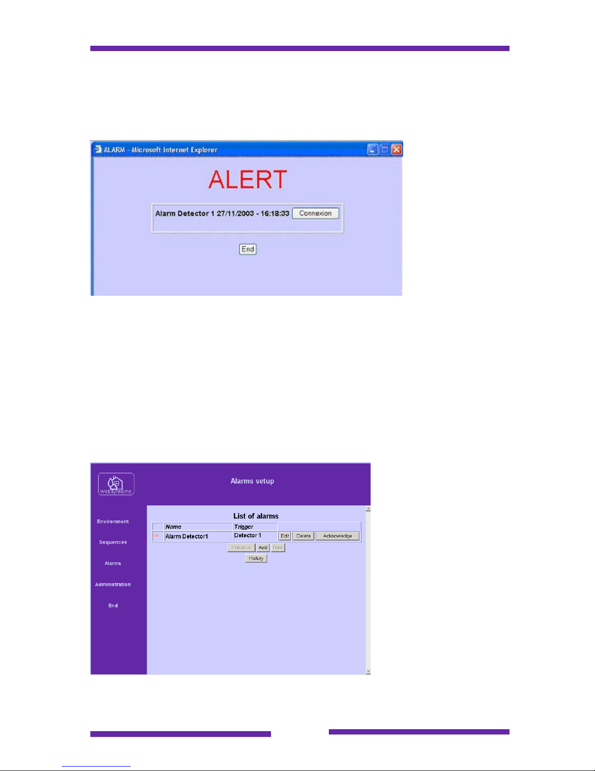
Now that you have defined your alarm(s), what happens when an alarm is triggered?
Let's look at the two possibilities :
a. Screen pop-up
Any connected
Webdynhome
users will receive
the following
screen pop-up.
The optional
Connexion button
will open a new
browser window to
the URL specified
earlier in this
section (the most
common use of
this feature is to connect to a web enabled IP camera (Axis, Panasonic etc…) in
order to be able to visualize what is happening at the location of the alarm.
b. Email notification
Here the email destination user(s) will each receive an email containing the email
message that you specified for the individual alarms.
If we connect to the Webdynhome as the install user we will be able to see whether
the alarm is still active :
If the red arrow is
flashing, this indicates
that the alarm has been
triggered. You may
acknowledge the alarm
by clicking on the
Acknowledge button.
If you had configured the
alarm as being
automatically
acknowledged, then the
alarm will become nontriggered as soon as the
input passes into the
passive state.
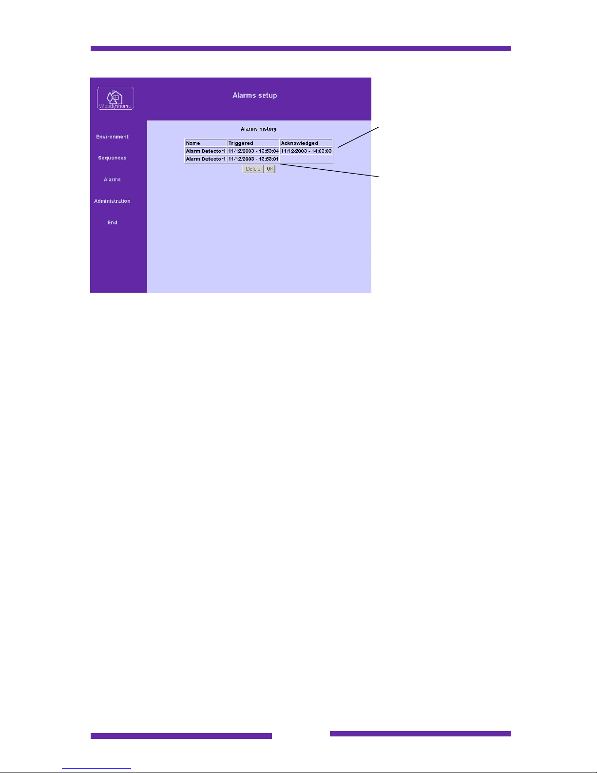
There is a log of recent alarms that may be viewed by clicking on the History button.
Page 33
Page 33
Alarm acknowledged by
user.
Alarm deactivated by
input returning to passive
state.
Page 34
Page 34
7 Environment equipment configuration
We are now going to start the real configuration of the Webdynhome.
You must login to the system as the user "install" either via the login screen or via the
specific URL http://www.xxx.xxx.xxx.xxx/install where xxx.xxx.xxx.xxx represents the
IP address of your Webdynhome.
7.1 Configuration overview
Each device or equipment that is to be controlled by the Webdynhome must be
configured on the system. Once configured, all of the menus relating to the control of
the equipment will be automatically generated for you.
7.2 Environment control
The Webdynhome has been designed to control a wide range of environment style
devices including but not limited to: lighting, motorised elements, inputs, switches,
relays etc. Let's look at the procedures necessary to configure the Webdynhome
relative to your environment.
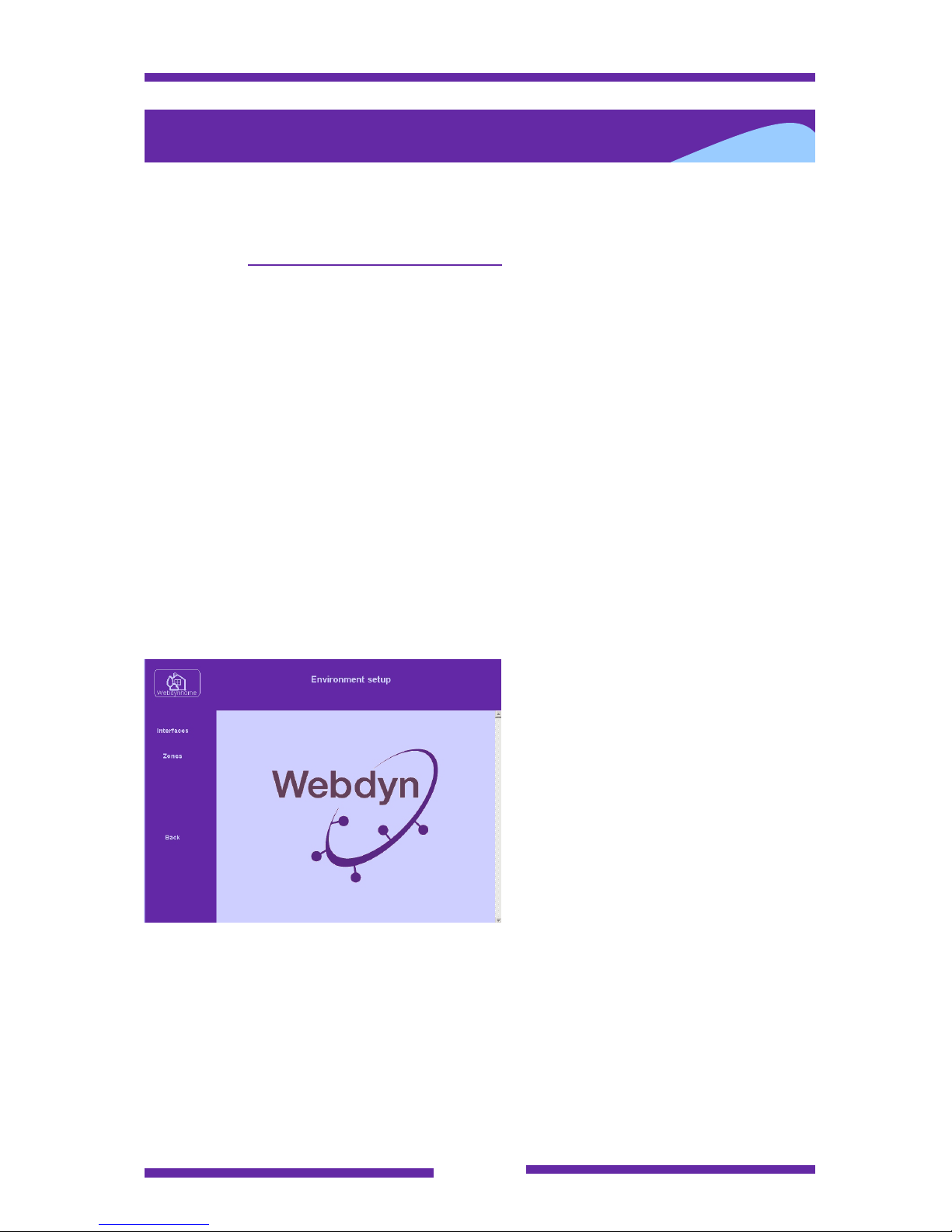
Click on the Environment link and the following menu appears :
The menu Interfaces is used to
assign a generic environmental
device protocol to a specific
Webdynhome port.
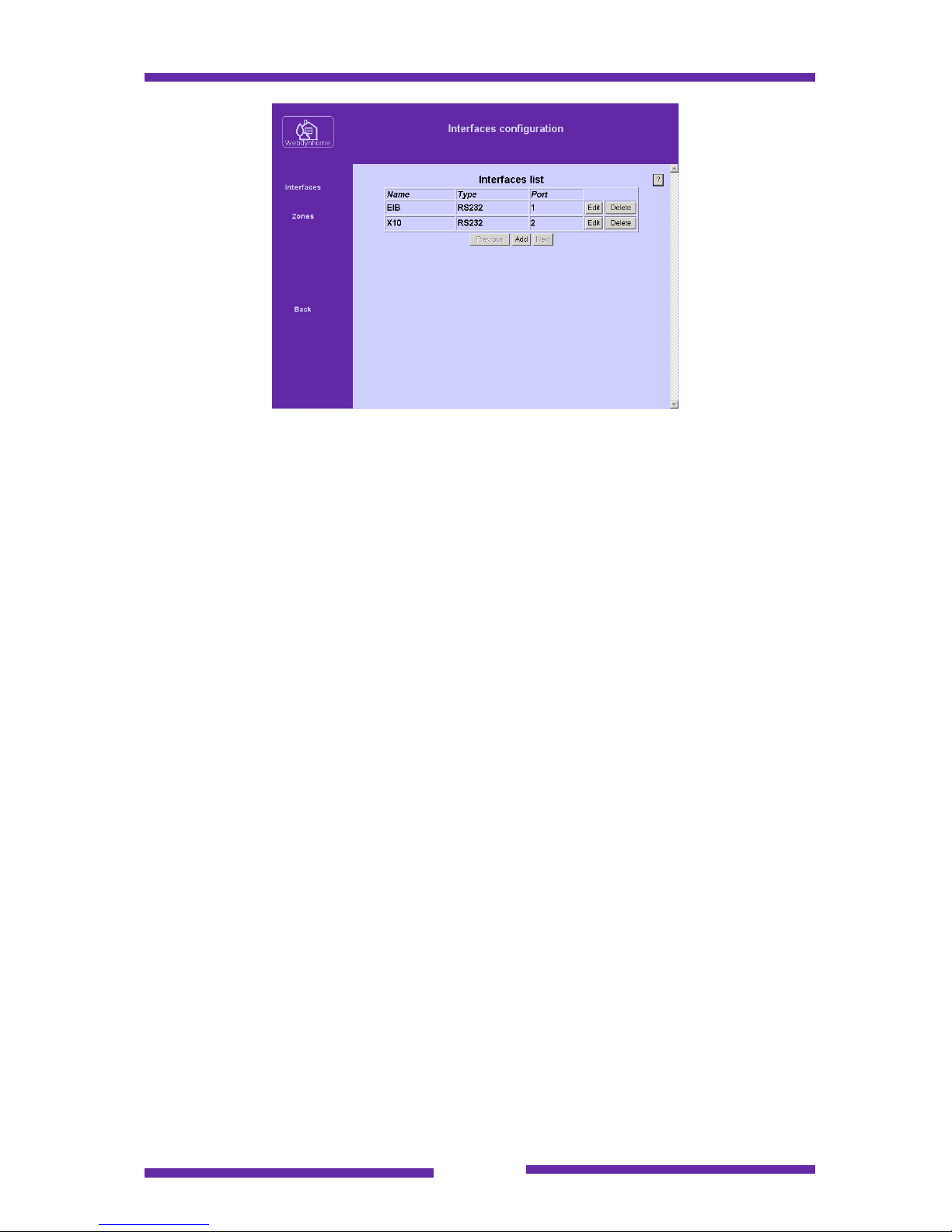
You must specify a unique interface
name : Maximum 10 characters
There are currently 2 different
interface types to choose from, where
the "type" is used to select the
physical interface (RS232) and the
"port" is used to define the precise
port number.
The "interface" selection specifies the exact device that must be connected to the
Webdynhome.
Page 35
Page 35
The currently available interface types are listed above :
EIB : This is an interface driver that assigns a Webdynhome RS232 port to the EIB
(European Interface Bus). In order to perform the physical connection you must
procure a suitable EIB modem. The model currently tested comes from Hager and is
a TH001 with a BCU2.0
X10 : X10 is a widely used power line protocol for which there are many low cost
control modules. The Webdynhome connects to this interface using a CM11
connected to one of the Webdynhome serial ports.
Important note :
The standard Webdynhome user interface now includes the status of the different
environmental devices (lamps, motorized elements etc). It must however be noted
that the "real status" of a device depends on the type of interface. EIB offers a fully
bi-directional interface and as such the indicated status will always be correct. The
X10 control modules currently supported by the Webdynhome are not bi-directional
and so the status indicated on the Webdynhome user screen will only reflect the last
command sent by the Webdynhome. Any native Webdynhome interfaces (relay
today) are obviously known by the Webdynhome and will always be indicated
correctly.
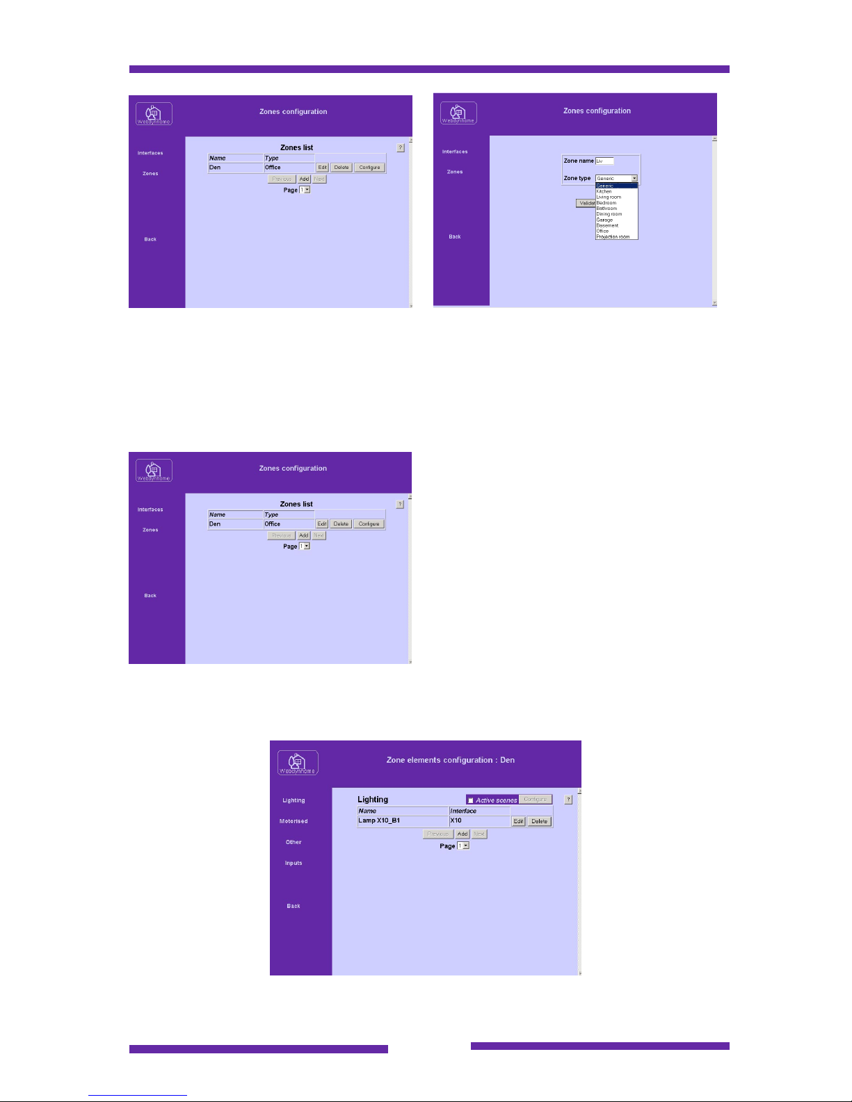
7.3 Environment zones
The environmental equipment controlled by the Webdynhome is grouped into zones.
A zone may be a physical or logical collection of elements.
Page 36
Page 36
Use the Add or Edit button to create or modify a zone.
You must specify a unique zone name : Maximum 5 characters
There are currently 10 different zone types to choose from, where the "type" is used
to select the pictogram that will be used to represent the zone on the user screen.
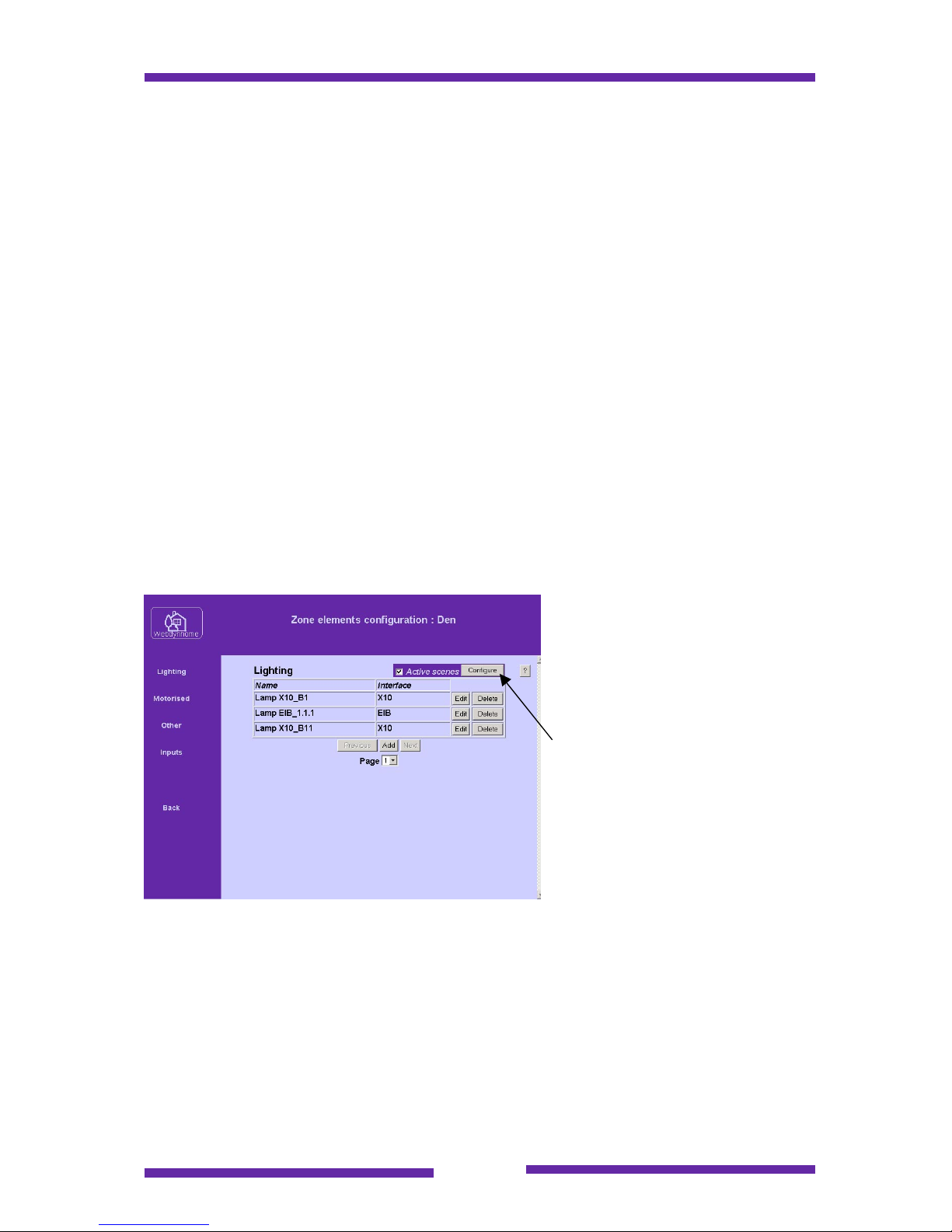
Use the Configure button to add the
different elements to a zone.
The initial element menu is lighting and will appear as shown below :
Page 37
Page 37
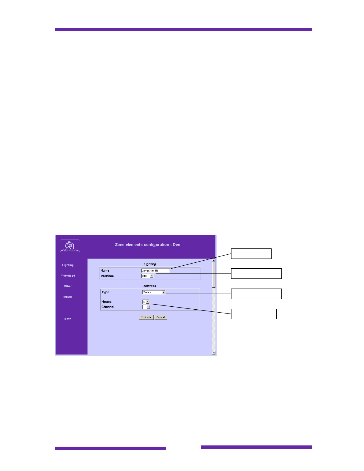
You will notice that the environmental elements have been grouped under 4 different
headings :
Lighting : Different types of lighting controls.
Motorised : Any elements that use electrical motors to control movement.
Other : Any other type of device controlled by the Webdynhome logical or physical
outputs.
Inputs : Used to define the 6 physical inputs connected to the Webdynhome.
As you add the different elements to a zone they become available both within the
zone control menus but also to the control sequences.
7.3.1 Lighting configuration
There are four types of lighting elements currently supported. The different screens
associated to their configuration are illustrated in this section.
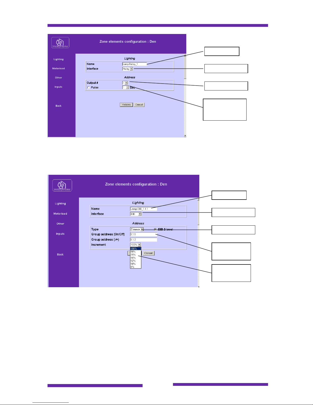
7.3.1.1 X10 lighting
The screen below shows the configuration of an X10 controlled lighting element :
Besides simple on/off modules, there is support for old style X10 dimmer modules
and the newer Leviton modules.
7.3.1.2 Relay controlled lighting
Relay controlled lighting is currently restricted to simple on/off commands, although a
pulse option is available should you wish to switch to a state during a given number
of seconds. A future version will include 0-10V analog outputs.
Light name
Interface type
Module type
X10 address
Page 38
Page 38
7.3.1.3 EIB controlled lighting
EIB lighting supports on/off and dimmer control. You must also specify whether the
EIB addressing is 2 or 3 level.
If you select thee dimmer function then it is also necessary to specify the dimmer
increment as a percentage of 100% e.g. If you choose 25% then each dim plus
command will increase the intensity by 25%.
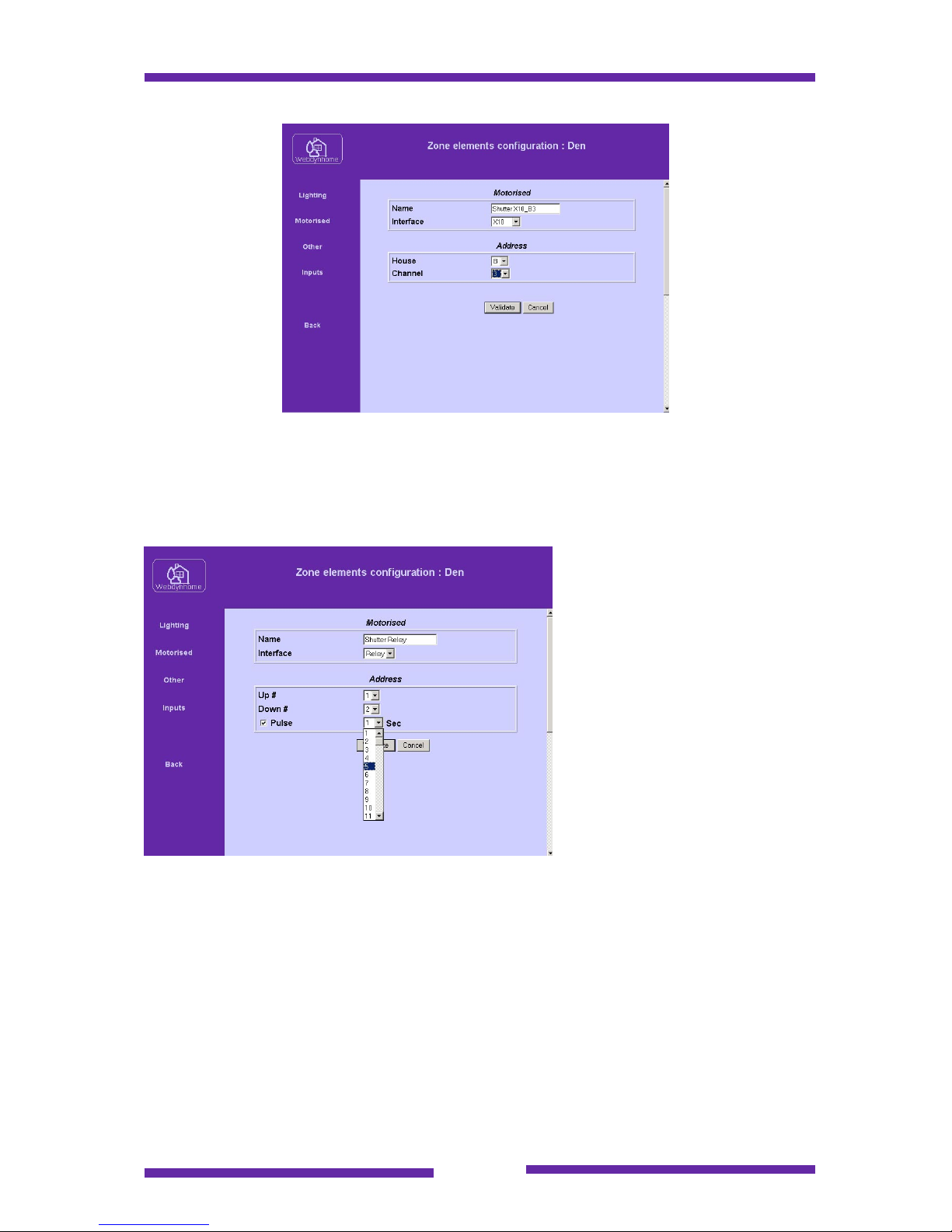
7.3.2 Motorized element configuration
Webdynhome motorized elements are configured in the same manner as the lighting
elements see below.
7.3.2.1 X10 motorized elements
X10 controlled motorized elements are configured as shown below :
Light name
Interface type
Module address
Option pulse
and timing in
seconds
Light name
Interface type
Module type
EIB group
addresses
Dimmer
increment
Page 39
Page 39
7.3.2.2 Relay controlled motorized elements
The 24V relay outputs on the Webdynhome are ideal for controlling motorized
elements such as powered screens or shutters.
You must select one relay for
the up and one for the down
function. It is also possible to
define a pulse period between
1 and 99 seconds so that the
motor will be operated during a
pre-defined period before the
relay is re-opened on the
Webdynhome.
7.3.2.3 EIB motorized elements
EIB motorized elements are configured as shown below :
Page 40
Page 40
7.3.3 "Other" element configuration
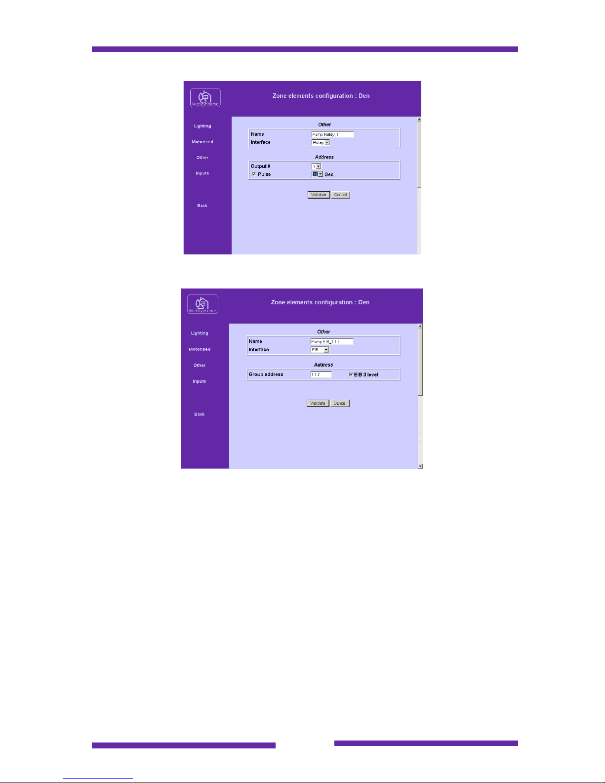
The "Other" equipment menu is used to configure devices that are not lights or
motorized elements and may use all types of media (X10, Relay and EIB) :
7.3.3.1 X10 other elements
Page 41
Page 41
7.3.3.2 Relay other elements
7.3.3.3 EIB other elements
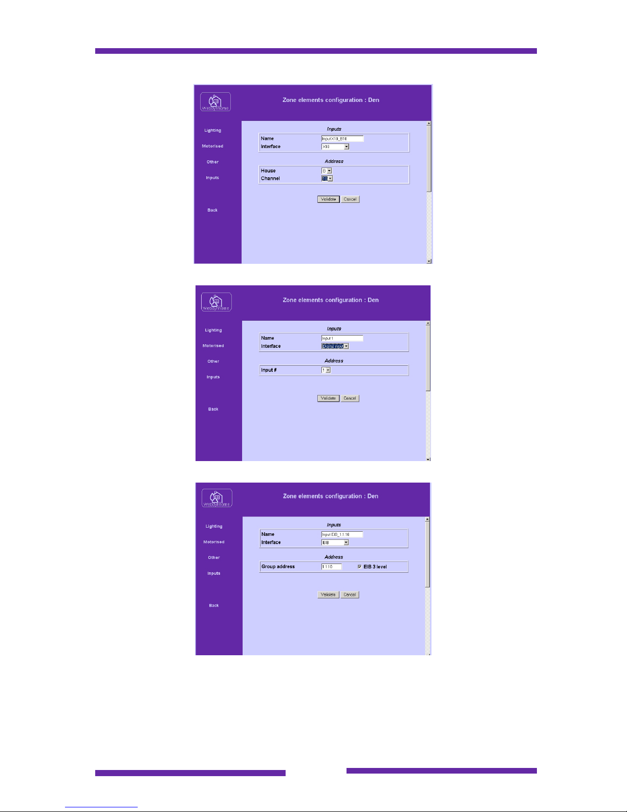
7.3.4 Input configuration
Three types of inputs may be used as control inputs to the Webdynhome. Their
configuration is shown below :
Page 42
Page 42
7.3.4.1 X10 inputs
7.3.4.2 Native digital inputs
7.3.4.3 EIB inputs
Page 43
Page 43
7.4 Webdynhome scenes
Webdynhome scenes offer a manner to group similar elements within a zone in order
to create different ambiances or "mini-sequences". They are applicable for the
standard Webdynhome user interface and are also available via published URLs to
be found in section XXXXX . Using these external URLs it is possible to include
scene control within a custom Web site.
The three defined types of environmental output elements (lighting, motorised and
other) may all be controlled using scenes. Within a zone there may be up to 4 scenes
for each element type, i.e. 4 lighting scenes, 4 motorised scenes and 4 scenes
controlling "other" elements. The idea of scenes is to select each ambiance (or
scene) with a single screen click.
By default scenes are not activated, so each element configured will be accessible
individually on the user screens.
7.4.1 Scenes configuration
If you click the "activate scenes" radio button then you will be able to access the
configuration menus.
Having clicked on the
"Configure" button you will see
the menu below :
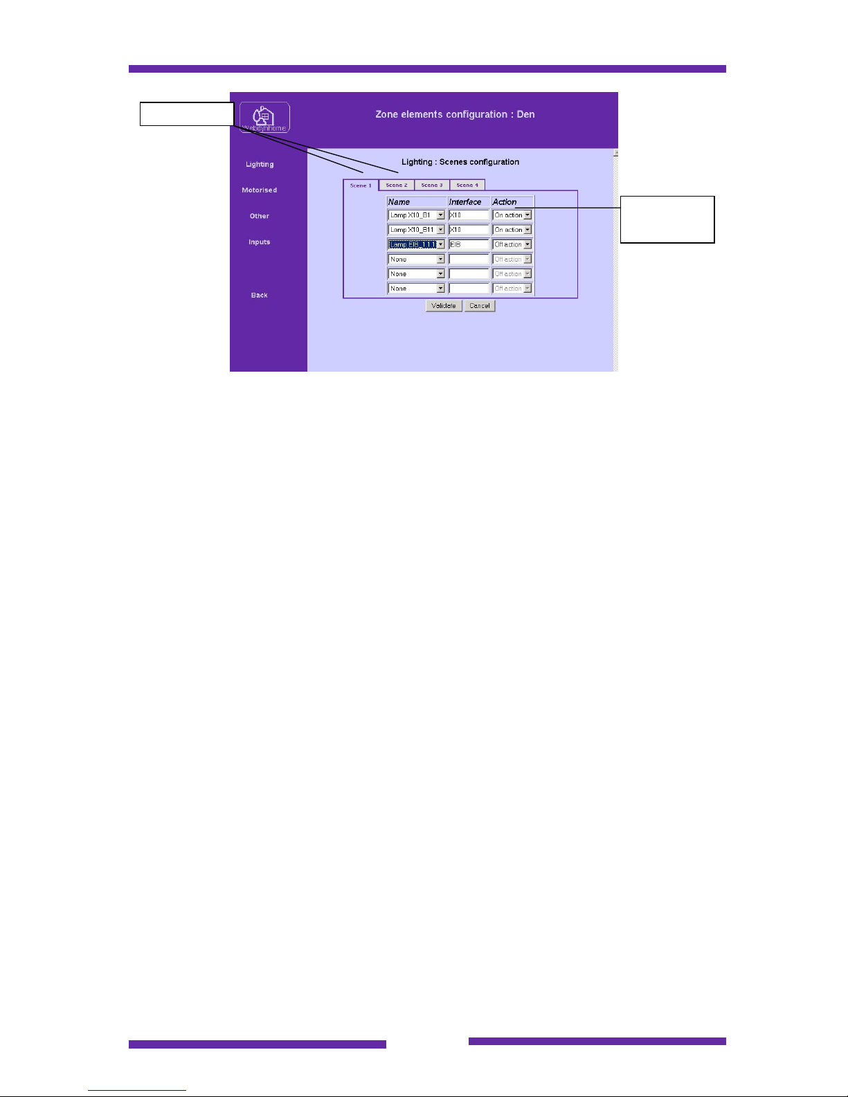
The 4 different scenes are configurable using the associated scene tabs. It is
advisable to create the scenes using the logic (where applicable) that scene 1 offers
the lowest intensity up to scene 4 the highest.
Page 44
Page 44
Please note that if scenes are activated then the individual elements within a zone
are no longer visible at the user menu level, although you may still access them
within sequences.
Scene tabs
Element
selections
Page 45

Page 45
8 Sequences
A sequence is a set of commands that are launched by a predetermined trigger
event. The Webdynhome supports to types of sequence, simple sequences and
conditional sequences.
Simple sequences require the exact definition of two elements : the trigger event and
the action(s) that should be performed once the sequence has been activated.
Conditional sequences require the definition of four elements : the trigger event, the
condition(s) that must be met in order to consider the sequence conditions valid, the
list of actions in the valid case and the list of actions should the condition(s) not be
met.
In order to better understand the Webdynhome sequence mechanisms a few
definitions will help :
The 4 trigger types : Manual (web page click), date/time, physical input, selection of
a zone.
Condition : The result of the comparison between a specified value and a real
status. The currently supported sources are : a defined timeslot and the condition of a
physical input.
Relationship between conditions : Up to four conditions may be linked together
using the Boolean operators AND, OR, XOR. The result is compared to provide the
input for the if and else lists of actions.
If : If the relationship between the conditions is met then this sequence of events will
be executed by the Webdynhome.
Else : If the relationship between the conditions is not met then this sequence of
events will be executed by the Webdynhome.
The principle for defining a sequence is always the same :
Choose a name that is representative (e.g. Sprinkler on)
Choose the manner in which the sequence will be launched (trigger type)
Determine whether the sequence will be conditional or not
Define in an ordered manner the list of commands that you wish the
Webdynhome to execute once the sequence is launched.
8.1 Creating a sequence
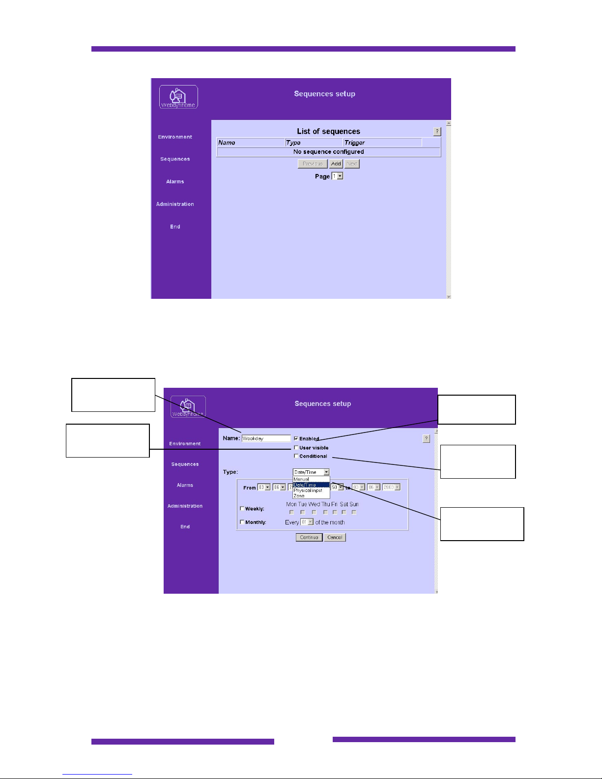
The initial sequence menu will list any existing sequences.
Page 46
Page 46
In order to create a sequence you must click on the Add button :
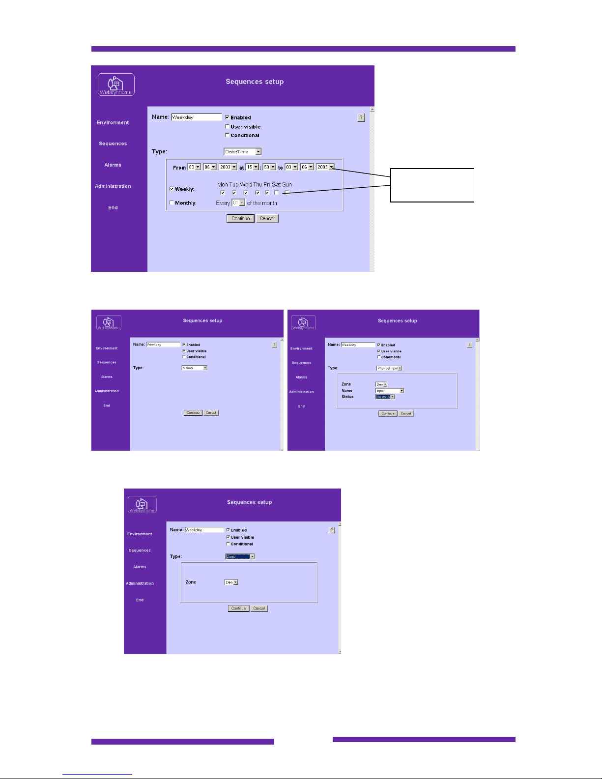
Name your sequence and then choose the trigger type by selecting the type of
sequence:
Depending on the sequence type, a different menu will appear. Each of the screen
options is listed below :
Sequence name
Sequence
initially enabled
Conditional
sequence ?
Visible on the
user screen
Type of
sequence
Page 47
Page 47
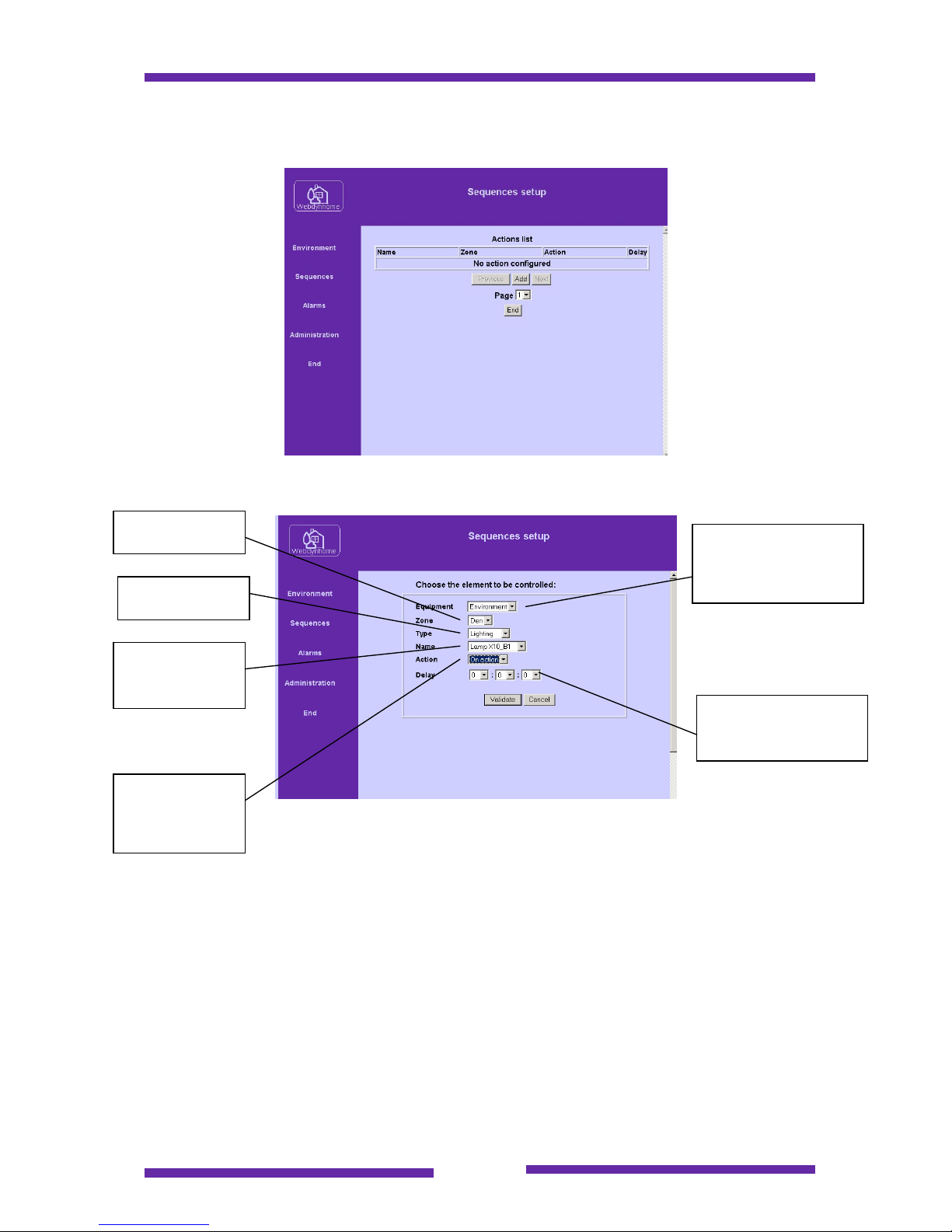
Date/time trigger screen
Manual sequence menu Input trigger menu
Zone selection menu
Having named the sequence and selected the trigger click on "Continue" :
Time slot
selection
Page 48
Page 48
8.1.1.1 Simple sequence procedure
If you did not select the conditional check box then the following screen will appear :
Add the different elements of the sequence :
Note :
All the actions available for all types of equipment are available within a sequence,
even those actions or commands that are not available from the standard user
screens.
Once the required list of actions has been created then the sequence is ready to be
tested.
Choose the
zone
Choose element to be
controlled (currently
environment only)
Equipment
name from
within the list
Specific
command to
execute
Launch delay from T0
where T0 is
immediately
Type of
e
quip
ment
Page 49
Page 49
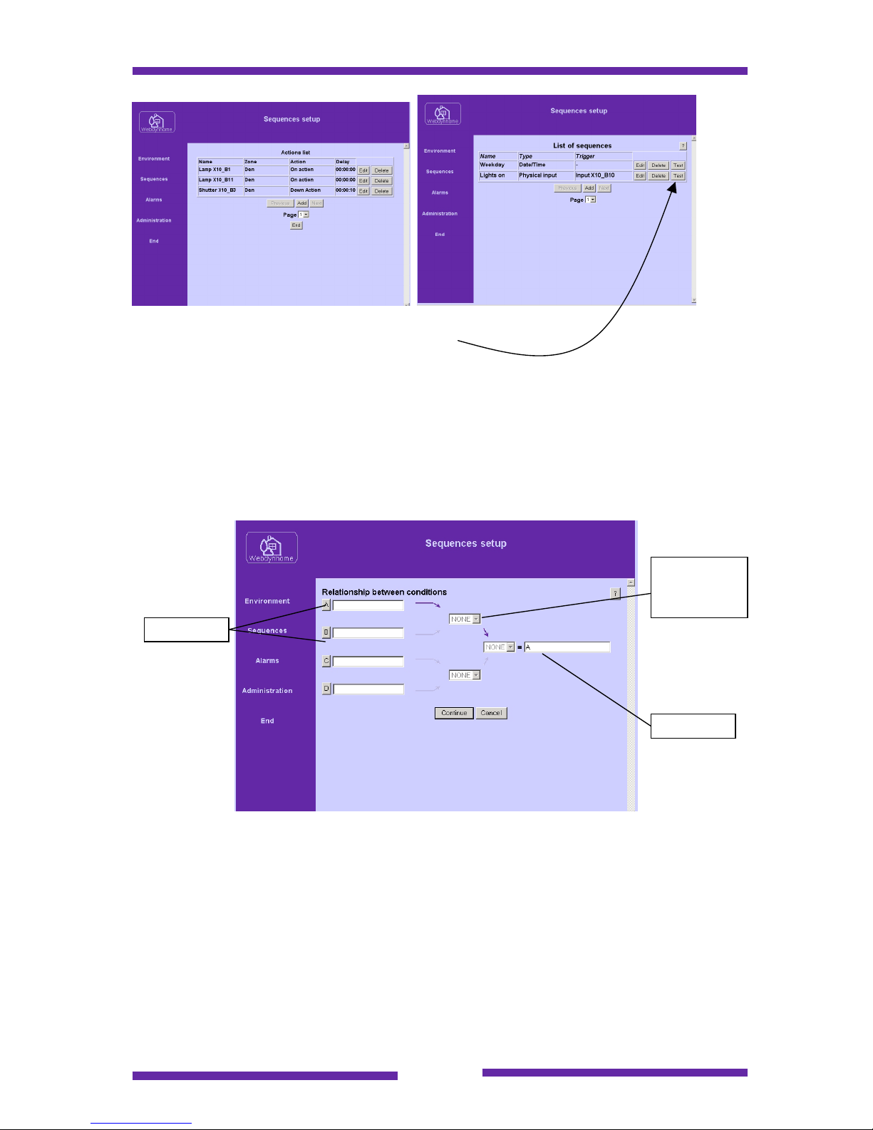
Click on the Test button to run the sequence.
8.1.1.2 Conditional sequence procedure
If you selected the conditional check box then the following screen will appear :
The first thing that you must do is to create the condition(s). Select the A button to
define the first condition. The following screen will appear :
Conditions
Relationship
between
conditions
Result
Page 50
Page 50
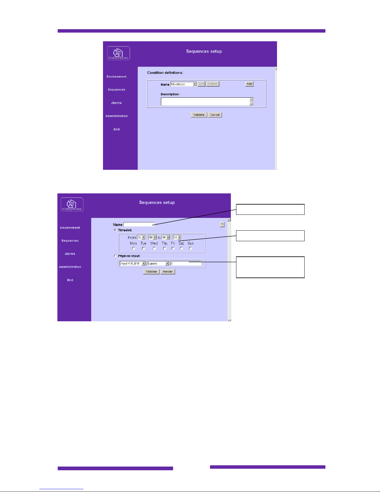
Click on the Add button to create a new condition :
The condition requires a unique name and may be one of two value comparisons :
♦ a valid time slot
♦ the status of a physical input (native digital, EIB or X10)
Once the condition has been created it must be associated to the previous menu by
clicking on the Validate button :
Condition name
Time slot comparison
Physical input state
comparison
Page 51
Page 51
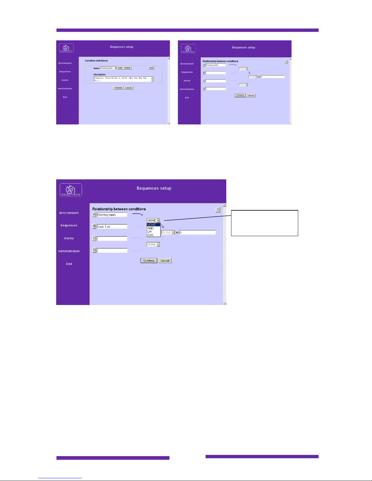
At this stage we now have a single condition that must be met in order to execute the
"if" list of actions.
If we add another condition we will have the opportunity to create a relationship
between the conditions :
You may compare between up to 4 conditions using the operators AND, OR and
XOR.
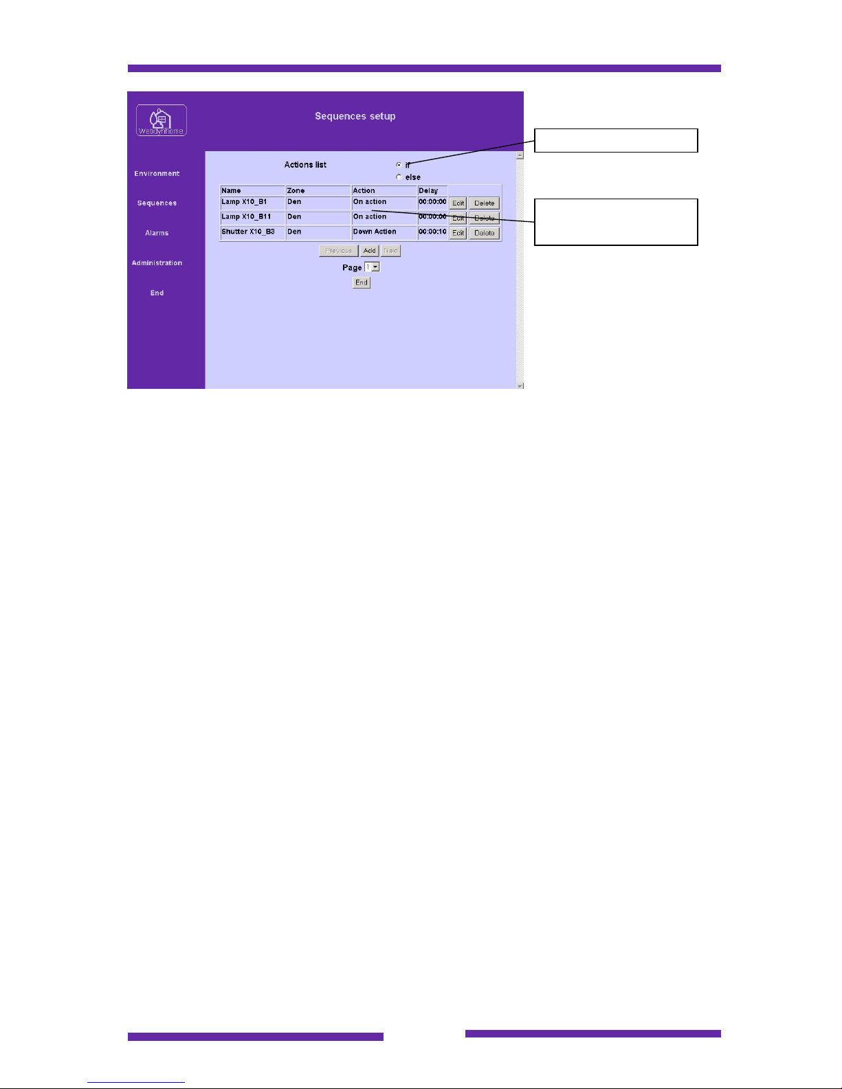
Now that the conditional logic has been created you may define the list of actions for
the if and else cases :
Logical operator
between the
conditions
Page 52
Page 52
Using the procedure described above it is possible to create sophisticated conditional
sequences enabling reliable control "every time" behind single screen buttons or
physical inputs.
Note : The Webdynhome can contain a maximum of 100 sequences with up to 10 if
and 10 else actions.
If and Else check boxes
Add associated action
lists
Page 53
Page 53
9 Administration Procedures
The system administration procedures for the Webdynhome have been grouped into
a single PC based tool. To respect the Webdyn philosophy of no installed client
software, the software tool may be launched directly from the CDROM without being
copied to the PC hard drive (although you may find it practical to copy the tool onto
your PC). The gateway tool is in effect just used to move files to and from the
Webdynhome using simple networked file transfer techniques.
There are seven operations that may be performed using the tool and these have
been grouped into a series of tabs within the application.
Note : The current version of the gateway tools utility is only supported on
Windows 2000 and XP.
9.1 System backup
You are advised to perform a system backup of the Webdynhome once the
configuration has been completed and/or any major changes have been performed.
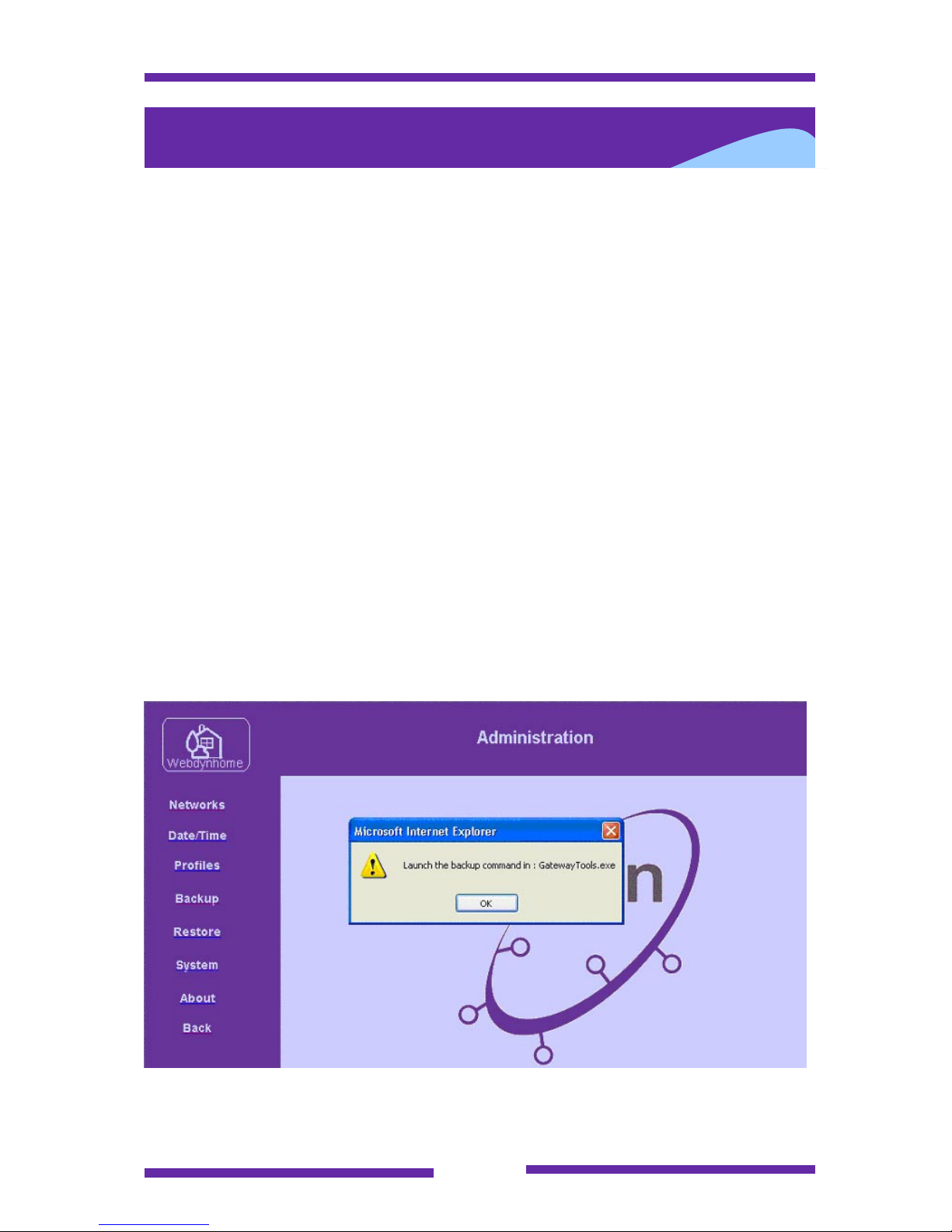
Please note that the system backup procedure must be performed using the
Gateway Tools that are supplied on the Webdynhome CDROM. There is a menu
option in the administration section but this is just used to remind users that they
must launch the gateway utility program.
Page 54
Page 54
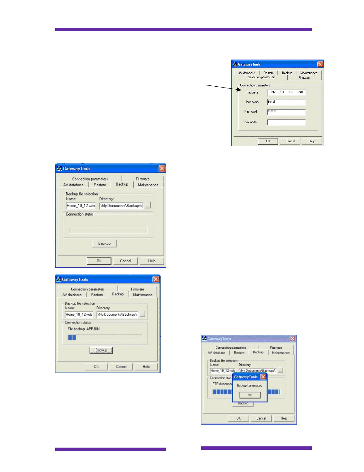
The gateway tools backup procedure is described below :
a. Launch the Gateway Tools application.
b. Make sure that you have entered the
current connection parameters in the
Parameters menu tab (Webdynhome IP
address, user ID "install" and the installers
password)
c. Select the Backup menu tab
d. Enter a backup filename and select the
local PC disk or mapped network drive
(d: -> z:) and directory where you wish to
store the backup image.
Note : You must include the suffix .WDS in the
backup filename
After entering the name and specifying the
directory where the backup is to be stored,
click on the Backup button.
You may follow the progress via the message
window.
At the end of the backup process the following
message will appear.
Page 55
Page 55
9.2 Restore system configuration
If you decide to perform a system restore, then the current installation configuration
will be completely overwritten and replaced by the previously backed up system
image. Be careful …. this even includes the IP address of the Webdynhome.
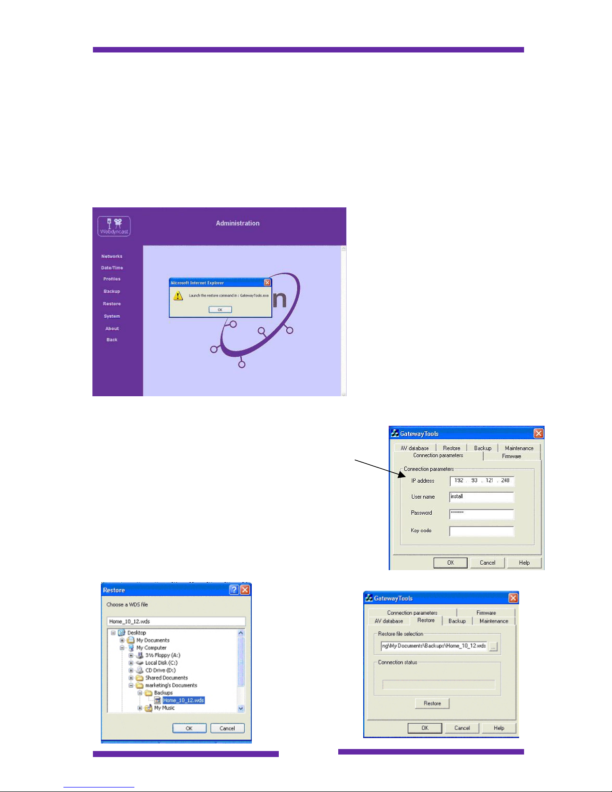
Please note that the system restore procedure must be performed using the Gateway
Tools that are supplied on the Webdynhome CDROM. There is a menu option in the
administration section but this is just used to remind users that they must launch the
gateway tools program.
The gateway tools restore procedure is described below :
a. Launch the Gateway Tools application.
b. Make sure that you have entered the
current connection parameters in the
Parameters menu tab (Webdynhome IP
address, user ID "install" and the installers
password)
c. Select the Restore menu tab
d. Browse the local PC disk or mapped
network drive (d: -> z:) and directory where
your backup image is stored and select the
exact file that you wish to restore.
Page 56
Page 56
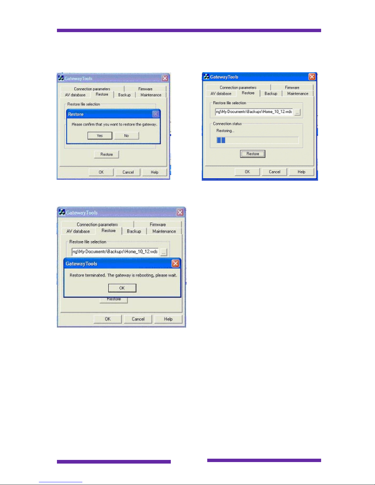
Click on the "Restore" button, you will be asked one last time if you wish to proceed
(remember that the existing system image will be lost forever).
You may follow the progress of the restore process via the message window.
Once the restore process has completed
the Webdynhome is rebooted and will
now offer the exact image (firmware
version, configuration, IP address etc.)
as that of the system on which the
backup was performed.
9.3 AV database update
The Webdyn Gateway Tools are generic for several Webdyn products including the
Webdynhome and the Webdyncast. The AV database tab refers to an administration
procedure that is exclusive to the Webdyncast. Please ignore it.
Page 57
Page 57
9.4 Firmware update
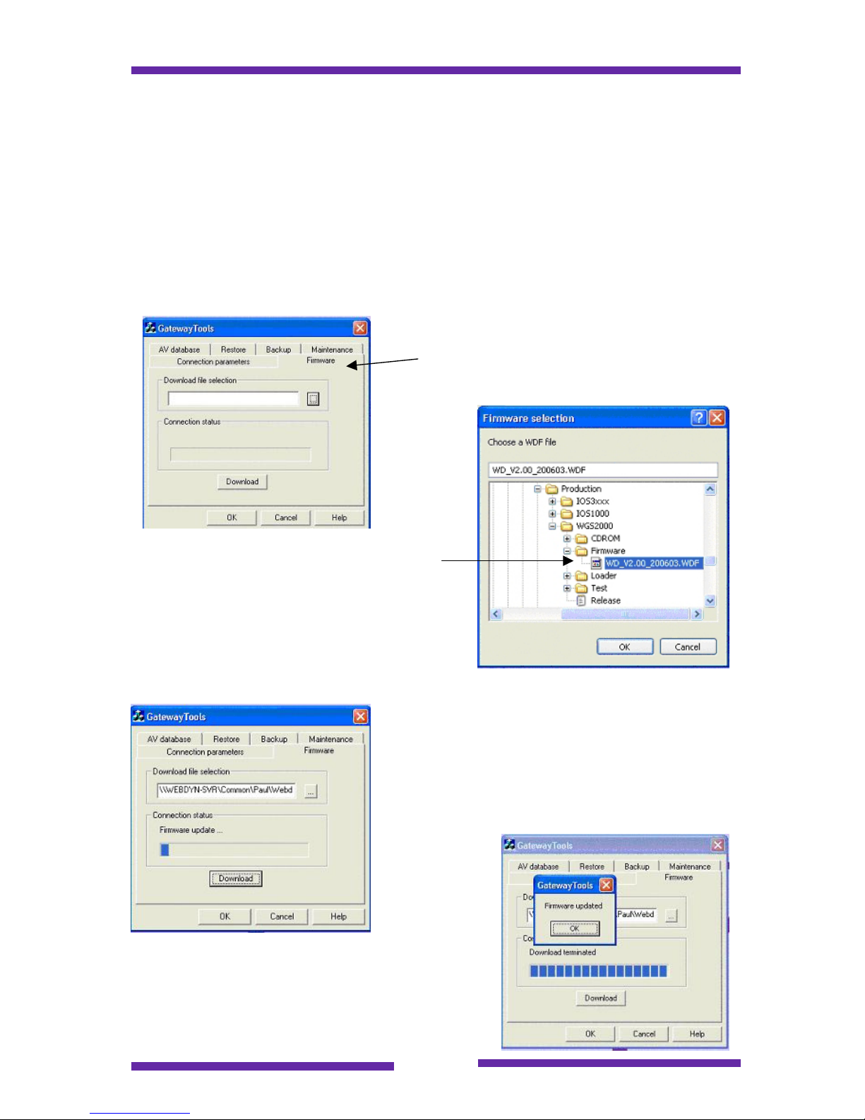
The Webdynhome CDROM contains the Webdyn Gateway Tool which is a small
utility that enables you to perform firmware updates to the Webdynhome.
New versions of firmware will be available from time to time. Please contact your
distributor for more information.
The principle is exactly the same as for the AV database update procedure. You
must enter the IP address of the Webdynhome , the user name "install" together with
its password and then specify the path and filename of the firmware update file.
Select the Firmware tab
Select the firmware image that you wish to
install.
Note1 : All firmware images will have a .WDF
suffix
Note2 : The firmware image must be stored
either on the local PC or on a mapped network
disk (visible as a letter i.e. d: ->z: )
Once you have clicked on the Download button
the process is automatic and you will be able to
monitor its progress using the system messages.
The "Firmware updated" message indicates that
the download process has completed successfully.
Page 58
Page 58
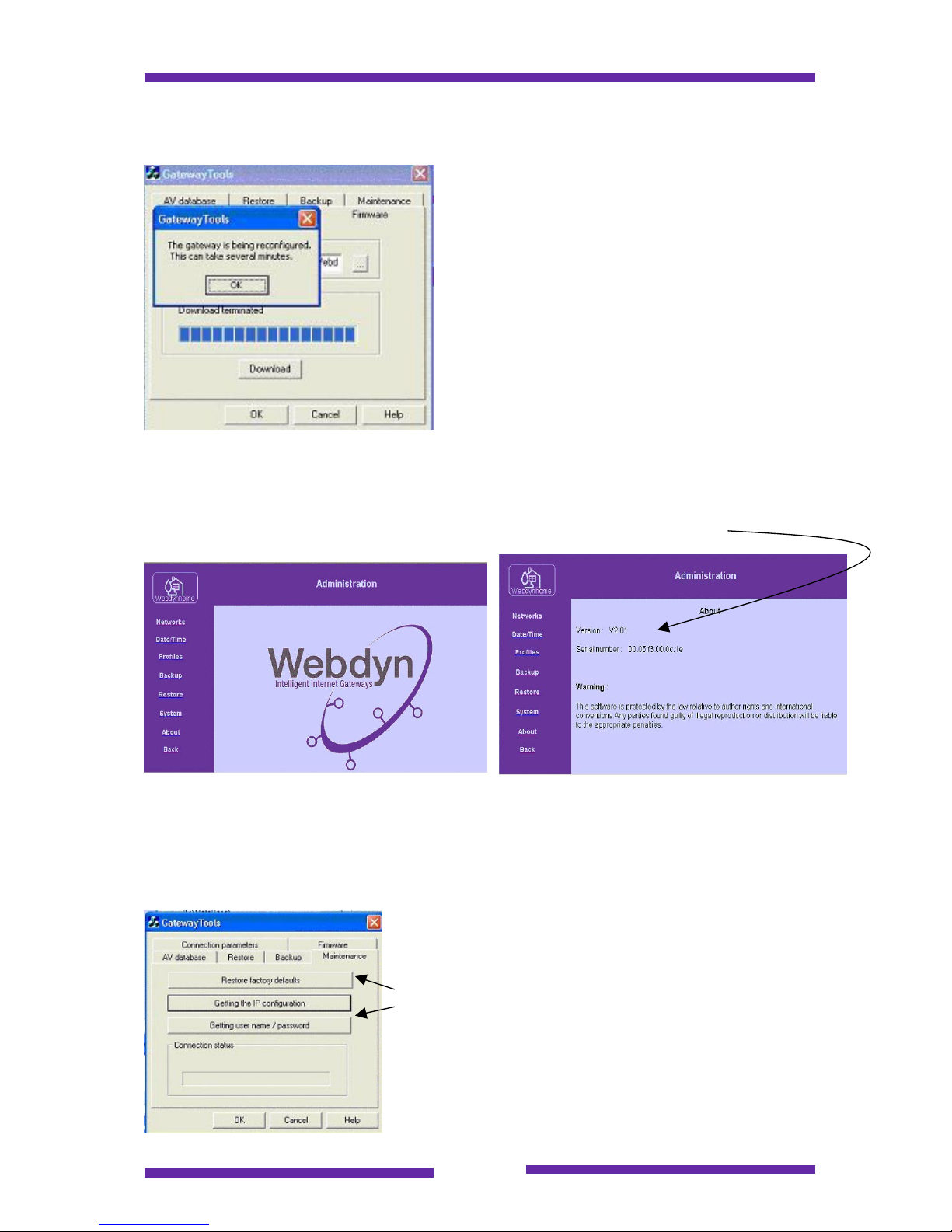
The Webdynhome will now proceed to
reorganize its internal data structures and this
will take about 3-5 minutes. Please be patient
… a coffee would be a good idea.
If you are near the Webdynhome you will be
able to follow its progress via the different
rates of flashing of the CPU LED. Once the
CPU LED is constantly lit then you will be able
to reconnect to the system via a browser.
9.5 Checking the current firmware version
The procedure for checking the current firmware version is very simple. All you need
to do is to go to enter the Administration menu and click on the "About" link.
9.6 Maintenance procedures
In addition to the standard administration procedures that must be performed during
the normal operation of the Webdynhome, there are three specific maintenance
procedures that have been developed to assist installation/maintenance engineers
that are described in this section of the guide.
The maintenance menu options
Page 59
Page 59
9.6.1 Maintenance procedures prerequisite
Before developing the topics, it is important to note that there is a major prerequisite
for each of these procedures. The engineers PC must be configured to be able to
access both the IP network on which the Webdynhome is currently configured as well
as the Webdynhome factory default IP network. This multiple simultaneous IP
network configuration is only supported from Windows 2000 onwards.
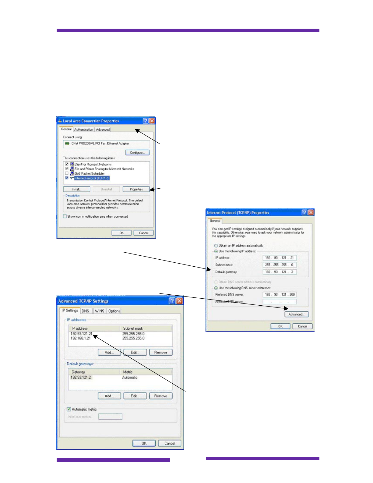
In order to verify whether your PC is configured to enable these operations, please
follow the next steps :
Open the Control Panel for your PC and select the
Network Connections option.
After selecting the Local Area Network you will be
presented with a dialog box looking something like
this :
Select the Internet Protocol (TCP/IP) item and then
click on the properties button.
The current IP address configuration for the
PC will be displayed.
This is the PC's primary IP address and must
be on the same subnet as the Webdynhome.
Now click on the Advanced button
This menu displays all of the current IP
addresses configured for the PC. It is
imperative that there is an IP address
configured for the 192.168.1.X subnet
(with the exception of 192.168.1.12 which
is the factory address of the
Webdynhome.
In the example shown here the PC is
configured as host 21 on the following
subnets : 192.93.121 and 192.168.1
Page 60
Page 60
Assuming that the previously described network parameters are correct then the
following procedures may be performed.
9.6.2 Recover a lost IP network address
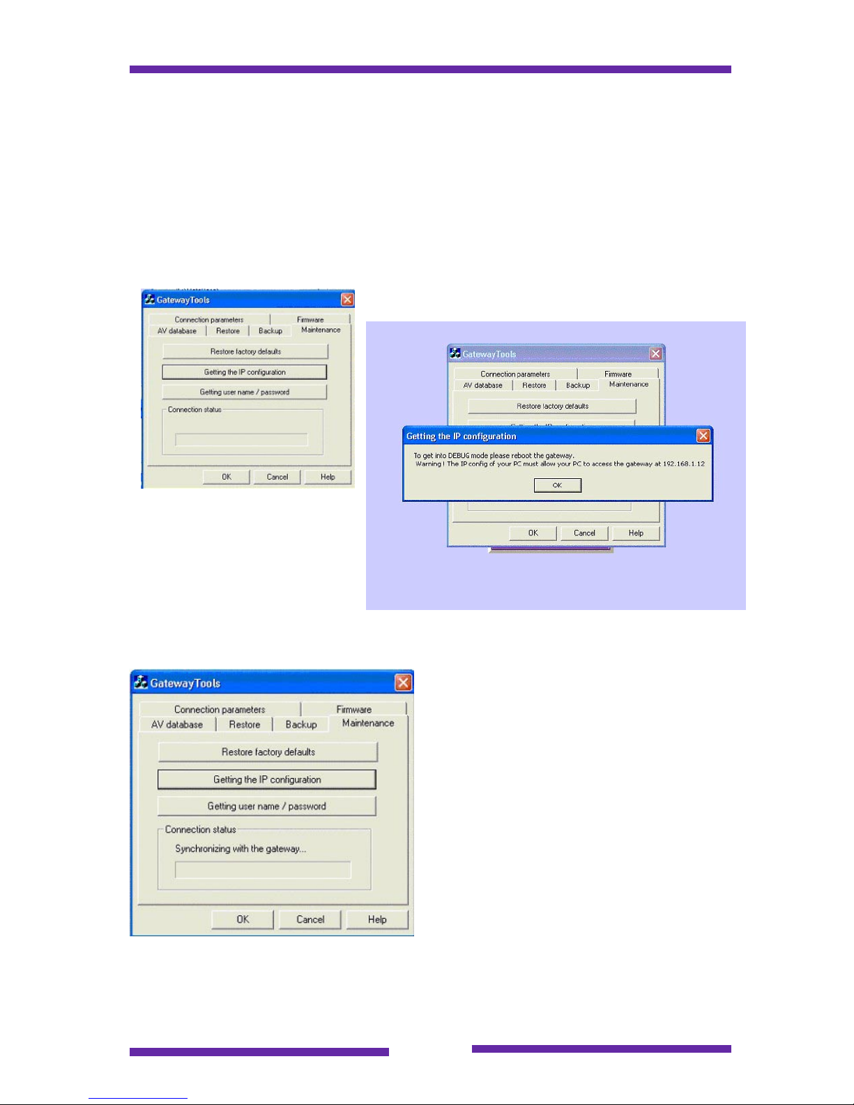
This procedure enables a locally connected PC user to find the currently configured
IP address of a Webdynhome. Make sure that you are sitting at a PC configured as
shown in section 9.6.1 and that you are physically close to the Webdynhome. Launch
the Gateway Tool and click on the Getting the IP configuration button.
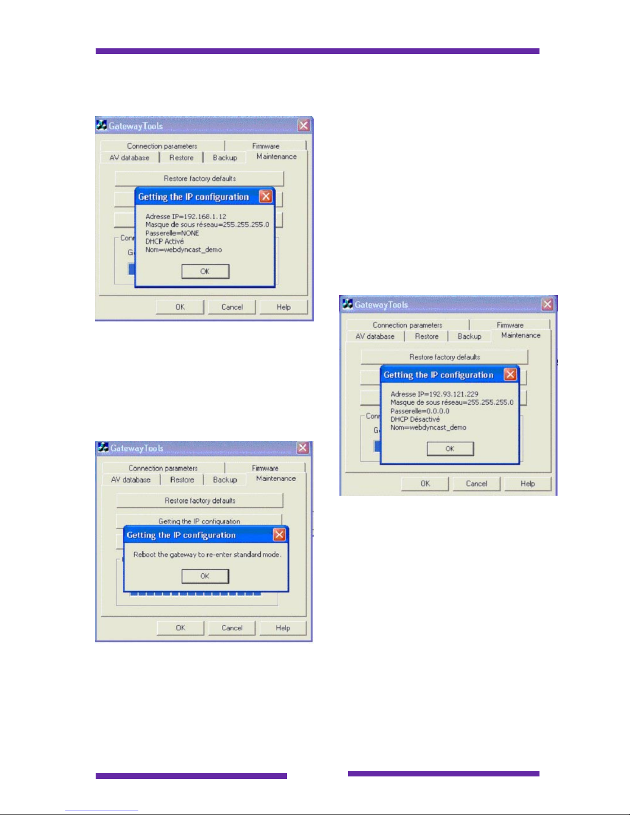
The warning message is asking
you to reboot the Webdynhome
now (you have a time window of
about 1 minute).
Click on the OK button.
You will see in the message window that
the PC is now trying to synchronize with
the gateway.
Page 61
Page 61
The following popup window should now be displayed :
You will notice that in our example that
the gateway has been configured to use
DHCP with the host name
Webdyncast_demo. If you have a DHCP
server on your network then after
rebooting the gateway you should be
able to connect using the name you
supplied. If however, you have no DHCP
server then the gateway will boot using
the last IP address that is indicated in the
popup.
An example of a configuration using a static
IP address is shown here.
Once you have retrieved the IP address
that you were looking for then all that
remains is for you to reboot the gateway
and connect to it using this address.
Page 62
Page 62
9.6.3 Recover a forgotten installers password
Since one of the keys to the security of the Webdynhome is the install users
password then this must be protected at all costs. However, this high level of secrecy
can sometimes result in the loss or failure to remember of the password by the
person who needs it. Without this, no administration procedures are possible on the
Webdynhome.
So Webdyn needed to provide a mechanism whereby the qualified system user could
recover a forgotten password, whilst at the same time protecting this same user
against illicit attempts at retrieving the password.
The solution proposed by Webdyn is the following :
1. The user wishing to recover the install user password sends an email to
[email protected] together with the serial number of the
associated Webdynhome.
2. Webdyn generates a temporary security key code and sends this back
to the requesting user
c. The security key code is only valid during a limited period of time and
so the risk of illicit use is minimized.
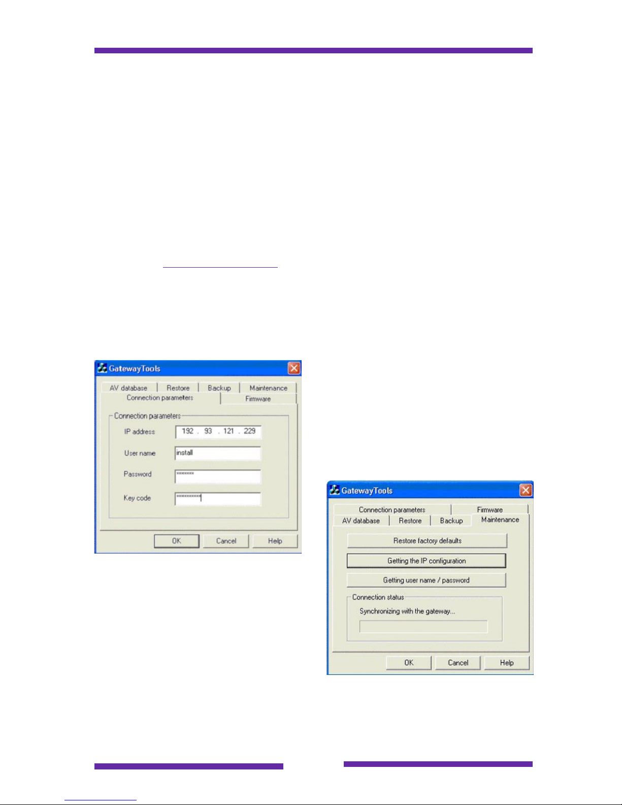
Once the key code has been received it
must be entered in the key code field of
the connection parameters menu tab.
The Getting user name/password button is
hit, followed by the reset of the
Webdynhome.
Page 63
Page 63
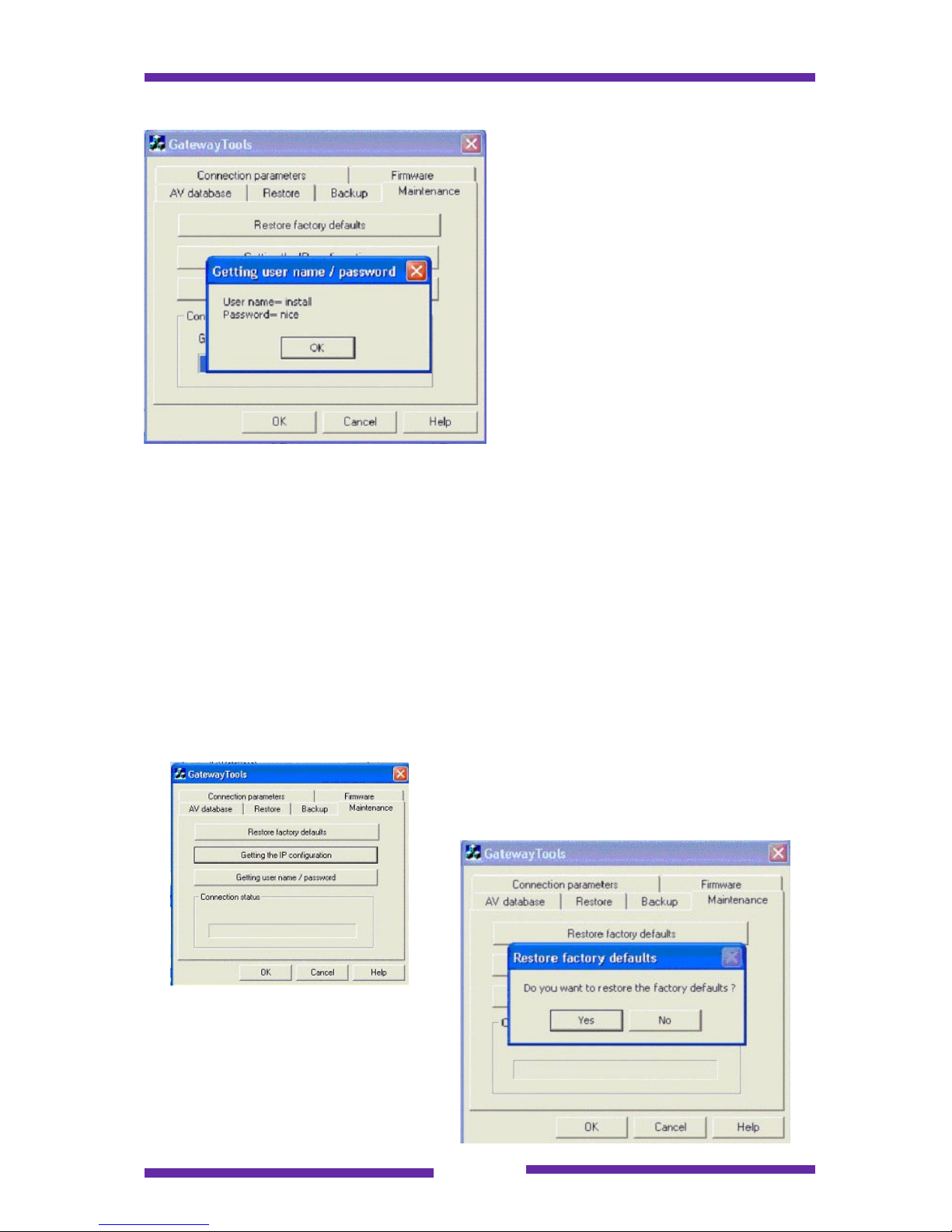
A popup window containing the install
user name and password will be
displayed.
Now you must reboot the
Webdynhome and you are in business
9.6.4 Reset a Webdynhome to its factory defaults
This option will reset the Webdynhome to exactly the same state as when the product
was first delivered, i.e.
IP address 192.168.1.12
Subnet mask 255.255.255.0
User login/password user / user
Installer login/password install / install
The procedure is protected by the install user connection details, which must be
entered in the connection tab of the tool.
Click on the Restore factory defaults tab.
You will get one more warning before
it's too late :
Page 64
Page 64
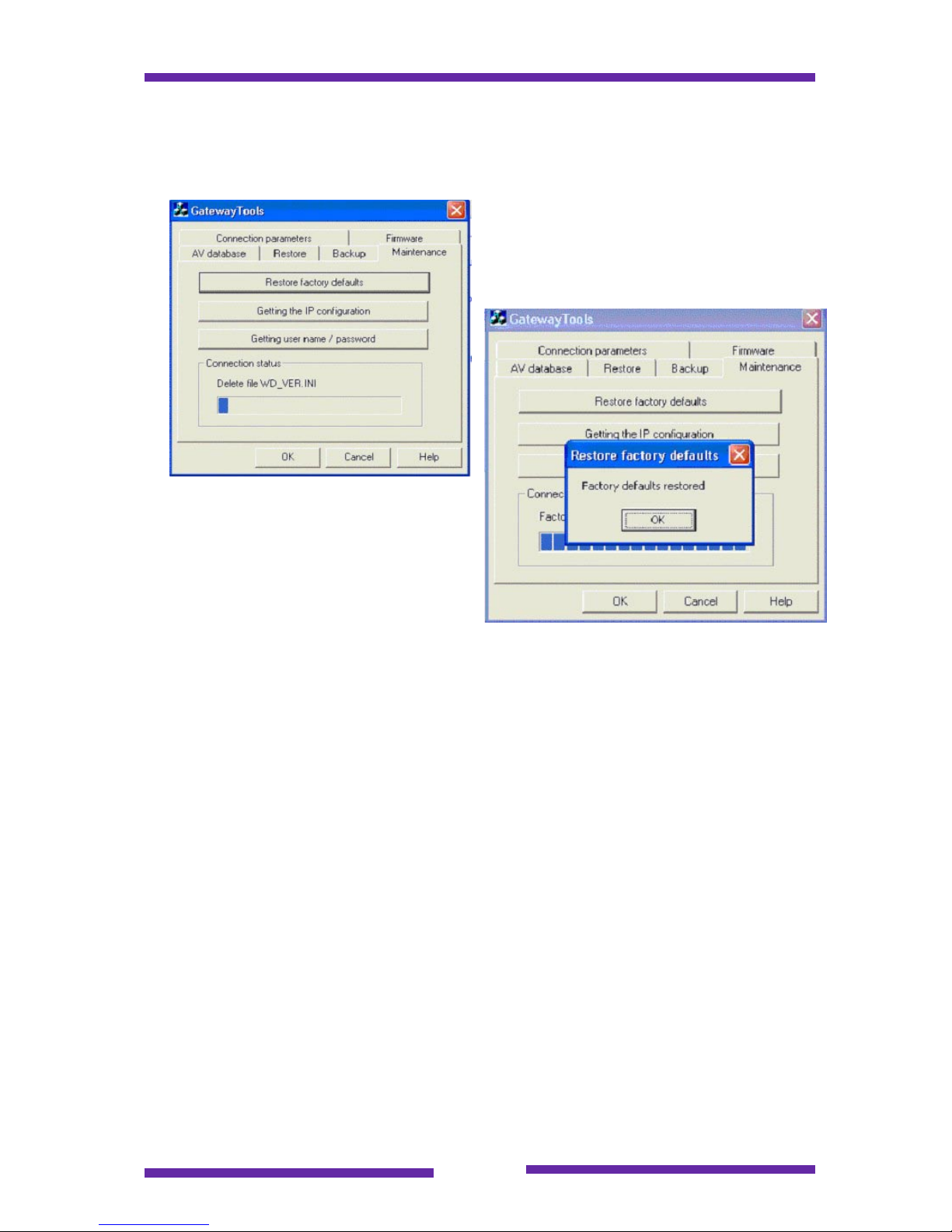
In clicking on the Yes button, you can say goodbye to the existing configuration.
All of the configuration files will be
deleted.
Once you have this message then all that
remains is to reconnect to the
Webdynhome using the factory IP
address of 192.168.1.12.
Page 65

Page 65
10 Personalization
The Webdynhome has been designed from it's inception to be totally customizable
and it is possible to create a fully personalized user interface for system users. The
principal is explained in this section.
10.1 External server (portal)
It is possible to develop a Web application hosted on an independent server that is
used to launch commands and/or sequences that exist on the Webdynhome.
This allows total flexibility to create any kind of user interface that a customer could
desire. The principle is very simple, since the Webdynhome uses HTTP requests to
launch its own actions then all that is necessary is to embed the correct HTTP syntax
behind the portal server pages and redirect the clients request to the Webdynhome.
10.2 Server hosted on the Webdynhome
The Webdynhome has sufficient internal memory to be able to host a simple portal
application without the need to add an external server.
This approach imposes certain restrictions :
The Webdynhome operating system (OS) does not support
dynamic page formats such as asp or php
The OS imposes a DOS style naming convention for all
filenames (i.e. 8 (name) + 3 (extension) and special characters
(like spaces) are not supported
The Webdynhome has approximately 6-8 Mbytes of memory
available for your personalized Web site.
The Web site should be created using standard HTML development tools and then
downloaded into the Webdynhome using FTP. The suggested architecture is to
create a root level directory e.g. portal and then the access to the site via the URL
below :
http://xxx.xxx.xxx.xxx/portal where xxx.xxx.xxx.xxx is the IP address of the
Webdynhome.
For a detailed explanation of this functionality please refer to the
Webdynhome Customization Guide.
Page 66

Page 66
11 Trouble shooting
Once you have finished the installation of the Webdynhome it is advisable to make a
final verification of all of the functions (sequences etc) that the product has been
installed to perform. Then you should file away all your configuration notes so that
they are readily available in the event of any required changes and most importantly
of all you should perform a system backup.
11.1 Power cut
In the event of a power cut, the Webdynhome configuration files are saved in system
memory that does not require any power to store the information, so no data will be
lost. In addition, there is a lithium battery that protects the system date & time.
11.2 Reset
If the system is blocked for more than 40 seconds for any reason, then it will perform
a hardware reset automatically. This procedure will not result in any data loss.
If the system does not "boot" (the blue LED is not lit), please contact your supplier.
11.3 Network problems
Data networks consist of many components and as such generally require the
intervention of a qualified networking specialist in the event of a problem. However, a
basic test to verify the low level connection mechanism is to use the PING command,
if the Webdynhome does not respond then contact a specialist.
11.4 External events
As with any electronic equipment the Webdynhome is not immune to being damaged
by external events such as lightning, voltage spikes etc. In the case of such an event
please follow your usual safety procedures.
Page 67

Page 67
12 Glossary
FTP
File Transfer Protocol (FTP) is used for transferring files over any standard TCP/IP
based network.
HTML
Hyper Text Markup Language (HTML) is the language of the World Wide Web. It is a
platform independent file format used for presenting the information stored in the
documents and Web pages of the Web.
HTTP
Hyper Text Transport Protocol (HTTP) is the application level communications
protocol used between Web clients (browsers) and Web servers.
IP
Internet Protocol (IP) is the low level communications protocol used between
networked devices on the Internet or the majority of today's LANs.
LAN
Local Area Network (LAN) is the acronym used to describe a network architecture
that is restricted to a relatively small geographical area.
TCP/IP
Transmission Control Protocol/Internet Protocol (TCP/IP) is the generic name for the
family of communication protocols used for Internet based communications.
Wi-Fi
Wireless Fidelity (Wi-Fi) is the marketing name used for the wireless networking
technology known as IEEE 802.11b. It uses a 2.4 GHz transmission frequency and
may transmit data up to 11 Mbit/s.
Webdyn and Webdynhome are registered trademarks of Webdyn S.A.
All other registered trademarks remain the property of their respective owners.
Webdyn S.A. reserves the right to change product specifications without prior notice.
 Loading...