


OPERATOR’S MANUAL AND PARTS LIST
PETROL LAWNMOWER - WER18HW
Spares & Support: 01793 333212
www.webblawnmower.co.uk
Before use please read & understand this manual, paying particular
attention to the safety instructions.
02/12/2013

CONTENTS
SAFETY INSTRUCTIONS 3
MAJOR PARTS 4
SPECIFICATIONS 4
ASSEMBLY AND OPERATION 5 - 8
MAINTENANCE 9
PARTS DIAGRAM AND LIST 10-11
EC DECLARATION OF CONFORMITY 12

SAFETY INSTRUCTIONS
Read and understand the owner’s manual and labels afxed to
the lawn mower. Learn its application and limitations as well
as the specic potential hazards. Retain these instructions for
reference.
• Use sturdy footwear - do not operate when barefoot or wearing
open sandals.
• Do not put hands or feet near or under rotating parts. Keep clear of
the discharge opening at all times.
• Do NOT operate the lawn mower if you are tired, ill or under the
inuence of alcohol or drugs.
• Do NOT smoke when using the lawn mower and ensure caution
when handling fuel. We recommend you fuel the machine away
from where you wish to work in case any spilt fuel ignites when
starting the engine.
• Ensure that bystanders, children and pets stay at a safe
distance when mowing and only allow persons familiar with these
instructions to use the lawn mower.
• Inspect the lawn mower, and in particular the blade, before use for
any worn or damaged parts. Do not use until the parts are repaired
or replaced with parts approved by the manufacturer.
• Before starting the engine make sure the lawn is clear of obstacles
such as stones, branches or children’s toys.
• Always stop the engine when crossing gravel drives, walks or
roads. Stop the engine and allow the blade to stop rotating
before removing the grass bag.
• Stop the engine and disconnect the spark plug before clearing
blockages, cleaning or inspecting the mower.
• Do not operate when raining and take particular care on damp
grass which can prove slippery, particularly on slopes.
• When mowing on a slope always mow across the slope, not up
and down. Take care when changing direction. The slope should
not exceed 20 degrees.
• Clean the mower after each use and, if storing for a prolonged
period, drain the fuel in the tank. Remove the spark plug
and put a few drops of oil into the cylinder before pulling the
starter a couple of times to distribute the oil evenly. Replace the
spark plug. If you need to tilt the mower while cleaning always tip it
backwards towards the handles, do not tip it on its side as this will
cause oil to enter the carburettor or exhaust.

MAJOR PARTS
SPECIFICATION
Model WER18HW
Engine Briggs & Stratton 500E series
Engine Speed 2800rpm
Cutting Width 457mm
Cutting Height 25-75mm
Grassbag Capacity 60 litre
Deck Steel
Sound Pressure Level 81.4 dB(A)
Guaranteed Sound Power Level 96 dB(A)
Max. Vibration Value 9.54m/s²

ASSEMBLY
To avoid damage during the transport process, the drive and brake cables for your machine may not be fitted to
their appropriate handle bar.
The front cable is the brake cable, which is to be fitted to the front lever on your machine, this is the Brake Lever.
The cable at the
rear is your drive cable, which is to be fitted to the rear lever, which is your Drive Lever.
Apply inward pressure to the lever assembly on the left hand side of the machine, to remove the lever lug from the
handle assembly.
Brake Cable
Drive Cable

ASSEMBLY
Insert the Brake Cable into the Brake Lever.
Insert the Drive Cable into the Drive Lever.
Re-seat the lever assembly back into the main handle.

ASSEMBLY AND OPERATION
The lawn mower is shipped without oil or petrol in the
engine.
The mower has been assembled and tested in the factory and
only needs a small amount of assembly.
Remove the lawnmower carefully from the box - it may be
easier to remove one side of the box and roll the machine
out.
Depress the Brake Lever, unfold the handles carefully so as
not to pinch the cables then
raise the lower handles. Fit the
two bolts and wingnuts from the parts bag, which will lock the
lower handle into place. Raise the upper handle section so
that it lines up with the lower handle section. Tighten the
wingnuts.
The diagram shows the position of the three parts of the
upper handle.
The brake lever (sometimes called
the operator presence
control lever) must be pulled back towards the handle to
start the engine and during operation. If the lever is
released it will automatically stop the engine.
The drive control lever - pull this lever up towards the han-
dle to engage the self-propelled mode. If this is not engaged
the mower can be used in ‘push’ mode.
The engine speed has been set at the factory for optimum
performance - it is not adjustable.
The cutting height can be adjusted by a single lever through
7 positions from 25-75mm. The medium position is best for
most lawns. Under certain conditions, such as very tall grass,
it may be necessary to cut the grass twice, once on the
highest setting and then again on medium.
Operation:
Fill the engine with SAE30 oil to the ‘full’ mark on the
dipstick. Check the level of the oil.
Fill the fuel tank with unleaded petrol.
a cold startto allow fuel
into the engine.
Pull the brake lever back to the push handle and pull the
starter cord until resistance is felt, then pull rapidly to start the
engine.
Note: if the brake lever is released the engine will stop.
Pull the drive control lever up towards the handle and the
lawnmower will self-propel.

OPERATION cont’d
The mower has four different operating modes.
1. Collecting:
• Ensure that the side cover is closed.
• Fit the grassbox by lifting the rear ap on the mower and hook
the front of the box to the shaft on the mower.
• Lower the ap to lock the grassbox in position.
• When the box is full, the grass will be visible through the viewing
window in the top of the box.
• Stop the engine before emptying the grassbox.
2. Rear Discharge:
• Ensure that the side cover is closed.
• With the grassbox removed and the rear ap in the down positi-
on, the mower will cut and discharge the grass from the rear of
the machine.
3. Side Discharge:
• Fit the mulch plug to the rear discharge opening of the mower
and close the rear ap.
• Lift the cover on the side of the mower and attach the side dis-
charge chute as shown in the diagram.
• The mower will now eject grass from the side discharge chute.
4. Mulching:
• Fit the mulch plug to the rear discharge opening of the mower
and close the rear flap.
• Ensure that the side cover is in the closed position (with the
discharge chute removed).
• The mower will now recycle the chopped grass into the lawn
surface.
• To mulch efciently only cut one third of the length of the grass.

MAINTENANCE
Regular careful maintenance is essential for keeping the lawnmower in tip-top condition.
• Before each use, ensure that all bolts, nuts and screws are
tight.
• After each use, allow the mower to cool down before cleaning off any grass and other debris. Use a brush or compressed air and avoid getting water into the engine.
• Never store the mower with petrol in the tank within an enclosed area where it is possible for fumes to reach an open
ame or spark.
• When storing for a long period drain the mower of fuel after
the engine has cooled down. Do this outside to reduce any
risk of re from spilt fuel.
• Change the oil after the rst 5 hours and thereafter every
season or every 50 hours. Dispose of waste oil at your local
recycling centre.
• Clean the spark plug regularly and change every season.
To change the blades:
• Drain the fuel tank by running the mower until the fuel tank
is empty and the engine stops.
• Allow the engine to cool and then tip on to its left hand side
(air cleaner side uppermost).
• Using gloves to protect your hands, undo the screw and remove the old blade and replace with a new one in the order
shown on the diagram.
• Tighten the screw to the specied torque of 45 Nm.
A damaged blade that is out of balance will cause the
mower to vibrate and may break. Check the condition of
the blade regularly.
1 Air Filter
2 Primer Bulb
3 Fuel Cap
4 Start Grip
5 Oil Cap/Dipstick
6 Exhaust Guard
7 Spark Plug.Lead
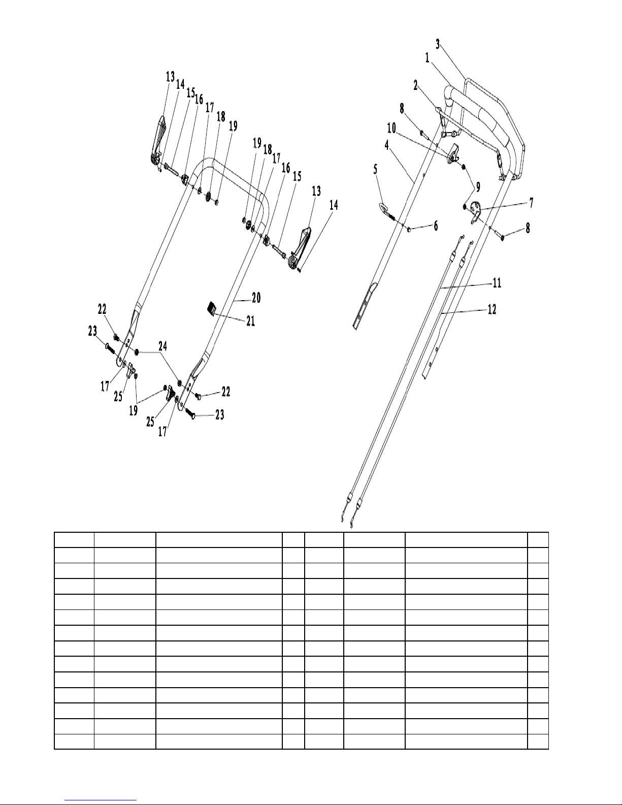
PARTS DIAGRAM - HANDLE ASSEMBLY
Item No Part Number Description Qty Item No Part Number Description Qty
1 WE114-1 Foam Handle Cover 1 14 WE113-14 Pin 6x20 2
2 WE114-2 Brake Lever 1 15 WE113-15 Bolt for Quick Lock Handle 2
3 WE114-3 Self-Propelled Lever 1 16 WE113-16 Lock for Quick Lock Handle 2
4 WE113-4 Top Handle 1 17 WE113-17 Flat Washer 8.4x16x1.6 4
5 WE113-5 Pull Rope Guide 1 18 WE113-18 Lock Nut 2
6 WE113-6 Cap NutM6/8.8 1 19 WE113-19 Hex Nut M8 4
7 WE113-7 Brake Cable Assembly Plate 1 20 WE113-20 Lower Handle 1
8 WE113-8 Bolt M6x30 2 21 WE113-21 Cable Fastener 1
9 WE113-9 Lock Nut M6/8.8 2 22 WE113-22 Hex Bolt M8x16 2
10 WE113-10 Plastic Stopper 1 23 WE113-23 Square Neck Bolt M8x30 2
11 WE113-11 Brake Cable 1 24 WE113-12 Lock Nut M8/8.8 2
12 WE114-4 Self-Propelled Cable 1 25 WE113-3 Triangle knob 2
13 WE113-13 Quick Lock Handle 2

PARTS DIAGRAM - DECK ASSEMBLY
Item No Part Number Description Qty Item No Part Number Description Qty
1 WE115-1 Deck 1 14 WE113-3 7 Hex Self-Tapping screw M6x10 6
2 WE113-25 "O" Ring 11.2x2.65 1 15 WE113-38 Height Adjustment Spring 1
3 WE113-26 Inlet 1 16 WE113-39 Height Adjustment Rod 1
4
WE113-27
Pipe Connector Nut M12x1.25 1 17 WE113-40 R Pin 1.5x25 2
5
WE113-28
Cable Stopper 1 18 WE113-41 Bolt M6x12 2
6
WE113-29
Left Handle Bracket 1 19 WE113-42 Lock Nut M6 2
7
WE113-30
Right Handle Bracket 1 20 WE113-47 Mulch Plug 1
8
WE113-31
Hex Bolt M8x14 4 21 WE115-3 B&S 500E Petrol Engine 1
9
WE113-32
Lock Nut M8 6 22 WE115-4 Side Discharge Bracket 1
10
WE115-2
Height Adjustment Board 1 23 WE115-5 Side Discharge Cover 1
11
WE113-34
Square Neck Bolt M8x15/8.8 2 24 WE115-6 Side Discharge Chute 1
12
WE113-35
Rear Drive Right Bracket 1 25 WE115-7 Side Discharge Shaft 1
13
WE113-36
Rear Drive Left Bracket 1 26 WE115-8 Side Discharge Spring 1

PARTS DIAGRAM - FRONT AXLE ASSEMBLY
Item No Part Number Description Qty
1 WE113-49 Front Axle 1
2 WE113-50 Front Wheel 2
3 WE113-51 Wheel Bearing 4
4 WE113-52 Lock Nut M8 2
5 WE113-53 Wheel Trim 2
6 WE114-5 Inner Wheel Cover 2

PARTS DIAGRAM - REAR AXLE ASSEMBLY
Item No Part Number Description Qty
1 WE113-54 Rear Axle with Height Adjustment Handle 1
2 WE115-9 Gearbox Assembly 1
3 WE114-7 Bush 2
4 WE114-8 Bearing 6001RS 2
5 WE115-10 Gasket 13x39.3x1 2
6 WE115-11 Inner Wheel Cover 2
7 WE114-11 Spring Wash er 12 6
8 WE114-12 Ratchet Washer 4
9 WE114-9 Self-Propelled Spring 1
10 WE114-14 Drive Cog L 1
11 WE114-15 Drive Cog R 1
12 WE114-16 Drive Pin 6
13 WE115-12 Rear Wheel 10" 2
14 WE113-51 Wheel Bearing 4
15 WE113-52 Lock Nut M8 2
16 WE115-13 Rear Wheel Trim 2
17 WE114-17 Drive V Belt 1
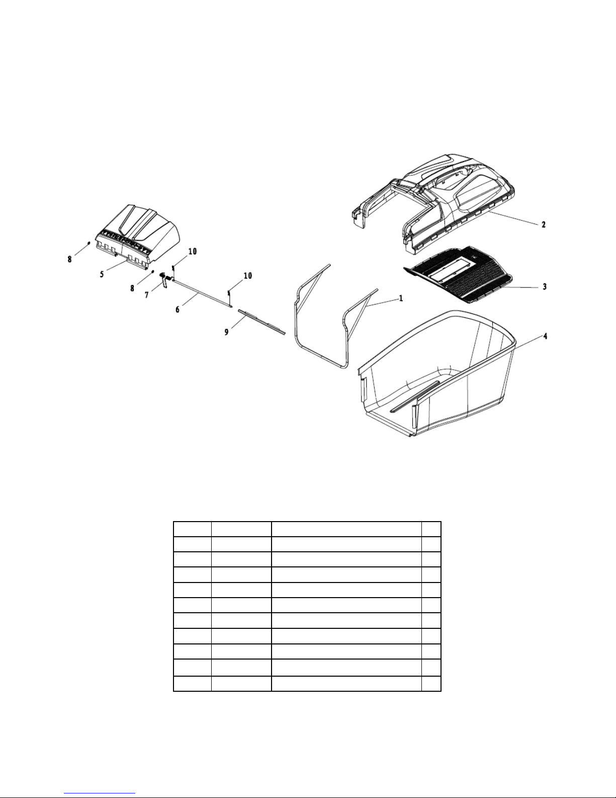
PARTS DIAGRAM - GRASS COLLECTOR ASSEMBLY
Item No Part Number Description Qty
1 WE113-58 Grass Box Frame 1
2 WE113-59 Grass Box Top 1
3 WE113-60 Filter Plate 1
4 WE113-61 60L Grass Box Bag (Unbranded) 1
5 WE113-62 Rear Discharge Cover 1
6 WE113-63 Rear Discharge Cover Shaft 1
7 WE113-64 Rear Discharge Cover Spring 1
8 WE113-65 Lock Washer 6 2
9 WE113-66 Rear Discharge Cover Dust Board 1
10 WE113-67 R Pin 1.5x25 2

PARTS DIAGRAM - BLADE ASSEMBLY
Item No Part Number Description Qty
1 WE114-18 Blade Adapte r Assy 1
2 WE113-69 18" Double Edge Blade 1
3 WE113-70 Blade Washer 1
4 WE113-71 50mm Hex Flange Bolt 1
5 WE114-19 Chassis bushing 2
6 WE114-20 Hex Self-Tapping screw 3/8-16x1ST-30 mm 2
7 WE114-21 Hex Self-Tapping screw 3/8-16x1ST 1
8 WE114-22 Belt Cover 1

EC Declaration of Conformity
We, Importer
Handy Distribution
SN3 4NS
Declare that the product
Designation: 140cc
Model: WER18HW
Complies with the following directives:
2006/42/EC - Machinery Directive
2004/108/EC - Electromagnetic Compatibility Directive
2000/14/EC amended by 2005/88/EC - Noise Emission in the Environment by Equipment for
Use Outdoors Directive.
The conformity assessment procedure followed was in accordance with
Directive 2000/14/EC
Name of the Notified Body: TÜV Rheinland (Shanghai) Co., Ltd.
Address: B1-13F No. 177, Lane 777, West Guangzhong Road, Zhabei District, Shanghai, CHINA
- Measured Sound Pressure Level: 81.4 dB (A)
- Guaranteed Sound Power Level: 96 dB (A)
Standards and technical specifications referred to:
EN 836/A3:2004
ZEK01.2-08.2008
EN ISO 14982:2009
2000/14/EC amended by 2005/88/EC - EN ISO 3744:1995, ISO 11094:1991
Authorised signatory and technical file holder
Date: 06/12/2013
Signature:
Name / title: Mr. Simon Belcher / Managing Director
Hobley Drive, Stratton St Margaret, Swindon, Wiltshire, SN3 4NS.

GUARANTEE
This product is guaranteed against manufacturing defects for a period of 24 months.
This does not cover the product where the fault is due to misuse, abuse, use in
contravention of the instructions, or where the product has been the subject of
unauthorised modifications or alterations. This warranty only covers domestic use
and will be void if the tool is used for a commercial application. In the event of a
problem with the product within the guarantee period, please contact Customer
Service on 01793 333212 or email customerservice@webblawnmowers.co.uk. If the
issue cannot be resolved over the telephone or by email, you may be referred to
your local approved service dealer.
Please keep your sales receipt as proof of purchase
Your statutory rights remain unaffected. Guarantor: Handy Distribution SN3 4NS
Whilst every effort is made to accurately represent the product, small variations in
colour, design and specification may occur. We reserve the right to alter the product
without giving notice. All images are illustrative only and may differ from the product
due to ongoing product development.

••HAND PUSH CYLINDER
HAND PUSH CYLINDER
LAWN MOWERS
LAWN MOWERS
••ELECTRIC & PETROL CYLINDER
ELECTRIC & PETROL CYLINDER
LAWN MOWERS
LAWN MOWERS
••INTERCHANGEABLE
INTERCHANGEABLE
CYLINDER CARTRIDGES
CYLINDER CARTRIDGES
••ELECTRIC & PETROL ROTARY
ELECTRIC & PETROL ROTARY
LAWN MOWERS
LAWN MOWERS
••PETROL RIDE ON
PETROL RIDE ON
LAWN MOWER
LAWN MOWER
••PETROL LAWN SCARIFIER
PETROL LAWN SCARIFIER
FIND OUT MORE AT WWW.WEBBLAWNMOWERS.CO.UK
FIND OUT MORE AT WWW.WEBBLAWNMOWERS.CO.UK
A SELECTION OF QUALITY PRODUCTS FROM OUR VAST RANGE
A SELECTION OF QUALITY PRODUCTS FROM OUR VAST RANGE


To order spare parts and see the complete range of garden
machinery and garden equipment from Webb, visit:
www.webblawnmowers.co.uk
Spares Hotline: 01793 333212
 Loading...