

Page 1
Operation/Installation Manual - WBCC Series - Page : 1
Operation/Installation Manual - WBCC Series - Page : 1
Edition dated 1st January 2004
D
I
G
I
T
A
L
C
O
N
T
R
O
L
P
A
N
E
L
F
U
N
C
T
I
O
N
I
N
G
P
R
I
N
C
I
P
L
E
S
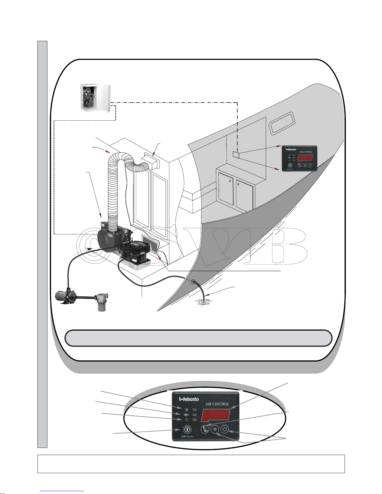
Webasto
- AIR CONDITIONING
SEA-WATER PUMP
ELETRICAL
CONTROL
BOX
SELF-CONTAINED CPAC
UNIT - 7000 TO 32000 BTU
- BLOWER EXIT TURNED
UPWARDS
FLEXIBLE AIR DUCT
TRANSITION BOX + SUPPLY
AIR-GRILLE
RETURN AIR-GRILLE
STRAINER
OVER-BOARD DISCHARGE
DIGITAL CONTROL
PANEL
DISPLAY CABLE
POWER CABLE
SELF-CONTAINED UNITS - WBCC SERIES
OPERATION AND INSTALLATION MANUAL
COOL CYCLE LED
BLOWER LED
ROOM TEMPERATURE OR
SET-POINT TEMPERATURE
OR SECONDARY FUNCTION
READ-OUT
SET-POINT MODIFICATION
KEYS
F/BLOWER KEY - GIVES
ACCESS TO BLOWER SPEED
CONTROL AND SECONDARY
FUNCTIONS
HEAT CYCLE LED
ON/OFF KEY
SELF CONTAINED UNITS
NNEEWW EELLEECCTTRROONNIICCSS -- 22000000 SSEERRIIEESS
19.4
Page 2

Operation/Installation Manual - WBCC Series - Page : 2
Operation/Installation Manual - WBCC Series - Page : 2
Edition dated 1st January 2004
SELF-CONTAINED AIR-CONDITIONING UNITS - WBCC SERIES
OPERATION AND INSTALLATION MANUAL
C O N T E N T S
Page
1) General Information ..................................................................................................
2) Digital Control - Operation Guidelines .....................................................................
2.1 - Digital Display <AIR CONTROL> - Basic Commands ...................................
3) Secondary Commandes by F/Blower key .................................................................
4) Visual Error Codes - Digital Display ........................................................................
5) Central Blower Control ...........................................................................................
6) Programmable Functions ...........................................................................................
6.1 - Digital Display <AIR CONTROL> - Programming access .............................
7) Pratical Installation Guide - Components (Pumps, accessories, etc) .......................
8) Routine Checks ........................................................................................................
8A) Trouble Shooting .....................................................................................................
9) Air-Ducting and V entilation .......................................................................................
10) Wirings Schematics .................................................................................................
10.1 - Wiring diagram - WBCC 5 to 16 - single phase - Rotary compressors ...........
10.2 - Wiring diagram - WBCC 24 and 30 - single phase - Rotary/Scroll compr. .....
10.3 - Wiring diagram - WBCC 5 to 16 - single phase - Piston Compr. (<2000) .....
10.3 - Wiring diagram - Wiring Running Capacitor - Blowers ...............................
3
4
4
5
5
5
7
7
8
9
9
10
11
11
12
13
13
Page 3
1. GENERAL INFORMATION
All WEBASTO air conditioning units are
controlled by a Digital Display <AIR
CONTROL> which gives access to all
functions necessary for the normal operation of the unit and attached accessories
(blowers, pumps, etc).
All WEBASTO air conditioning units are
sea-water cooled by means of an AC seawater pump.
In order to start the system you only need
to press the <POWER> key on the digital
display.
From there on the electronic control unit
takes care of the progressive starting up of
the air conditioning unit as well as it normal functioning.
The digital display will show the present
air temperature of the cabin in which the
digital display is situated or where the
main temperature sensor is located (in
case the optional secondary temperature
sensor is used).
After a delay of approx. 20 seconds the
display will indicate the cycle in which
operation will start i.e. <COOL> or
<HEAT>. The choice will depend upon
the set-point temperature and the air-temperature as measured by the display panel.
After a further delay of approx. 50 seconds the compressor(s) will start up and
the normal operation cycle will begin.
2000 SERIES DIGITAL DISPLAY
As from September 2000 all WEBASTO air
conditioning units are controlled by a Digital
Display <AIR CONTROL> 2000 SERIES
which gives access to all functions necessary
for the normal operation of the unit and
attached accessories (blowers, pumps, etc).
2000 Series Electronic Controls are easily
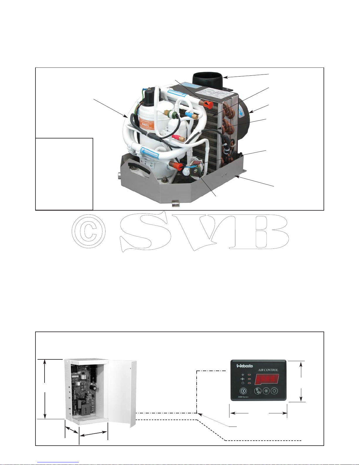
All air-conditioning units based on hermetic compressors function on the same
principle : a compressor compresses the
refrigerant gas which is then condensed to
liquid when passing through a sea-water
cooled condenser. Subsequently the liquid
refrigerant is injected through a small
nozzle and evaporates. This evaporation
process produces the refrigeration effect.
The evaporation takes place in a tubular
finned coil (also called : evaporator coil).
A blower forces the air through the evap-
orator coil.
While passing through the evaporator the
temperature of the air is lowered by
approximately 15 °C.
So far for the general principles.
HOW DOES IT WORK ?
COPPER TUBING OF
FINNED EVAPORATOR
FINNED TUBULAR
EVAPORATOR COIL
CONDENSER
EXIT
BLOWER EXIT
BLOWER
STAINLESS
STEEL DRAIN
PAN
CUPRO-NICKEL
CONDENSER
CONDENSER
ENTRY
REVERSED CYCLE VALVE
COOL/HEAT
HEAT CYCLE
It is quite possible to produce heat
with an air-conditioning unit. For
this purpose a 4-way reversed cycle
valve is added. During heat cycle
operation the sea-water condenser
effectively becomes the evaporator
and cools down the sea-water. The
finned evaporator becomes the condenser and produces heat to approx.
45/50° C.
Heat cycle becomes inefficient
when the outside water temperature
drops below 6° C approx.
STANDARD ELECTRICAL ACCESSORIES
ELECTRICAL CONTROL BOX
DIGITAL DISPLAY PANEL
MINIMUM STANDARD CONTROL ELEMENTS DELIVERED FOR ALL CPAC SELF-CONTAINED UNITS
Summary : 1 Alu control box + 1 display cable + 1 digital control panel (External air-sensor is optional)
104
DISPLAY CABLE
OPTIONAL EXTERNAL AIR SENSOR
76
Operation/Installation Manual - WBCC Series - Page : 3
Operation/Installation Manual - WBCC Series - Page : 3
Edition dated 1st January 2004
P
P = 132 mm
262
130
19.4
Page 4
recognized by the inscription <2000 Series>
at the bottom left hand corner of each digital
display.
All WEBASTO air conditioning units are
sea-water cooled by means of an AC seawater pump.
In order to start the system you only need to
press the <POWER> key on the digital display.
From there on the electronic control unit
takes care of the progressive starting up of
the air conditioning components as well as it
normal functioning.
The digital display will show the present
room temperature of the cabin in which the
digital display is situated or where the main
temperature sensor is located (in case the
optional secondary temperature sensor is
used).
The WEBASTO <AIR CONTROL> digital
display allows gives access to information
and controls at three distinct levels :
Immediate Access - Level 1 :
1) Room temperature read-out in the main 4
LED display window
2) 3 small LED’s to the left indicating the
operating cycle presently active :
- Cool cycle only operation.
- Automatic cycle switching governed by
end-user entered set-point temperature.
- Heat cycle only operation.
3) 2 set-point keys give immediate access
to the thermostatic set-points for blowercontrol (“Sun” and “Snow” key).
These keys are also used to alter program-
ming values - see here-after chapter 6.
Secondary commands and info Level 2 :
4) The F/Blower key gives immediate access
to a number of secondary commands which
need to be accessed frequently for day to day
operation.
First access is to blower speed control, then
evaporator temperature read-out, etc.
See hereafter drawing 2.1 for complete list.
Programming Commands - Level 3 :
A number of programming commands that
do not need to be accessed for day to day
operation are hidden and require a special
procedure to enable access and modification.
An access code can be enforced to avoid
accidental modification of programming values.
See Chapter 6 - Page 7.
Start-up delay :
After pushing the on/off key the LED’s will
display <ON> while initializing the system.
Push again to stop operation - the display
will briefly show <off> before extinction.
The adequate LED to the left (heat, cool , etc)
will come on after approx. 20 seconds and
compressor operation will start after approx.
60 seconds.
The sea-water circulation pump will come on
approx. 9 seconds before compressor start.
Modification of set-point temperature :
The set-point temperature i.e. the temperature desired by the operator for blower operation directly connected to the TCC controller card, can be modified as following :
Press and hold one of the set-point selector
keys and wait until the new desired set-point
temperature is obtained. Release the setpoint key.
The display will return to normal room temperature read-out after approx. 5 seconds.
See drawing 2.1 - page 4 for visual operation
guide.
Non-volatile memory keeps last settings.
Special New Features - 2000 Series :
A) Automatic blank/sleep mode -
programmable time delay. Factory default : 15
minutes. While in blank/sleep mode the cycle
LED flashes discretely every 20 seconds. To
go back to normal operation push any key.
Operation/Installation Manual - WBCC Series - Page : 4
Operation/Installation Manual - WBCC Series - Page : 4
Edition dated 1st January 2004
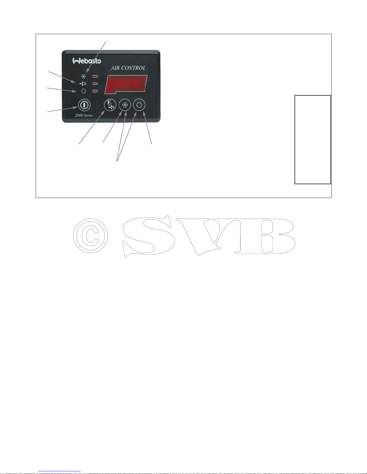
2 - DIGITAL WBCC/BLOWER CONTROL - GENERAL PRINCIPLES
BASIC COMMANDS :
1 - Press to turn on - press again to turn off.
2 - Press to read set-point temperature - hold to raise
set-point temperature.
3 - Press to read set-point temperature - hold to lower
set-point temperature.
4 - Led indicating system working in cool mode
5 - Led indicating manual blower speed control is active
6 - Led indicating system working in heat mode
7 - Function/Blower Key - immediate access to :
- blower speed control .............................................
- evaporator temperature read-out ...........................
- manual cycle choice (cool, heat, auto-reverse) ....
- AC voltage read-out ..............................................
- selective on/off compressors 1 to 4 ......................
- starting priority compressors 1 to 4 .....................
- automatic dehumidifying cycle during absence
- display time secondary functions accessible by
F/Blower key
8 - Access to hidden programming functions - see
page 7.
1
3
8 -
Push Both Keys Simultaneously
after Display Extinction
DRAWING 2.1 - BASIC AND SECONDARY COMMANDS
4
5
6
7
2
*
bb AA
HH1133..22
*
FF 33
UU223300
11CC0011
etc
PP112233
etc
*
dd 00
*
tt 11
*Default Values
24.2
Page 5

B) Calibrate all blower speed settings
in real time mode.
It is now possible to calibrate all speed set-
tings (1 to 5) before actually putting the system into service.
To do so entrer programming mode with setpoint at 15° C.; proceed to following line i.e.
code <6> = speed 5 (max).
The blower will start to function as soon as
you access code <6>.
Alter value to the right of code <6> and
blower speed will immediately change in
real time. When satisfied go to follo wing line
<7> = speed 4 and do the same.
Proceed until lowest speed N° 1 and go back
again to speed N° 5 if not satisfied.
When all speeds are programmed according
to need, validate by pushing on/off key
(<memo> will be displayed briefly). See also
page 8 - programming access.
Attention : Never program speeds
so low that the blower is in danger
of stopping or will not re-start at
that setting.
This will inevitably entail motorwindings burn-out and will not be
covered by WEBASTO warranty.
C) Automatice De-Icing Control :
During intermediate seasons (spring,
autumn) when moderate temperature
conditions prevail, there is a definite risk
of icing the evaporator coil in cool mode
and pressure safety cut-outs in heat mode.
To allow maximum blower speed variation and still function within a normal
operating window, the TCC card is
equipped with a second temperature sensor which reads the exact evaporator coil
temperature.
Whenever coil temperature approaches
the danger zone, blower speed is
increased to half speed; if that is not sufficient the micro-processor will stop compressor operation for pre-determined
intervals and will resume normal operation when coil temperature has moved
back to within normal operating values.
This feature is completely transparent to
the end-user without an error code display; in short this feature belongs to the
normal operating procedures in the same
way as the temperature set-points.
D) Infra-Red Remote Control :
Infra-red remote control can be obtained as
an option. This remote control is based on the
standard protocols also used by TV and other
appliances. Although the WEBASTO controls have been chosen so as to avoid interference with most TV models, the end-user
should be aware that in certain cases interference may occur with TV sets or other appliances.
In general it is therefore advisable to avoid
locating a WEBAST O Air Control panel next
to other appliances using infra-red control
units whenever it is planned to use infra-red
control mode.
D) ACCESS CODE :
The end-user can deny access to all program
settings by introducing an access code (see
page 8 - code <b>). Blower speed and setpoints always remain accessible.
Once an access code is validated, the digital
panel will show <Code> if the end-user tries
to access other functions then blower speed
or set-point. To gain full access push the sun
key to reach the code number as programmed
and push the <F> key again to gain access to
full program settings.
3. SECONDARY COMMANDS :
The F/Blower key gives immediate access to
commands and display necessary for day to
day operation. When pushing the F key you
will see to the left a code which indicates the
type of display or command and to the right
the present value.
In order of appearance here-after an explanation of these commands/displays :
a) Blower speed control : < b A>
(0,1,2,3,4,5)
This command preceeded by the letter b
(blower) allows the following settings :
A = automatic blower speed adjusted to tem-
perature differential.
1 to 5 = Manual Speed Control
Speed control is in real time mode i.e.
changes are effected immediately without
any validation procedure.
Attention : All following func-
tions need validation before a new
value is accepted.
Validation is obtained by pushing
the F key again and by going to the
next function line.
Then final validation will occur
automatically when the display
goes back to room temperature
read-out or final validation can be
forced by pushing the on/off key
briefly while still in F mode.
Validation is witnessed by the brief
display of the message <memo>.
b) Read out of evaporator coil temperature :
<E10.2> (10.2 ° C) - example.
c) Cycle mode choice : <F 3> (1 to 4)
The following cycle modes can be choosen
manually :
1 = cool cycle only
2 = heat cycle only
3 = automatic cycle switching with reversible
compressor
4 = automatic cycle switching without
reversible compressor
d) AC Voltage read-out : < U232>
(232 Volts) - example
e) Manual on/off Compressor 1 : <1C01>
<1C01> = Compressor 1 on
<1C00> = Compressor 1 off
f) Manual on/off Compressor 2 : <2C01>
<2C01> = on
<2C00> = off
Idem for compressors 3 and 4 - <3C01> and
<4C01>.
g) Starting Priority Compressors 1 to 4 :
<P123> = 1,2,3,4 ; <P341>=3,4,1,2
<P A> = automatic priority rotation; when
in this priotity mode, the starting
order will be changed every next
restart after thermostatic cut-out.
h) Starting delay between compressors :
<L 9> (9 seconds) - programmable
between 1 and 9 seconds.
i) Automatic dehumidification while absent.
factory default setting : <d 0>
0 = non active
1 = 1 cycle per 24H
2 = 2 cycles per 24H etc
k) display time of secondary functions (F/
Blower key) by periods of 20 seconds.
<t 1> (factory default setting) = display
time 20 seconds.
4. VISUAL ERROR CODES DIGITAL DISPLAY
The following malfunctions will be displayed directly on the digital display by a
Operation/Installation Manual - WBCC Series - Page : 5
Operation/Installation Manual - WBCC Series - Page : 5
Edition dated 1st January 2004
Page 6

Operation/Installation Manual - WBCC Series - Page : 6
Operation/Installation Manual - WBCC Series - Page : 6
Edition dated 1st January 2004
code and will be followed by a system halt.
Whenever any of these codes appear the system is stopped for approx. 60 seconds and
then a re-start is attempted.
If for more than 30 minutes the same malfunction occurs, the system will be stopped
completely and the error-code will become
steady.
No more re-starts will be attempted and the
user will have to re-set the system by pushing
the ON/OFF switch or by temporarily cutting
out the AC supply to the system.
List of error-codes and nature of malfunction :
Code <AAA> :
Persistent low voltage (voltage below 195V)
for more than 5 seconds - (see also hereafter
- Trouble-Shooting - Page 9).
Code A01 to A08 *) :
Pressure safety cut-out of compressors 1 to 4.
The HP and BP (if present) safety controls
are directly controlled by the micro-processor inclusive the time-delays for re-start, etc.
*) Standard TCC controller
cards
have only 1 outlet for 1 single com-
pressor. However the embedded microprocessor program can operate up to 4 CPAC
units from 1 single controller card. This special controller card can be obtained on special request but is not standard delivery.
Error codes displayed and probable nature of
anomaly.
<A01> : BP (low pressure) cut out - com-
pressor 1 - probable causes :
- insufficient refrigerant charging
level
- abnormal sea-water temperature
conditions in heat cycle (sea-water
temperatures under 6° C. approx.)
- first start-up in heat cycle with very
low chilled water circuit temperatures (below 8° C approx.).
ATTENTION:
models CPAC5 to 16 do
not have a low pressure safety switch (BP);
therefore if you see a A01 warning on such
model, it can only be an electrical connection
problem on the grey 3 pole HP/BP connector
on the TCC controller card. Check that the
connector is properly seated and that the BP
strap is properly tightened.
<A02> : HP (high pressure) cut out - com-
pressor 1 - probable causes :
- insufficient or non-existent sea-
water cooling - check sea-water
pump.
- too much refrigerant in system call specialist
- abnormal sea water temperature
conditions in heat cycle (sea-water
temperatures above 17° C approx.)
<A03> : BP cut out - compressor 2 - for
probable causes see <A01>
<A04> : HP cut out - compressor 2 - see
<A02>
<A05> to <A08> - same as above for compressors 3 and 4 (if present).
If any of these error codes appear too frequently and no appropriate action can be
taken with the available means on board, it is
necessary to call a specialist.
Do not insist with manual re-starts in such
case as this may cause major damage to the
principal components (compressors, pumps,
etc).
<A09> - absent or defective external or inter-
nal (Display Face) air sensor
<A10> - absent or defective evaporator
temperature coil sensor.
<CA11> - all compressor(s) have been disac-
tivated by soft - <F> procedure :
<1C00>, <2C00>, etc
To re-activate, reprogram as
follows : <1C01>, etc
<EA11> - compressor stopped by de-icing
control - automatic restart - this code does
not entail a complete system halt and will
only be visible when in reading out the evaporator temperature (F key - line E).
5. CENTRAL BLOWER CONTROL
The central <AIR CONTROL> digital display also directly controls the blower(s) of
the evaporator(s).
For all CPAC systems, there are two modes
of blower control and operation :
- thermostatic interruption of blower operation as soon as the desired set-point
temperature has been reached.
- un-interrupted blower operation regardless of thermostatic compressor control.
The choice between these two functioning
modes can be programmed directly by the
end user - see here-after Chapter 6 - programming procedures.
The digital control is initially programmed
by the manufacturer in second - i.e. un-interrupted blower operation.
Blower control can be manual with 5 different speed levels or automatic; in this case
blower speed will be governed by the temperature differential with the set-point temperature.
Page 7

Operation/Installation Manual - WBCC Series - Page : 7
Operation/Installation Manual - WBCC Series - Page : 7
Edition dated 1st January 2004
To gain access to the hidden programming
functions proceed as following :
Raise set-point to max. value i.e. 29° C (or
alternatively to lowest value i.e. 15° C) push Off key to extinguish digital display.
Press <snow> and <sun> key simultaneously
for approx. 3 seconds until you see to the left
of the display window a single number code
indicating the programming line presently
valid and to the right the programming value.
To go to the next programming line, push the
<F> key.
If you modify the programming value of any
line, you need to validate this new value by
pushing the <F> key again to move to the
next line. This step will validate and memorize the changes made.
1° Functions accessible by raising the setpoint to 29° C. :
Code <0> - factory setting : -1° Celsius -
lower set-point temperature of the ev aporator
coil temperature in cool cycle. Gives the
compressor cut-out point when the “deicing” procedure is activated..
Adjustment range : between -5° C. and +10°
C.
Code <1> - factory setting : +7° Celsius higher set-point temperature of de-icing procedure. This value gives the re-start point of
the compressor(s) after an interruption when
in de-icing mode.
Set-point temperature adjustable between
0°C. and +12° C.
Code <2> - factory setting : 40° C. higher
set-point temperature of the “de-icing” procedure in relation to the evap. coil temeprature when in heat cycle (to avoid HP cutouts). Gives the cut-out point of the compressor(s) when functioning in heat cycle.
Set-point temperature adjustable between
35° and 50° C.
Code <3> -factory setting : 35° C. - lower
set-point temperature of coil temperature cutin when in heat cycle. Gives the cut-in point
of the compressor(s) after an interruption
(“de-icing” procedure) when functioning in
heat cycle.
Set-point temperature adjustable between
30° and 50° C.
Code <4> - pre-programmed value : 0 - calibration of temperature display of the evaporator coil temperature read-out - correction
possible between -9° to +9° Celsius.
Code <5> - factory setting : 15 - time delay
in minutes before the digital display goes
into blank/sleep mode. Cycle LED flashes
discretely to indicate system is operational.
Code <6> - factory setting : 1 - time delay
first start up in seconds. To stage starting of
several CPAC units when switching on AC
supply after an interruption.
Code <7> - factory setting : 0 - calibration
of room temperature read-out. Possible
between +9 and -9° C.
Code <8> - pre-programmed value : 0.
Factory calibration of AC voltage 50 Hz as
displayed on the digital panel when accessing the secondary commands - F key.
Correction between -20 and +20 Volt.
Code <9> - pre-programmed value : 1 Time delay before re-start in minutes after a
compressor stop when in “de-icing” procedure. (both for cool and heat cycle).
Code <A> - pre-programmed value : N/A.
Factory calibration of AC voltage 60 Hz as
displayed on the digital panel when access-
ing the secondary commands by the F key.
Correction between -30 and +20 Volt
Code <b> - Program version
Re-intializing of factory default settings :
It is possible to force the program to re-initialize all program values to factory default
settings by the following procedure :
When reading the <b> line as above (through
the 29° set-point), push the <sun> key; continue to push; the program version will start
to flash. Keep the <sun> key pushed down
until the display shows <init>.
Leave programming mode by pushing
On/Off key - you are now back to the factory
default settings.
Attention :
this procedure should never be
attempted for any program version below a
value of 1.00 - i.e. for
<b0.12>
never
attempt to reinitialize the default settings :
your controller card will lock itself and cannot be unlocked.
On the contrary - example : program version
<b1.02>
or
<b2.03>
:OK to re-initialize.
2° Functions accessible when lowering
the set-point temperature to 15° C :
Code <0> - pre-programmed value : 195 low voltage cut-out value AC.
Time delay is 5 seconds approx. i.e. the low
voltage situation will have to persist during
more than 5 seconds before cut-out occurs.
After cut-out the electronic controller resets
and will start a new cycle. So a renewed
attempt to start the compressor will occur
after approx. 90 seconds.
PROGRAMMING MODE :
To enter programming mode : raise or lower set-point to 29 or 15° C.
Turn off system by pressing <Power> key - 14.
Press simultaneously keys <11>. The display will show to the left
<15>, the number code of the current programming line and to the right
<16> the present value.
To validate and memorize modified parameters press the <F> key (12)
and proceed to the following programming line.
6 - DIGITAL DISPLAY <AIR CONTROL> - PROGRAMMING ACCESS
00 44..66
11
12
14
15
16
Page 8

Operation/Installation Manual - WBCC Series - Page : 8
Operation/Installation Manual - WBCC Series - Page : 8
Edition dated 1st January 2004
During low-voltage cut-out the display panel
will show the 3 letters <AAA>.
Programming of a cut-out level below 195 V
is done at the entire risk of the operator. It
should be noted that almost all compressor
manufacturers decline all responsibility for
defects resulting from operating the compressors below 195V AC.
Code <1> - factory setting : 0 - infra-red
remote control :
0 = infra-red remote control disabled (in this
mode no interference is possible with other
infra-red commands)
1 = infra-red remote control active
Code <2> : Blower type : Centrifugal or
Cross-Flow. Factory default : 1
0 = centrifugal blowers only
1 = centrifugal + cross-flow
Code <3> - pre-programmed value : 1 basic choice of blower control :
0 - thermostatic control of blower operation
i.e. blower operation will be interrupted thermostatically when reaching the appropriate
set-point.
1 - un-interrupted blower operation regardless of the thermostatic control.
Code <4> - factory setting : 1 - Choice
between integrated air sensor and external air
sensor :
1 - air sensor integrated in digital display
0 - external air sensor
Code <5> - Celsius or Fahrenheit display -
factory setting : 1
0 = Celsius read-out
1 = Fahrenheit read-out
Code <6> : modification speed N° 5 (max)
Code <7> : idem speed N° 4
Code <8> : idem speed N° 3
Code <9> : idem speed N° 2
Code <A> : idem speed N° 1
Code <b> - factory setting : 0 - access code
for programming mode.
0 = no access code required
1 to 99 = access code/number activated
*) Factory access code : in case the system is
blocked and the access code cannot be found,
you can acces the programming line by using
the factory code number : 64
Code <c> - factory setting : 1 - duration in
minutes of heat cycle dehumidifying cycle.
Code <d> - factory setting : 1 - duration in
minutes of cool cycle dehumidifying cycle.
DIPSWITCHES :
The TCC controller card has a dipswitch
arrangement which should be set and maintained according to the following settings :
1) TCC controller for single compressor ,
without the secondary card for compressors 3
and 4 :
Attention :
if dipswitches are not set
according to the above configurations i.e.
according to the number of compressors
effectively on line, the TCC controller card
may behave in unpredictable manner :
- the initialisation <init> can not be completed - card remains locked on start-up.
- HP/BP alarms for non--existing compressors.
7. PRACTICAL INSTALLATION GUIDE
1) Sea-water cooling :
Install the pump/strainer assembly in such
a manner that a natural gentle upwards
slope exists from the sea-cock to the pump
itself. See also drawing hereabove ref. 6.1.
It is strongly recommended to install an
air-bleeder system both in the suction line
as well as immediately after the discharge
outlet of the pump. The advice is especially valid for pumps WEBASTO250/350/1000. The WEBASTO1500/2000 and Calpeda pumps 0.5HP
to 1 HP generally will not require a bleeder system to ensure proper operation.
For ALL boats it is strongly recommended to install a water-scoop at the entry of
the sea-cock and directed towards the bow
of the boat so that at speed positive pressure builds up in the supply line to the seawater pump.
2) Sea-water cooling exits :
Provide for a separate sea-water exit for
each air-conditioning unit installed even if
only one pump provides cooling for all
units.
1
23
4
OPEN
ATT. DIPSWITCH SETTINGS
BLACK = PUSHED DOWN
TO OVER-BOARD OUTLET APPROX. 10 CMS ABOVE WATER-LINE
INSTALLATION OF BLEEDER ADVISABLE
MEMBRANE PUMP CLD125 L7 12/24V
SITUATED JUST BELOW WATER-LINE
SEA-WATER STRAINER
SUCTION GENTLY UPWARDS TO
FACILITATE PRIMING
CLAM-SHELL TYPE THRU-HULL FITTING
WITH SLOTS DIRECTED TOWARDS BOW TO OBTAIN POSITIVE PRESSURE IN SUCTION LINE
NB - ALL PIPING AS SHORT AS POSSIBLE WITHOUT
KINKS NOR SYPHONS
WATER-LINE
7.1 - INSTALLATION AND POSITIONING OF SEAWATER PUMP AND ACCESSORIES
Page 9

Introduce shut-off valves for each unit if 1
pump provides cooling for more than 1
air-conditioning unit.
This will allow easy priming of the circuit
and also calibration of the sea-water flow
for each air-conditioning unit in case of
imbalance in the water tubing lengths.
3) Evaporator coils :
The finned coils of the evaporators and/or
air-handlers are fragile. When during
installation the fins of these coils are damaged, take care to re-align the fins in
order not to impair proper air-flow.
4) Air-ducts :
Flexible air-ducts need to be of good quality with sufficiently strong steel or plastic
re-inforcement. Do not restrict air-flow by
bending the air-ducts too tightly or by
accidental local deformation.
Do not install air-ducts of excessive
lengths (+ 2.5 ml); the pressure loss and
consequent reduction of air-flow will seriously diminish the efficiency of the installation.
8. ROUTINE CHECKS
When starting up an air conditioning unit
it is advisable to carry out a certain number of routine checks to ensure proper
functioning of the unit.
- always check (especially after a long
absence) the functioning of the sea water
cooling system. Immediately stop the system if no sea-water comes out of the pump
exit after compressor starts up.
- periodically check the air filter in the
return air grilles. Clean if necessay.
- check condensation drain from the evaporator drain pan.
- take care not to damage the air-ducts. A
damaged air-duct may stop air flow
through the evaporator, freeze up the
evaporator and subsequently damage the
compressor.
- when preparing for winter lay-up take
care to rince all sea-water circuits with a
fresh-water/glycol solution (25% or more
depending on local winter conditions).
8A. TROUBLE SHOOTING
1) No sign of live : check main electrical
supply, fuses, etc.
2) The digital display shows 3 lettres
<AAA>. This means a persistent state of
low voltage (less than 195 V AC). The
system will re-start as soon as the voltage
level climbs above cut-out level and the
system will then re-start after a timedelay of 1 minute approx.
3) The compressor will start but no seawater circulation can be observed :
- check sea-cock to sea-water pump.
- check sea-water strainer
- check if pump turns
- if the pump does not turn with the compressor working, check power-supply
from the main control unit box to the
pump.
4) Compressor and pump work but no correct operation in either cool or heat cycle :
- check proper air ventilation - blowers. If
air flow completely stops with the compressor working, the evaporator coils may
freeze up completely,obstruing all air circulation.
- during the heat cycle with too slow a seawater circulation you may actually freeze
up the sea-water in the cupro-nickel condenser and completely block the system.
- check voltage level. Do not operate a
system with a persistent voltage level
below 195 V AC.
- check freon charge if operation is still
not satisfactory, after having checked all
the above points.
5) The compressor works but is subject to
intermittent stops without having attained
the desired set-point temperature.
- the HP and BP (if present) pressure safety switches stop the compressor because
of abnormal working pressures either on
the high or on the low side. Check proper
functioning of the cooling circuit. Check
ventilator/blower system for obstructions.
- incorrect freon charge (over-charge or
insufficient charge level).
See also here-above : Error codes/interrupted system operation.
6) The heat cycle takes very long to get
started.
- normal if the sea-water temperature is
very low. If sea-water temperature drops
below approx. 8° C. the heat cycle
becomes much less effective and takes
long to get properly started.
* * *
Operation/Installation Manual - WBCC Series - Page : 9
Operation/Installation Manual - WBCC Series - Page : 9
Edition dated 1st January 2004
Page 10

Operation/Installation Manual - WBCC Series - Page : 10
Operation/Installation Manual - WBCC Series - Page : 10
Edition dated 1st January 2004
9 - AIR DUCTING - VENTILATION
1) MINIMUM AIR-GRILLE SECTIONS
In order to obtain an acceptable noise level at
max. blower speed certain requirements as
regards grille and ducts sections should be
observed.
Also the size of the transition boxe behind
the supply air-grille is important.
See table here-under to choose correct grille
sections according to BTU rating.
2) DUCT TYPE
Flexible air-ducts should be of high quality
with sufficiently strong steel spiral reinforcement to avoid accidental crushing.
Spiral type ducts should be extended to their
maximum possible length to obtain max.
interior smoothness.
For very long duct sections preference should
be given to rigid ducts (in PVC for example)
which offer a far greater smoothness than
flexible spiral type ducting and therefore will
greatly reduce internal friction.
For very short lengths non-insulated ducts
may possibly be used. Over greater lengths it
is advisable to use insulted type ducts to
avoid condensation on the outside of the airducts.
AIR/HANDLER-CPAC SUPPLY AIR GRILLE RETURN AIR GRILLE DUCT DIAM. DUCT DIAM.
MODEL MODEL/ SECTION cm² MODEL/SECTION cm² <1.8 M DUCT LEN. >1.8 M DUCT LEN.
4000/4500 BTU
6000 BTU
9000 BTU
12000 BTU
16000 BTU or
16000 BTU
24000 BTU
32000 BTU
1 x 8x4” 150 cm²
1 x 10x4” 190 cm²
1 x 12x4” 235 cm²
1 x 10x5” 250 cm²
1 x 12x6” 390 cm²
2 x 10x4” 380 cm²
2 x 10x5” 500 cm²
2 x 12x5” 650 cm²
1 x 12x5” 325 cm²
1 x 11x8” 490 cm²
1 x 11x8” 490 cm²
1 x 14x7” 550 cm² or
1 x 14x10” 800 cm2
1 x 14x12” 1000 cm²
2 x 14x10” 1600 cm²
80 mm
100 mm
100 mm
125 mm
125 mm
125 mm
2 x 125 mm
2 x 125 mm
100 mm
125 mm
125 mm
150 mm
150 mm
150 mm
2 x 150 mm
2 x 150 mm
3) BLOWER OUTLETS
90° turns with flexible ducts directly from
blower outlets should be avoided at all costs
as they introduce severe restrictions in the
air-flow.
All WEBASTO blowers (except on 24000
BTU models) can be rotated through 45°
steps so as to obtain a straight-line outlet
from the blower. This facility should be used
whenever possible.
See also drawing to the right.
4) TRANSITION BOXES
Transition boxes behind supply air-grilles
essentially serve the following purpose :
Serve as an expansion volume for the airflow to be reduced in velocity and therefore
reduce air noise when crossing the outlet
louvres.
It follows therefore that the depth of the transition box is an important factor to allow dispersion of the air-flow
The table to the right gives the necessary
information as to the minimum dimensions
advisable for such transition boxes.
5) RETURN GRILLE OFFSET
It is best to avoid placing a return air grille
directly opposite the finned coil surface of an
air-handler. This will inevitably allow propagation of direct blower-motor noise through
the grille.
Always try to offset the grille so as to chi-
cane the return air to the coil inlet.
This will lower direct noise propagation in a
significant manner.
AIR FLOW
AIR FLOW
BLOWER ROTATED TO
MINIMZE FRICTON LOSSES
H
H
DUCT DIAM. MINIMUM VALUE OF “H”
80 mm 100 mm
100 mm 120 mm
125 mm 140 mm
150 mm 165 mm
TRANSITION BOX INFORMATION
Deflection curve for longitudinal
entry transition boxes
NB : For duct lengths over 1.80 ml, it may be possible to use the nominal duct diameter (for example 100 mm - 6000 BTU
model), if instead of spiral type flexible ducts, rigid perfectly smooth interior ducts are used.
ROTATABLE BLOWER OUTLETS
Page 11

Operation/Installation Manual - WBCC Series - Page : 11
Operation/Installation Manual - WBCC Series - Page : 11
Edition dated 1st January 2004
10 - W I R I N G D I A G R A M S
DIPSWITCH SELECTOR
DISPLAY CABLE CONNECTOR
EXTERNAL AIR TEMP. SENSOR
EVAP. COIL TEMP. SENSOR
SEAWATER
PUMP 230V
SUPPLY
GND
BLOWER
REVER. CYCLE
VALVE
HP SAFETY
SWITCH
C
R
S
RUN
CAPAC.
TERMINAL
STRIP
230V AC
230V
HP
BP
COMP1
VALVE
FAN
COMP1
FAN
VALVE
PUMP1
GND
PUMP1
HARD
START
CAP.
10.1 - Wiring diagram WBCC 5000 T O 16000 BTU (Rotary Comp.) - single phase
1
23
4
OPEN
ATT. DIPSWITCH SETTINGS
BLACK = PUSHED DOWN
Page 12

Operation/Installation Manual - WBCC Series - Page : 12
Operation/Installation Manual - WBCC Series - Page : 12
Edition dated 1st January 2004
RUN
CAPAC.
BLOWER
REVER. CYCLE
VALVE
HP BP
C
R
S
SEAWATER
PUMP
230V
SUPPLY
GND
GND
DIPSWITCH SELECTOR
DISPLAY CABLE CONNECTOR
EXTERNAL AIR TEMP. SENSOR
EVAP. COIL TEMP. SENSOR
BP
HP
230V AC
230V
COMP1
VALVE
FAN
COMP1
PUMP1
FAN
VALVE
PUMP1
TERMINAL
STRIP
HARD
START
CAP.
10.2 - ELECTRICAL WIRING - WBCC 24 TO 30 - SINGLE-PHASE
1
23
4
OPEN
ATT. DIPSWITCH SETTINGS
BLACK = PUSHED DOWN
Page 13

DIPSWITCH SELECTOR
RUN
CAPACIT.
START
CAPAC.
START RELAY
5
2
1
R
C
S
BLOWER
REVER. CYCLE
VALVE
HP SAFETY
SWITCH
SEA-WATER PUMP
TERMINAL STRIP
230 V AC
SUPPLY
PUMP1
VALVE
FAN
COMP1
230V AC
230V
FAN
COMP1
HP
BP
PUMP1
VALVE
GND
DISPLAY CABLE CONNECTOR
EXTERNAL AIR TEMP. SENSOR
EVAPORATOR COIL TEMP. SENSOR
Operation/Installation Manual - WBCC Series - Page : 13
Operation/Installation Manual - WBCC Series - Page : 13
Edition dated 1st January 2004
10.3 - ELECTRICAL WIRING - WBCC 7 TO 16 - 1 PHASE - PISTON COMPR.
1
23
4
OPEN
ATT. DIPSWITCH SETTINGS
BLACK = PUSHED DOWN
10.4 - WIRING SCHEMATICS - RUNNING
CAPACITORS FOR BLOWER MOTERS -
ECOFIT/EBM
PHASE
NEUTRAL
BROWN
WIRE
CONNECTION
BLACK
BLACK
GND WIRE
CABLE FROM
BLOWER MOTER
BLUE
230V SUPPLY
RUNNING
CAPACITOR
Page 14

WEBASTO-REPRESENTATIVES - WEBASTO-VERTRETUNGEN
Germany -Deutschland
Bayern, Webasto AG
Baden-Würtemberg, Business Unit SPM
Hessen (teilweise), Niederlassung Süd
Saarland, Kraillinger Strasse 5, D-82131 Stockdorf
Rheinland Pfalz Tel. +49 89 85794-789, Fax +49 89 85794-702
Australia- Australien
AUS-2229 NSW Caringbah Webasto Product Australia Pty. Ltd.
4/65 Captain Cook Drive
Tel. +61 295 404811, Fax +61 295 404316
www.webasto.com.au
Austria - Österreich
A-1230-Wien Webasto Fahrzeugtechnik G.m.b.H.
Jochen Rindt Strasse 19
Tel. +43 1 6043780, Fax +43 1 6043786
www.webasto.at
Baltic Republics - Baltikum
EE-11214 Tallinn AS KG Knutsson
Saeveski 12
Tel. +372 651 9309, Fax +372 651 9303
www.kgk.ee
Belarus - Weißrussland
BY-220004 Minsk Falkat GmbH
8, Per. Obuwnoj
Tel. +37 50172201894, Fax +37 50172201894
Belgium - Belgien
B-1070-Bruxelles S.A. Webasto Product Belgium N.V.
Allée Hof Ter Vleestdreef 1
Tel. +32 2 5580660, Fax +32 2 5214004
www.webasto.be
Bosnia-Herzegovina - Bosnien-Herzegovina
SLO-1000 Ljubljana via Slovenia - Webasto d.o.o. Slovenia
Bulgaria - Bulgarien
BG-1839 Sofia Rhea MP GmbH
Boris-Iliev-Strasse 17
Tel. +359 2 9420-555, Fax +359 2 9420-566
www.rheagroup.com
Canada - Kanada
USA-48430 Fenton via USA - Webasto Product North America, I
China
RC-Hong Kong Webasto Product China Ltd.
Connaught Road West Room 907-910, Yat Chau Int'l. Plaza, 118
Tel. +852 28 118230, Fax +852 28 563063
www.webastochina.com
Croatia - Kroatien
SLO-1001 Ljubljana via Slovenia - Webasto d.o.o. Slovenia
Czech Republic - Tschechien
CZ-140 00 Praha 4 Webasto Thermo s.r.o.
Na Stri 1373/35
Tel. +420 2 41045450-7, Fax +420 2 41045458-9
www.webasto.cz
Denmark - Dänemark
DK-2610 Rødovre Webasto Product Danmark ApS
Islevdalvej 182
Tel. +45 44 522000, Fax +45 44 522019
www.webasto.dk
Finland - Finnland
FIN-01740 Vantaa Oy Kaha AB
Ansatie 2
Tel. +358 9 61568379, Fax +358 9 61568305
www.webasto.fi
France - Frankreich
F-91250 Tigery Webasto Product France S.A.S.
1, rue de la Haye, Z.A. Paris Sud II
Tel. +33 1 69138383, Fax +33 1 69130606
www.webasto.fr
Greece - Griechenland
GR-10442 Athen Ikaros S.A.
19, Dimitras Str.
Tel. +3010 5150235-6, Fax +3010 5151480
www.ikaros.gr
Hungary - Ungarn
H-1135 Budapest Webasto-Hungaria Kft.
Szent Lázló út 73
Tel. +36 1 3502337, Fax +36 1 3502339
www.webasto.hu
Iceland - Island
IS-210 Gardabaer Bilasmidurinn HF.
Hörgslundi 19
Tel. +354 5672330, Fax +354 5673844
www.webasto.com
India - Indien
IND-201301 Noida (U.P.) Webasto Motherson Sunroofs Ltd.
A 6, sector 2. Distt.Gautam Budh Nagar
Tel. +91 120 2551851, Fax +91 120 2521866
www.motherson.com
Italy - Italien
I-20080 Zibido San Giacomo Webasto Product Italy S.p.A. (I)
Via Longarone, 35
Tel. +39 02 90005011, Fax +39 02 90005189
www.webasto.it
Japan
J-739-0038 Higashi- Webasto Japan Co., Ltd.
Hiroshima-City 5-10 Taguchi Research Complex
Tel. +81 824 253111, Fax +81 824 253152
www.webasto.co.jp
Kazakhstan - Kasachstan
KZ-480019 Almaty Kazachstan Truck Service Ltd.
M-on Atyrau-2, Geb. 111
Tel. +7 3272 312650, Fax +7 3272 312545
Korea (Republic of)
ROK680-160 Nam-Gu Ulsan Webasto DongHee Co.,Ltd (WDH)
579-9 Younyun-Don
Tel. +82 52 2578190, Fax +82 52 2570171
www.donghee.co.kr
Luxembourg - Luxemburg
B-1070 Bruxelles via Belgium - S.A. Webasto Product Belgium N.V.
Macedonia - Mazedonien
SLO-1001 Ljubljana via Slovenia - Webasto d.o.o. Slovenia
Mongolia - Mongolei
Ulaanbaatar Mongolia Thermosystems Ltd.
P.P. Box 49/491
Tel. +976 11 312 081, Fax +976 11 312 079
Netherlands - Niederlande
NL-8263 BC Kampen Webasto Product Nederland B.V.
Constructieweg 47
Tel. + 31 38 3371137, Fax + 31 38 3325181
www.webasto.nl
New Zealand - Neuseeland
AUS-2229 NSW Caringbah via Australia - Webasto Product Australia Pty. Ltd.
Norway - Norwegen
N-1386 Asker Kolberg, Caspary Maskin A/S
Røykenveien 70
Tel. +47 66 760900, Fax +47 66 760908
www.webasto.no
Poland - Polen
PL-05-092 Lomianki Webasto Petemar SP. z.o.o.
ul. Warszawska 205/219
Tel. +48 22 7517787, Fax +48 22 7517788
www.webasto.pl
Portugal
E-08620 Sant Vicenç via Spain - Webasto Product Ibérica, S.L.
dels Horts (Barcelona)
Romania - Rumänien
H-1135 Budapest via Hungary - Webasto-Hungary Kft.
Russia - Russland
RU-107 065 Moscow Webasto Rus OOO
Altayskaya ulitsa 19-1a
Tel. +7 095 7770245, Fax +7 095 7770246
www.webasto.ru
Serbia and Montenegro - Serbien und Montenegro
SLO-1000 Ljubljana via Slovenia - Webasto d.o.o. Slovenia
Slovakia - Slowakische Republik
SK-04012 Koice Webasto Thermo SK s.r.o.
Pri Karásnej 1
Tel. +421 55 6747792, Fax +421 55 6747792
www.webasto.sk
Slovenia - Slowenien
SLO-1000 Ljubljana Webasto d.o.o.
Cesta v. Gorice 34
Tel. +386 1 2008710, Fax +386 1 2008726
www.webasto.si
South Africa - Südafrika
ZA-7780 Wetton, Cape Down Webasto South Africa (Pty) Ltd.
7 Venus Way Hillstar Industria
Tel. +27 21 7619971, Fax +27 21 7619980
www.webasto.co.za
Spain - Spanien
08620 Sant Vicenç Webasto Product Ibérica, S.L.
dels Horts (Barcelona) Poligono Industrial La Barruana,
Avenida de Torrelles 12 y 14
Tel. +34 93 6724515, Fax +34 93 6724520
www.webasto.es
Sweden - Schweden
S-19181 Sollentuna/ KG Knutsson AB
Stockholm Hammarbacken 8
Tel. +46 8 923000, Fax +46 8 923307
www.webasto.se
Switzerland - Schweiz
CH-4123 Allschwil/BL Webasto (Schweiz) AG
Hagmattstrasse 4
Tel. +41 61 4869580, fax +41 61 4869589
www.webasto.ch
Turkey- Türkei
TR-34510 Esenyurt - Istanbul Webasto Termo Sistemleri A.?.
Evren Oto Sanayi Sitesi
Tel. +90 212 6721590, Fax +90 212 6721604
www.webasto.net
Ukraine
UA-290069 Lviv Webasto Elektron GmbH
Schewtschenko Str. 315
Tel. +38 0322 911564, Fax +38 0322 913753
www.webasto.com
United Kingdom - Großbritannien
GB-DN4 5JH South Yorkshire Webasto Product UK Ltd.
Webasto House, White Rose Way,
Doncaster Carrington
Tel. +44 1302 322232, Fax +44 1302 322231
www.webasto.co.uk
USA
USA-48430 Fenton Webasto Product North America, Inc
15083 North Road
Tel. +1 810 593-6000, Fax +1 810 593-6001
www.webasto.us
Hamburg, Bremen Webasto AG
Niedersachsen Business Unit SPM
Schleswig Holstein Niederlassung Nord
Nordrhein Westfalen Speicherstraße 3, D-17033 Neubrandenburg
Sachsen, Sachsen-Anhalt Tel. +49 3 95 55 92-290, Fax +49 3 95 5 59 2-325, 369
Mecklenburg-Vorpommern
Brandenburg, Berlin
Hessen (teilweise)
Thüringen
 Loading...