

Webasto Thermo Top C, Thermo Top E Repair Manual
Water Heaters Repair Shop Manual
Thermo Top Z
Supplementary Heater
Thermo Top E
Thermo Top C
Auxiliary Heater
Type Thermo Top E - B
Type Thermo Top Z/C - B
Fuel
Type Thermo Top E - D
Type Thermo Top Z/C - D
Diesel
Visit www.butlertechnik.com for more technical information and downloads.
www.butlertechnik.com
List of Contents Thermo Top E and Z/C
II
List of Contents
1 Introduction
1.1 Scope and Purpose .............................................................................................................................. 101
1.2 Meaning of Warnings, Cautions, and Notes ......................................................................................... 101
1.3 Additional Documentation to be used................................................................................................... 101
1.4 Safety Information and Regulations...................................................................................................... 101
1.4.1 Legal Provisions for Installation.................................................................................................. 101
1.4.2 General Safety Notes ................................................................................................................. 102
2 General Description
2.1 Combustion Air Fan Assembly.............................................................................................................. 202
2.1.1 Combustion Air Fan.................................................................................................................... 202
2.2 Burner Housing..................................................................................................................................... 202
2.3 Burner Insert......................................................................................................................................... 202
2.4 Control Unit / Heat Exchanger.............................................................................................................. 203
2.4.1 Control Unit................................................................................................................................. 203
2.4.2 Temperature Sensor................................................................................................................... 203
2.4.3 Overheat Protection.................................................................................................................... 203
2.4.4 Heat Exchanger.......................................................................................................................... 203
2.5 Circulation Pump (Thermo Top E and C only)...................................................................................... 203
2.6 Dosing Pump ........................................................................................................................................ 203
3 Functional Description
3.1 Functional Description Thermo Top Z (Supplementary Heater)........................................................... 301
3.1.1 Switch On / Starting.................................................................................................................... 301
3.1.2 Heating Operation....................................................................................................................... 301
3.1.3 Switch Off / Deactivation............................................................................................................. 301
3.2 Functional Description Thermo Top E and C (Auxiliary Heater)........................................................... 302
3.2.1 Switch On ................................................................................................................................... 302
3.2.2 Heating Operation....................................................................................................................... 302
3.2.3 Switch Off ................................................................................................................................... 302
3.2.4 Auxiliary Heater in Supplementary Heater Function................................................................... 303
4 Technical Data
4.1 Thermo Top E....................................................................................................................................... 401
4.2 Thermo Top Z/C (Heating Flow 5.0 kW)............................................................................................... 402
4.3 Thermo Top Z/C (Heating Flow 5.2 kW)............................................................................................... 403
Visit www.butlertechnik.com for more technical information and downloads.
www.butlertechnik.com
Thermo Top E and Z/C List of Contents
III
5 Troubleshooting
5.1 General Fault Symptoms...................................................................................................................... 501
5.2 Error Messages during Functional Test with Diagnosis Tester Thermo Test....................................... 502
5.3 Malfunctions.......................................................................................................................................... 503
5.3.1 Error Lockout by Malfunction of Heater...................................................................................... 503
5.3.2 Error Lockout due to Low or High Voltage.................................................................................. 503
5.3.3 Error Lockout Reset.................................................................................................................... 503
6 Functional Checkouts
6.1 General................................................................................................................................................. 601
6.2 Functional Tests in the Vehicle............................................................................................................. 601
6.2.1 Heating Operational Test (Thermo Top E and C)....................................................................... 601
6.2.2 Timer Functional Test (Thermo Top E and C)............................................................................ 602
6.2.3 Telestart T60 Functional Test (Thermo Top C).......................................................................... 602
6.2.4 Telestart T70 Functional Test (Thermo Top C and E)................................................................ 602
6.2.5 Functional Test with Diagnosis Tester Thermo Test.................................................................. 603
6.2.6 CO2 Setting ................................................................................................................................ 604
6.3 Repair Shop Level Testing ................................................................................................................... 604
6.3.1 Components Testing .................................................................................................................. 604
7 Circuit Diagrams
7.1 General.................................................................................................................................................. 701
8 Servicing
8.1 General................................................................................................................................................. 801
8.2 Work on the Heater............................................................................................................................... 801
8.3 Work on the Vehicle.............................................................................................................................. 801
8.4 Heater Test Run ................................................................................................................................... 801
8.5 Servicing............................................................................................................................................... 801
8.6 Visual Inspections and Installation Regulations.................................................................................... 801
8.6.1 Connection to Vehicle Cooling System ...................................................................................... 801
8.6.2 Connection to Vehicle Fuel System............................................................................................ 803
8.6.3 Air Intake Muffler ........................................................................................................................ 805
8.6.4 Exhaust Line............................................................................................................................... 805
8.7 Removal and Installation ...................................................................................................................... 806
8.7.1 Heater, Removal and Installation ............................................................................................... 806
8.7.2 Timer, Removal and Installation................................................................................................. 806
8.8 Initial Operation..................................................................................................................................... 806
Visit www.butlertechnik.com for more technical information and downloads.
www.butlertechnik.com
List of Contents Thermo Top E and Z/C
IV
9 Repair
9.1 General................................................................................................................................................. 901
9.1.1 Work on Components after Disassembly ................................................................................... 901
9.2 Disassembly and Assembly.................................................................................................................. 902
9.2.1 Circulation Pump, Replacement (Thermo Top E and C)............................................................ 902
9.2.2 Combustion Air Fan, Replacement............................................................................................. 903
9.2.3 Burner Insert with Glow Plug / Flame Sensor, Replacement...................................................... 905
9.2.4 Control Unit / Heat Exchanger with Burner Housing, Replacement ........................................... 905
10 Packaging, Storage and Shipping
10.1 General............................................................................................................................................... 1001
Visit www.butlertechnik.com for more technical information and downloads.
www.butlertechnik.com
Thermo Top E and Z/C List of Figures
V
List of Figures
501 Fault Symptoms......................................................................................................................................... 501
502 Error Messages ......................................................................................................................................... 502
701 Control Unit Connector Pin Assignment (Thermo Top E and C) ............................................................... 701
702 Automatic Switching Circuit for Thermo Top E and Z/C, 12 V Timer and Telestart T60............................ 702
703 Automatic Switching Circuit for Thermo Top E and Z/C, 12 V Timer......................................................... 703
704 Automatic Switching Circuit for Thermo Top Z, 12 V................................................................................. 704
801 "Inline Integration" in the Engine Water Cooling Circuit............................................................................. 801
802 Example for Heater Installation in Passenger Vehicle............................................................................... 802
803 Fuel Supply................................................................................................................................................ 802
804 Webasto Fuel Tap ..................................................................................................................................... 803
805 Pipe/Hose Connection............................................................................................................................... 804
806 Dosing Pump, Installation Position ............................................................................................................ 804
807 Air Intake Muffler, Installation Position....................................................................................................... 805
808 Exhaust Pipe Outlet, Installation Position.................................................................................................. 805
809 Timer, Removal and Installation ................................................................................................................ 806
901 Replacement of Circulation Pump (Thermo Top E and C) ........................................................................ 902
902 Heater Disassembly................................................................................................................................... 904
Visit www.butlertechnik.com for more technical information and downloads.
www.butlertechnik.com

List of Figures Thermo E and Top Z/C
VI
Visit www.butlertechnik.com for more technical information and downloads.
www.butlertechnik.com
Thermo Top E and Z/C 1 Introduction
101
1 Introduction
1.1 Scope and Purpose
This repair shop manual is intended to support
familiarised personnel in the repair of the water heaters
Thermo Top E, Thermo Top Z and Thermo Top C of the
fuel and Diesel types.
As their appearance is identical or similar, the heaters are
marked by type on their identification plate with "Benzin"
(fuel) or "Diesel". The heaters may only be operated with
the specified type of Diesel (or with fuel oil EL) and the
appropriate type of electrical installation.
Heaters which have Diesel or fuel specified on their
identification plate must not be operated with PME
(vegetable methyl ester).
Thermo Top E and C are variants of Thermo Top Z with a
circulation pump.
1.2 Meaning of Warnings, Cautions,
and Notes
WARNINGS, CAUTIONS, and NOTES in this manual
have the following meaning:
WARNING
This heading is used to highlight that non-compliance with
instructions or procedures may cause injuries or lethal
accidents to personnel.
CAUTION
This heading is used to highlight that non-compliance with
instructions or procedures may cause damage to
equipment.
NOTE
This heading is used to highlight and draw specific
attention to information.
1.3 Additional Documentation to be
used
This workshop manual contains all information and
procedures necessary for the repair of water heaters
Thermo Top E, Thermo Top Z and Thermo Top C.
The use of additional documentation is normally not
necessary.
Operating instructions/installation instructions and the
vehicle specific installation proposal may be used as
complementary information as necessary.
1.4 Safety Information and Regulations
The general safety regulations for the prevention of
accidents and the relevant operating safety instructions
have to be observed at all times.
"General Safety Regulations" beyond the scope of these
regulations are detailed in the following.
The specific safety regulations applicable to this manual
are highlighted in the individual chapters by Warnings,
Cautions, and Notes.
1.4.1 Legal Provisions for Installation
Within the scope of the StVZO (Road Licensing
Regulations of the Federal Republic of Germany) "Design
General Approvals" laid down by the Federal Office for
Motor Traffic exist for the Water Heaters Thermo Top with
the following official marks of conformity:
~ S316 for Heater Thermo Top E-B (fuel type)
~ S317 for Heater Thermo Top E-D (Diesel type)
~ S292 for Heater Thermo Top Z/C-B (fuel type)
and
~ S289 for Heater Thermo Top Z/C-D (Diesel type).
Installation of the heater is to be performed in accordance
with the installation instructions and must be checked in
case of
a) the vehicle type inspection in accordance with
§ 20 StVZO
b) the individual inspection in accordance with
§ 21 StVZO or
c) the examination in accordance with § 19 StVZO
performed by an officially authorised expert or
examiner for road traffic, a vehicle inspector or a
public servant as per section 4 of Annex VIIIb to the
StVZO.
In the event of c) the installation must be certified on the
acceptance certificate included in the copy of the “General
Operating License” giving details about
– manufacturer
– type of vehicle and
– vehicle identification number.
This validates the “Design General Approval”. The
acceptance certificate must be kept with the vehicle.
The obligation to apply for a new "Operating License"
(with expertise) after heater installation does not
exist, if the installation meets entirely the
requirements of an installation instruction, for which
a special supplement exists for the "Design General
Approval". The "Design General Approval" and the
"Operating License" documentation are to be kept
with the vehicle.
The heaters are cleared for heating the vehicle engine
and the vehicle cabin. When using the heaters in vehicles
not subject to the Road Licensing Regulations (StVZO)
(e.g. ships), the applicable partially regional regulations
Visit www.butlertechnik.com for more technical information and downloads.
www.butlertechnik.com

1 Introduction Thermo Top E and Z/C
102
must be observed. The use of the heater in "vehicles for
the transportation of dangerous goods" (ADR) is not
permitted.
The examination is performed by presentation of the
manufacturer’s operating/installation instructions.
The year of first operation must be durably marked by
the installer on the heater identification label by removing
the numerals of the years not applicable.
The heater must not be installed in the passenger or driver
compartments of vehicles.
The heater may only be installed in vehicles or
independent heating systems with a minimum coolant
capacity of 4 litres.
When checking the cooling water level proceed in
accordance with the vehicle manufacturer's instructions.
The water in the heating circuit of the heater must contain
at least 10 % of a quality brand anti-freeze.
Extracting combustion air from the vehicle interior is
prohibited.
The exhaust line outlet is to point downwards or to the
side, or in case of exhaust venting below the vehicle floor,
to be located at the nearest possible location of the
vehicle's or cockpit side or rear end.
Exhaust lines must be routed so that exhaust fumes are
unlikely to penetrate into the vehicle's interior. The
function of any part of the vehicle essential for operation
must not be impaired. Accumulations of condensate in the
exhaust line must be directly drained. A drain hole may be
provided as required.
The openings of the combustion air inlet and the exhaust
outlet must not allow a ball of 16 mm in diameter to be
inserted.
Electrical lines and switching gear of the heater must be
located in the vehicle so that their proper function cannot
be impaired under normal operating conditions.
For the routing of fuel lines and the installation of
additional fuel tanks §§ 45 and 46 of the StVZO are to be
adhered to. The most important regulations are:
• fuel lines are to be designed in such a way that they
remain unaffected by torsional stresses in the vehicle,
engine movement, and the like. They must be
protected against mechanical damage. Fuel-carrying
parts are to be protected against excessive heat and
are to be arranged so that any dripping or evaporating
fuel can neither accumulate nor be ignited by hot
components or electrical equipment.
• the heater must not be located in rooms
accommodating persons.
• the heater mode of operation – at least "on" or "off" –
must be clearly visible.
1.4.2 General Safety Notes
At filling stations and fuel depots the heater must be
switched off as there is a potential danger of explosion.
Due to the danger of poisoning and suffocation the heater
must not be operated, not even with timer or under remote
radio control (Telestart), in enclosed areas such as
garages or workshops not equipped with an exhaust
venting facility.
In the vicinity of the heater a temperature of 120° C
(storage temperature) must not be exceeded under any
circumstances (e.g. during body paint work). Excessive
temperatures may cause permanent damage to the
electronics.
All fuel lines must have leak-proof connections, must
show no damage and must be checked in regular intervals
(at least to the same schedule as the vehicle itself).
Should damage or leakage be detected, it is not permitted
to continue heater operation until the damage has been
rectified by an authorized Webasto repair shop.
NOTE
Make heater inoperative by removing fuse. The fuel lines
(Mecanyl hoses) must not come into direct contact with
exhaust pipe and must be thermally insulated to prevent
fires.
Non-compliance with the installation instructions will void
the Webasto warranty. The same applies for unskilled
repairs or repairs not using original spare parts. This will
also void the general marks of conformity of the heater
and thus the vehicle’s permit of operation.
Before first operation make sure to read the heater
operating instructions.
Visit www.butlertechnik.com for more technical information and downloads.
www.butlertechnik.com
Thermo Top E and Z/C 2 General Description
201
2 General Description
The water heater Thermo Top Z (supplementary heater)
is intended to compensate for the shortage in heat
generated by engines optimised for low fuel consumption.
The water heater Thermo Top E and C (auxiliary heater)
is used to:
• heat the vehicle cabin,
• defrost the vehicle windscreens,
• preheat water-cooled vehicle engines.
The heater Thermo Top Z may be converted into an
auxiliary heater using a retrofit kit.
The heater designed to the evaporator principle operates
intermittently controlled by the temperature sensor.
In order to minimise the battery's workload the heater
switches from full-load operation to part-load operation
after reaching a water temperature of 72° C.
In this mode of operation the heater operates with
extremely low noise and particularly low power and fuel
consumption.
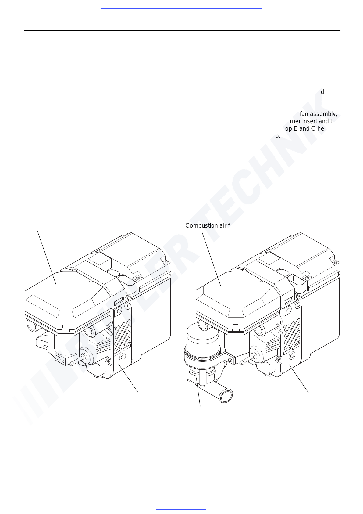
The heater consists of the combustion air fan assembly,
the control unit/heat exchanger, the burner insert and the
combustion chamber. The Thermo Top E and C heater
has an additional circulation pump.
Combustion air fan assembly
Combustion chamber
Control unit/
Thermo Top Z
heat exchanger
Control unit/
heat exchanger
Combustion air fan assembly
Combustion chamber
Circulation pump
Thermo Top E and C
Visit www.butlertechnik.com for more technical information and downloads.
www.butlertechnik.com
2 General Description Thermo Top E and Z/C
202
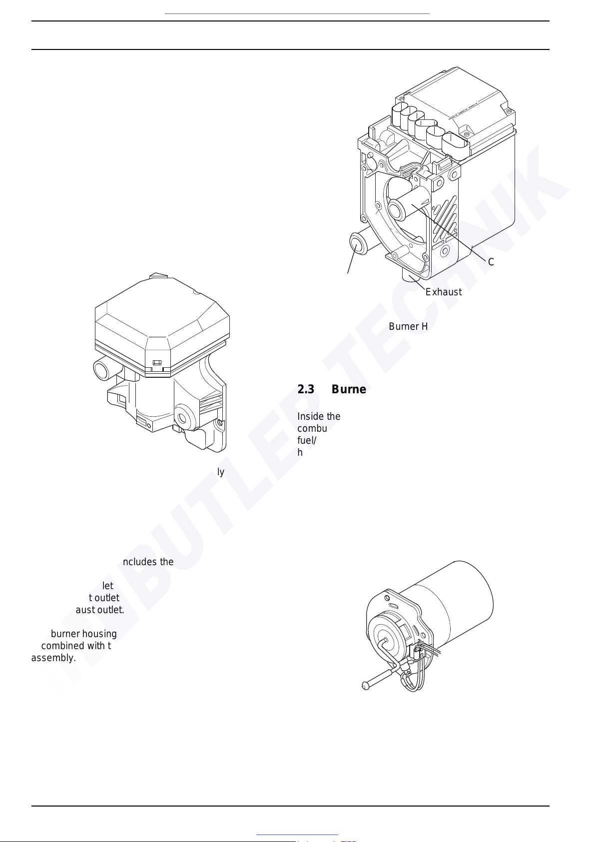
2.1 Combustion Air Fan Assembly
The combustion air fan assembly includes the
combustion air fan
combustion air line inlet
fuel supply inlet.
The heater Thermo Top E and Z has the circulation pump
mounted on the combustion air fan assembly.
2.1.1 Combustion Air Fan
The combustion air fan delivers the air required for
combustion from the combustion air inlet to the burner
insert.
Combustion Air Fan Assembly
2.2 Burner Housing
The burner housing includes the
coolant inlet
coolant outlet
exhaust outlet.
The burner housing accommodates the burner insert and
is combined with the control unit / heat exchanger to an
assembly.
Burner Housing
2.3 Burner Insert
Inside the burner insert fuel is distributed across the
combustion pipe fuel cross section. Combustion of the
fuel/air mixture takes place within the combustion pipe to
heat the heat exchanger.
The glow plug/flame sensor located in the burner insert
ignites the fuel/air mixture during start of the heater. After
start the glow plug / flame sensor operates in the flame
sensor function. The glow plug / flame sensor designed as
an electrical resistor is located in the burner insert
opposite the flame side.
Burner Insert
Coolant
Coolant
outlet
inlet
Exhaust outlet
Visit www.butlertechnik.com for more technical information and downloads.
www.butlertechnik.com
Thermo Top E and Z/C 2 General Description
203
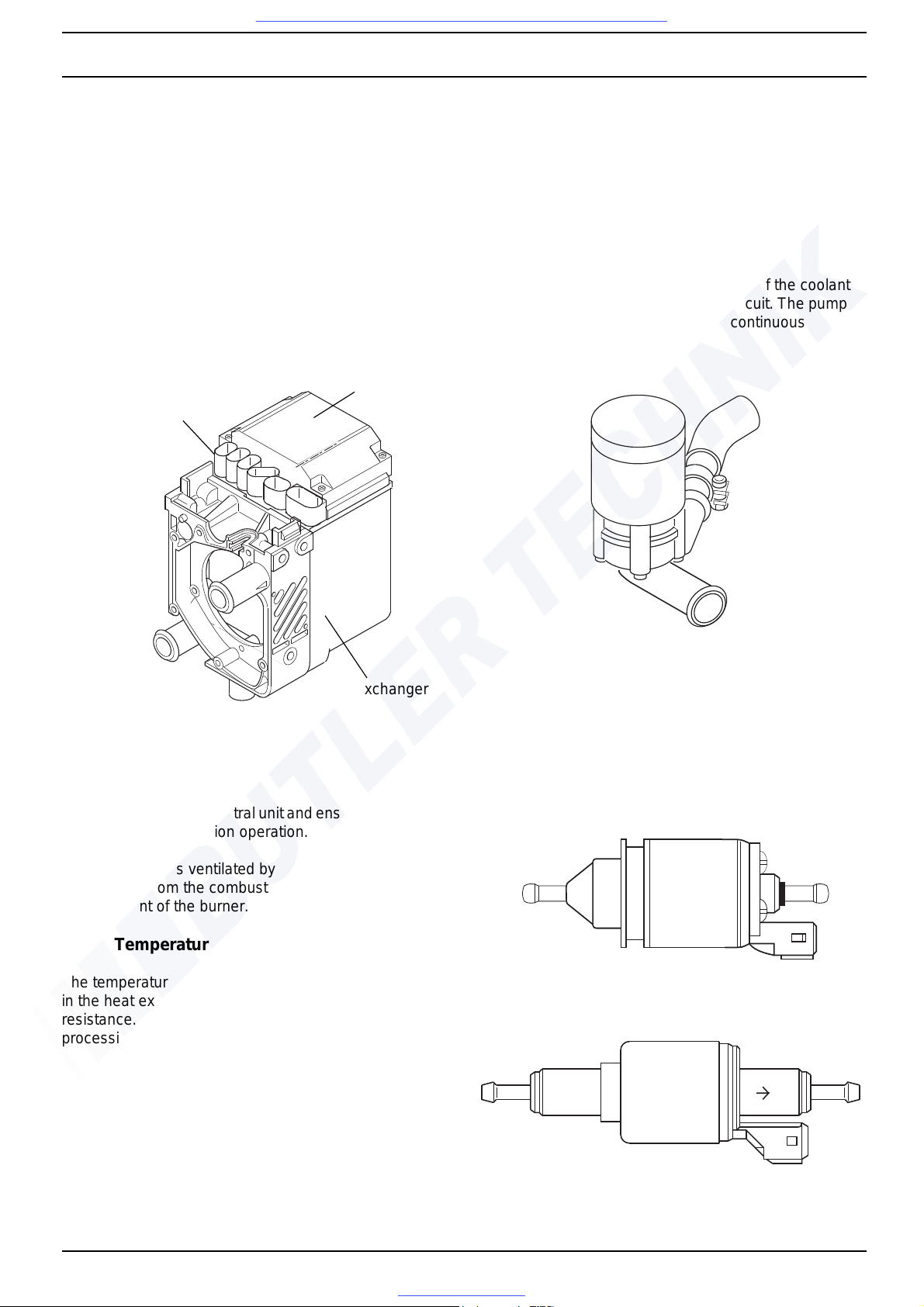
2.4 Control Unit / Heat Exchanger
The control unit / heat exchanger includes the
control unit
temperature sensor
overheat protection
heat exchanger
connector terminal.
CAUTION
The control unit / heat exchanger and the burner housing
represent an assembly and must not be disassembled.
2.4.1 Control Unit
The control unit is the central unit and ensures control and
monitoring of combustion operation.
The control unit is ventilated by means of a ventilation
hose routed from the combustion air collector
compartment of the burner.
2.4.2 Temperature Sensor
The temperature sensor senses the coolant temperature
in the heat exchanger of the heater as an electrical
resistance. This signal is routed to the control unit for
processing.
2.4.3 Overheat Protection
Overheat protection, controlled by a temperature resistor,
protects the heater against undue operating temperatures.
Overheat protection responds at a water temperature in
excess of 105° C and switches the heater off.
2.4.4 Heat Exchanger
The heat exchanger transfers the heat generated by
combustion to the coolant circuit.
2.5 Circulation Pump
(Thermo Top E and C only)
The circulation pump ensures circulation of the coolant
within the vehicle and heater coolant circuit. The pump is
activated by the control unit and is in continuous
operation.
Circulation Pump
2.6 Dosing Pump
The dosing pump is a combined delivery, dosing and
shut-off system for the fuel supply of the heater out of the
vehicle fuel tank.
Dosing Pump DP 2 for Fuel operated Heaters
Dosing Pump DP 30.2 for Diesel operated Heaters
Connector Terminal
Control Unit
Heat Exchanger
Visit www.butlertechnik.com for more technical information and downloads.
www.butlertechnik.com
2 General Description Thermo Top E and Z/C
204
Page free for notes
Visit www.butlertechnik.com for more technical information and downloads.
www.butlertechnik.com
Thermo Top E and Z/C 3 Functional Description
301
3 Functional Description
3.1 Functional Description Thermo Top Z
(Supplementary Heater)
3.1.1 Switch On / Starting
Fuel
When starting the vehicle engine the heater goes in
standby. With a water circuit temperature below 60° C and
an outside temperature below 5° C (option with outside
temperature sensor) the starting sequence commences.
The glow plug and the combustion air fan are activated.
After 30 seconds the fuel dosing pump starts operation
and combustion air fan operation is suspended for
3 seconds. Subsequently the combustion air fan speed is
increased in a ramp within 57 seconds to nearly full load
operation.
After reaching full load fuel delivery within this period the
glow plug is deactivated and the combustion air fan
operation increased to full load.
During the subsequent 45 seconds as well as in normal
operation the glow plug functions as flame sensor to
monitor the flame condition.
After all these events the automatically controlled heating
operation starts. In case of a no flame condition or a
flameout, a restart is automatically initiated. If the no flame
condition persists, fuel delivery is stopped and the heaters
enters an error lockout with a run-down of the combustion
air fan.
Diesel
When starting the vehicle engine the heater goes in
standby. With a water circuit temperature below 60° C and
an outside temperature below 5° C (option with outside
temperature sensor) the starting sequence commences.
The glow plug and the combustion air fan are activated.
After 30 seconds the fuel dosing pump starts operation
and combustion air fan operation is suspended for
3 seconds. Subsequently the combustion air fan speed is
increased in two ramps within 56 seconds to nearly full
load operation. After a stabilisation phase (constant
speed) of 15 seconds the combustion air fan speed is
again increased in a ramp within 50 seconds to nearly full
load.
After reaching full load fuel delivery the glow plug is
deactivated and the combustion air fan operation
increased to full load.
During the subsequent 45 seconds as well as in normal
operation the glow plug functions as flame sensor to
monitor the flame condition.
After all these events the automatically controlled heating
operation starts. In case of a no flame condition or a
flameout, a restart is automatically initiated. If the no flame
condition persists, fuel delivery is stopped and the heater
enters an error lockout with a run-down of the combustion
air fan.
A flameout during normal combustion operation causes
an automatic restart.
3.1.2 Heating Operation
Fuel
When the temperature rises to reach 72° C the heater
switches to the energy saving part load operation. A rise
in temperature up to 76.5° C causes the heater to enter a
control idle period. This also happens when exceeding a
total heating operating time of 76 minutes.
After cool-down of the coolant to 71° C the heater
resumes part load operation. Another rise in temperature
to 76.5° C causes the heater to enter again the control idle
period. A drop in the coolant temperature during part load
operation due to an increased demand in heat will cause
the heater to switch to full load operation at 56° C.
Diesel
Heating operation for the Diesel type heater is identical in
the sequence of events. Should the coolant temperature
drop during the control idle period to but not below 71° C
within 900 seconds, a subsequent drop in the coolant
temperature below 71° C causes the heater to perform a
regular starting sequence into full load operation.
A drop in the coolant temperature during part load
operation due to an increased demand in heat will cause
the heater to switch to full load operation at 65° C.
3.1.3 Switch Off / Deactivation
When turning the engine off the heater is deactivated.
Combustion stops and run-down commences. The
combustion air fan first continues operation to cool the
heater down (run-down) to be automatically switched off
afterwards.
NOTE
The run-down time and the combustion air fan speed
depend on the heater operating condition at the time of
deactivation.
Run-down time is for:
Fuel
168 seconds when deactivated in full load operation and
157 seconds when deactivated in part load operation.
Diesel
175 seconds when deactivated in full load operation and
100 seconds when deactivated in part load operation.
Dependent on the software variant implemented in the
control unit there might be deviations from those run-down
periods.
Visit www.butlertechnik.com for more technical information and downloads.
www.butlertechnik.com
3 Functional Description Thermo Top E and Z/C
302
3.2 Functional Description
Thermo Top E and C (Auxiliary Heater)
3.2.1 Switch On
Fuel
When operating the "instant heat" switch button the timer
display shows or when operating the switch on the
Telestart transmitter the operating indicator light on the
transmitter flashes. This puts the heater in standly.
The glow plug, the combustion air fan and the circulation
pump are activated. After 30 seconds the fuel dosing
pump starts operation and combustion air fan operation is
suspended for 3 seconds.
Subsequently the combustion air fan speed is increased
in a ramp within 57 seconds to nearly full load operation.
After reaching full load fuel delivery within this period the
glow plug is deactivated and the combustion air fan
operation increased to full load.
During the subsequent 45 seconds as well as in normal
operation the glow plug functions as flame sensor to
monitor the flame condition.
After all these events the automatically controlled heating
operation starts. In case of a no flame condition or a
flameout, a restart is automatically initiated. If the no flame
condition persists, fuel delivery is stopped and the heater
enters an error lockout with a run-down of the combustion
air fan.
Diesel
When operating the "instant heat" switch button the timer
display shows or when operating the switch on the
Telestart transmitter the operating indicator light on the
transmitter flashes. This puts the heater in standby.
The glow plug, the combustion air fan and the circulation
pump are activated. After 30 seconds the fuel dosing
pump starts operation and combustion air fan operation is
suspended for 3 seconds.
Subsequently the combustion air fan speed is increased
in two ramps within 56 seconds to nearly full load
operation. After a stabilisation phase (constant speed) of
15 seconds the combustion air fan speed is again
increased in a ramp within 50 seconds to nearly full load.
After reaching full load fuel delivery the glow plug is
deactivated and the combustion air fan operation
increased to full load.
During the subsequent 45 seconds as well as in normal
operation the glow plug functions as flame sensor to
monitor the flame condition.
After all these events the automatically controlled heating
operation starts. In case of a no flame condition or a
flameout, a restart is automatically initiated. If the no flame
condition persists, fuel delivery is stopped and the heater
enters an error lockout with a run-down of the combustion
air fan.
A flameout during normal combustion operation causes
an automatic restart.
3.2.2 Heating Operation
Fuel
When the temperature rises to reach 72° C the heater
switches to the energy saving part load operation. A rise
in temperature up to 76.5° C causes the heater to enter a
control idle period. This also happens when exceeding a
total heating operating time of 76 minutes.
The circulation pump, the vehicle's own heating air fan,
and the operation indicator light remain on during control
idle.
After cool-down of the coolant to 71° C the heater
resumes part load operation. Another rise in temperature
to 76.5° C causes the heater to enter again the control idle
period. A drop in the coolant temperature during part load
operation due to an increased demand in heat will cause
the heater to switch to full load operation at 56° C.
Diesel
Heating operation for the Diesel type heater is identical in
the sequence of events. Should the coolant temperature
however not drop within 900 seconds during the control
idle period to below 71° C, a subsequent drop in the
coolant temperature below 71° C causes the heater to
perform a regular starting sequence into full load
operation.
3.2.3 Switch Off
When turning the heater off by pushing the "instant heat"
switch button ( in indicator panel extinguishes) or
when operating the switch on the Telestart (flashing
indicator on hand-held transmitter extinguishes) the
vehicle heating air fan stops.
Combustion terminates and run-down commences. The
circulation pump and the combustion air fan first continue
operation to cool the heater down (run-down) to be
automatically switched off afterwards.
NOTE
The run-down time and the combustion air fan speed
depend on the heater operating condition at the time of
deactivation.
Run-down time is for:
Fuel
168 seconds when deactivated in full load operation and
157 seconds when deactivated in part load operation.
Diesel
175 seconds when deactivated in full load operation and
100 seconds when deactivated in part load operation.
Dependent on the software variant implemented in the
control unit there might be deviations from those run-down
periods.
Visit www.butlertechnik.com for more technical information and downloads.
www.butlertechnik.com
Thermo Top E and Z/C 3 Functional Description
303
3.2.4 Auxiliary Heater in Supplementary Heater
Function
3.2.4.1 Switch On
When starting the engine the heater goes in standby
(see 3.1.1).
With the temperature of the water circuit below 60° C and
the outside temperature below 5° C (option with external
temperature sensor) the starting procedure is initiated.
NOTE
When operating in the supplementary heater function
there will be no automatic trigger of the circulation pump
and the vehicle's heating air fan.
3.2.4.2 Switch Off
Turning the engine off deactivates the heater.
Combustion is terminated and run-down commences.
The combustion air fan however continues operation to
cool the heater down (run-down) to be automatically
switched off afterwards (see 3.1.3).
Visit www.butlertechnik.com for more technical information and downloads.
www.butlertechnik.com
 Loading...