

Page 1
Stand for Webasto charging station
TR
TR
TR
TR
TR
TR
TR
SV
Webasto Charging Solutions
Installation Instructions ......................................3
Installationsanweisung .......................................6
Montagehandleiding ..........................................9
Monteringsvejledning ........................................12
Asennusohjeet ...................................................15
Notice de montage ............................................18
Monteringsanvisning ..........................................21
Monteringsanvisning ..........................................24
Page 2
3
1
2
120
4
5
6
250
170
74
83
346
288
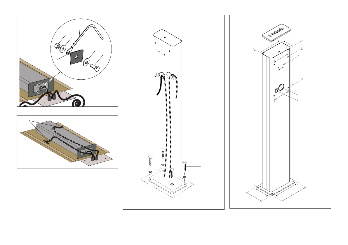
Fig. 01:
1
Fig. 02:
Ground connection
Cable feed through
Fig. 03:
Final mounting
174
Ø 60,5
Ø 33,1
1493
1
2
260
300
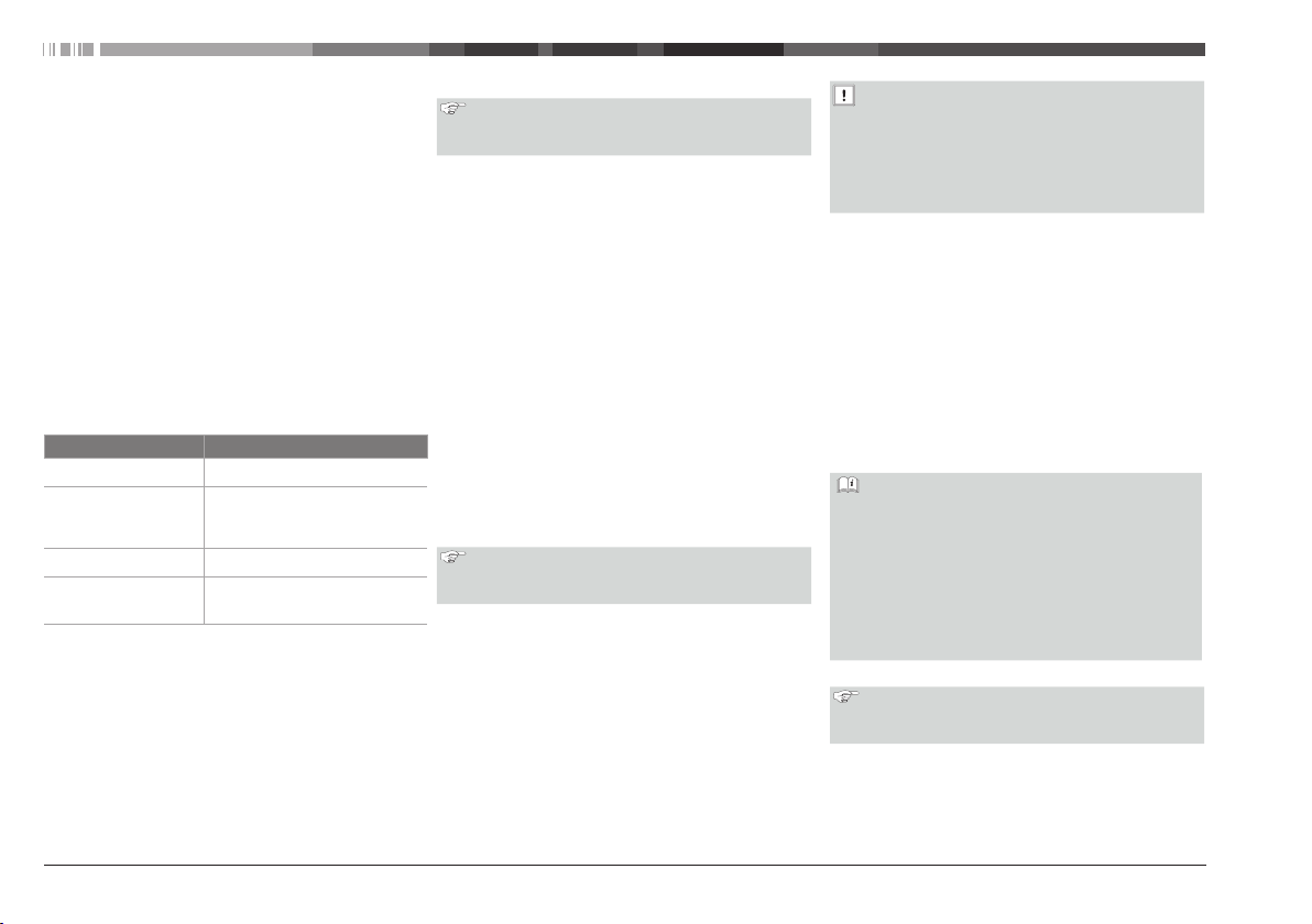
Fig. 04:
150
190
Stand dimensions
Page 3

1 About this document
1.1 Purpose of the document
These Installation Instructions are part of the product and
contain all the information required to ensure correct and
safe installation.
1.2 Using this document
Read these Installation Instructions before installing the
stand.
Read the Webasto Pure or Live Operating and
Installation Instructions before installing the stand.
Keep these Installation Instructions at hand.
Hand these Installation Instructions over to the next
user/owner.
1.3 Use of symbols and highlighting
DANGER: This signal word denotes a hazard with a
high degree of risk which, if not avoided, will lead to
death or serious injury.
WARNING: This signal word denotes a hazard with
a moderate degree of risk which, if not avoided, may
lead to minor or moderate injury.
CAUTION: This signal word denotes a hazard with a
low degree of risk which, if not avoided, may lead to
minor or moderate injury.
NOTE: This signal word denotes a Special Technical
Feature or (if not observed) potential damage to the
product.
Texts with this symbol refer to separate documents
which are enclosed or can be requested from
Webasto.
Text with this symbol describes an action or requirement for the following necessary action.
Text with this symbol describes a necessary action.
Stand Wallbox 3
1.4 Warranty and liability
Webasto shall not assume liability for defects or damage
that are the result that the installation and operating
instructions as well as the instructions contained therein
being disregarded.
This liability exclusion particularly applies for:
■■
installation by untrained personnel
■■
improper use
■■
repairs not carried out by a Webasto service workshop
■■
use of non-genuine parts
■■
conversion of the unit without permission from Webasto
2 Safety
2.1 Intended use
The stand is intended for the mounting of Webasto Pure
and/or Live charging stations in a free space, independent
of wall mounting.
It is not allowed to mount other than Webasto Pure or Live
charging stations.
There are 2 product variations:
1 Mounting of a single Webasto Pure or Live charging
station.
2 Mounting of two Webasto Pure or Live charging sta-
tions.
CAUTION
In case of variation 2 it is not allowed to mount only
one charging station and leave the other position
open.
NOTE
These Installation Instructions consider the installation
of a Variation 2 stand for Webasto Pure charging
stations.
2.2 Qualifications of installation personnel
These installation instructions are meant for certified
and qualified installation personnel with a corresponding qualification for working on electrotechnical systems.
2.3 General safety information
The stand for the Webasto Pure or Live charging stations
has been developed, produced, tested and documented
according to the relevant safety and environmental requirements and regulations. The device must only be used in a
technically faultless condition.
Have any faults that adversely affect the safety of persons
or of the device rectified immediately by an authorised electrician in accordance with nationally applicable regulations.
WARNING
Hazardous voltages
Severe or mortal injury
Take all the necessary standard precautions for
working on electrical systems.
CAUTION
Hazard of electric shock, explosion or arc flash
Severe injury or damage to the equipment
Take care of an adequate ground connection of
the stand that fulfils the local regulations.
NOTE
Always obey local regulations for electrical installations.
Ensure only persons who have read these Installation
Instructions have access to the stand.
3 Scope of Delivery
The Scope of Delivery consists of:
■■
Stand
■■
Click-on cover
■■
Installation kit, consisting of:
– Screw TX M6 x 25 (2 or 4)
– Screw TX M6 x 50 (2 or 4)
– Screw M8x20
Page 4
– Nut M8
– Washer M8
– Spring washer M8
■■
Installation Instructions
Check the Scope of delivery on completeness and
damage.
– Do not install a damaged stand.
– Notify Webasto Customer Service in case of damage.
4 Installation
Observe the safety information provided in chapter 2.
In addition to these installation instructions follow and
comply with the local regulations relating to operation,
installation and environmental protection.
Install the stand only in combination with the application of the Operating- and Installation instructions of the
Webasto Pure or Live charging stations
4.1 Required tools
Tool Description
Torx screwdriver TX30 Mounting of the charging stations
Check resistance of the ground
Earth ground tester
Cabling tools Making the ground connection.
General tools, drills,
drilling machine.
4.2 Location requirements
General
The intended location must fulfil all the requirements
3
mentioned in the Webasto Pure or Live Operating- and
Installation instructions.
In case the stand is installed close to a road or on a pub-
3
lic parking place, open or roofed, an adequate collision
guard / protector must be installed.
In case more than 1 stand will be installed next to each
3
other, the free space between two stands should be at
connection.
Verify cables are potential-free.
Mounting of the ground connection and mounting of the stand.
The surface must be fully flat.
3
NOTE:
Do not install the stand on asphalt. The stability of
the stand on asphalt is not guaranteed.
4.3 Concrete base
■■
For a secure installation of the stand a concrete base is
recommended:
– The calculations, design and creation of the base are the
responsibility of the manufacturer of the concrete base.
– Water should not be collected at the base but should be
drained naturally.
■■
The electrical supply cables must come out of the
concrete at the centre of the base and have an excess
length of at least 1500mm.
■■
The manufacturer of the base must take care of
adequate protection of the cables. Protections sleeves
should extend to at least 250mm above the concrete.
■■
A ground connection should be available.
– If a ground connection is not implemented, an earth
point can be made with help of an earth rod. In such
a case the earth rod should be positioned in the
centre of the base of the stand.
4.4 Installation of the stand on a concrete base
NOTE:
Dowels, screws and washers for mounting the stand
to the concrete are not part of the Scope of Delivery.
Position the stand over the cables. Make sure the cables
are in the centre of the stand.
Mark the position of the bore-holes on the concrete.
Remove the stand.
Drill the holes for dowels.
Insert the dowels in the bore holes. Make sure they are
level with the concrete.
The Webasto charging stations safety concept is
based on a power supply system that is grounded at
all times. The authorised electrician must ensure this
requirement during installation.
Do not install the stand if there is no ground
connection or a ground connection that does not
fulfils the requirements.
Provide a suitable cable lug M8 (Fig. 01; 6) to the
ground wire (Fig. 01; 3).
Connect the ground wire to the stud in the stand
housing with the M8 screw, spring washer, washer and
nut (Fig. 01; 1, 2, 4, 5) from the Scope of Delivery.
Make sure the ground connection fulfils the local
requirements for ground connections. Make sure the
resistance is lower than 0.1Ω.
Thread the electrical cables (Fig. 02; 1), from the bottom
side up, through their respective feed-throughs.
Put the stand in the upright position.
Mount the stand with washers (Fig. 03; 2) and screws
(Fig. 03; 1).
Mount the Webasto Pure or Live charging
stations according the Webasto Pure or Live
Operating and Installation Instructions.
Use the washers of the Scope of Delivery of the
charging stations but use the screws of the Scope
of Delivery of the stand.
Use TX M6 x 25 screws for the top part of the
charging station.
Use TX M6 x 50 screws for the bottom part of the
charging station.
Install the cover on the stand by clipping it onto it.
NOTE:
Once the cover is installed,it is fixed on the stand and
cannot be removed again.
5 Maintenance, cleaning and repair
5.1 Maintenance
The stand does not require any maintenance.
least 200mm.
4 Stand Wallbox
Page 5
5.2 Cleaning
DANGER
High voltages
Danger of fatal electric shock
Never clean the stand with a high-pressure cleaner or
similar device.
Clean the installation only with a dry cloth. Do not use
aggressive cleaning agents, wax or solvents.
NOTE:
■■
Do not use alkaline cleaning agents. Alkaline
cleaning agents cause a colouring of the stand.
■■
Tree resin also could cause colouring of the stand.
5.3 Repair
Unauthorised repair of the stand is not permitted.
Webasto Thermo & Comfort SE reserves the exclusive right
to perform repairs on the stand.
6 Decommissioning the stand
In case the stand is to be decommissioned an authorised
electrician should decommission the installation.
Decommission the charging station(s) according the
Operating and Installation Instructions of the charging
stations.
Dismantle the stand.
Dispose off the stand in accordance with national
regulations.
7 Disposal
Dispose of packaging in a corresponding recycling
container in accordance with the national regulations.
8 Annex
8.1 Technical data
Dimensions [mm] See Fig. 04
Weight [kg] 18.2
Material Steel
Corrosion protection
Data
Electrophoretic- and powder coated
Stand Wallbox 5
Page 6
1 Zu diesem Dokument
1.1 Zweck des Dokuments
Diese Einbauanweisung ist Teil des Produkts und enthält alle
Informationen zum korrekten und sicheren Einbau.
1.2 Umgang mit diesem Dokument
Vor der Installation des Standfußes die vorliegende
Einbauanweisung durchlesen.
Vor der Installation des Standfußes die Webasto Pure
bzw. Live Bedienungs- und Einbauanweisung durchlesen.
Diese Einbauanweisung zum Nachlesen aufbewahren.
Diese Einbauanweisung an nachfolgende Benutzer/
Besitzer weitergeben.
1.3 Verwendung von Symbolen und
Hervorhebungen
GEFAHR: Das Signalwort bezeichnet eine Gefähr-
dung mit einem hohen Risikograd, die, wenn sie
nicht vermieden wird, den Tod oder eine schwere
Verletzung zur Folge hat.
WARNUNG: Das Signalwort bezeichnet eine Gefährdung mit einem mittleren Risikograd, die, wenn sie
nicht vermieden wird, eine geringfügige oder mäßige
Verletzung zur Folge haben kann.
VORSICHT: Das Signalwort bezeichnet eine Gefährdung mit einem niedrigen Risikograd, die, wenn sie
nicht vermieden wird, eine geringfügige oder mäßige
Verletzung zur Folge haben kann.
HINWEIS: Das Signalwort bezeichnet eine Technische Besonderheit oder (bei Nichtbeachtung) einen
möglichen Schaden am Produkt.
Texte mit diesem Symbol verweisen auf separate
Dokumente, die beigelegt sind oder bei Webasto
angefordert werden können.
Texte mit diesem Symbol beschreiben eine Handlung
oder Voraussetzung für die folgende Handlungsanweisung.
Texte mit diesem Symbol beschreiben eine Handlungsanweisung.
6 Stand Wallbox
1.4 Gewährleistung und Haftung
Webasto übernimmt keine Haftung für Mängel und
Schäden, die darauf zurückzuführen sind, dass Einbau- und
Bedienungsanweisung sowie darin enthaltene Hinweise
nicht beachtet wurden.
Dieser Haftungsausschluss gilt insbesondere für:
■■
Einbau durch ungeschultes Personal
■■
Unsachgemäße Verwendung
■■
Nicht von einer Webasto Service-Werkstatt ausgeführte
Reparaturen
■■
Verwendung von Nicht-Originalersatzteilen
■■
Umbau des Geräts ohne Zustimmung von Webasto
2 Sicherheit
2.1 Bestimmungsgemäße Verwendung
Der Standfuß dient zur Aufnahme von Webasto Pure und/
oder Live Ladestationen auf einer freien Fläche, wo eine
Wandmontage nicht möglich ist.
Es dürfen nur Webasto Pure oder Live Ladestationen
montiert werden.
Es gibt 2 Produktvarianten:
1 Aufnahme eines Webasto Pure oder Live Ladestationen.
2 Aufnahme von zwei Webasto Pure oder Live Ladesta-
tionen.
VORSICHT
Bei Variante 2 ist es nicht zulässig, nur eine Ladestation zu montieren und den anderen Platz leer zu
lassen.
HINWEIS
Diese Einbauanweisung bezieht sich auf die Installation eines Standfuß der Variante 2 für Webasto Pure
Ladestationen.
2.2 Qualifikation des Einbaupersonals
Diese Einbauanweisung ist für zertifiziertes und
qualifiziertes Einbaupersonal mit entsprechender
Qualifikation für Arbeiten an elektrotechnischen
Systemen bestimmt.
2.3 Allgemeine Sicherheitshinweise
Der Standfuß für Webasto Pure bzw. Live Ladestationen
wurde gemäß den relevanten Sicherheits- und Umweltvorschriften und -bestimmungen entwickelt, hergestellt,
geprüft und dokumentiert. Das Gerät nur in technisch
einwandfreiem Zustand verwenden.
Störungen, die die Sicherheit von Personen oder des Geräts
beeinträchtigen, sofort von einer autorisierten Elektrofachkraft nach den national geltenden Regeln beheben zu
lassen.
WARNUNG
Gefährlich hohe Spannungen
Schwere oder tödliche Verletzung
Alle erforderlichen Vorsichtsmaßnahmen für das
Arbeiten an elektrischen Systemen ergreifen.
VORSICHT
Gefahr von Stromschlag, Explosion oder Lichtbogenüberschlag
Schwere Verletzung oder Beschädigung des
Geräts
Für angemessene Erdung des Standfuß
entsprechend den örtlich geltenden Vorschriften
sorgen.
HINWEIS
Stets die örtlich geltenden Vorschriften für Elektroinstallationen beachten.
Sicherstellen, dass nur Personen, die diese Einbauanweisung gelesen haben,
Zugang zum Standfuß erhalten.
3 Lieferumfang
Der Lieferumfang umfasst:
■■
Standfuß
Page 7
■■
Abdeckung
■■
Einbaukit, bestehend aus:
– Schraube TX M6x25 (2 bzw. 4)
– Schraube TX M6x50 (2 bzw. 4)
– Schraube M8x20
– Mutter M8
– Unterlegscheibe M8
– Federring M8
■■
Installationsanweisung
Lieferung auf Vollständigkeit und Schäden kontrollieren.
– Bei Schäden den Standfuß nicht installieren.
– Den Webasto Kundendienst über den Schaden
informieren.
4 Installation
Die Sicherheitshinweise in Kapitel 2 beachten.
Neben diesen Installationsanweisungen auch die lokalen
Bestimmungen in Bezug auf Betrieb, Installation und Umwelt folgen und einhalten.
Zur Installation des Standfuß zusätzlich die Bedienungs- und
Einbauanweisung der Webasto Pure bzw. Live Ladestationen beachten.
4.1 Erforderliche Werkzeuge
Werkzeug Beschreibung
Torx-Schraubendreher
TX30
Erdungsprüfer
Verkabelungswerkzeuge
Allgemeine Werkzeuge, Bohrer, Bohrmaschine.
Montage der Ladestationen
Überprüfung des Widerstands des
Erdungsanschlusses.
Überprüfen, dass Kabel potentialfrei sind.
Herstellen des Erdungsanschlusses.
Montage des Erdungsanschlusses
und Montage des Standfußes.
4.2 Anforderungen an den Einbauort
Allgemein
Der Einbauort muss alle Anforderungen erfüllen, die in
3
der Webasto Pure bzw. Live Bedienungs- und Einbauanweisung aufgeführt sind.
Bei Installation des Standfußes an einer Straße oder
3
einem öffentlichen Parkplatz, offen oder überdacht,
muss ein entsprechender Anfahr-/Rammschutz angebaut
werden.
Sollen mehrere Standfüße nebeneinander installiert
3
werden, muss der Abstand zwischen den einzelnen
Standfüßen mind. 200mm betragen.
Die Oberfläche muss vollständig plan sein.
3
HINWEIS:
Den Standfuß nicht auf Asphalt installieren. Auf
Asphalt ist die Standsicherheit des Standfuß nicht
gewährleistet.
4.3 Betonsockel
■■
Zur sicheren Installation des Standfußes wird ein Betonsockel empfohlen:
– Auslegung, Konstruktion und Ausführung des Sockels
sind Aufgabe des Herstellers des Betonsockels.
– Es darf sich kein Wasser am Sockel ansammeln, dieses
muss natürlich abfließen.
■■
Die Stromversorgungskabel müssen in der Mitte des
Betonsockels austreten und eine überstehende Länge
von mind. 1500mm haben.
■■
Der Sockelhersteller muss für ausreichenden Schutz der
Kabel sorgen. Schutzhüllen müssen mind. 250mm aus
dem Beton herausreichen.
■■
Ein Erdungsanschluss sollte vorhanden sein.
– Ist kein Erdungsanschluss vorhanden, kann mit einem
Erdungsstab ein Erdungspunkt hergestellt werden. In
diesem Fall muss sich der Erdungsstab in der Mitte des
Sockels des Standfuß befinden.
4.4 Installation des Standfuß auf einem Betonsockel
HINWEIS:
Dübel, Schrauben und Unterlegscheiben zur Montage
des Standfußes am Betonsockel sind nicht im Lieferumfang enthalten.
Den Standfuß über den Kabeln positionieren.
Sicherstellen, dass sich die Kabel mittig unter dem
Standfuß befinden.
Die Position der Bohrlöcher auf dem Betonsockel
markieren.
Den Standfuß entfernen.
Die Löcher für die Dübel bohren.
Die Dübel in die Bohrlöcher einsetzen. Darauf achten,
dass sie bündig mit der Betonoberfläche abschließen.
Das Sicherheitskonzept der Webasto Ladestationen
basiert auf einer jederzeit und durchgängig geerdeten
Netzform. Die autorisierte Elektrofachkraft hat dies
bei der Installation sicher zu stellen.
Den Standfuß nicht installieren, wenn es keinen
Erdungsanschluss gibt oder der vorhandene
Erdungsanschluss nicht den Anforderungen
entspricht.
Einen geeigneten M8-Kabelschuh (Fig. 01; 6) an der
Erdungsleitung anbringen (Fig. 01; 3).
Die Erdungsleitung mit M8-Schraube, Federring,
Unterlegscheibe und Mutter (Fig. 01; 1, 2, 4, 5) aus dem
Lieferumfang am Erdungspunkt des Standfußgehäuses
anschließen.
Sicherstellen, dass der Erdungsanschluss die örtlich
geltenden Vorschriften für Erdungsanschlüsse erfüllt.
Überprüfen, dass der Widerstand unter 0,1Ω liegt.
Die Elektrokabel (Fig. 02; 1) von unten nach oben durch
die entsprechenden Durchführungen führen.
Den Standfuß aufrichten.
Den Standfuß mit Unterlegscheiben (Fig. 03; 2) und
Schrauben (Fig. 03; 1) montieren.
Stand Wallbox 7
Page 8
Die Webasto Pure bzw. Live Ladestationen
entsprechend Webasto Pure bzw. Live
Bedienungs- und Einbauanweisung montieren.
Dazu die Unterlegscheiben aus dem Lieferumfang
der Ladestationen und die Schrauben aus dem
Lieferumfang des Standfuß verwenden.
Für den oberen Teil der Ladestation TX-Schrauben
der Größe M6x25 verwenden.
Für das untere Teil der Ladestation TX-Schrauben
der Größe M6x50 verwenden.
Die Abdeckung oben auf den Standfuß aufstecken.
HINWEIS:
Wenn die Abdeckung aufgesteckt und eingerastet ist,
kann sie nicht wieder entfernt werden.
5 Wartung, Reinigung und Reparatur
5.1 Wartung
Eine Wartung des Standfußes ist nicht nötig.
5.2 Reinigung
GEFAHR
Hohe Spannungen
Gefahr von tödlichen elektrischen Stromschlä-
gen
Den Standfuß niemals mit einem Hochdruckreiniger
oder einem ähnlichen Gerät reinigen.
Anlage nur mit einem Tuch trocken abwischen. Keine
aggressiven Reinigungsmittel, Wachs oder Lösungsmittel
verwenden.
HINWEIS:
■■
Keine alkalischen Reinigungsmittel verwenden.
Alkalische Reinigungsmittel verursachen Verfärbungen am Standfuß.
■■
Auch Baumharze können Verfärbungen am Standfuß verursachen.
5.3 Reparatur
Die eigenmächtige Reparatur des Standfuß ist untersagt.
Webasto Thermo & Comfort SE behält sich das ausschließ-
liche Recht vor, Reparaturen am Standfuß durchzuführen.
6 Außerbetriebnahme des Standfuß
Wenn der Standfuß außer Betrieb genommen werden
muss, so muss dies durch eine autorisierte Elektrofachkraft
erfolgen.
Die Ladestationen entsprechend Bedienungs- und
Einbauanweisung außer Betrieb nehmen.
Den Standfuß demontieren.
Den Standfuß gemäß den geltenden nationalen
Vorschriften entsorgen.
7 Entsorgung
Verpackungen gemäß den geltenden nationalen
Vorschriften in einem entsprechenden Recyclingbehälter
entsorgen.
8 Anhang
8.1 Technische Daten
Abmessungen [mm] Siehe Fig. 04
Gewicht [kg] 18,2
Material Stahl
Korrosionsschutz
Data
Elektrophoretisch und
pulverbeschichtet
8 Stand Wallbox
Page 9
1 Over dit document
1.1 Doel van het document
Deze montagehandleiding is een onderdeel van het product en omvat alle informatie die nodig is voor correcte en
veilige montage.
1.2 Dit document gebruiken
Lees deze montagehandleiding voordat u de standaard
monteert.
Lees de bedienings- en montagehandleiding van de
Webasto Pure of Live voordat u de standaard monteert.
Houd deze montagehandleiding bij de hand.
Geef de montagehandleiding aan de volgende
gebruiker/eigenaar.
1.3 Gebruik van symbolen en accentuering
Gevaar: Dit signaalwoord geeft een gevaar aan met,
indien niet vermeden, een groot risico op de dood of
ernstig letsel.
WAARSCHUWING: Dit signaalwoord geeft een gevaar aan met, indien niet vermeden, een gemiddeld
risico op licht of gemiddeld letsel.
VOORZICHTIG: Dit signaalwoord geeft een gevaar
aan met, indien niet vermeden, een laag risico op
licht of gemiddeld letsel.
Aanwijzing: Dit signaalwoord geeft een speciale
technische functie of (indien niet vermeden) mogelijk
schade aan het product aan.
Tekst met dit symbool verwijst naar aparte documenten die zijn meegeleverd of die kunnen worden
opgevraagd bij Webasto.
Tekst met dit symbool verwijst naar een actie of
vereiste voor de volgende handeling.
Tekst met dit symbool verwijst naar een handeling die
moet worden uitgevoerd.
Stand Wallbox 9
1.4 Garantie en aansprakelijkheid
Webasto is niet aansprakelijk voor gebreken of schade
die terug te leiden zijn naar de niet-inachtneming van de
instructies in de montage- en bedieningshandleiding.
Deze aansprakelijkheidsuitsluiting geldt in het bijzonder
voor:
■■
Montage door ongeschoold personeel
■■
Ondeskundig gebruik
■■
Reparaties die niet uitgevoerd zijn door een Webasto
Servicewerkplaats
■■
Gebruik van niet-originele onderdelen
■■
Verbouwing van het apparaat zonder toestemming van
Webasto
2 Veiligheid
2.1 Beoogd gebruik
De standaard is bedoeld voor de bevestiging van
Webasto Pure- en/of Live-laadstations in een vrije ruimte,
onafhankelijk of aan de muur gemonteerd.
Alleen Webasto Pure- of Live-laadstations mogen worden
gemonteerd.
Er zijn twee productversies:
1 Montage van één Webasto Pure- of Live-laadstation.
2 Montage van twee Webasto Pure- of Live-laadstations.
VOORZICHTIG
Bij versie 2 is het niet toegestaan één laadstation te
monteren en de andere positie open te laten.
AANWIJZING
Deze montagehandleiding gaat uit van de montage
van een versie 2-standaard van Webasto Pure-laadstations.
2.2 Kwalificaties montagepersoneel
Deze montagehandleiding is bedoeld voor gecertificeerd en gekwalificeerd montagepersoneel met een
overeenkomende kwalificatie voor het werken aan
elektrotechnische systemen.
2.3 Algemene veiligheidsinformatie
De standaard voor de Webasto Pure- of Live-laadstations
is ontwikkeld, geproduceerd, getest en gedocumenteerd
overeenkomstig de relevante vereisten en regelgeving
voor veiligheid en milieu. Het apparaat mag alleen worden
gebruikt indien het in foutloze staat is.
Storingen die een negatieve impact kunnen hebben op de
veiligheid van personen of het apparaat, moeten meteen
worden verholpen door een geautoriseerde elektricien
overeenkomstig nationale regelgeving.
WAARSCHUWING
Gevaarlijke spanning
Ernstige of dodelijke verwondingen
Neem alle vereiste standaard voorzorgsmaatregelen voor werken met elektrische
systemen.
VOORZICHTIG
Gevaar voor elektrische schokken, explosie of
vonkoverslag
Ernstig letsel of schade aan de apparatuur
Zorg voor een goede aardverbinding van
de standaard die voldoet aan de plaatselijke
regelgeving.
AANWIJZING
Houd u altijd aan plaatselijke regelgeving voor elektrische installaties.
Alleen mensen die deze montagehandleiding
hebben gelezen, mogen werken met de standaard.
3 Leveromvang
De levering bestaat uit:
■■
Standaard
■■
Afdekking die kan worden vastgeklikt
■■
Montagekit, bestaand uit:
– Schroef TX M6 x 25 (2 of 4)
– Schroef TX M6 x 50 (2 of 4)
– Schroef M8x20
– Moer M8
– Ring M8
– Veerring M8
■■
Montagehandleiding
Page 10

Controleer of de levering compleet en schadevrij is.
– Monteer geen beschadigde standaard.
– Breng de klantenservice van Webasto op de hoogte in
het geval van schade.
4 Montage
Volg de veiligheidsinformatie in hoofdstuk 2 op.
Naast deze montagehandleiding moet u de plaatselijke re-
gelgeving opvolgen met betrekking tot bediening, montage
en bescherming van het milieu.
Monteer de standaard alleen in combinatie met de bedienings- en montagehandleiding voor de Webasto Pure- of
Live-laadstations.
4.1 Benodigd gereedschap
Gereedschap Beschrijving
Torx-schroevendraaier
TX30
Aardingtester
Kabelgereedschap De aardverbinding maken.
Algemeen gereedschap, boren, boormachine.
4.2 Locatievereisten
Algemeen
De beoogde locatie moet voldoen aan de vereis-
3
ten in bedienings- en montagehandleiding van de
Webasto Pure of Live.
Als de standaard in de buurt van een weg of op een
3
openbare parkeerplaats (overdekt of onoverdekt) wordt
gemonteerd, moet er een geschikte botsbescherming
worden geplaatst.
Als er meerdere standaarden naast elkaar worden
3
gemonteerd, moet de ruimte tussen twee standaarden
ten minste 200mm zijn.
De laadstations monteren
Controleer de weerstand van de
aardverbinding.
Controleer of de kabels potentiaalvrij zijn.
Montage van de aardverbinding
en montage van de standaard.
Het oppervlak moet vlak zijn.
3
AANWIJZING:
Monteer de standaard niet op asfalt. De stabiliteit van
de standaard op asfalt is niet gegarandeerd.
4.3 Betonnen basis
■■
Voor veilige montage van de standaard wordt een
betonnen basis aangeraden:
– De berekeningen, het ontwerp en de productie van de
basis zijn de verantwoordelijkheid van de producent van
de betonnen basis.
– Er mag zich geen water ophopen in de basis. Water
moet op een natuurlijke manier worden afgevoerd.
■■
De elektrische voedingskabels moeten in het midden van
de basis uit het beton steken en een speling hebben van
ten minste 1500mm.
■■
De fabrikant van de basis moet zorgen voor goede bescherming van de kabels. Beschermende moffen moeten
ten minste 250mm boven het beton uitsteken.
■■
Er moet een aardverbinding zijn.
– Als er geen aardverbinding is, kan er een aardpunt
worden gemaakt met een aardstaaf. In dergelijke
gevallen moet er een aardstaaf in het midden van de
basis van de standaard worden geplaatst.
4.4 Montage van de standaard op een betonnen
basis
AANWIJZING:
Deuvels, schroeven en ringen voor montage van de
standaard aan het beton zijn geen onderdeel van de
leveromvang.
Plaats de standaard over de kabels. Zorg ervoor dat de
kabels zich in het midden van de standaard bevinden.
Markeer de positie van de boorgaten op het beton.
Verwijder de standaard.
Boor de gaten voor de deuvels.
Steek de deuvels in de boorgaten. Zorg ervoor dat ze op
gelijke hoogte zijn met het beton.
Het veiligheidsconcept voor laadstations van Webasto
is gebaseerd op een voedingssysteem dat altijd geaard is. De geautoriseerde elektricien moet aan deze
vereisten voldoen tijdens montage.
Monteer de standaard niet als er geen
aardverbinding is of als de aardverbinding niet
voldoet aan de vereisten.
Plaats een geschikte kabelschoen M8 (Fig. 01; 6) op de
aardleiding (Fig. 01;3).
Verbind de aardleiding met de nop in de behuizing van
de standaard met behulp van de M8-schroef, veerring,
ring en moer (Fig. 01; 1, 2, 4, 5) uit de leveromvang.
Zorg ervoor dat de aardverbinding voldoet aan de
plaatselijke vereisten voor aardverbindingen. De
weerstand moet lager zijn dan 0,1Ω.
Leid de elektrische kabels (Fig. 02; 1) vanaf de onderzijde
door de respectieve doorgangen.
Plaats de standaard rechtop.
Monteer de standaard met behulp van ringen (Fig. 03;
2) en schroeven (Fig. 03; 1).
Monteer de Webasto Pure- of Live-laadstations
volgens de bedienings- en montagehandleiding
van Webasto Pure of Live.
Gebruik de ringen uit de leveromvang voor de
laadstations, maar gebruik de schroeven van de
leveromvang voor de standaard.
Gebruik TX M6 x 25 schroeven voor de bovenzijde
van het laadstation.
Gebruik TX M6 x 50 schroeven voor de onderzijde
van het laadstation.
Plaats de afdekking op de standaard door deze erop te
klikken.
AANWIJZING:
Zodra de kap is geplaatst, is deze aan de standaard
bevestigd en kan dan niet meer worden verwijderd.
5 Onderhoud, reiniging en reparatie
5.1 Onderhoud
De standaard vereist geen onderhoud.
10 Stand Wallbox
Page 11

5.2 Reinigen
GEVAAR
Hoge spanning
Gevaar van elektrische schokken
Reinig de standaard nooit met een hogedrukreiniger
of een apparaat dat daar op lijkt.
Reinig de installatie met een droge doek. Gebruik geen
agressieve reinigingsmiddelen, was of oplosmiddelen.
AANWIJZING:
■■
Gebruik geen alkalische reinigingsmiddelen. Alkalische reinigingsmiddelen veroorzaken verkleuring
van de standaard.
■■
Boomhars kan ook verkleuring van de standaard
veroorzaken.
5.3 Reparatie
Ongeautoriseerde reparatie van de standaard is niet
toegestaan.
Webasto Thermo & Comfort SE behoudt zich het exclusieve
recht voor reparaties uit te voeren aan de standaard.
6 De standaard ontmantelen
In het geval dat de standaard moet worden ontmanteld,
moet dit worden uitgevoerd door een geautoriseerde
elektricien.
Ontmantel het laadstation overeenkomstig de
bedienings- en montagehandleiding van het laadstation.
Demonteer de standaard.
Gooi de standaard weg overeenkomstig de nationale
regelgeving.
7 Verwijdering
Gooi de verpakking weg in een geschikte recyclingcontainer overeenkomstig de nationale regelgeving.
8 Bijlage
8.1 Technische gegevens
Afmetingen [mm] Zie Fig. 04
Gewicht [kg] 18,2
Materiaal Staal
Corrosiebescherming
Gegevens
Elektroforetisch en poedercoating
Stand Wallbox 11
Page 12

1 Om dette dokument
1.1 Dokumentets formål
Monteringsvejledningen er del af produktet og indeholder
alle nødvendige informationer der sikrer en korrekt og
sikker montering.
1.2 Brug af dette dokument
Læs monteringsvejledningen inden standeren monteres.
Læs Webasto Pure eller Live drifts- og
monteringsvejledninger inden standeren installeres.
Hav altid denne monteringsvejledning ved hånden.
Overdrag denne monteringsvejledning til den næste
bruger/ejer.
1.3 Anvendelse af symboler og fremhævelser
FARE: Dette signal henviser til en fare med en høj
risiko, der vil medføre død eller alvorlige personskader, såfremt det ikke overholdes.
ADVARSEL: Dette signal henviser til en fare med
en moderat risikograd, der kan medføre mindre
eller mellemsvære personskader, såfremt det ikke
overholdes.
FORSIGTIG: Dette signal henviser til en fare med en
lav risikograd , der kan medføre mindre eller mellemsvære kvæstelser, såfremt det ikke overholdes.
BEMÆRK: Dette signalord henviser til en særlig teknisk henvisning eller en potentiel fare for produktet,
hvis det ikke overholdes.
Tekster med dette symbol henviser til separate
dokumenter, der er vedhæftet eller kan rekvireres hos
Webasto.
Tekster med dette symbol beskriver en handling eller
et krav om den efterfølgende nødvendige handling.
Teksten med dette symbol beskriver en nødvendig
handling.
12 Stand Wallbox
1.4 Garanti og ansvar
Webasto afviser alt ansvar for defekter eller skader, der
måtte opstå, fordi installations- og betjeningsvejledning
samt de indeholdte instruktioner ikke følges.
Denne ansvarsfraskrivelse gælder især for:
■■
installation udført af ikke-uddannede personer
■■
usagkyndig brug
■■
reparationer udført af andre end et Webasto-serviceværksted
■■
brug af ikke-originale reservedele
■■
ændring af enheden uden tilladelse fra Webasto
2 Sikkerhed
2.1 Formålsmæssig brug
Standeren er beregnet til montering af Webasto Pure og/
eller Live-opladere et ledigt sted, uafhængig af vægmontering.
Det er ikke tilladt at montere andre opladere end
Webasto Pure eller Live-opladere.
Der findes 2 produktvarianter
1 Montering af en enkel Webasto Pure eller Live-oplader.
2 Montering af to Webasto Pure eller Live-opladere.
FORSIGTIG
Ved variation 2 er det ikke tilladt at montere en oplader og lade den anden position forblive tom.
BEMÆRK
Denne monteringsvejledning går ud fra at der monteres en stander af variation 2 for Webasto Pure-opladere.
2.2 Monteringspersonalets kvalifikationer
Monteringsvejledningen er beregnet til certificerede
og kvalificerede montører med en tilsvarende kvalifikation for arbejde med elektrotekniske systemer.
2.3 Generel sikkerhedsinformationer
Standeren for Webasto Pure eller Live-opladere er udviklet,
produceret, testet og dokumenteret i henhold til de relevante sikkerheds- og miljøkrav og regler. Denne enhed må
kun bruges i en teknisk fejlfri stand.
Alle fejl, der kan bringe personers eller apparatets sikkerhed
i fare, skal udbedres omgående af en autoriseret elektriker.
De regler, der gælder i det pågældende land skal overholdes.
ADVARSEL
Farlig elektrisk spænding
Alvorlige eller livsfarlige kvæstelser
Træf alle de nødvendige standardforholdsregler for
arbejde på elektriske systemer.
FORSIGTIG
Fare for strømstød, eksplosion eller lysbue
Alvorlige kvæstelser eller skader på udstyret
Sørg for passende jordforbindelse af standeren,
der opfylder de lokale krav.
BEMÆRK
Overhold de lokale regler for el-installationerne.
Sørg for at kun personer, der har læst denne
monterings-
vejledning, får adgang til standeren.
3 Pakken indeholder
Pakken indeholder:
■■
Standeren
■■
Afdækning til at klikke på
■■
Monteringskit, bestående af
– Skrue TX M6 x 25 (2 eller 4)
– Skrue TX M6 x 50 (2 eller 4)
– Skrue M8x20
– Møtrik M8
– Underlagsskive M8
– Fjederskive M8
■■
Monteringsvejledning
Kontroller leveringsomfanget for eventuelle skader og
mangler.
– En beskadiget stander må ikke monteres.
– Kontakt Webasto kundeservice ved skader.
4 Montering
Følg sikkerhedsinformationen i kapitel 2.
Page 13

Udover denne monteringsvejledning skal lokale bestemmelser med hensyn til betjening, montering og miljøbeskyttelse
overholdes.
Standeren må kun monteres i kombination med anvendelsen af drifts- og monteringsvejledning for Webasto Pure
eller Live-opladere.
4.1 Nødvendige værktøjer
Værktøj Beskrivelse
Torx- skruetrækker
TX30
Montering af lader
Kontroller jordforbindelsens
Jordmåler
modstand.
Kontroller at kablerne er poten-
tialfrie.
Kabelværktøj Opret jordforbindelsen.
Generelt værktøj, bor,
boremaskine.
Montering af jordforbindelse og
stander.
4.2 Krav til placering
Generelt
Den planlagte placering skal opfylde alle krav, der er
3
angivet i Webasto Pure eller i Live drifts- og monteringsvejledningen.
Hvis standeren er monteret tæt ved en vej eller på en
3
offentlig parkeringsplads, åbent eller under tag, skal der
monteres en passende kollisionssikring /afskærmning.
Hvis der installeres mere end 1 stander ved siden af
3
hinanden, bør afstanden mellem de to standere være
mindst 200mm.
Overfladen bør være helt flad.
3
BEMÆRK:
Standeren må ikke monteres på asfalt. På asfalt kan
standerens stabilitet ikke garanteres.
4.3 Betonfundament
■■
For en sikker montering af standeren anbefaler vi at
fremstille et betonfundament:
– Beregning, konstruktion og fremstilling af fundamentet
er fundamentproducentens ansvar.
– På fundamentet bør der ikke kunne ophobe sig vand,
som skal drænes bort på en naturlig måde.
■■
El-forsyningskablerne skal føres ud af betonen i midten
af fundamentet og have en ekstra længde på 1500mm.
■■
Fundamentets producent skal sørge for en tilsvarende
beskyttelse af kablerne. Beskyttelsesrørene bør ende
mindst 250mm over betonen.
■■
En jordforbindelse bør være tilstede.
– Hvis der ikke er oprettet jordforbindelse, kan der
oprettes et jordpunkt ved hjælp af et jordspyd. I så
fald bør jordspydet placeres i midten af standerens
fundament.
4.4 Standerens montering på betonfundament
BEMÆRK:
Dyvler, bolte og skiver til montering af standeren på
betonfundamentet er ikke del af leveringen.
Placer standeren over kablerne. Sørg for, at kablerne
befinder sig i miden af standeren.
Marker borehullernes position på betonen.
Fjern standeren.
Bor dyvelhullerne.
Sæt dyvlerne ind i borehullerne. Kontroller at de er i
vater med betonen.
Webasto opladernes sikkerhedskoncept baserer på et
strømforsyningssystem, der altid har jordforbindelse.
Den autoriserede elektriker skal altid overholde dette
krav under monteringen.
Standeren må ikke installeres uden jordforbindelse
eller en jordforbindelse, som ikke overholder
forskrifterne.
Sæt en kabelsko M8 (Fig. 01; 6) på jordkablet (Fig. 01;
3).
Forbind jordkablet med studsen i standerens hus med
M8-skrue, fjederskive og møtrik (Fig. 01, 1, 2, 4, 5) fra
leveringsomfanget.
Sørg for at jordforbindelsen overholder de lokale krav til
jordforbindelser. Kontroller at modstanden ligger under
0,1Ω.
Installer el-kablerne (Fig. 02, 1) fra bunden og opad i de
pågældende kabelkanaler.
Flyt standeren i oprejst position.
Monter standeren med skiver (Fig. 03; 2) og bolte (Fig.
03; 1).
Monter Webasto Pure eller Live opladerne
iht. Webasto Pure eller Live Drifts- og
monteringsvejledning.
Brug skiverne fra opladerens leveringsomfang, og
brug boltene fra standerens leveringsomfang.
Brug TX M6 x 25 bolte for den øverste del af
opladeren.
Brug TX M6 x 50 bolte for den nederste del af
opladeren.
Installer afdækningen på standeren ved at klikke det på.
BEMÆRK:
Når afdækningen først er installeret, er det fast forbundet på standeren og kan ikke fjernes igen.
5 Vedligeholdelse, rengøring og reparation
5.1 Vedligeholdelse
Standeren er vedligeholdelsesfri.
5.2 Rengøring
FARE
Højspænding
Fare for dødeligt elektrisk stød
Rengør aldrig standeren med en højtryksrenser eller
en lignende anordning.
Rengør udelukkende installationen med en tør
klud. Brug ikke aggressive rensemidler, voks eller
opløsningsmidler.
BEMÆRK:
■■
Brug ingen alkaliske rengøringsmidler. Alkaliske
rengøringsmidler kan misfarve standeren.
■■
Harpiks kan ligeledes medføre misfarvninger.
Stand Wallbox 13
Page 14

5.3 Reparation
En uautoriseret reparation af standeren er ikke tilladt.
Webasto Thermo & Comfort SE forbeholder sig eneretten til
at foretage reparationer på standeren.
6 Demontering af standeren
Hvis standeren skal fjernes, skal demonteringen udføres af
en autoriseret elektriker.
Demonter standeren/standerne i henhold til opladernes
drifts- og monteringsvejledning.
Afmonter standeren.
Bortskaf standeren i overensstemmelse med de
landespecifikke regler.
7 Bortskaffelse
Bortskaf emballagen i en tilsvarende genbrugscontainer i
overensstemmelse med de landespecifikke regler.
8 Bilag
8.1 Tekniske data
Dimensioner [mm] Se Fig. 04
Vægt [kg] 18,2
Materiale Stål
Korrosionsbeskyttelse
Data
Elektroforesisk og pulvercoatet
14 Stand Wallbox
Page 15

1 Tietoja tästä asiakirjasta
1.1 Asiakirjan käyttötarkoitus
Nämä asennusohjeet ovat osa tuotetta, ja ne sisältävät
kaikki tiedot, jotka vaaditaan oikeaan ja turvalliseen asennukseen.
1.2 Tämän asiakirjan käyttö
Lue nämä asennusohjeet ennen telineen asennusta.
Lue Webasto Pure- tai LIFE-mallin käyttö- ja
asennusohjeet ennen telineen asennusta.
Säilytä näitä asennusohjeita käsilläsi.
Luovuta nämä asennusohjeet seuraavalle käyttäjälle/
omistajalle.
1.3 Symbolien ja korostusten käyttö
VAARA: tällä sanalla kuvataan vaarallista ja erittäin
riskialtista tilannetta, joka johtaa kuolemaan tai vakavaan vammaan, jos tilannetta ei vältetä.
VAROITUS: tällä sanalla kuvataan vaarallista tai
kohtalaisen riskialtista tilannetta, joka saattaa johtaa
lievään tai keskinkertaiseen vammaan, jos tilannetta
ei vältetä.
HUOMIO: tällä sanalla kuvataan melko riskitöntä
tilannetta, joka saattaa johtaa lievään tai keskinkertaiseen vammaan, jos tilannetta ei vältetä.
OHJE: tällä sanalla kuvataan erityistä teknistä
ominaisuutta tai (jos ohjetta ei noudateta) tuotteen
mahdollista vaurioitumisriskiä.
Tällä symbolilla merkityt tekstit viittaavat erillisiin
asiakirjoihin, jotka on toimitettu tuotteen mukana tai
jota voidaan tilata Webastolta.
Tällä symbolilla merkityt tekstit kuvaavat toimenpidettä tai vaatimusta seuraavaa välttämätöntä
tapahtumaa varten.
Tällä symbolilla kuvattu teksti kuvaa välttämätöntä
toimenpidettä.
Stand Wallbox 15
1.4 Takuu ja vastuut
Webasto ei ole vastuussa puutteista tai vaurioista, jotka
johtuvat asennus- ja käyttöohjeiden huomiotta jättämisestä.
Tämä vastuuvapautus koskee erityisesti:
■■
epäpätevän henkilön suorittamaa asennusta
■■
väärää käyttöä
■■
muun, kuin Webasto-huollon suorittamaa korjausta
■■
muiden kuin alkuperäisten osien käyttöa
■■
ilman Webaston lupaa tehtyjä muutoksia
2 Turvallisuus
2.1 Tarkoituksenmukainen käyttö
Teline on tarkoitettu Webasto Pure- ja/tai Live-latausasemien asentamiseen vapaaseen tilaan, riippumatta seinäasennuksesta.
Muiden kuin Webasto Pure- tai Live-latausasemien asentaminen on kiellettyä.
On olemassa kaksi tuoteversiota:
1 Yksittäisen, Webasto Pure- tai Live-latausaseman
asennus.
2 Kahden Webasto Pure- tai Live-latausaseman asennus.
HUOMIO
Vaihtoehdon 2 kohdalla ei ole sallittua asentaa vain
yhtä latausasemaa ja jättää toista paikkaa avoimeksi.
OHJE
Nämä asennusohjeet koskevat vaihtoehdossa 2 kuvatun telineen asennusta Webasto Pure-latausasemille.
2.2 Asennushenkilöstön pätevyys
Nämä asennusohjeet on tarkoitettu sertifioidulle ja
pätevälle asennushenkilöstölle, joilla on vastaava
tuntemus ja tietämys sähköteknisten järjestelmien
parissa työskentelystä.
2.3 Yleisiä turvaohjeita
Webasto Pure- tai Live-latausasemille tarkoitettu teline on
kehitetty, tuotettu, testattu ja dokumentoitu olennaisten
turvallisuus- ja ympäristövaatimusten ja -määräysten
mukaisesti. Laitetta saa käyttää vain sen ollessa teknisesti
moitteettomassa kunnossa.
Jätä mahdolliset viat, jotka heikentävät henkilökunnan tai
laitteen turvallisuutta, välittömästi valtuutetun sähköasentajan korjattaviksi paikallisten, voimassa olevien määräysten
mukaisesti.
VAROITUS
Vaaralliset jännitteet
Vakava tai hengenvaarallinen vamma
Ryhdy tarvittaviin perus varotoimiin koskien
sähköjärjestelmien kanssa työskentelyä.
HUOMIO
Sähköiskun, räjähdyksen tai kipinäkaaren
vaara
Vakava vamma tai laitevauriot
Huolehdi telineen riittävästä maadoitusliitännästä,
joka vastaa paikallisia määräyksiä.
OHJE
Noudata aina paikallisia, sähköasennuksia koskevia
määräyksiä.
Varmista, että vain henkilöillä, jotka ovat lukeneet
nämä asennusohjeet,
on pääsy telineeseen.
3 Toimitussisältö
Toimitussisältöön kuuluu:
■■
Teline
■■
Kiinni loksahtava kansi
■■
Asennussarja, joka sisältää:
– ruuvin: TX M6 x 25 (2 tai 4)
– ruuvin TX M6 x 50 (2 tai 4)
– ruuvin M8x20
– mutterin M8
– aluslevyn M8
– jousialuslevyn M8
■■
Asennusohjeet
Tarkasta, että toimitus sisältää kaikki osat ja ettei osissa
ole vaurioita.
– Älä asenna vaurioitunutta telinettä.
– Ilmoita Webaston asiakaspalveluun mahdollisista
vaurioista.
Page 16

4 Asentaminen
Huomioi turvallisuusohjeet luvussa 2.
Näiden asennusohjeiden lisäksi on noudatettava paikallisia
määräyksiä liittyen tuotteen käyttöön, asennukseen sekä
ympäristön suojeluun.
Asenna teline vain soveltaen Webasto Pure- tai Live-latausasemien käyttö- ja asennusohjeita
4.1 Tarvittavat työkalut
Työkalu Kuvaus
Torx-ruuvimeisseli TX30 Latausasemien kiinnitys
Tarkasta maadoitusliitännän
Maadoituksen testilaite
Johtojen asennustyökalut
Yleistyökalut, porat,
porakone.
4.2 Paikalliset määräykset
Yleistä
Laitteelle tarkoitetun asennuspaikan on täytettävä koh-
3
dassa Webasto Pure tai Live-käyttö- ja asennusohjeissa
mainitut määräykset.
Jos teline asennetaan autotien tai yleisen pysäköintipai-
3
kan läheisyyteen, olipa paikka sitten katettu tai kattamaton, myös riittävä törmäyssuoja on asennettava.
Jos vierekkäin asennetaan useampi teline, kahden teli-
3
neen välisen tilan pitäisi olla vähintään 200 mm.
Pinnan on oltava täysin tasainen.
3
OHJE:
Älä asenna telinettä asfaltille. Telineen vakautta
asfaltilla ei voida taata.
4.3 Betonipohja
■■
Telineen turvallista asennusta varten suositellaan betonipohjaa:
vastus.
Varmista, että johdot ovat poten-
tiaalittomia.
Maadoitusliitännän muodosta-
minen.
Maadoitusliitännän asennus ja
telineen kiinnitys.
– Betonipohjan valmistajalla on vastuu pohjaa koskevista
laskelmista, suunnittelusta ja muodostamisesta.
– Pohjalle ei saa kertyä vettä vaan veden on poistuttava
siltä luonnollisesti.
■■
Sähkösyöttöjohtojen on tultava ulos betonista pohjan
keskikohdasta, ja niiden ylimääräisen pituuden on oltava
vähintään 1500mm.
■■
Pohjan valmistajan on huolehdittava johtojen riittävästä
suojauksesta. Suojavaippojen pitäisi ulottua vähintään
250mm betonin yläpuolelle.
■■
Maadoitusliitännän on oltava olemassa.
– Jos maadoitusliitäntää ei ole muodostettu, maadoi-
tuspiste voidaan muodostaa maadoitustangon avulla.
Tällaisessa tapauksessa maadoitustanko on sijoitettava
telineen pohjan keskikohtaan.
4.4 Telineen asennus betonipohjaan
OHJE:
Vaarnat, ruuvit ja aluslevyt telineen asentamiseksi
betoniin eivät kuulu toimitussisältöön.
Telineen sijoittaminen johtojen päälle. Varmista, että
johdot ovat telineen keskellä.
Merkitse porausreikien sijainti betoniin.
Poista teline.
Poraa reiät vaarnoja varten.
Laita vaarnat porausreikiin. Varmista, että ne ovat
samassa tasossa betonin kanssa.
Webaston latausasemien turvallisuuskonsepti perustuu virransyöttöjärjestelmään, joka on jatkuvasti ja
joka tilanteessa maadoitettu. Valtuutetun sähköasentajan on varmistettava, että tämä vaatimus täyttyy
asennuksen aikana.
Älä asenna telinettä, jos maadoitusliitäntää ei ole
olemassa tai jos olemassa oleva maadoitusliitäntä
ei täytä vaatimuksia.
Varmista, että käytössäsi on sopiva johtouloke M8 (Fig.
01; 6) maadoitusjohtoa varten (Fig. 01; 3).
Liitä maadoitusjohto telinekotelon tappiin M8-ruuvin,
jousialuslevyn ja mutterin avulla (Fig. 01; 1, 2, 4, 5), jotka
kuuluvat toimitussisältöön.
Varmista, että maadoitusliitäntä täyttää
maadoitusliitäntöjä koskevat, paikalliset määräykset.
Varmista, että vastus on alle 0,1Ω.
Kierrä sähköjohdot (Fig. 02; 1), alhaalta ylös niiden
läpivientiaukkojen kautta.
Laita teline pystysuoraan asentoon.
Asenna teline aluslevyjen (Fig. 03; 2) ja ruuvien (Fig. 03;
1) kanssa.
Asenna Webasto Pure- tai Live-latausasemat
Webasto Pure- tai Live-mallin käyttö- ja
asennusohjeiden mukaisesti.
Käytä latausasemien toimitussisältöön kuuluvia
aluslevyjä ja telineen toimitussisältöön kuuluvia
ruuveja.
Käytä TX M6 x 25 -ruuveja latausaseman yläosaa
varten.
Käytä TX M6 x 50 -ruuveja latausaseman alaosaa
varten.
Asenna kansi telineeseen napsauttamalla se paikoilleen.
OHJE:
Kun kansi on asennettu, se on pysyvästi telineessä
kiinni eikä sitä voida enää irrottaa.
5 Huolto, puhdistus ja korjaus
5.1 Huolto
Teline ei vaadi huoltoa.
5.2 Puhdistus
VAARA
Suurjännitteet
Hengenvaarallisen sähköiskun vaara
Älä koskaan puhdista telinettä painepesurilla tai
vastaavalla.
Puhdista asennus vain kuivalla kankaalla. Älä käytä
aggressiivisia puhdistusaineita, vahaa tai liuotinaineita.
OHJE:
■■
Älä käytä emäksisiä puhdistusaineita. Emäksiset
puhdistusaineet värjäävät telineen.
■■
Puuhartsi saattaa myös värjätä telinettä.
16 Stand Wallbox
Page 17

5.3 Korjaus
Telineelle ei saa tehdä valtuuttamattomia korjaustöitä.
Webasto Thermo & Comfort SE pidättää yksinomaisen
oikeuden telineen korjaustöihin.
6 Telineen käytöstä poisto
Telineen käytöstä poisto on jätettävä valtuutetun sähköasentajan suoritettavaksi.
Latausaseman (-asemien) käytöstä poisto latausaseman
käyttö- ja asennusohjeiden mukaan.
Pura teline.
Hävitä teline paikallisten määräysten mukaisesti.
7 Hävittäminen
Hävitä pakkaukset asianmukaisiin kierrätysastioihin
paikallisten määräysten mukaisesti.
8 Liite
8.1 Tekniset tiedot
Mitat [mm] Katso Fig. 04
Paino [kg] 18,2
Materiaali Teräs
Korroosiosuojaus
Tiedot
Elektroforeettinen pinnoitus
ja jauhepinnoitus
Stand Wallbox 17
Page 18

1 À propos de ce document
1.1 But visé par ce document
Cette notice de montage accompagne le produit et
contient toutes les informations nécessaires pour une
installation correcte et sûre.
1.2 Utilisation de ce document
Veuillez lire cette notice de montage avant d'installer le
support.
Veuillez lire la notice d'utilisation et de montage du
Webasto Pure ou Live avant d'installer le support.
Gardez cette notice à portée de main.
Remettez cette notice de montage aux propriétaires /
utilisateurs ultérieurs du support.
1.3 Utilisation de symboles et de mises en évidence
DANGER: ce mot avertit d'un danger avec un
niveau de risque élevé qui, s'il n'est pas évité, entraînera des blessures graves, voire mortelles.
AVERTISSEMENT: ce mot avertit d'un danger avec
un niveau de risque moyen qui, s'il n'est pas évité,
entraînera des blessures mineures ou modérées.
PRUDENCE: ce mot avertit d'un danger avec un
niveau de risque faible qui, s'il n'est pas évité, entraînera des blessures mineures ou modérées.
REMARQUE: ce mot indique une caractéristique
technique spéciale ou un risque d'endommagement
du produit (en cas de non respect des instructions).
Les textes accompagnés de ce symbole se réfèrent
à des documents séparés fournis ou qui sont disponibles sur demande auprès de Webasto.
Les textes accompagnés de ce symbole décrivent
une action ou une condition pour réaliser l'action
nécessaire qui suit.
Les textes accompagnés de ce symbole décrivent une
action nécessaire.
1.4 Garantie et responsabilité
Webasto exclut toute responsabilité pour les insusances
et les dommages résultant du non respect de la notice de
montage et d’utilisation ainsi que des instructions figurant
dans celles-ci.
Cette exclusion de responsabilité s’applique particulièrement dans les cas suivants:
■■
l'installation par un personnel ne disposant pas de la
formation adéquate
■■
une utilisation inappropriée
■■
des réparations n’ayant pas été effectuées dans un
atelier d'entretien et de maintenance Webasto
■■
une utilisation de pièces de rechange qui ne seraient pas
d’origine
■■
toute modification de l’appareil sans accord préalable
de Webasto
2 Sécurité
2.1 Utilisation conformément aux dispositions
Le support a été conçu pour le montage des bornes de
recharge Webasto Pure et/ou Live dans un espace libre,
sans support mural.
Il n'est pas permis de monter d'autres appareils que les
bornes de recharge Webasto Pure ou Live.
2 versions du produit sont disponibles:
1 Une pour monter un seul borne de recharge
Webasto Pure ou Live.
2 Une pour monter deux bornes de recharge
Webasto Pure ou Live.
PRUDENCE
Pour la version 2, il n'est pas permis de monter
seulement une borne de recharge et de laisser l'autre
position ouverte.
REMARQUE
Cette notice de montage traite de l'installation de
la version 2 du support pour les bornes de recharge
Webasto Pure.
2.2 Qualifications du personnel d'installation
Cette notice de montage s'adresse à un personnel
d'installation certifié et qualifié avec des qualifications
adéquates, permettant de travailler sur des systèmes
électrotechniques.
2.3 Consignes de sécurité générales
Le support pour les bornes de recharge Webasto Pure ou
Live a été développé, fabriqué, testé et documenté conformément aux exigences et réglementations applicables en
matière de sécurité et d'environnement. Ce dispositif ne
doit être utilisé que dans un état techniquement impeccable.
Toutes les anomalies qui portent atteinte à la sécurité des
personnes ou du dispositif doivent être immédiatement
rectifiées par un électricien agréé conformément aux réglementations nationales en vigueur.
AVERTISSEMENT
Tensions dangereuses
Blessures graves ou mortelles
Prenez toutes les précautions courantes
nécessaires lorsque vous travaillez sur des systèmes
électriques.
PRUDENCE
Risque de choc électrique, d'explosion ou d'arc
électrique
Blessures graves ou endommagement de
l'appareil
Assurez-vous que le support possède une mise à
la terre adéquate, conforme aux réglementations
locales.
REMARQUE
Respectez toujours les réglementations locales relatives aux installations électriques.
Assurez-vous que seules les personnes qui ont lu
cette notice de montage ont accès au support.
18 Stand Wallbox
Page 19

3 Composition de la fourniture
La livraison se compose de:
■■
Support
■■
Couvercle à assembler
■■
Kit de montage, comprenant:
– Vis TX M6 x 25 (2 ou 4)
– Vis TX M6 x 50 (2 ou 4)
– Vis M8x20
– Écrou M8
– Rondelle M8
– Rondelle ressort M8
■■
Notice de montage
Vérifiez que tout a bien été livré et que le matériel n'a
pas subi de dommages.
– N'installez pas le support s'il est endommagé.
– Prenez contact avec le service après-vente de Webasto
en cas de dommage.
4 Montage
Respectez les consignes de sécurité mentionnées au
chapitre 2.
Respectez, en plus de cette notice de montage, les réglementations locales en matière d'utilisation, d'installation et
de protection de l'environnement.
Installez le support seulement en conjonction avec la
notice d'utilisation et de montage des bornes de recharge
Webasto Pure ou Live.
4.1 Outils nécessaires
Outil Description
Tournevis Torx TX30
Testeur de mise à la
terre
Outils pour câblage Connexion à la terre.
Outils, perceuses
d'usage général.
Installation de la borne de
recharge
Contrôlez la résistance de la mise
à la terre.
Assurez-vous que les câble sont
sans potentiel.
Mise à la terre et montage du
support.
4.2 Exigences relatives à l'emplacement
Informations générales
L'emplacement envisagé doit satisfaire à toutes les
3
exigences mentionnées dans la notice d'utilisation et de
montage du Webasto Pure ou Live.
Si le support va être installé près d'une route ou dans
3
un lieu de stationnement public, couvert ou non, in faut
installer une barrière ou protection anticollision.
Si vous allez installer plus d'un support côte à côte,
3
l'espace libre entre les deux dispositifs doit être d'au
moins 200mm.
La surface doit être complètement plate.
3
REMARQUE:
N'installez pas le support sur de l'asphalte. La stabilité
du support sur de l'asphalte n'est pas garantie.
4.3 Socle en béton
■■
Pour une installation solide, nous vous recommandons
de monter le support sur un socle en béton:
– Les calculs, la conception et la réalisation du socle
relèvent de la responsabilité de son fabricant.
– L'eau ne doit pas s'accumuler au niveau du socle mais
doit s'écouler de façon naturelle.
■■
Les câbles d'alimentation électrique doivent sortir du
béton au centre du socle et l'excédent de longueur doit
être de 1500mm au minimum.
■■
Le fabricant du socle doit assurer une protection adéquate des câbles. Les gaines de protection doivent sortir
d'au moins 250mm du béton.
■■
Une connexion à la terre doit être disponible.
– Si une connexion à la terre n'a pas été prévue, vous
pouvez réaliser un point de masse au moyen d'une
tige de mise à la terre. Dans ce cas la tige doit être
positionnée au centre du socle du support.
4.4 Installation du support sur un socle en béton
REMARQUE:
Les chevilles, vis et rondelles pour monter le support
sur le socle en béton ne sont pas inclus dans la
fourniture.
Positionnez le support par-dessus les câbles. Assurezvous que les câbles sont bien centrés dans le support.
Marquez les positions des trous de perçage sur le béton.
Retirez le support.
Percez les trous pour les chevilles.
Insérez les chevilles dans les trous percés. Assurez-vous
qu'elles sont à ras avec la surface du béton.
Le concept de sécurité des bornes de recharge
Webasto est fondé sur un système d'alimentation
électrique qui est, en tout temps, relié à la terre.
L'électricien agréé doit respecter cette exigence
pendant l'installation.
N'installez pas le support s'il n'y a pas de
connexion à la terre conforme aux exigences.
Fixez un cosse M8 (Fig. 01; 6) sur le fil de terre (Fig. 01;
3).
Connectez le fil de terre à la broche sur le boîtier du
support en utilisant la vis M8, la rondelle ressort, la
rondelle et l'écrou (Fig. 01; 1, 2, 4, 5) inclus dans la
fourniture.
Assurez-vous que la mise à la terre est réalisée
conformément aux exigences locales relatives aux
connexions à la terre. Assurez-vous que la résistance est
inférieure à 0,1Ω.
Acheminez les câbles électriques (Fig. 02; 1) depuis
le bas vers le haut et passez-les à travers les trous
correspondants.
Mettez le support en position verticale.
Fixez le support avec des rondelles (Fig. 03; 2) et des vis
(Fig. 03; 1).
Montez la borne de recharge Webasto Pure ou
Live selon la notice d'utilisation et de montage du
Webasto Pure ou Live.
Utilisez les rondelles livrées avec les bornes de
recharge mais utilisez les vis fournies avec le
support.
Utilisez les vis TX M6 x 25 pour la partie
supérieure du la borne de recharge .
Utilisez les vis TX M6 x 50 pour la partie inférieure
du la borne de recharge .
Stand Wallbox 19
Page 20

Installez le couvercle sur le support de façon qu'il
s'engage.
REMARQUE:
une fois le couvercle installé, il est fixé sur le support
et ne peut plus être enlevé.
5 Entretien, nettoyage et réparation
5.1 Entretien
Le support ne nécessite aucun entretien.
5.2 Nettoyage
DANGER
Hautes tensions
Risque de choc électrique mortel
Ne nettoyez jamais le support au moyen d'un nettoyeur haute-pression ou d'un appareil similaire.
Nettoyez l'installation avec un chiffon sec uniquement.
N'utilisez pas de produits nettoyants agressifs, de la cire
ou des solvants.
REMARQUE:
■■
N'utilisez pas de produits nettoyants alcalins.
Ceux-ci peuvent altérer la couleur du support.
■■
Cet effet se produit également avec la résine
d'arbre.
5.3 Réparation
La réparation du support sans autorisation n'est pas
permise.
Webasto Thermo & Comfort SE se réserve le droit exclusif
de réparer le support.
6 Mise hors service du support
La mise hors service du support doit être effectuée par un
électricien agréé.
Mettez le(s) borne(s) de recharge hors service selon
la notice d'utilisation et de montage des bornes de
recharge.
Démantelez le support.
Éliminez le support selon les réglementations nationales.
7 Élimination
Jetez l'emballage dans le bac de recyclage approprié,
conformément aux réglementations nationales.
8 Annexe
8.1 Caractéristiques techniques
Dimensions [mm] Voir Fig. 04
Poids [kg] 18,2
Matériau Acier
Protection contre la corrosion
Données
Revêtement par électrophorèse et par poudre
20 Stand Wallbox
Page 21

1 Om dette dokumentet
1.1 Formålet med dokumentet
Disse monteringsanvisningene er en del av produktet og
inneholder all informasjon som kreves for å sikre korrekt og
sikker montering.
1.2 Bruk av dette dokumentet
Les disse monteringsanvisningene før du installerer
stativet.
Les drifts- og monteringsanvisning for Webasto Pure
eller Live før du monterer stativet.
Oppbevar disse monteringsanvisningene innen
rekkevidde.
Gi disse monteringsanvisningene til neste bruker/eier.
1.3 Bruk av symboler og fremheving
FARE: Dette symbolet varsler om en fare med stor
risiko, som vil føre til dødelige eller alvorlige personskader hvis den ikke unngås.
ADVARSEL: Dette symbolet varsler om en fare med
moderat risiko, som kan føre til små eller moderate
personskader hvis den ikke unngås.
FORSIKTIG: Dette symbolet varsler om en fare med
lav risiko, som kan føre til små eller moderate personskader hvis den ikke unngås.
MERK: Dette symbolet varsler om en spesiell teknisk
funksjon eller (hvis den ikke følges) potensielle skader
på produktet.
Tekster med dette symbolet henviser til separate
dokumenter som er inkludert eller kan bestilles fra
Webasto.
Tekst med dette symbolet beskriver en handling eller
et krav om følgende nødvendig handling.
Tekst med dette symbolet beskriver en nødvendig
handling.
Stand Wallbox 21
1.4 Garanti og ansvar
Webasto tar ikke ansvar for feil eller skader som oppstår
når monterings- og bruksanvisning samt andre inkluderte
instruksjoner ikke følges.
Denne ansvarsfraskrivelsen gjelder spesielt for:
■■
installasjon utført av personer uten opplæring
■■
feil bruk
■■
reparasjoner som ikke er utført av et Webasto-verksted
■■
bruk av ikke-originale deler
■■
endringer av enheten uten godkjenning fra Webasto
2 Sikkerhet
2.1 Riktig bruk
Stativet er laget for montering av Webasto Pure- og/eller
Live-ladere på en ledig plass, uavhengig av veggmontering.
Det er ikke tillatt å montere andre ladere enn Webasto Pure
eller Live.
Det finnes 2 produktvarianter:
1 Montering av en enkel Webasto Pure- eller Live-lader.
2 Montering av to Webasto Pure- eller Live-ladere.
FORSIKTIG
Ved variant 2 er det ikke tillatt å montere bare én
lader og la den andre posisjonen være åpen.
ANVISNING
Disse installasjonsanvisning tar hensyn til monteringen av variant 2-stativet for Webasto Pure-ladere.
2.2 Krav til monteringspersonell
Denne monteringsanvisning er laget for sertifisert og
kvalifisert monteringspersonale med aktuelle kvalifikasjoner for arbeid på elektrotekniske systemer.
2.3 Generell sikkerhetsinformasjon
Stativet for Webasto Pure- eller Live-laderne er utviklet,
produsert, testet og dokumentert i henhold til gjeldende
krav og regler for sikkerhet og miljøvern. Enheten må kun
brukes når den er i teknisk feilfri stand.
Feil som har negativ innvirkning på sikkerheten til personer
eller til enheten, må utbedres omgående av en godkjent
elektriker i henhold til nasjonalt gjeldende regler.
ADVARSEL
Farlig spenning
Alvorlige eller dødelige skader
Ta alle nødvendige standard forbehold for arbeider
på elektriske systemer.
FORSIKTIG
Fare for elektrosjokk, eksplosjon eller overslag
Alvorlige personskader eller skader på utstyret
Sørg for at stativet er jordet på en tilstrekkelig
måte som oppfyller lokale regler.
ANVISNING
Lokale regler for elektriske anlegg skal alltid følges.
Sikre at kun personer som har lest disse monteringsinstruksjonene, har tilgang til stativet.
3 Leveringsomfang
Leveringen inneholder:
■■
Stativ
■■
Deksel som kan festes med klips
■■
Monteringssett som består av:
– Skrue TX M6 x 25 (2 eller 4)
– Skrue TX M6 x 50 (2 eller 4)
– Skrue M8x20
– Mutter M8
– Skive M8
– Fjærskive M8
■■
Monteringsanvisning
Kontroller at leveringen innholdet er komplett og
uskadet.
– Ikke monter et skadet stativ.
– Varsle Webastos kundeservice ved skader.
4 Installasjon
Følg sikkerhetsinformasjonen i kapittel 2.
I tillegg til disse monteringsanvisningene må du også følge
og overholde lokale regler for drift, montering og miljøvern.
Page 22

Monter stativet ved bruk av drifts- og monteringsanvisning
for Webasto Pure- og Live-ladere
4.1 Nødvendig verktøy
Verktøy Beskrivelse
Torx-skrutrekker TX30 Montering av laderne
Kontroller motstanden i jordfor-
Jordingstester
bindelsen.
Bekreft at kabler er potensialfrie.
Verktøy for kabling Oppretting av jordforbindelsen.
Generelle verktøy,
driller, boremaskin.
Montering av jordforbindelse og
montering av stativet.
4.2 Krav til monteringsstedet
Generelt
Tiltenkt sted må oppfylle alle kravene som er nevnt i
3
drifts- og monteringsanvisning for Webasto Pure eller
Live.
Hvis stativet monteres nær en vei eller på en offentlig
3
parkeringsplass, åpen eller med tak over, må det også
monteres en egnet kollisjonsbeskyttelse.
Hvis det skal monteres mer enn 1 stativ ved siden av
3
hverandre, skal det være et frirom på minst 200 mm
mellom to stativer.
Overflaten må være helt flat.
3
ANVISNING:
Ikke monter stativet på asfalt. Det kan ikke garanteres
at stativet vil være stabilt på asfalt.
4.3 Betongfundament
■■
For sikker montering av stativet anbefales et betongfundament:
– Beregning, utforming og konstruksjon av fundamentet
er ansvaret til produsenten av betongfundamentet.
– Vann skal ikke samle seg ved fundamentet, men renne
bort naturlig.
■■
Strømforsyningsledningene må komme ut av betongen
midt på fundamentet og ha en overlengde på minst
1500 mm.
■■
Produsenten av fundamentet må passe på at kablene
er godt nok beskyttet. Beskyttelseshylser skal stikke opp
minst 250 mm over betongen.
■■
Det skal finnes en tilgjengelig jordforbindelse.
– Hvis det ikke er implementert en jordforbindelse, kan
det lages et jordingspunkt ved hjelp av et jordingsspyd. I slike tilfeller må jordspydet plasseres midt på
fundamentet for stativet.
4.4 Montering av stativet på betongfundament
ANVISNING:
Plugger, skruer og skiver for montering av stativet til
betong er ikke inkludert i denne leveransen.
Plasser stativet over kablene. Forsikre deg om at kablene
er i midten av stativet.
Merk posisjonen for borehullene på betongen.
Fjern stativet.
Bor hullene for pluggene.
Sett inn pluggene i borehullene. Forsikre deg om at de er
på nivå med betongen.
Sikkerhetskonseptet for Webasto-ladere er basert på
et strømforsyningssystem som er jordet til enhver tid.
Dette skal sikres av en elektriker med fagbrev under
monteringen.
Ikke monter stativet hvis det ikke finnes en
jordforbindelse eller det finnes en jordforbindelse
som ikke oppfyller kravene.
Skaff en egnet kabelsko M8 (Fig. 01; 6) for
jordledningen (Fig. 01; 3).
Koble jordledningen til bolten i stativhuset med M8skruen, fjærskiven, skiven og mutteren (Fig. 01; 1, 2, 4,
5) fra pakken.
Forsikre deg om at jordforbindelsen oppfyller de
lokale kravene til jordforbindelser. Forsikre deg om at
motstanden er lavere enn 0,1 Ω.
Tre de elektriske kablene (Fig. 02; 1) nedenfra og opp
gjennom de aktuelle gjennomføringene.
Sett opp stativet.
Monter stativet med skiver (Fig. 03; 2) og skruer (Fig.
03; 1).
Monter Webasto Pure- eller Live-ladere iht. driftsog monteringsanvisning for Webasto Pure eller
Live.
Bruk skivene i pakken for laderne men bruk
skruene fra pakken for stativet.
Bruk skruene TX M6 x 25 for toppdelen av
laderen.
Bruk skruene TX M6 x 50 for bunn av laderen.
Monter dekselet på stativet ved å klipse det på.
ANVISNING:
Når dekselet er montert, er det festet til stativet og
kan ikke fjernes igjen.
5 Vedlikehold, rengjøring og reparasjon
5.1 Vedlikehold
Stativet trenger ikke vedlikehold.
5.2 Rengjøring
FARE
Høy spenning
Fare for dødelig elektrisk støt
Stativet må aldri rengjøres med høyttrykksspyler eller
et lignende apparat.
Rengjør installasjonen kun med en tørr klut. Ikke bruk
aggressive rengjørngsmidler, voks eller løsemidler.
ANVISNING:
■■
Ikke bruk alkaliske rengjøringsmidler. Alkaliske
rengjøringsmidler vil forårsake misfarginger på
stativet.
■■
Trerens kan også forårsake misfarginger på
stativet.
22 Stand Wallbox
Page 23

5.3 Reparasjon
Uautorisert reparasjon av stativet er forbudt.
Webasto Thermo & Comfort SE forbeholder seg den eksklu-
sive retten til å utføre reparasjoner på stativet.
6 Ta stativet ut av drift
Hvis stativet skal tas ut av drift, skal dette utføres av en
elektriker med fagbrev.
Ta laderen/laderne ut av drift iht. drifts- og
monteringsanvisning for laderne.
Demonter stativet.
Kasser stativet iht. nasjonale regler.
7 Kassering
Kasser emballasjen i en resirkuleringscontainer i henhold
til nasjonale regler.
8 Vedlegg
8.1 Tekniske data
Dimensjoner [mm] Se Fig. 04
Vekt [kg] 18,2
Material Stål
Korrosjonsbeskyttelse
Data
Med elektroforetisk belegg
og pulverbelegg
Stand Wallbox 23
Page 24

1 Om detta dokument
1.1 Syfte med dokumentet
Denna monteringsanvisning är en del av produkten och
innehåller all den information som behövs för att kunna
utföra en korrekt och säker installation.
1.2 Att använda dokumentet
Läs igenom denna monteringsanvisning innan du
installerar produkten.
Läs igenom Webasto Pure eller Live användar- och
monteringsanvisningen innan du installerar produkten.
Denna monteringsanvisning ska alltid vara till hands.
Denna monteringsanvisning ska lämnas vidare till nästa
användare resp. ägare.
1.3 Användning av symboler och markerad text
Fara: Detta signalord står för en fara med hög risk
som kommer att leda till dödsfall eller svåra skador
om den inte undviks.
VARNING: Detta signalord står för en fara med
medelhög risk som kan leda till lättare eller medelsvåra skador om den inte undviks.
VAR FÖRSIKTIG: Detta signalord står för en fara
med låg risk som kan leda till lättare eller medelsvåra
skador om den inte undviks.
HÄNVISNING: Detta signalord står för en speciell
teknisk egenskap som (om den inte beaktas) eventuellt kan skada produkten.
Text med denna symbol hänvisar till ett separat
dokument som medföljer produkten eller som kan fås
av Webasto efter förfrågan.
Text med denna symbol beskriver en åtgärd eller en
förutsättning för följande nödvändig åtgärd.
Text med denna symbol beskriver en nödvändig
åtgärd.
24 Stand Wallbox
1.4 Garanti och ansvar
Webasto åtar sig inget ansvar för defekter eller skador som
beror på att man inte har följt monterings- och bruksanvisningen resp. anvisningarna i denna.
Denna ansvarsfriskrivning gäller speciellt för:
■■
installationer utförda av obehörig personal
■■
felaktig användning
■■
reparationer som inte utförts av en Webasto serviceverkstad
■■
användning av annat än originalreservdelar
■■
ombyggnad av enheten utan godkännande från
Webasto
2 Säkerhet
2.1 Ändamålsenlig användning
Detta stativ är avsett för montering av Webasto Pure
och/eller Live laddare på ett fritt utrymme, oberoende av
väggmontering.
Det är inte tillåtet att montera andra laddare än
Webasto Pure eller Live laddare.
Det finns 2 produktvarianter:
1 Montering av en Webasto Pure eller Live laddare.
2 Montering av två Webasto Pure eller Live laddare.
VAR FÖRSIKTIG
Vid variant 2 är det inte tillåtet att montera endast en
laddare och lämna den andra anslutningen öppen.
HÄNVISNING
Dessa monteringsanvisningar avser montering av
variant 2 för Webasto Pure laddare.
2.2 Monteringspersonalens kvalifikationer
Denna monteringsanvisning är avsedd för behörig
och kvalificerad monteringspersonal med motsvarande kvalifikation för arbeten på eltekniska system.
2.3 Allmän säkerhetsinformation
Denna produkt för Webasto Pure eller Live laddare har
utvecklats, tillverkats, testats och dokumenterats i enlighet
med aktuella säkerhets- och miljöbestämmelser och lagar.
Produkten får endast användas i ett tekniskt oklanderligt
skick.
Vid fel som negativt inverkar på säkerheten för personer eller på produkten måste dessa åtgärdas omgående
av behörig elektriker i enlighet med nationellt gällande
föreskrifter.
VARNING
Farlig spänning
Allvarlig eller dödlig personskada
Vidta nödvändiga säkerhetsåtgärder för arbeten
på el-system.
VAR FÖRSIKTIG
Risk för elektrisk stöt eller skada på utrustningen
Allvarlig personskada eller skada på utrustningen
Se till att ha lämplig jordanslutning för produkten
som uppfyller lokala föreskrifter.
HÄNVISNING
Lokala föreskrifter för elinstallationer ska alltid
beaktas.
Förvissa dig om att endast personer använder
produkten
som har tillgång till dessa monteringsanvisningar.
3 Leveransens omfattning
Leveransen innehåller:
■■
Stativ
■■
Lock
■■
Monteringssats, bestående av:
– Skruv TX M6 x 25 (2 eller 4)
– Skruv TX M6 x 50 (2 eller 4)
– Skruv M8 x 20
– Mutter M8
– Underläggsbricka M8
– Fjäderbricka M8
■■
Monteringsanvisningar
Kontrollera att leveransen är fullständig och inte uppvisar
skador.
Page 25

– Montera inte produkten om den är skadad.
– Kontakta Webast kundtjänst vid skador.
4 Montering
Beakta säkerhetsanvisningarna i kapitel 2.
Utöver dessa monteringsanvisningar måste du även följa
lokala bestämmelser rörande drift, installation och miljö.
Produkten får endast installeras när drift- och monterings-
anvisningarna för Webasto Pure eller Live laddare beaktas.
4.1 Nödvändiga verktyg
Verktyg Beskrivning
Torx skruvmejsel TX30 Montering av laddare
Kontrollera jordanslutningens
Testenhet för jordning
Verktyg för kabling Ansluta till jord.
Allmänna verktyg,
borrar, borrmaskin.
4.2 Krav på monteringsplatsen
Allmänt
Installationsplatsen måste uppfylla alla krav i
3
Webasto Pure resp. i Live drift- och monteringsanvisningar.
Om produkten ska installeras nära en väg eller på en
3
offentlig parkeringsplats, öppen eller med tak, måste ett
lämpligt kollisionsskydd installeras.
Om flera laddare ska monteras intill varandra måste
3
utrymmet mellan enheterna vara minst 200mm.
Underlaget måste vara jämnt.
3
HÄNVISNING:
Montera inte produkten på asfalt. Produktens stabilitet är inte säkerställd på asfalt.
motstånd.
Kontrollera att kablarna är
potentialfria.
Montering av jordanslutning och
montering av produkten.
4.3 Betongfundament
■■
För säker montering av produkten rekommenderar vi
betongfundament:
– Tillverkaren av fundamentet har ansvaret för beräkning,
design och tillverkning av fundamentet.
– Det får inte samlas vatten vid fundamentet utan detta
ska dräneras naturligt.
■■
De elektriska försörjningsledningarna måste komma ut
ur betongfundamentets mitt och ska ha en längd på
minst 1500mm.
■■
Fundamentets tillverkare måste se till att kablarna är väl
skyddade. Skyddsmanschetterna bör nå minst 250mm
över betongfundamentet.
■■
Det ska finnas en jordanslutning.
– Om det inte finns en jordanslutning kan jordning ske
med hjälp av en jordstång. I så fall ska jordstången
placeras i mitten av fundamentet.
4.4 Installation av laddaren på ett
betongfundament
HÄNVISNING:
Pluggar, skruvar och brickor för montering av produkten på betong ingår inte i leveransen.
Placera produkten över kablarna. Se till att kablarna är i
mitten av stativet.
Markera borrhålens positioner på betongen.
Ta bort stativet.
Borra hålen för pluggarna.
Sätt i pluggarna i borrhålen. Se till att de är i nivå med
betongfundamentet.
Konceptet för Webastos laddare är baserat på en
nätförsörjning som alltid är jordat. Den behöriga
elektrikern måste säkerställa detta vid monteringen.
Installera inte stativet utan jordanslutning eller om
jordanslutningen inte uppfyller kraven.
Montera en passande kabelsko M8 (Fig. 01, 6) på
jordledningen (Fig. 01, 3).
Anslut jordledningen till stödet på stativets hus med en
M8 skruv, fjäderbricka och mutter (Fig. 01, 1, 2, 4, 5)
Förvissa dig om att jordanslutningen uppfyller kraven för
jordanslutningar. Se till att motståndet är lägre än 0.1Ω.
För in elkablarna (Fig. 02, 1), nedifrån och uppåt, genom
respektive genomföringar.
Ställ stativet i upprätt position.
Montera stativet med brickor (Fig. 03, 2) och skruvar
(Fig. 03, 1).
Montera Webasto Pure eller Live laddare
enligt Webasto Pure eller Live drift- och
monteringsanvisning.
Använd brickorna som medföljar laddarna med
använd skruvarna som medföljer stativet.
Använd TX M6 x 25 skruvar för ovandelen av
laddaren.
Använd TX M6 x 50 skruvar för underdelen av
laddaren.
Montera locket på stativet genom att klämma fast det.
HÄNVISNING:
När locket har installerats är det fixerat på stativet och
kan inte tas bort igen.
5 Underhåll, rengöring och reparation
5.1 Underhåll
Stativet kräver inget underhåll.
5.2 Rengöring
FARA
Högspänning
Risk för dödlig elektrisk stöt
Rengör aldrig stativet med högtryckstvätt eller
liknande enheter.
Installationen får endast rengöras med en torr trasa.
Använd inga aggressiva rengöringsmedel, vax eller
lösningsmedel.
HÄNVISNING:
■■
Använd inga alkaliska rengöringsmedel. Alkaliska
rengöringsmedel orsakar missfärgning av stativet.
■■
Även träkåda orsakar missfärgning.
som medföljer leveransen.
Stand Wallbox 25
Page 26

5.3 Reparation
Oauktoriserad reparation av produkten är ej tillåten.
Webasto Thermo & Comfort SE förbeåller sig exklusiv
rättighet för reparationer på produkten.
6 Urdrifttagning av produkten
Om produkten ska tas ur drift ska en behörig elektriker ta
installationen ur drift.
Urdrifttagning av laddaren(-arna) enligt laddarens driftoch monteringsanvisning.
Ta isär produkten.
Produkten ska avfallshanteras enligt nationella
föreskrifter.
7 Avfallshantering
Lämna förpackningsmaterial till återvinning enligt
nationella föreskrifter.
8 Bilaga
8.1 Tekniska data
Mått [mm] Se Fig. 04
Vikt [kg] 18,2
Material Stål
Rostskydd
Data
Elektroforetisk och puderbeläggning
26 Stand Wallbox
Page 27

The German language is binding. You can request your language if it is missing.
The telephone number of the respective country can be obtained from the Webasto service point flyer or the homepage of your respective Webasto country represntative.
Die deutsche Sprache ist verbindlich. Sollten Sprachen fehlen, können diese angefordert werden.
Die Telefonnummer des jeweiligen Landes entnehmen Sie bitte dem Webasto Servicestellen-Faltblatt oder der Webseite Ihrer jeweiligen Webasto Landesvertretung.
De Duitse taal is bindend. Als talen ontbreken, kunnen deze worden aangevraagd.
Het telefoonnummer van het betreffende land kunt u vinden op het Webasto Servicepuntenoverzicht of de website van de Webastovestiging in uw land.
Det tyske sprog er gældende. Hvis der mangler sprog, kan de rekvireres hos Webasto.
Du kan finde telefonnummeret på Webasto Danmark i Webastos kontaktoversigt eller på Webastos danske hjemmeside.
Saksankielinen versio on sitova. Mahdollisesti puuttuvat kieliversiot ovat tilattavissa.
Kunkin maan puhelinnumero löytyy Webasto huoltopiste-esitteestä tai kyseisen maan Webasto edustajan internetsivuilta.
C’est la langue allemande qui fait foi. Si des langues devaient manquer, il est possible de les demander.
Pour trouver le numéro de téléphone du pays concerné, veuillez consulter le dépliant des points-service Webasto ou la page web de la représentation Webasto de votre pays.
Det tyske språket er bindende. Språk som mangler, kan bestilles.
Du finner telefonnummeret til de nasjonale Webasto servicekontorene i folderen eller på nettsiden til ditt lands agentur.
Det tyska språket har företräde. Om språk saknas kan dessa begäras.
Telefonnumren i respektive land hittar du på Webasto serviceverkstads informationsblad eller på webbplatsen för respektive lands Webasto representant.
The Webasto Charging-Hotline: +800-CHARGING (00800-24274464).
Webasto Thermo & Comfort SE
Postfach 1410
82199 Gilching
Germany
Ident-Nr. 5110282A• 09/18 • Errors and omissions excepted • © Webasto Charging Solutions, 2018
Company address:
Friedrichshafener Str. 9
82205 Gilching
Germany
Technical Extranet: https://dealers.webasto.com
www.webasto.com
 Loading...