

Page 1
SmarTemp Control 2.0
Digital Control Interface For
Air Top 2000 ST/C – EVO 3900/5500 – EVO 40/55 Heaters
Installation / Operation Instructions
English ……………………………………………………………………………………………………..2
Français ……………………………………………………………………………………………….……9
Español ……………………………………………………………………………………….……....…..17
1
Page 2

SmarTemp Control Installation - Operating Instructions
Pin Number
Description
Wire Color
1
+12 / 24V
Red
2
GND
Brown
3
Heater Output
Black
4
Diagnostic Blink Code
Orange
General
Thank you for choosing Webasto to meet your heating needs. The Webasto SmarTemp Control 2.0
enables you to quickly and effortlessly operate Webasto air heaters specified in the compatibility section.
Operation
The Webasto SmarTemp Control 2.0 is the next generation of the SmarTemp series controllers. It’s
operated using a single rotary dial around the outside of the unit to scroll through menu options. Simply
click the select button ( ) to make your choice.
Compatibility
AT 2000 ST/C - Adapter harness (P/N: 5010612)
AT EVO 3900/5500 & EVO 40/55 - Adapter harness (P/N: 5012138)
Mounting Procedure
Multiple factors such as doors and windows must be taken into consideration as they can directly affect
the SmarTemp Controls ambient temperature reading. Refer to “Temperature Calibration” section on
page 2 if these obstacles are unavoidable.
1. Find a suitable mounting location (on a flat surface if possible) in a visible area.
CAUTION: Always install the unit in an area protected from the effects of weather and dust
contamination or the unit will not function as intended.
2. Use the drilling dimensions / template in the back of this manual to lightly mark the two mounting
holes.
3. (Optional Step) To route wire harness through the mounting surface, drill a 22mm hole as
notated on the drilling dimensions / template.
Note: Always make sure there are no obstacles behind the mounting location prior to drilling.
4. Secure the Webasto SmarTemp Control 2.0 using the two supplied #4 screws.
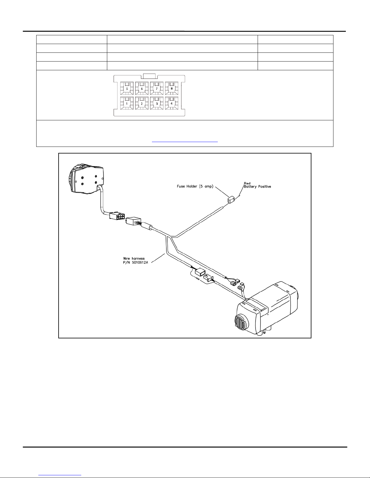
Electrical Connections
This is a plug and play kit for an AT 2000 ST/C, EVO AT
3900/5500, or EVO AT 40/55 Heater. Refer to the compatibility
section for adapter part numbers.
Connector Pin out
2
Page 3
SmarTemp Control Installation - Operating Instructions
5
Analog Output (Temperature Set Point)
Blue
6
Analog Output (Ambient Temperature)
Yellow
7
Vent Input
Purple
8
Diagnostic Input W-Bus
Green
TERMINAL INSERT
SIDE OF CONNECTOR
For terminal removal use: Molex terminal removal tool P/N: 11-03-0044
http://www.molex.com
3
Page 4
SmarTemp Control Installation - Operating Instructions
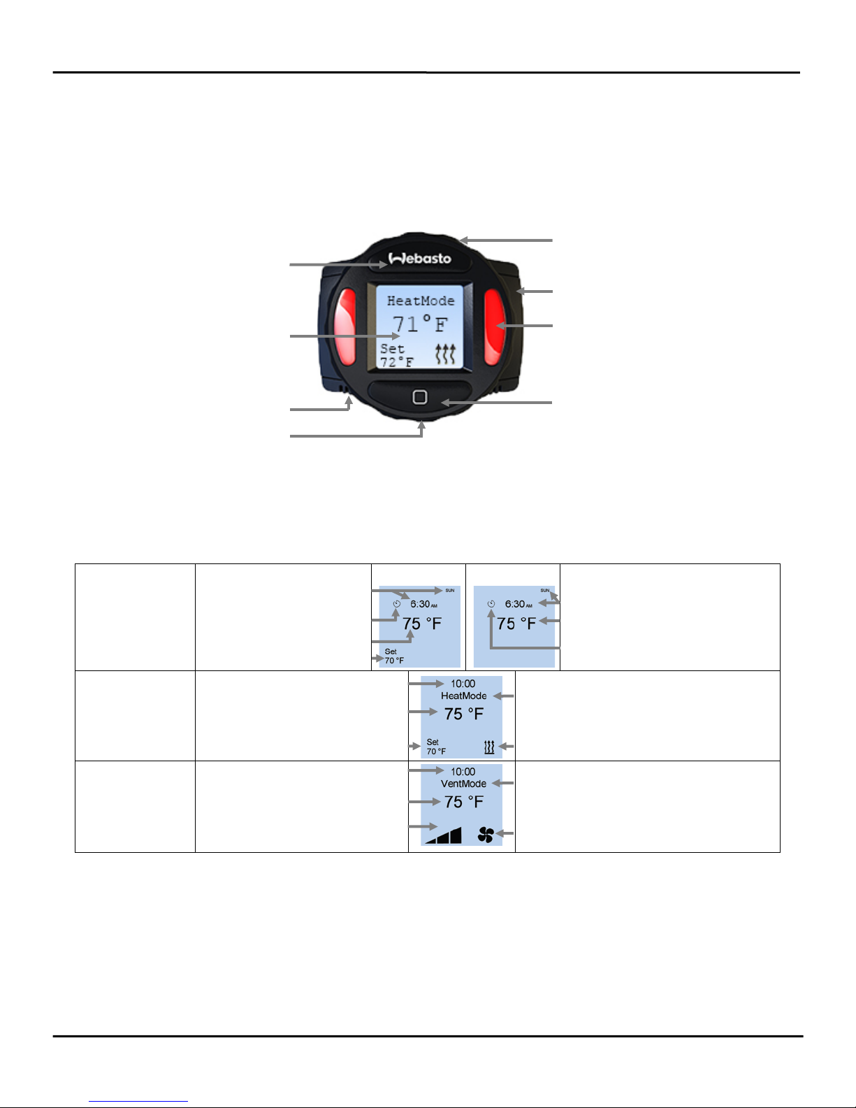
On / Off Button
Screw Cap
Status Indicator Light(s)
Selection Button
Heater Mode
Vent Mode
Timer Start Day / Time
Mode Indicator
Mode Indicator
Temperature Calibration
Based on the installation location of the SmarTemp Control 2.0, multiple factors such as door openings
can affect the SmarTemp Controls ambient temperature reading. If temperature offset adjustment is
needed see “Offset” on page 5Error! Bookmark not defined. for further details.
Component Description
Rotary Knob
LCD Screen
Ambient Temp Sensor
*Micro USB Service Port
* The micro USB Service Port is used for Webasto heater diagnostic purposes only. This port
cannot be used to charge cell phones or other electronic devices.
LCD Screen Symbol Legend
Timer Start Day / Time
Main Screen
Ambient Temperature
Heat Mode
Vent Mode
Timer Active
Set Temperature
Runtime Remaining
Ambient Temperature
User Set Temperature
Runtime Remaining
Ambient Temperature
Fan Speed Indicator (Low –
Medium - High)
Heater ON
Fan ON
Ambient Temperature
Timer Active
Operation Examples
Below are a few operational examples of how easy it is to use the Webasto SmarTemp Control 2.0.
Heater ON Example
Press the Webasto button to turn heater on.
Set Temperature Output & Heater Runtime Example
Using the rotary dial and the selection button, follow these steps to set your cab temperature to 70°F
with a runtime of 4 hours.
4
Page 5

SmarTemp Control Installation - Operating Instructions
1. Press the Selection button. Using the rotary dial, select: Options > Duration > Timed > Adjust
runtime to 4 hours. Confirm the adjustment by pushing the selection button.
2. From the main screen use the rotary dial to adjust the set temperature to 70°F; confirm the
adjustment by pushing the selection button.
NOTE: The set temperature can be adjusted quickly even when the heater is running using the same
method as above.
Set Timer Example
Set timer to turn on Friday at 6:30AM with a runtime of 60 minutes.
1. Press the Selection button. Using the rotary dial, select Timer.
2. Highlight the timer feature, press the Selection button. Select “edit” from the sub-menu.
3. Adjust and select day for Friday.
4. Adjust and select time for 6:30AM.
5. Adjust and select runtime for 60 minutes.
6. Settings are saved each time the selection button is pressed.
Refer to Menu Descriptions Table for a detailed description of each menu item and its default setting.
5
Page 6
SmarTemp Control Installation - Operating Instructions
24 volt - Range between 21v – 25.5v
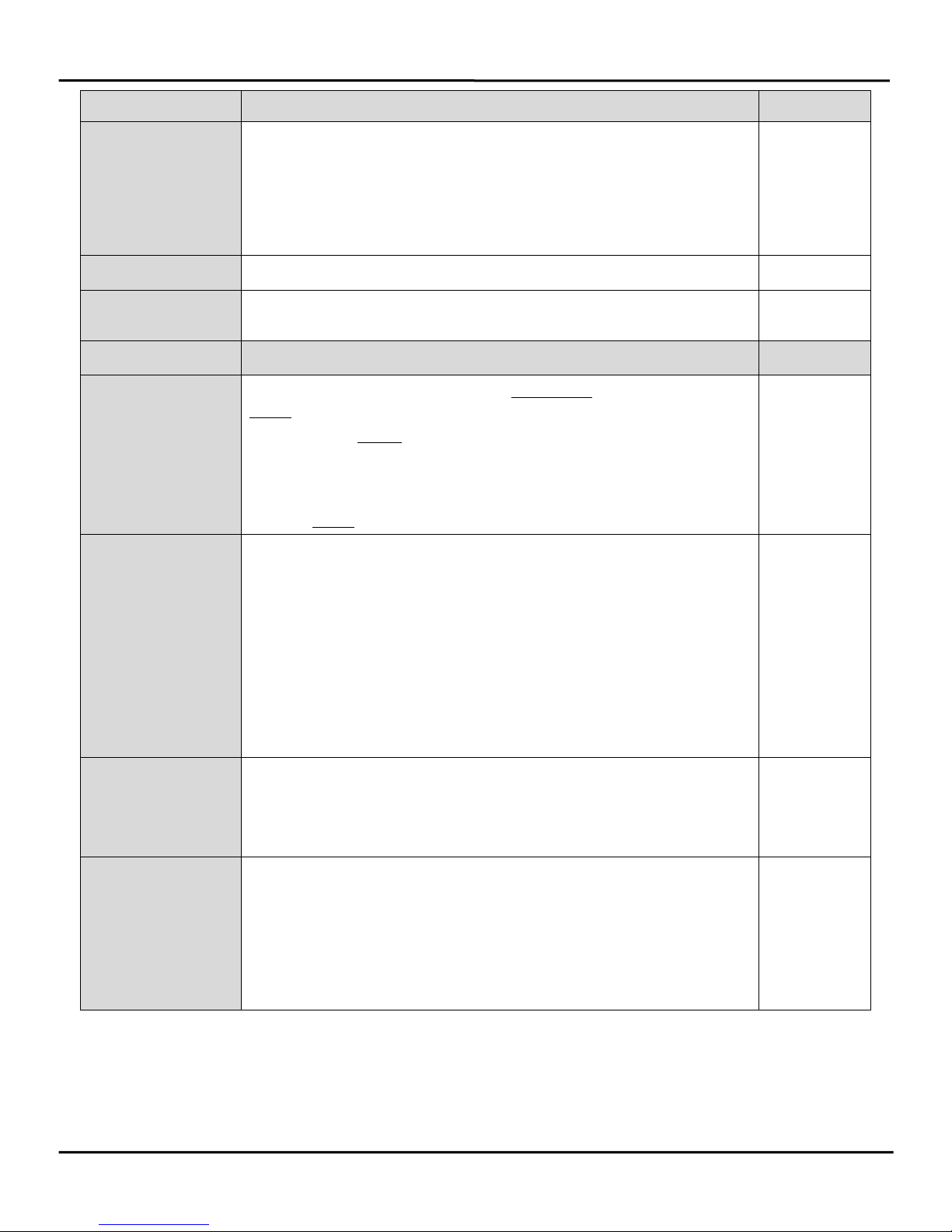
Definitions Default
Mode
Language
Temp Unit
Options
Duration
LVD
Mode changes the operation of the heater between heat mode and
ventilation mode. Status indicator lights will illuminate red for heat
mode and blue for ventilation mode when the selected mode is
active.
Note: Refer to Status Indicator Light description on page 6 for
additional Status Indicator explanation.
Language changes between English, Spanish, and French. English
Temp Unit changes between Fahrenheit and Celsius units of
measure.
Advanced level adjustments; see below.
Duration allows for the selection of continuous heater operation or
timed operation (30 minutes – 14 hours in 30 minute increments).
IMPORTANT: Timed duration is not to be mistaken for Timer
functionality. The duration times above are used when turning the
heater on manually. I.e. set the heater duration for 8 hours before
heading to bed.
Note: If timed operation is selected 10 hours is default.
LVD “Low Voltage Disconnect” allows the user to set the battery
voltage level at which the Webasto SmarTemp Control 2.0 will shut
down the heater. A warning (LED and message) will appear after 8
minutes of low voltage. The warning will remain on for 2 minutes
before the heater is shut off.
If battery voltage is equal to or less than the threshold selected
+0.1v, the heater will not start. I.e. if an 11.5v threshold is selected
the heater cannot be started until B+ has reached 11.7v.
12 volt - Range between 11v – 12.5v
Heat Mode
Fahrenheit
Continuous
11.4v
24.2v
Password
PM Reminder
A password can be set to prevent access to the advanced “Options”
menu. Enter a 4 digit code passcode to begin securing the
“Options” menu.
Note: This is typically used in fleet vehicle applications.
If the heater has not run 30 days, the preventive maintenance (PM)
reminder will alert the operator with a message to run the heater for
20 minutes. The indicator lights will flash red as a visual reminder.
The operator will have the ability to Start the 20 minute
maintenance cycle or delay it via a “Snooze” option. When Snooze
is selected the PM reminder will postpone until 12:00PM the
following day.
OFF
ON
6
Page 7

SmarTemp Control Installation - Operating Instructions
Time & Date
Offset
Default
Timer
Definitions Default
Set time and date using the rotary knob and selection button.
12 hour
12 (AM / PM) or 24 hour available.
The Webasto button can be used to go back to the previous
field if additional changes are needed.
Depending on the installation location, the temperature
0°
reading may vary slightly. The Offset feature allows a
temperature adjustment of +/- 9°F (+/- 5°C). Adjust this as
necessary to obtain the most accurate ambient temperature
reading.
Default allows the user to perform a factory reset of the
N/A
control settings.
NOTE: Heater information will NOT be affected.
User can select a specific day, time and heater runtime up to 7
Off
days in the future. Be aware this is a one occurrence timer
requiring the user to turn the timer “ON” again after each
scheduled timer use.
When selecting timer a sub-menu will appear (Edit, On, and
Off). To modify timer settings, select “edit”. Select the day,
time, and heater runtime using the rotary knob and the
selection button. Settings are saved each time the selection
button is pressed. The heater runtime can be set to 30, 60,
90, or 120 minutes. If the timer function will be used regularly
for next day startups, the “ANY” setting can be used in place
of the day of the week. With this set, the timer will disregard
the day setting and start during the next 24-hour period
based on the time selected. The “ANY” setting is located in
the list of days between Saturday and Sunday.
Error Code
This section will log the last 5 error codes and the date that it
was set. Highlight and select an error code for a full
description. If the heater produces an error code, the status
indicator lights will flash red and the error will display on the
main screen.
NOTE: Heater error codes cannot be reset through the
Webasto SmarTemp Control 2.0; a Webasto PC Diagnostics
tool is required. Refer to the heater service manual for
resetting an error code.
SW Version
This displays the firmware version of the Webasto SmarTemp
Control 2.0.
Back
Select this to return to the previous screen. N/A
No Errors
Installed
Version
7
Page 8

SmarTemp Control Installation - Operating Instructions
Status Indicator Lights - The Red status indicators (heater "ON") and LCD screen backlight turn off
after 30 seconds. A touch of any button or a turn of the rotary knob will re-activate these lights. If the
"Webasto" button is used to re-activate these lights, an additional press of this button is necessary to
turn the heater off. Note that when the heater is "ON" the display is active.
Technical Information:
– Rated Voltage: 12V / 24V
– Operating Voltage Range: 9V - 32V
– Low Voltage Disconnect Range: 12V: 11 – 12.5V | 24V: 21 – 25.5V
– Operating Temperature: - 40° ... +185 °F (- 40° ... +85 °C)
Note: Display visible to -22°F (-30°C)
– Set Temperature Range: 41° - 95° F (5° - 35° C)
– Installation Dimensions: (L x H x D) 2.7” x 2.2” x .60” (69.4mm x 55.5mm x 15.2mm)
Drilling Dimensions
Use the dimensions / template located in the back of this manual as a guide when installing and
mounting the Webasto SmarTemp Control 2.0.
NOTE: The Webasto SmarTemp Control 2.0 has an integrated ambient temperature sensor. To
ensure this sensor properly measures the surrounding air, the unit must only be mounted in the
vertical position.
8
Page 9
Commande SmarTemp 2.0
Interface de commande numérique pour
Chauffages 2000 ST/C –!EVO 3900/5500 –!EVO 40/55
Installation / Mode d'emploi
GENERALITES
Merci d'avoir choisi Webasto pour vos solutions de chauffage. La commande Smar Temp 2.0 de Webasto
vous permet de rapidement et facilement utiliser vos chauffages Webasto mentionnés dans la section
compatibilité.
Fonctionnement
La commande Smar Temp 2.0 de Webasto est la prochaine génération de commandes de la gamme
Smar Temp. Elle fonctionne à l'aide d'un seul cadran rotatif permettant de sélectionner les diverses
options du menu. Veuillez simplement cliquer sur le bouton de sélection ( ) pour faire votre choix.
Compatibilité
AT 2000 ST/C - Faisceau de câbles de l'adaptateur (P/N: 5010612)
AT EVO 3900/5500 & EVO 40/55 - Faisceau de câbles de l'adaptateur (P/N: 5012138)
Procédure de fixation
Plusieurs facteurs, tels que les portes et fenêtres doivent être prises en considération, car elles peuvent
directement affecter la lecture de la température ambiante des commandes SmarTemp. Référez-vous à la
section "Calibration de la température" en page 8 si ces obstacles sont inévitables.
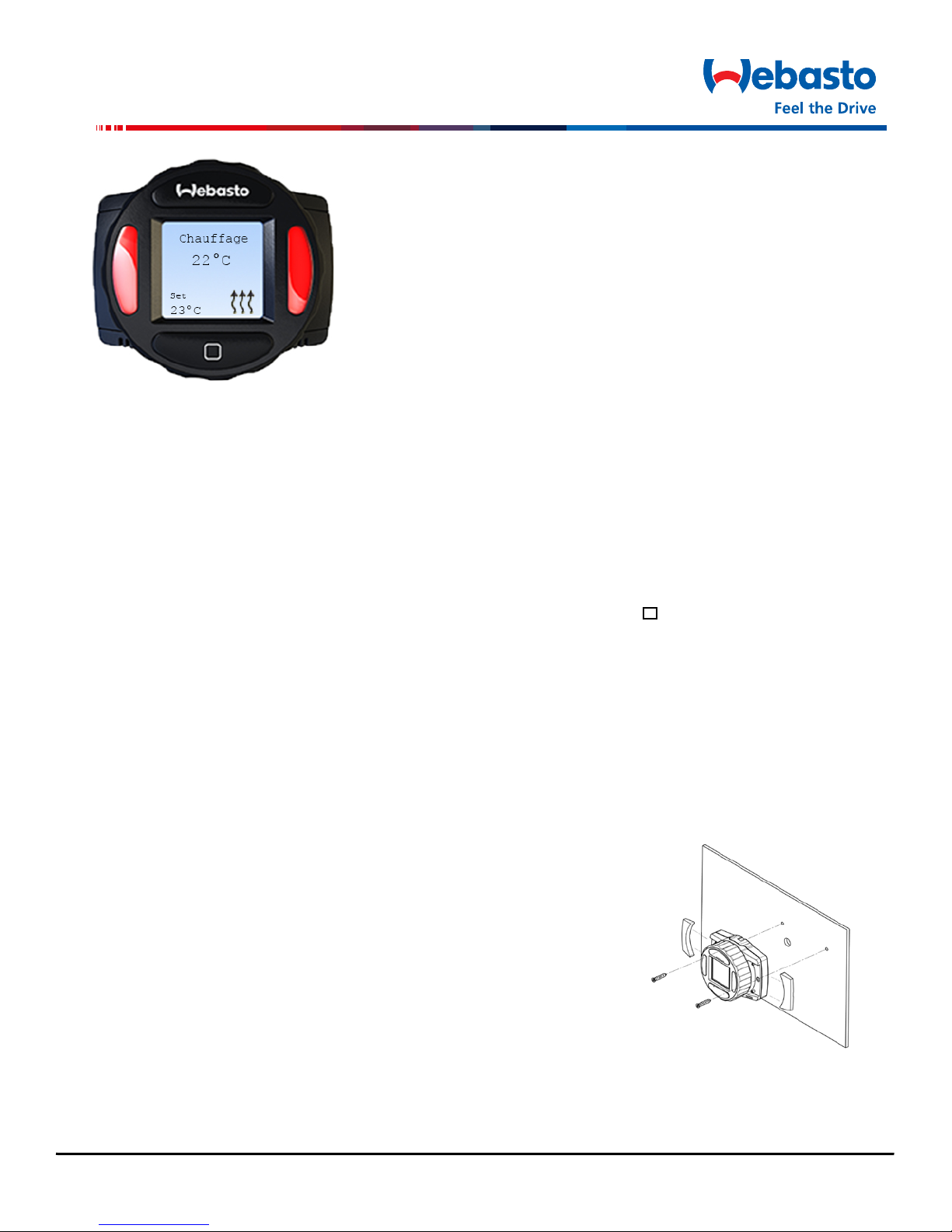
1. Fixez l'unité à un endroit adapté (sur une surface plane si
possible) et dans une zone visible.
ATTENTION : Veillez à toujours installer l'unité dans une zone à
l'abri de l'humidité et de toute poussière pour ne pas que les
fonctionnalités de l'appareil ne soient altérées.
2. Utilisez les dimensions / modèle de perçage stipulés au dos de ce
guide afin de légèrement marquer les deux trous de fixation.
3. (Étape facultative) Afin d'insérer le faisceau de câbles dans la
surface de fixation, percez un trou de 22mm de diamètre, tel
que mentionné sur les dimensions / modèle de perçage.
Remarque : Veillez toujours à ce que la surface de fixation soit libre de tout obstacle avant de
percer.
4. Sécurisez la commande SmartTemp 2.0 de Webasto en utilisant les 4 vis fournies.
9
Page 10

Commande SmarTemp Instruction d’installation – Mode d’emploi
Numéro de broche
Description
Couleur du câble
1
+12 / 24V
Rouge
2
GND
Marron
3
Puissance de chauffage
Noir
4
Code de diagnostic clignotant
Orange
5
Sortie analogique (température de consigne)
Bleu
6
Sortie analogique (température ambiante)
Jaune
7
Entrée d'air
Violet
8
Diagnostic de l'entrée W-Bus
Vert
BORNE D'ALIMENTATION
CÔTÉ DU RACCORD
Branchements électriques
Voici un kit de branchement universel pour un chauffage AT 2000 ST/C, EVO AT 3900/5500, ou EVO AT
40/55. Référez-vous à la section sur la compatibilité pour obtenir les numéros des pièces de l'adaptateur.
Brochage du connecteur
Pour retirer la borne d'alimentation : Outil de retrait de borne d'alimentation Molex P/N : 11-03-0044
http://www.molex.com
10
Page 11

Commande SmarTemp Instruction d’installation – Mode d’emploi
Bouton On / Off
Bouchon à vis
Voyant(s) lumineux de statut
Capteur de température
*Port micro-USB
Bouton de sélection
Mode chauffage
Mode ventilation
Jour / Heure de début du
Minuteur actif
Réglage de la température
Indicateur du mode
Indicateur du mode
Calibration de la température
En fonction du lieu de l'installation de la commande SmarTemp 2.0, plusieurs facteurs, tels que
l'ouverture des portes, peuvent affecter la lecture de température des commandes SmarTemp. Si une
modification de la température de régulation est nécessaire, veuillez consultez la section "Régulation" en
page 12 pour davantage d'informations.
Description de l'élément
Bouton rotatif
Affichage LCD
ambiante
* Le port micro-USB est uniquement utilisé pour les chauffages Webasto. Le port ne peut pas
être utilisé pour charger des téléphones portables ou autres appareils électroniques.
Légende des symboles de l'affichage LCD
minuteur
Écran principal
Température ambiante
Temps d'exécution restant
Mode chauffage
Mode ventilation
Indicateur de vitesse du ventilateur
Température ambiante
Réglage de la température par
l'utilisateur
Temps d'exécution restant
Température ambiante
(faible-moyen-fort)
Chauffage allumé
Ventilateur allumé
Jour / Heure de début du minuteur
Température ambiante
Minuteur actif
11
Page 12

Commande SmarTemp Instruction d’installation – Mode d’emploi
Exemples d'utilisation
Voici quelques exemples démontrant la facilité d'utilisation de la commande Smart Temp 2.0 de
Webasto.
Exemple de chauffage allumé
Appuyez sur le bouton Webasto pour allumer le chauffage.
Exemple de réglage de la température et durée d'exécution du chauffage
A l'aide du cadran rotatif et du bouton de sélection, suivez ces étapes pour réglez votre température sur
21°C avec une durée d'exécution de 4 heures.
1. Appuyez sur le bouton de sélection. A l'aide du cadran rotatif, sélectionnez : Options > Durée >
Minuté > Régler le temps d'exécution sur 4 heures. Confirmez la modification en appuyant sur le
bouton de sélection.
2. A partir du menu principal, utilisez le cadran rotatif pour régler la température définie sur 21°C;
confirmez en appuyant sur le bouton de sélection.
REMARQUE : La température définie peut être rapidement modifiée en utilisant la méthode ci-dessus, et
ce, même lorsque le chauffage est en marche.
Réglage du minuteur
Réglez le minuteur sur Vendredi à 6h30 avec un temps d'exécution de 60 minutes.
7. Appuyez sur le bouton de sélection. A l'aide du cadran rotatif, sélectionnez Minuteur.
8. Sélectionnez la fonctionnalité minuteur, puis appuyez sur le bouton de sélection. Sélectionnez
"modifier" depuis le sous-menu.
9. Ajustez puis sélectionnez la journée de vendredi.
10. Ajustez puis sélectionnez l'heure de 6h30.
11. Ajustez puis sélectionnez le temps d'exécution de 60 minutes.
12. Les réglages sont enregistrés après chaque utilisation du bouton de sélection.
Référez-vous au tableau de description du menu pour obtenir une description détaillée de chaque
fonction, ainsi que ses paramètres par défaut.
12
Page 13

Commande SmarTemp Instruction d’installation – Mode d’emploi
Définitions Par défaut
Mode
Langue
Unité de
température
Options
Le mode sélectionné modifie le fonctionnement du chauffage
entre le mode chauffage et le mode ventilation. Les voyants
Mode
chauffage
lumineux de statut sont de couleur rouge pour le mode
chauffage et de couleur bleue pour le mode ventilation,
lorsque le mode sélectionné est actif.
Remarque : Référez-vous à la description des voyants
lumineux de statut en page 13 pour obtenir davantage
d'informations sur les différents voyants de statut.
Les langues disponibles sont l'anglais, l'espagnol et le français. Anglais
L'unité de température est disponible en unités de mesure
Fahrenheit
Fahrenheit et Celsius.
Modifications du niveau avancées; voir ci-dessous.
13
Page 14

Commande SmarTemp Instruction d’installation – Mode d’emploi
24 volts - Amplitude de 21v à 25.5v
Durée
LVD
Définitions Par défaut
La fonctionnalité durée permet de sélectionner la durée
d'opération continue du chauffage ou la durée d'opération
Continu
minutée (30 minutes à 14 heures par pallier de 30 minutes).
IMPORTANT : L'opération minutée n'est pas la même chose
que la fonctionnalité Minuteur. Les durées ci-dessus sont
utilisées lorsque le chauffage est allumé manuellement. Réglez
la durée d'exécution du chauffage sur 8 heures avant d'aller
vous coucher.
Remarque : Si vous sélectionnez une durée d'exécution
minutée, le temps d'exécution par défaut est de 10 heures.
La "tension de sectionnement basse" (LVD) permet à
l'utilisateur de régler le niveau de tension de la batterie à
laquelle la commande SmarTemp 2.0 de Webasto éteindra le
chauffage. Un avertissement (LED et message) apparaît au
bout de 8 minutes de basse tension. L'avertissement reste
allumé pendant 2 minutes avant de l'appareil de chauffage est
coupé.
Si la tension de la batterie est égale ou inférieure au seuil
sélectionné de +0,1v, le chauffage ne s'allumera pas. Si un
seuil de 11,5v est sélectionné, le chauffage ne peut pas
démarrer avant que B+ ait atteint 11,7v.
11.4v
24.2v
Mot de passe
Rappel de MP
12 volts - Amplitude de 11v à 12.5v
Un mot de passe peut-être configurer pour empêcher l'accès
au menu des "Options" avancées. Entrez un mot de passe à 4
chiffres pour commencer la sécurisation du menu "Options".
Remarque : Ceci est particulièrement utilisé dans les
applications de véhicules de flotte.
Si le chauffage n'a pas fonctionné pendant 30 jours, le rappel
de maintenance préventive (MP) alertera l'utilisateur par un
message de rappel lui indiquant d'allumer d'abord le
chauffage pendant 20 minutes. Les voyants lumineux de
couleur rouge serviront de rappel visuel.
L'utilisateur pourra alors lancer le cycle de maintenance de 20
minutes ou le retarder grâce à l'option "Rappel d'alarme".
Lorsque l'option "Rappel d'alarme" est sélectionnée, le rappel
MP est retardé à midi du jour suivant.
OFF
ON
14
Page 15

Commande SmarTemp Instruction d’installation – Mode d’emploi
Heure & Date
Régulation
Par défaut
Minuteur
Définitions Par défaut
Réglez l'heure et la date à l'aide du cadran rotatif et bouton
12 heures
de sélection. Formats 12 (AM / PM) ou 24 heures disponibles.
Le bouton Webasto peut être utilisé pour revenir au champ
précédent si d'autres changements sont nécessaires.
En fonction du lieu de l'installation, la lecture de la
0°
température peut légèrement varier. La fonctionnalité
Régulation permet une modification de la température de +/5°C (+/- 9°F). Modifiez cette température à votre convenance
pour obtenir la lecture de température ambiante la plus
précise.
Cette fonctionnalité permet à l'utilisateur de réinitialiser les
N/A
paramètres de régalage de l'appareil.
REMARQUE : Les informations relatives au chauffage ne
seront PAS affectées.
L'utilisateur peut sélectionner un jour, une heure spécifique,
Off
ainsi qu'un temps d'exécution pouvant s'élever jusqu'à 7
heures. Ceci est un minuteur à occurrence unique, qui
nécessite d'être rallumé après chaque utilisation programmée.
Lorsque vous sélectionnez le minuteur, un sous-menu
s'affiche (Modifier, On et Off). Pour modifier les réglages du
minuteur, sélectionnez "modifier". A l'aide du cadran rotatif
et bouton de sélection, sélectionnez le jour, heure et durée
d'exécution Les réglages sont enregistrés après chaque
utilisation du bouton de sélection. Le temps d'exécution du
chauffage peut être de 30, 60, 90 ou 120 minutes. Si la
fonction du minuteur est utilisée régulièrement lors des
prochains jours, le réglage "TOUS" peut être utilisé à la place
du jour de la semaine. Grâce à ce réglage, le minuteur
ignorera les paramètres du jour et heure de début pendant les
24 prochaines heures, en fonction de la durée sélectionnée.
La fonctionnalité "TOUS" se situe dans la liste des jours entre
Samedi et Dimanche.
15
Page 16

Commande SmarTemp Instruction d’installation – Mode d’emploi
Code d'erreur
Cette section affiche les 5 derniers codes d'erreur, ainsi que la
date à laquelle il a été réglé. Sélectionnez un code d'erreur
Aucunes
erreurs
pour obtenir sa description complète. Si le chauffage émet un
code d'erreur, les voyants lumineux de couleur rouge
clignoteront et le message d'erreur s'affichera sur l'écran
principal.
REMARQUE : Les codes d'erreur du chauffage ne peuvent pas
être réinitialisés via la commande SmarTemp 2.0 de Webasto;
un outil de diagnostic PC Webasto est requis. Consultez le
guide d'utilisateur du chauffage pour réinitialiser un code
d'erreur.
Version logicielle
(SW)
Retour
Ceci affiche la version de firmware de la commande Smar
Temp 2.0 de Webasto.
Version
installée
Sélectionnez cette option pour revenir au menu précédent. N/A
Voyants lumineux de statut - Les voyants lumineux de couleur rouge (chauffage "ON") et
l'affichage LCD s'éteignent après 30 secondes. Le simple fait de toucher un bouton ou de tourner le
cadran rotatif permet de réactiver ces voyants lumineux. Si le bouton "Webasto" est utilisé pour
réactiver ces voyants lumineux, il vous faudra appuyer de nouveau sur ce bouton pour éteindre le
chauffage. N'oubliez pas que lorsque le chauffage est allumé, l'affichage est actif.
Caractéristiques techniques :
– Tension nominale : 12V / 24V
– Étendue de la tension d'alimentation : 9V - 32V
– Tension de sectionnement basse : 12V: 11 –!12.5V | 24V: 21 –!25.5V
– Température de fonctionnement : - 40° ... +185 °F (- 40° ... +85 °C)
Remarque : Affichage visible jusqu'à -30°C (-22°F)
– Réglage de la plage de température : 41° - 95° F (5° - 35° C)
– Dimensions de l'installation : (L x H x D) 2.7� x 2.2� x .60� (69.4mm x 55.5mm x 15.2mm)
Dimensions de perçage
Utilisez les dimensions / modèle de perçage stipulés au dos de ce guide lors de l'installation et
fixation de la commande Smar Temp 2.0 de Webasto.
REMARQUE : La commande Smar Temp 2.0 de Webasto est équipée d'un capteur de température
ambiante intégré. Afin que le capteur mesure correctement la température environnante, l'unité doit
uniquement être installée de manière verticale.
16
Page 17

Controlador SmarTemp 2.0
Interface de control digital para Calefactores
Air Top 2000 ST/C – EVO 3900/5500 – EVO 40/55
Instalación / Instrucciones de operación
General
Gracias por elegir Webasto para satisfacer sus necesidades de calefacción. El Webasto SmarTemp Control
2.0 le permite operar rápidamente y sin esfuerzo los calefactores de aire Webasto especificados en la
sección de compatibilidad.
Operación
El Webasto SmarTemp Control 2.0 es la próxima generación de la serie de controladores de SmarTemp.
Se opera usando un comando giratorio único en el borde de la unidad que le permitirá desplazarse por
las opciones del menú. Simplemente haga clic en el botón para seleccionar ( ) para hacer su elección.
Compatibilidad
AT 2000 ST/C - Arnés adaptador (P/N: 5010612)
AT EVO 3900/5500 & EVO 40/55 - Arnés adaptador (P/N: 5012138)
Procedimiento de montaje
Se deben considerar múltiples factores, como puertas y ventanillas, ya que pueden afectar directamente
las lecturas de la temperatura ambiental del SmarTemp Control. Consulte la sección de «Calibración de
temperatura» en la página 15 si estos obstáculos son inevitables.
1. Elija una ubicación adecuada para el montaje (en una superficie plana, si es posible) en un área
visible.
PRECAUCIÓN: Siempre instale la unidad en un área protegida de
los efectos del clima y la contaminación de polvo o la unidad no
funcionará de la manera prevista.
2. Utilice la plantilla de dimensiones para las perforaciones al dorso
de este manual para marcar suavemente los dos agujeros
necesarios para el montaje.
3. (Paso opcional) Para ubicar el arnés de alambre en la superficie
de montaje, realice un agujero de 22 mm como se indica en la
plantilla de dimensiones para las perforaciones.
Importante: Asegúrese siempre de que no haya obstáculos detrás
de la ubicación del montaje antes de realizar la perforación.
4. Asegure el Webasto SmarTemp Control 2.0 usando los dos tornillos #4 provistos.
17
Page 18

Instalación de SmarTemp Control Instrucciones de operación
Número de Pin
Descripción
Color del cable
1
+12 / 24V
Rojo
2
Tierra
Marrón
3
Salida del calefactor
Negro
4
Código de parpadeo de diagnóstico
Naranja
5
Salida analógica (Punto de configuración de la
temperatura)
Azul
6
Salida analógica (Temperatura ambiente)
Amarillo
7
Entrada de ventilación
Violeta
8
W-Bus de entrada de diagnóstico
Verde
LADO DE LA
ENTRADA DE LA
Conexiones eléctricas
Los calefactores AT 2000 ST/C, EVO AT 3900/5500, o EVO AT 40/55 cuentan con un kit Plug & Play.
Consulte la sección de compatibilidad sobre los números de partes del adaptador.
Salida del pin conector
Para retirar la terminal utilice: Herramienta para retirar la terminal Molex P/N: 11-03-0044
http://www.molex.com
18
Page 19

Instalación de SmarTemp Control Instrucciones de operación
Botón On/Off
Tapa del tornillo
Luz indicadora de estado
Sensor de temperatura
USB
Botón de selección
Modo calefacción
Modo ventilación
Temporizador Día / Hora
Temporizador activo
Indicador de modo
Indicador de modo
Calibración de temperatura
Basado en la ubicación de la instalación del SmarTemp Control 2.0, múltiples factores, como aperturas
de puertas, pueden afectar las lecturas de la temperatura ambiente del SmarTemp Control. Si se necesita
hacer un ajuste en la calibración de la temperatura, consulte «Calibración» en la página 19 para obtener
más detalles.
Descripción de los componentes
Comando giratorio
Pantalla LCD
ambiente
* Puerto de servicio micro
* El puerto de servicio micro USB se utiliza para diagnosticar el calefactor Webasto solamente.
Este puerto no puede usarse para cargar teléfonos celulares u otros dispositivos electrónicos.
Leyendas de los símbolos de la pantalla LCD
Temporizador Día / Hora
Pantalla principal
Temperatura ambiente
Temperatura configurada
Tiempo restante
Modo calefacción
Temperatura configurada por el
Modo ventilación
ventilador (Bajo - Medio - Fuerte)
Temperatura ambiente
usuario
Tiempo restante
Temperatura ambiente
Indicador de velocidad del
Calefacción ON
Ventilador ON
Temperatura ambiente
Temporizador activo
19
Page 20

Instalación de SmarTemp Control Instrucciones de operación
Ejemplos de operación
A continuación encontrará algunos ejemplos de operación y verá cuan fácil es usar el Webasto
SmarTemp Control 2.0.
Ejemplo para encender la calefacción
Presione el botón Webasto para encender la calefacción.
Ejemplo para indicar la temperatura de salida y el temporizador del calefactor
Usando el comando giratorio y el botón de selección, siga los siguientes pasos para configurar la
temperatura de la cabina a 70°F con un tiempo de operación de 4 horas.
1. Presione el botón de Selección. Usando el comando giratorio, seleccione: Opciones > Duración >
Temporizado > Ajustar tiempo de operación a 4 horas. Confirme el ajuste presionando el botón
de selección.
2. Desde la página principal, use el comando giratorio para ajustar la temperatura a 70°F; confirme
el ajuste presionando el botón de selección.
IMPORTANTE: La temperatura configurada puede ajustarse rápidamente cuando el calefactor está
funcionando usando el mismo método descripto anteriormente.
Ejemplo de configuración del temporizador
Configure el temporizador para encenderse el viernes a las 6:30 am con un tiempo de operación de 60
minutos.
13. Presione el botón de Selección. Usando el comando giratorio, seleccione Temporizador.
14. Resalte la selección del temporizador, presione el botón de Selección. Seleccione «editar» del
submenú.
15. Ajuste y seleccione el día en viernes.
16. Ajuste y seleccione la hora en 6:30 am.
17. Ajuste y seleccione el tiempo de operación en 60 minutos.
18. La configuración se graba cada vez que presiona el botón de selección.
Consulte la Tabla de descripción del menú para obtener una explicación más detallada de cada elemento
del menú y su configuración por defecto.
20
Page 21

Instalación de SmarTemp Control Instrucciones de operación
Modo
Idioma
Unidad de
temperatur
a
Opciones
Definiciones Por defecto
El modo cambia la operación del calefactor entre modo
Modo calefacción
calefacción y modo ventilación. Las luces indicadoras de
estado se iluminarán en rojo para el modo calefacción y en
azul para el modo ventilación cuando el modo
seleccionado esté activo.
Importante: Consulte las descripción de la Luz indicadora
de estado en la página 20 para obtener más información
sobre el Indicador de estado.
Los idiomas disponibles son inglés, español, y francés. Inglés
La unidad de temperatura cambia entre las unidades de
Fahrenheit
medidas de Fahrenheit y Celsius.
Ajustes de nivel avanzado; consulte a continuación.
21
Page 22

Instalación de SmarTemp Control Instrucciones de operación
24 volt - Rango entre 21v – 25.5v
Duración
DBV
Definiciones Por defecto
La duración permite seleccionar entre operación de
calefacción continua u operación temporizada (30
Continuo
minutos - 14 horas en incrementos cada 30 minutos)
IMPORTANTE: La duración de temporizado no debe
confundirse con la función de temporización. Los tiempos
de duración descriptos anteriormente se usan cuando el
calefactor se enciende manualmente. Por ejemplo, cuando
se configura la duración de la calefacción a 8 horas antes
de ir a la cama.
Importante: Si se selecciona la operación temporizada
serán 10 horas por defecto.
DBV «Desconexión a bajo voltaje» le permite al usuario
configurar el nivel de voltaje de la batería en el cual el
Webasto SmarTemp Control 2.0 apagará la calefacción.
Una advertencia (LED y el mensaje ) aparecerá después de
8 minutos de baja tensión. La advertencia permanecerá
encendida durante 2 minutos hasta que la estufa se
apaga.
Si el voltaje de la batería es igual o menor al límite
seleccionado de +0.1v, la calefacción no se encenderá. Es
decir, si se selecciona un umbral de 11.5v, la calefacción
no podrá comenzar hasta que la batería haya alcanzado
11.4v
24.2v
11.7v.
Contrase
Recordat
ña
orio de
MP:
12 volt - Rango entre 11v – 12.5v
Se puede configurar una contraseña para evitar el acceso
al menú de Opciones avanzadas. Ingrese una contraseña
de 4 dígitos para comenzar a asegurar el menú Opciones.
Importante: Esto se utiliza típicamente en aplicaciones en
vehículos de flota.
Si la calefacción no se ha usado en 30 días, el recordatorio
de mantenimiento de prevención (MP) alertará al operador
con un mensaje para encender la calefacción durante 20
minutos. Las luces indicadoras se encenderán en rojo
como un recordatorio visual.
El operador tendrá la posibilidad de comenzar el ciclo de
mantenimiento de 20 minutos o retrasarlo con un botón
de «Snooze». Cuando se selecciona el Snooze, el
recordatorio de MP se pospondrá hasta las 12:00 pm del
día siguiente.
OFF
ON
22
Page 23

Instalación de SmarTemp Control Instrucciones de operación
Definiciones
Por defecto
Día & Hora
Calibración
Por defecto
Temporizador
Seleccione el día y la hora con el comando giratorio y el botón
de selección. Están disponibles los formatos 12 (am / pm) o 24
horas.
El botón Webasto puede usarse para regresar al campo
anterior en caso de necesitar hacerse cambios adicionales.
Según la ubicación de la instalación, la lectura de temperatura
puede variar levemente. La característica de calibración
permite un ajuste de temperatura de +/- 9°F (+/- 5°C).
Ajústelo como sea necesario para obtener la lectura de
temperatura ambiente más precisa.
Por defecto le permite al usuario realizar un reseteo a fábrica
de la configuración del control.
IMPORTANTE: La información del calefactor NO se verá
afectada.
El usuario puede seleccionar un día, una hora y un tiempo de
operación específico hasta 7 días en el futuro. Tenga en
cuenta que esta es una temporización de una vez y requiere
que el usuario coloque el temporizador en ON otra vez luego
de cada uso del temporizador seleccionado.
Cuando seleccione el temporizador, aparecerá un submenú
(Editar, On, y Off). Para modificar las características del
temporizador, seleccione «Editar». Seleccione el día, la hora y
el tiempo de operación del calefactor usando el comando
giratorio y el botón de selección. La configuración se graba
cada vez que presiona el botón de selección. El tiempo de
operación del calefactor puede configurarse en 30, 60, 90 o
120 minutos. Si la función de temporizador se usará
regularmente para el encendido al día siguiente, la selección
«ANY» puede usarse en lugar de ingresar el día de la semana.
Con esta configuración, el temporizador ignorará la
configuración de día y comenzará en el siguiente período de
24 horas en base a la hora seleccionada. La configuración
«ANY» está ubicada en la lista de días entre sábado y
domingo.
12 horas
0°
N/A
Off
23
Page 24

Instalación de SmarTemp Control Instrucciones de operación
Definiciones
Por defecto
Código de
error
Versión del
software
Atrás
Luces indicadoras de estado - Los indicadores de estado rojos (calefactor ON) y la luz de la pantalla
LCD se apagan luego de pasados 30 segundos. Al presionar cualquier botón o al rotar el comando
giratorio se reactivarán las luces. Si se usa el botón Webasto para reactivar estas luces, se necesitará
presionar este botón nuevamente para apagar el calefactor. Note que cuando el calefactor está en
«ON», la pantalla está activa.
Esta sección registrará los últimos 5 códigos de error y la fecha
en la que fue configurado. Resalte y seleccione un código de
error para obtener una descripción completa. Si el calefactor
produce un código de error, las luces indicadoras de estado se
encenderán en rojo y se mostrará el error en la pantalla
principal.
IMPORTANTE: Los códigos de error del calefactor no pueden
resetearse con el Webasto SmarTemp Control 2.0; se requiere
una herramienta de diagnóstico Webasto para PC. Consulte el
manual de reparación del calefactor para saber cómo resetear
un código de error.
Se indica la versión de firmware del Webasto SmarTemp
Control 2.0.
Seleccione para regresar a la pantalla anterior. N/A
Sin errores
Versión
instalada
Información técnica:
– Voltaje nominal: 12V / 24V
– Rango de voltaje de operación: 9V - 32V
– Rango de desconexión de bajo voltaje: 12V: 11 – 12.5V | 24V: 21 – 25.5V
– Temperatura de operación: - 40° ... +185 °F (- 40° ... +85 °C)
Importante: Pantalla visible a -22°F (-30°C)
– Rango de temperatura configurada: 41° - 95° F (5° - 35° C)
– Dimensiones de instalación: (L x H x D) 2.7” x 2.2” x .60” (69.4mm x 55.5mm x 15.2mm)
Dimensiones de perforación:
Utilice la plantilla de dimensiones ubicada en el dorso de este manual como guía cuando instale y
monte el Webasto SmarTemp Control 2.0.
IMPORTANTE: El Webasto SmarTemp Control 2.0 tiene un sensor de temperatura ambiente
integrado. Para asegurarse de que el sensor mida el aire de alrededor con precisión, la unidad debe
ser montada solamente en posición vertical.
24
Page 25

Use 5/64 Drill Bit Utilisez une meche de 5/64 Usar 5/64 boquilla
TOP
HAUT
SUPERIOR
Page 26

Page 27

Page 28

Webasto Thermo & Comfort N.A., Inc.
Fenton, MI 48430 USA
Phone:
810-593-6000
http://www.techwebasto.com
Org. 3/2015 Rev. 2/2019 Ver. 1.2 P/N: 5011381B
15083 North Road
Fax:
Email:
Internet:
810-593-6001
info-us@webasto.com
http://www.webasto.us
 Loading...