

Page 1

Air heaters
Integrated heater
10/2009
9019782B
03/2003
Workshop Manual
Dual Top RHA-100
Dual Top RHA-101/102
Page 2
Improper installation or repair of Webasto heating and cooling systems can cause fire or the
leakage of deadly carbon monoxide leading to serious injury or death.
To install and repair Webasto heating and cooling systems you need to have completed a
Webasto training course and have the appropriate technical documentation, special tools and
special equipment.
NEVER try to install or repair Webasto heating or cooling systems if you have not completed a
Webasto training course, you do not have the necessary technical skills and you do not have
the technical documentation, tools and equipment available to ensure that you can complete
the installation and repair work properly.
ALWAYS carefully follow Webasto installation and repair instructions and heed all WARNINGS.
Webasto rejects any liability for problems and damage caused by the system being installed by
untrained personnel.
Page 3

Dual Top Table of Contents
I
Table of Contents
1 Introduction .......................................................................................................................101
1.1 Contents and purpose .............................................................................................................................101
1.1.1 Use of the integrated heaters ........................................................................................................101
1.2 Meaning of signal words .........................................................................................................................101
1.3 Additional documentation to be used .....................................................................................................101
1.4 Statutory regulations and safety instructions ...........................................................................................101
1.4.1 Statutory regulations governing installation ...................................................................................101
1.4.2 General safety information ............................................................................................................101
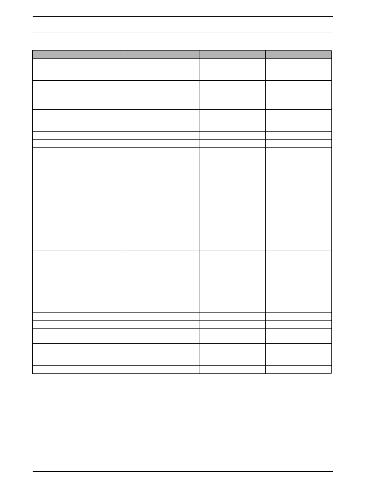
2 Technical data ...................................................................................................................201
3 Fault code output ..............................................................................................................301
3.1 Manual Control Panel .............................................................................................................................301
3.2 Programmable Control Panel ...................................................................................................................304
4 Function tests ....................................................................................................................401
4.1 General ...................................................................................................................................................401
4.2 Repair Shop Level Testing ........................................................................................................................401
4.2.1 Testing individual components ......................................................................................................401
4.2.1.1 Glowplug resistance test ...................................................................................................401
4.2.1.2 Air temperature sensor resistance test ...............................................................................401
4.2.1.3 Water temperature sensor resistance test ..........................................................................401
4.2.1.4 Air temperature switch .....................................................................................................402
4.2.1.5 Water temperature switch ................................................................................................402
4.2.1.6 Overheating protector .......................................................................................................402
5 Circuit diagrams ................................................................................................................501
5.1 General ...................................................................................................................................................501
5.2 Legend for circuit diagram ......................................................................................................................508
6 Servicing work ..................................................................................................................601
6.1 General ...................................................................................................................................................601
6.2 Work on the heater .................................................................................................................................601
6.3 Work on the vehicle ................................................................................................................................601
6.4 Heater test run ........................................................................................................................................601
6.5 Servicing work ........................................................................................................................................601
6.6 Visual inspections and installation instructions .........................................................................................601
6.7 Removal and installation .........................................................................................................................601
6.7.1 Heater, removal and installation ....................................................................................................601
6.7.1.1 Removal ............................................................................................................................601
6.7.1.2 Installation ........................................................................................................................602
6.7.2 Control Panel, removal and installation .........................................................................................602
6.7.2.1 Manual version (for RHA 100) ...........................................................................................602
6.7.2.2 Programmable version (for RHA 100/101/102) ..................................................................602
6.7.2.3 Installation ........................................................................................................................602
6.8 Start-up ..................................................................................................................................................602
Page 4

Table of Contents Dual Top
II
7 Repair .................................................................................................................................701
7.1 General .................................................................................................................................................. 701
7.1.1 Work on stripped-down components ........................................................................................... 701
7.1.1.1 Cleaning .......................................................................................................................... 701
7.1.1.2 Visual inspection .............................................................................................................. 701
7.2 Dismantling ............................................................................................................................................ 701
7.3 Assembling ............................................................................................................................................ 708
7.4 Replacement of older to newer type Dual Top RHA 100 ......................................................................... 715
8 Packaging, storage and shipping .....................................................................................801
8.1 General .................................................................................................................................................. 801
Page 5
Dual Top 1 Introduction
101
1 Introduction
1.1 Contents and purpose
This workshop manual is designed to assist trained personnel with repairing the Dual Top integrated heaters.
1.1.1 Use of the integrated heaters
The Webasto Dual Top integrated air / water heaters are designed to heat and to provide hot water in motor homes
and similar vehicles.
The heaters operate independently of the engine and are
connected to the fuel tanks and the service battery of the
vehicle.
The heaters are not designed for heating vehicles transporting hazardous substances.
1.2 Meaning of signal words
Throughout this manual, the signal words WARNING, IMPORTANT and NOTE have the following meanings:
WARNING
This heading is used to highlight operating instructions or
procedures which, if not or not correctly followed, may result in personal injury or fatal accidents.
IMPORTANT
This heading is used to highlight operating instructions or
procedures which, if not or not correctly followed, may result in damage to the equipment or its components.
NOTE
This heading is used to direct your attention to a special feature deemed essential to highlight.
1.3 Additional documentation to be used
This workshop manual contains most of the information
and instructions required for repairing the Dual Top integrated heaters.
However, it is necessary to read additional documentation.
The operating / installation instructions and the installation
suggestion for the specific vehicle (if available) shall also be
used.
1.4 Statutory regulations and safety
instructions
In principle, the general accident prevention regulations and
current works safety instructions are applicable. The "General safety regulations" that go beyond the scope of the
above regulations are stated below.
Any special safety regulations relevant to this instruction
manual will be highlighted in the relevant sections or text
passages of the procedures.
1.4.1 Statutory regulations governing installation
The Dual Top heaters have been type-tested and approved
in accordance with EC Directives 72/245/EEC (EMC) and
2001/56/EC (heater) with the following EC permit numbers:
e1 03 5000
e1 00 0195.
Installation is governed above all by the provisions in Annex
VII of Directive 2001/56/EC and the regulations in the installation instructions.
NOTE
The provisions of these Directives are binding within
the territory governed by EU Directive 70/156/EEC and/
or 2007/46/EC should similarly be observed in countries without specific regulations!
Installation of the Dual Top RHA 101/102 heater and related
components must be in accordance with IEC 60364 (“Electrical installations in caravan parks and caravans”).
IMPORTANT
Dual Top RHA 101/102: you have to be certified to work on
230 V electric systems. Installation and all other jobs carried
out by none certified persons can cause personal injury to
you, the Dual Top and the vehicle. In that case, Webasto will
refuse all liability.
IMPORTANT
Failure to follow the installation instructions and the notes
contained therein will lead to all liability being refused by Webasto. The same applies if repairs are carried out incorrectly or
with the use of parts other than genuine spare parts. This will
result in the invalidation of the type approval for the heater
and therefore of its
homologation / EC type licence
.
NOTE
For vehicles with an EU permit, no entry in accordance with
§ 19 Sub-Section 4 of Annex VIII b to the Road Traffic Act is
required.
1.4.2 General safety information
Follow all the safety information described in the additional
documentation thoroughly.
Page 6
1 Introduction Dual Top
102
Page 7
Dual Top 2 Technical data
201
2Technical data
Except where limit values are specified, the technical data
refer to the usual heater tolerances of ± 10 % at an ambient
temperature of + 20 °C and at the rated voltage and in rated
conditions.
Fuel for Dual Top
The diesel fuel specified by the manufacturer must be used.
Class EL heating oil, L heating oil or PME (bio-diesel) must
not be used.
Fuel additives have no negative influences on the heater. If
fuel is extracted from the vehicle‘s tank, follow the additive
instructions issued by the vehicle manufacturer.
After changing to low-temperature fuel, the heater must be
operated for approx. 15 minutes so that the fuel system is
filled with the new fuel.
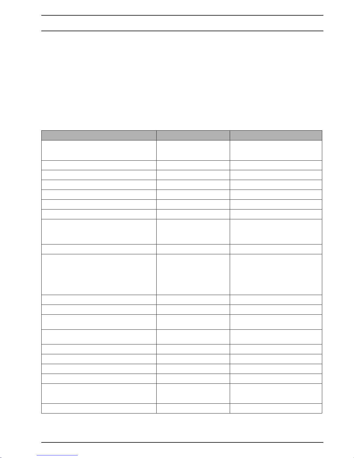
Table 201: Technical data RHA 100
Heater Operation Dual Top RHA 100
Type approval
heater:
EMC:
e1 00 0195
e1 03 5000
Model Air heater with evaporator burner
Heat output Control range 1.5 - 6.0 kW
Fuel Diesel, DIN/EN 590
Fuel consumption Control range 0.17 - 0.65 l/h
Rated voltage 12 V
Operating voltage range 10.5 - 15 V
Current input at 12V Summer mode
Winter mode, heat and hot
water
Stand-by
< 1 A
0.5 ~ 7 A
0.001 A
Rated power consumption Control range 15 - 65 W (EN 1646)
Max. ambient temperature:
Heater:
- Operation
- Storage
Control Panel:
- Operation
- Storage
-30 ~ +50 °C
-40 ~ +85 °C
-30 ~ +75 °C
-40 ~ +85 °C
Max. altitude (guaranteed function) 2,200 m
Adjustment range for interior temperature Control range +5 ~ +35 °C
Delivery rate for hot air (free blowing without
warm-air duct)
Maximum 200 m
3
/h
CO
2
in exhaust gas (permitted function range) 2 kW
6 kW
5.0 ~ 8.0
9.0 ~ 13
Water capacity 11 l
Water system pressure max. 3,5 bar
Overpressure valve 4.0 bar
Pressure water pump, central water supply Maximum 2.5 bar
Heater dimensions Length: 530 ± 2 mm
Width: 352 ± 1 mm
Height: 256 ± 1 mm
Weight (w/o water contents) 20 kg
Page 8
2 Technical data Dual Top
202
Table 202: Technical data RHA 101/102
Heater Operation Dual Top RHA 101 Dual Top RHA 102
Type approval
heater:
EMC:
e1 00 0195
e1 03 5000
e1 00 0195
e1 03 5000
Model Air heater with
evaporator burner
and electric heating
device
Air heater with
evaporator burner
and electric heating
device
Heat output
diesel
electric
Control range 1.5 - 6.0 kW
0.6 - 1.2 kW
1.5 - 6.0 kW
1.0 - 2.0 kW
Fuel Diesel, DIN/EN 590 Diesel, DIN/EN 590
Fuel consumption Control range 0.17 - 0.65 l/h 0.17 - 0.65 l/h
Rated voltage 12 V 12 V
Operating voltage range 10.5 - 15 V 10.5 - 15 V
Current input at 12V Summer mode
Winter mode, heat and hot
water
Stand-by
< 1 A
0.5 ~ 7 A
0.001 A
< 1 A
0.5 ~ 7 A
0.001 A
Rated power consumption Control range 15 - 65 W (EN 1646) 15 - 65 W (EN 1646)
Max. ambient temperature:
Heater:
- Operation
- Storage
Control Panel:
- Operation
- Storage
-30 ~ +50 °C
-40 ~ +85 °C
-25 ~ +50 °C
-40 ~ +85 °C
-30 ~ +50 °C
-40 ~ +85 °C
-25 ~ +50 °C
-40 ~ +85 °C
Max. altitude (guaranteed function) 2,200 m 2,200 m
Adjustment range for interior
temperature
Control range +5 ~ +35 °C +5 ~ +35 °C
Delivery rate for hot air (free blowing
without warm-air duct)
Maximum > 200 m
3
/h > 200 m3/h
CO
2
in exhaust gas (permitted
function range)
2 kW
6 kW
5.0 ~ 8.0
9.0 ~ 13
5.0 ~ 8.0
9.0 ~ 13
Water capacity 11 l 11 l
Water system pressure max. 3,5 bar max. 3,5 bar
Overpressure valve 4.0 bar 4.0 bar
Pressure water pump, central water
supply
Maximum 2.5 bar 2.5 bar
Heater dimensions Length: 530 ± 2 mm
Width: 352 ± 1 mm
Height: 256 ± 1 mm
Length: 530 ± 2 mm
Width: 352 ± 1 mm
Height: 256 ± 1 mm
Weight (w/o water contents) 21 kg 21 kg
Page 9
Dual Top 3 Fault code output
301
3 Fault code output
NOTE
This chapter describes the fault codes given out by the manual and programmable Control Panels.
Replacement of parts, dismantling and assembly (e.g. for inspection and cleaning) is described in chapter 7: "Repair".
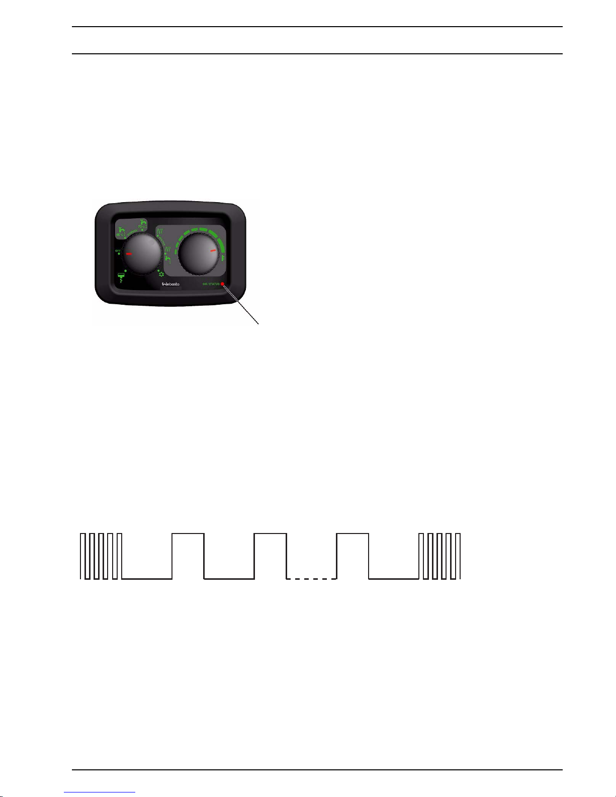
3.1 Manual Control Panel
Abb. 301 Manual Control Panel
The manual Control Panel is used for RHA 100 heaters only.
The heater is able to identify faults on individual
components and during the operation.
The Control Panel gives out the fault code in a flashing
mode.
After a series of 5 fast GREEN flashes, the fault code output
will be a repeated sequence of long RED flashes. After that,
again there will be 5 fast GREEN flashes. This process is
repeated until the heater is switched off. The meaning of
the number of red flashes is shown in: Table 301: "Fault
messages manual Control Panel".
Rectify the cause of the fault.
To reset the fault, switch the heater off (at least 5 seconds)
and then turn back on.
If serious malfunctions such as overheating or failure to start
reoccur, the heater is locked and can be put back into service by deleting the failures.
Do this by disconnecting the power supply (e.g. by removing
all 3 fuses in this sequence: 5A, 10A, 15A; inserting the fuses in reversed order), while the appliance is switched on (see
Operating Instructions, mode selector knob in position 1, 2,
3, 4 or 5), but the heater is not running (to be judged by the
sound of the heater).
Deleting failures can also be done with the Webasto Thermo
Test PC-Diagnosis.
If a fault occurs, the heater stops. In case of electrical safety/
drain valve fault (17 red flashes), heating of the interior is
still possible.
Fig. 302 Example of fault code
LED
“n” x red 5 x green5 x green
1“n”2
Page 10
3 Fault code output Dual Top
302
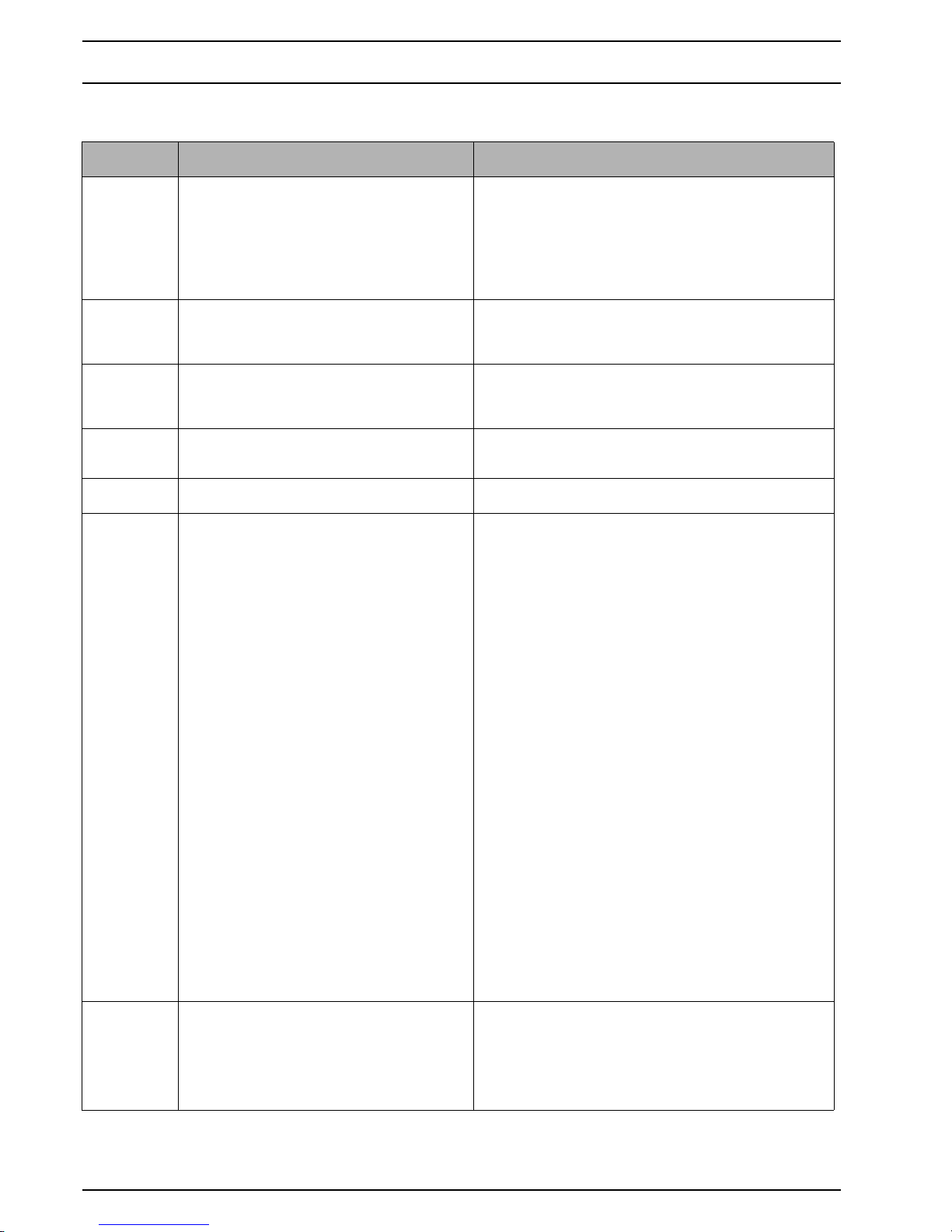
Table 301: Fault messages manual Control Panel
Number of
RED flashes
Meaning Remedy
00 No communication between Control Panel and
heater, or error Control Panel
1 First, remove fuses 15A and 5A. Then put in fuse 15A,
followed by fuse 5A.
2 Check connections of Control Panel.
3 Check fuse 15A.
4 Check wiring harness.
5 Replace Control Panel (see chapter 6: "Servicing
work").
6 Replace control unit.
01 No start (after 2 attempts to start) 1 Check fuel supply (enough fuel, at least 8 ltr.; check
fuel connection and tubes), reset heater (by switching
off for at least 30 sec.).
2 Clean burner insert.
02 Flame failure (at least > 3) 1 Check fuel supply (enough fuel, at least 8 ltr.; check
fuel connection and tubes), reset heater (by switching
off for at least 30 sec.).
2 Clean burner insert.
03 Under voltage or over voltage Charge battery or connect to another power source (DC,
12V or charger 230V),
reset heater (by switching off for at least 5 sec.)
04 Fuel pump disconnection / short circuit /
overheating
1 Check fuel pump cable and connectors.
2 Check internal wiring harness connections Y9, Y10.
05 Hot air motor fault: disconnection / short circuit
/ fan speed out of range / fan blocked
1 Let heater cool down.
Check power supply:
Fuse correct (fuse not damaged, 10A fuse used for
PWM module) and functioning.
All contacts are correct (no corrosion).
Voltage correct (>12V).
Restart heater.
2 Start blower: component test in diagnostic mode.
Run blower 5 minutes at 80%.
Listen if there is any unusual noise (grinding, etc.).
Restart heater.
3 Dismount application parts until the fan is visible.
Check if dirt, screws, objects or deformations block
the fan.
Check fan clearance with your finger (no high force!).
Remove all matters that block the fan.
Restart heater.
4 Remove service cap.
Check all electrical connectors.
Moisture in connectors (2-pin connector and 4-pin
connector)?
Moisture in connectors or on PWM module?
PWM module dark or burned?
12V power supply permanently available at PWM
module? (measure voltage between brown and red/
blue cable contacts of 4-pin connector) If not, check
external wiring harness: routing wiring harness and
pins of 12 pin connector.
In case there is a bad connector, bad wiring harness or
defect PWM module: replace defect part.
5 If heating air blower assy and wiring harness have
been checked and Dual Top still doesn’t run: replace
complete Dual Top.
06 Overheating or exceeding gradient water
temperature sensor
1 Check water level, reset heater (by switching off for at
least 5 sec.) or select winter mode without hot water
production.
2 Check fuel pump cable and connectors.
3 Check if hot and cold water pipes have been
connected correctly.
4 Check internal wiring harness connections Y9, Y10.
Page 11
Dual Top 3 Fault code output
303
Note:
n/a = not available
07 Overheating or exceeding gradient hot air
temperature sensor
1 Ensure that hot air can flow freely, air intake and
outlets are not blocked.
Reset heater (by switching off for at least 5 sec.)
2 Check fuel pump cable and connectors.
3 Check internal wiring harness connections Y9, Y10.
4 Check correct assembly of hot air temperature sensor.
08 Overheating of heaters' control unit Ensure that cooling air can flow freely,
reset heater (by switching off for at least 5 sec.)
09 Combustion air motor fault: disconnection /
short circuit / overload / blocked
1 Ensure that cooling fan can freely rotate,
remove possible blocking objects.
2 Check fuse 15 A.
3 Check connector Y1 at control unit.
4 Change Drive Assy.
10 Control unit fault / heater locked 1 Put heater back into service (see beginning of this
section) and restart heater.
2 Replace control unit.
11 Interior temperature sensor disconnection or
short circuit
1 Check routing of cable, ensure that it is not pinched or
crushed,
check the connector behind the control panel.
Reset heater (by switching off for at least 5 sec.)
2 Replace interior temperature sensor.
12 Hot air temperature sensor disconnection /
short circuit
1 Check routing of cable, ensure that it is not pinched or
crushed, check the connectors.
2 Check resistance of hot air temperature sensor.
3 Reset heater (by switching off for at least 5 sec.)
4 Replace sensor wiring harness.
13 Water temperature sensor disconnection /
short circuit
1 Check routing of cable, ensure that it is not pinched or
crushed, check the connectors.
2 Check resistance of water temperature sensor.
3 Reset heater (by switching off for at least 5 sec.)
4 Replace sensor wiring harness.
14 Glow plug / flame detector disconnection /
short circuit
1 Check routing of cable, ensure that it is not pinched or
crushed, check the connectors.
2 Check resistance of glowplug.
3 Reset heater (by switching off for at least 5 sec.)
4 Replace burner (incl. glowplug and evaporator
housing assy).
15 Early flame detection See fault message 14.
16 n/a n/a
17 Electrical safety/drain valve disconnection /
short circuit
1 Check routing of cable, ensure that it is not pinched or
crushed, check the connectors.
2 Check function of solenoid valve with separate
12V DC power supply.
3 Reset heater (by switching off for at least 5 sec.)
4 Replace solenoid valve.
Table 301: Fault messages manual Control Panel
Number of
RED flashes
Meaning Remedy
Page 12
3 Fault code output Dual Top
304
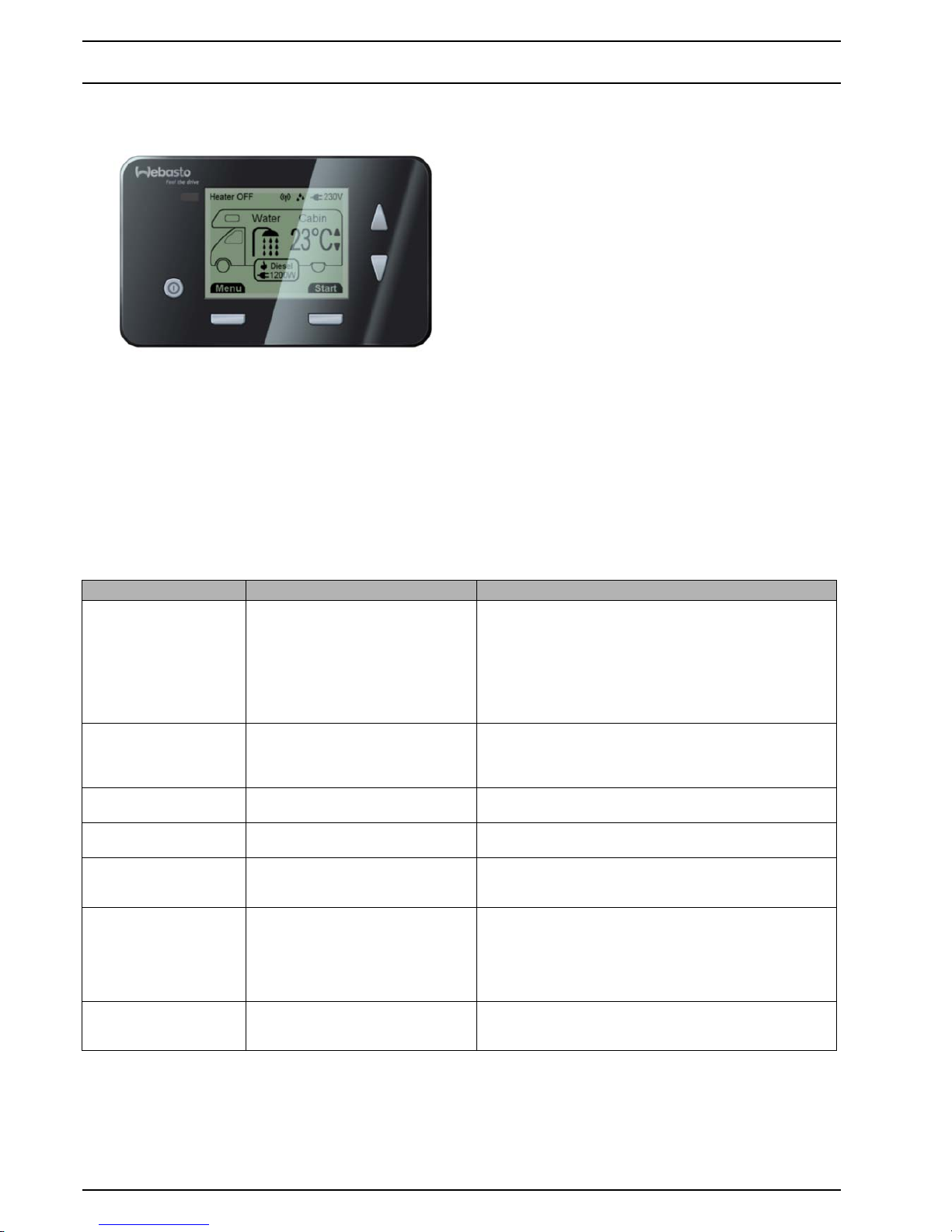
3.2 Programmable Control Panel
Fig. 303 Programmable Control Panel
The programable Control Panel can be used with all types
Dual Top heaters.
The heater is able to identify faults on individual
components and during the operation.
The Control Panel gives out the fault message.
Rectify the cause of the fault.
To reset the fault, confirm message by pressing OK (if
provided) or switch off the Dual Top for at least 5 seconds.
If serious malfunctions such as overheating or failure to start
reoccur, the heater is locked and can be put back into
service by deleting the failures.
Do this by disconnecting the power supply:
Ensure that the heater/ventilator is not running (to be
established by the sound of the heater operating).
If necessary wait until ventilators stop running.
Switch off Dual Top by pressing on/off button.
Remove all 3 fuses in this sequence: 5A, 10A, 15A; insert
the fuses in reversed order after at least 5 seconds.
Now the heater is reset.
Deleting failures can also be done with the Webasto Thermo
Test PC-Diagnosis.
If a fault occurs, the heater stops. Failure of drainage valve
(message 28 and 29) will not abort heater operation and will
not be shown during heater operation.
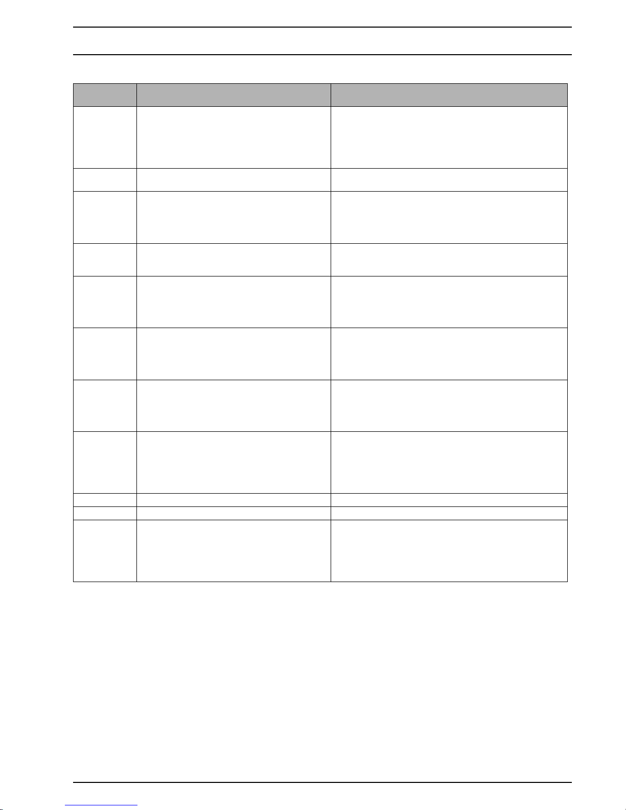
Table 302: Fault messages programmable Control Panel
Message Meaning Remedy
Message 01
No data connection
No communication between
Control Panel and heater, or error
Control Panel.
1 First, remove fuses 15A and 5A. Then put in fuse 15A,
followed by fuse 5A.
2 Check connections of Control Panel.
3 Check fuse 15A.
4 Check wiring harness.
5 Replace Control Panel (see chapter 6: "Servicing
work").
6 Replace control unit.
Message 02
No start of combustion
No start (after 2 attempts to start) 1 Check fuel supply (enough fuel, at least 8 ltr.; check
fuel connection and tubes), reset heater (by switching
off for at least 30 sec.).
2 Clean burner insert.
Message 03
Combustion interrupted
Flame failure. Restart not successful See message 02.
Message 04
High battery voltage
Operation voltage is above
permitted value
Reset heater (by pressing OK or switching off for at least
5 sec.)
Message 05
Low battery voltage
Operation voltage is below
permitted value
Charge battery or connect to main power supply (230V),
reset heater (by pressing OK or switching off for at least
5 sec.)
Message 06
Fuel pump disconnected
or system overheated
Fuel pump disconnection / one of
the three overheating switches
detects too high temperature
OR relaybox, cable or connection
relaybox is defective
1 Check fuel pump cable and connectors.
2 Check internal wiring harness connections Y9, Y10.
RHA 101/102 additionally:
1 Check wiring harness relaybox to heater.
2 Check relaybox and connections relaybox.
Message 07
Fuel pump short circuit
Fuel pump short circuit to ground
OR relaybox, cable or connection
relaybox is defective
See message 06.
Page 13
Dual Top 3 Fault code output
305
Message 08
Failure heating air
ventilator
Hot air motor fault: disconnection /
short circuit / fan speed out of range
/ fan blocked
1 Check power supply:
Fuse correct (fuse not damaged, 10A fuse used for
PWM module) and functioning.
All contacts are correct (no corrosion).
Voltage correct (>12V).
Restart heater.
2 Start blower: component test in diagnostic mode.
Run blower 5 minutes at 80%.
Listen if there is any unusual noise (grinding, etc.).
Restart heater.
3 Dismount application parts until the fan is visible.
Check if dirt, screws, objects or deformations block
the fan.
Check fan clearance with your finger (no high force!).
Remove all matters that block the fan.
Restart heater.
4 Remove service cap.
Check all electrical connectors.
Moisture in connectors (2-pin connector and 4-pin
connector)?
Moisture in connectors or on PWM module?
PWM module dark or burned?
12V power supply permanently available at PWM
module? (measure voltage between brown and red/
blue cable contacts of 4-pin connector) If not, check
external wiring harness: routing wiring harness and
pins of 12 pin connector.
In case there is a bad connector, bad wiring harness or
defect PWM module: replace defect part.
5 If heating air blower assy and wiring harness have
been checked and Dual Top still doesn’t run: replace
complete Dual Top.
Message 09
Failure ventilator
amplifier
No communication between
amplifier of heating air ventilator
and heaters control unit
1 Check internal cable routing (4-pins) from control unit
to PWM module.
2 Replace heating air blower assy.
3 Replace thermo unit.
Message 10
High temperature
sanitary water
Overheating water temperature
sensor
1 Check water level, reset heater (by pressing OK or
switching off for at least 5 sec.) or select winter mode
without hot water production.
2 Check fuel pump cable and connectors.
3 Check internal wiring harness connections Y9, Y10.
Message 11
High temperature
sanitary water
Exceeding gradient water
temperature sensor
1 See message 10.
2 Check if hot and cold water pipes have been
connected correctly.
Message 12
High temperature
heating air
Overheating hot air temperature
sensor
1 Ensure that hot air can flow freely, air intake and
outlets are not blocked.
Reset heater (by pressing OK or switching off for at
least 5 sec.)
2 Check fuel pump cable and connectors.
3 Check internal wiring harness connections Y9, Y10.
4 Check correct assembly of hot air temperature sensor.
Message 13
High temperature
heating air
Exceeding gradient hot air
temperature sensor
See message 12.
Message 14
Failure cooling air
ventilation
Overheating of heaters' control unit Ensure that cooling air can flow freely,
reset heater (by pressing OK or switching off for at least
5 sec.)
Message 15
Failure combustion air
motor
Combustion air motor interrupted 1 Ensure that cooling fan can freely rotate,
remove possible blocking objects.
2 Check fuse 15 A.
3 Check connector Y1 at control unit.
4 Change Drive Assy.
Message 16
Failure combustion air
motor
Combustion air motor fault:
disconnection / short circuit /
overload / blocked
See message 15.
Table 302: Fault messages programmable Control Panel
Message Meaning Remedy
Page 14
3 Fault code output Dual Top
306
Message 17
Failure control unit
Control unit (heater) fault / heater
locked
1 Put heater back into service (see above this table) and
restart heater.
2 Replace control unit.
Message 18
Failure cabin temperature
sensor
Interior temperature sensor
disconnection / short circuit
1 Check routing of cable, ensure that it is not pinched or
crushed,
check the connector behind the control panel.
Reset heater (by pressing OK or switching off for at
least 5 sec.)
2 Replace interior temperature sensor.
Message 19 n/a n/a
Message 20
Failure heating air
temperature sensor
Hot air temperature sensor
disconnection
1 Check routing of cable, ensure that it is not pinched or
crushed, check the connectors.
2 Check resistance of hot air temperature sensor.
3 Reset heater (by pressing OK or switching off for at
least 5 sec.)
4 Replace sensor wiring harness.
Message 21
Failure heating air
temperature sensor
Hot air temperature sensor short
circuit
See message 20.
Message 22
Failure sanitary water
temperature sensor
Water temperature sensor
disconnection
1 Check routing of cable, ensure that it is not pinched or
crushed, check the connectors.
2 Check resistance of water temperature sensor.
3 Reset heater (by pressing OK or switching off for at
least 5 sec.)
4 Replace sensor wiring harness.
Message 23
Failure sanitary water
temperature sensor
Water temperature sensor short
circuit
See message 22.
Message 24
Failure glow plug
Glow plug / flame detector
disconnection
1 Check routing of cable, ensure that it is not pinched or
crushed, check the connectors.
2 Check resistance of glowplug.
3 Reset heater (by pressing OK or switching off for at
least 5 sec.)
4 Replace burner (incl. glowplug and evaporator
housing assy).
Message 25
Failure glow plug
Glow plug / flame detector short
circuit
See message 24.
Message 26
Failure flame detection
Early flame detection See message 24.
Message 27
Failure relay box
Short circuit of 230V indication
signal from relay box to heater
1 Check wiring harness relaybox to heater.
2 Check the relay box and wiring connections.
3 Check Control Panel and connections Control Panel.
4 Check internal wiring harness connections Y9, Y10.
Message 28
Failure drain valve
Electrical drainage valve
disconnection
1 Check routing of cable, ensure that it is not pinched or
crushed, check the connectors.
2 Check function of valve with separate 12V DC power
supply.
3 Reset heater (by pressing OK or switching off for at
least 5 sec.)
4 Replace solenoid valve.
Message 29
Failure drain valve
Electrical drainage valve short circuit See message 28.
Message 30
Failure relay
230V high or low power relay circuit
interrupted / short circuit
See message 27.
Message 31, 32, 33 n/a n/a
Table 302: Fault messages programmable Control Panel
Message Meaning Remedy
Page 15
Dual Top 3 Fault code output
307
Note:
n/a = not available
Message 34
System overheated or
relay circuit disconnected
One of the three overheating
switches detects too high
temperatures / overheating relay
circuit interrupted
RHA 101/102:
1 Check wiring harness relaybox to heater.
2 Check the relay box and wiring connections.
3 Check Control Panel and connections Control Panel.
4 Check internal wiring harness connections Y9, Y10.
All:
1 Check for overheating (see messages 10, 11, 12, 13
and 14).
2 Reset heater (by pressing OK or switching off for at
least 5 sec.)
Message 35
Failure relay box
230V overheating relay short circuit See message 27.
Message
36, 37, 38, 39, 40, 41
n/a n/a
Message 42
Failure 230V heating
element
Electric heating device 230V defect.
No relevant temperature increase
detected.
1 Check water system for a permanent open hot water
tap OR heavy leakages.
2 Check cable 230V from relaybox to heater and
corresponding connectors.
3 Check electrical element heaters.
Table 302: Fault messages programmable Control Panel
Message Meaning Remedy
Page 16

3 Fault code output Dual Top
308
Page for notes
Page 17

Dual Top 4 Function tests
401
4 Function tests
4.1 General
This section describes the tests conducted on the heater
when it is installed and not installed to verify that it is in
working order.
WARNING
The heater must not be operated in enclosed areas such as
garages and workshops without an emissions extraction system.
4.2 Repair Shop Level Testing
4.2.1 Testing individual components
IMPORTANT
For function tests always break the connection between the
control unit and the component you wish to test.
4.2.1.1 Glowplug resistance test
NOTE
The resistance test must be carried out with an ohmmeter
suitable for small resistance values or Webasto Thermo Test
Diagnosis.
A resistance test with a simple digital multimeter is too inaccurate to find the precise values. A new glow plug can be
measured to act as a reference.
The glow plug should have the following values in the test:
Glow plug: 12 V (red)
Resistance at 25 °C: 0.190 ... 0.250 Ω
Test current: < 5 mA
4.2.1.2 Air temperature sensor resistance test
If you conduct this test with a digital multimeter the air temperature sensor must have the values shown in the following diagram:
4.2.1.3 Water temperature sensor resistance test
A: Resistance in kΩ
B: Temperature of water temperature sensor -G18- in °C
C: Resistance as a function of temperature
Resistance in Ohm
Temperature in °C
Characteristic resistance values of a PT 2000 overheating
sensor within a temperature range of 10 °C to 30 °C.
Table 401: Technical data water temperature sensor
Temperature
[°C]
Resistance
nominal
[Ohm]
Resistance
min.
[Ohm]
Resistance
max.
[Ohm]
-10 14.939,00 14.351,00 15.528,00
-5 11.425,00 10.991,00 11.859,00
0 8.816,00 8.493,00 9.138,00
5 6.855,00 6.613,00 7.097,00
10 5.373,00 5.190,00 5.556,00
15 4.241,00 4.102,00 4.379,00
20 3.372,00 3.266,00 3.479,00
25 2.700,00 2.619,00 2.781,00
30 2.175,00 2.107,00 2.244,00
35 1.763,00 1.706,00 1.821,00
40 1.438,00 1.390,00 1.487,00
45 1.180,00 1.139,00 1.220,00
50 972,80 938,10 1.008,00
55 806,30 776,80 835,80
60 671,80 646,60 697,00
65 562,40 540,80 584,00
70 473,00 454,50 491,60
75 400,00 383,90 416,00
80 339,70 325,80 353,60
85 289,50 277,50 301,60
90 247,80 237,30 258,30
Page 18

4 Function tests Dual Top
402
4.2.1.4 Air temperature switch
The air temperature switch opens at 145 ± 5 °C.
4.2.1.5 Water temperature switch
The water temperature switch opens at 90 ± 5 °C.
4.2.1.6 Overheating protector
The overheating protector (temperature switch heat exchanger) opens at 352 ± 15 °C and closes at 240 °C.
Fig. 401 Sensor positions
12
3
4
5
1 = Water temperature sensor
2 = Water temperature switch
3 = Air temperature switch
4 = Air temperature sensor
5 = Overheating protector
(temperature switch heat exchanger)
Page 19

Dual Top 5 Circuit diagrams
501
5 Circuit diagrams
5.1 General
Fig. 501 shows the heaters’ control unit.
How the electrical connections are to be made:
Fig. 502 for RHA 100,
Fig. 503 for RHA 101/102.
Electrical connections Control Panel:
Fig. 504 for manual version,
Fig. 505 for programmable version.
Circuit diagrams:
Fig. 506 for wiring harness RHA 100, older type,
Fig. 507 for external wiring harness RHA 100, newer type,
Fig. 508 for external wiring harness RHA 101/102,
Fig. 509 for internal wiring harness.
See Paragraph 5.2 for the legend of the circuit diagrams.
Fig. 501 Control unit Dual Top
Y1
Y3
Y2
Y7Y5Y4 Y6
Y1 = Combustion and cooling air blower connection
Y2 = Glowplug connection
Y3 = Air temperature switch connection
Y4 = Fuel pump connection
Y5 = Water temperature switch connection
Y6 = Status PWM (D+) connection
Y7 = Heater wiring harness connection
Page 20

5 Circuit diagrams Dual Top
502
Fig. 502 Schematical electrical connection Dual Top RHA 100
Fig. 503 Schematical electrical connection Dual Top RHA 101/102
1 Heater Dual Top
2 Wiring harness
3 Control Panel
4 Vehicle’s service battery
5Fuse 5A
6 Fuse 10 A
7 Fuse 15 A
8Fuel pump
9 Interior temperature sensor
10 Wiring interior temperature sensor
10
11
12
13
15
14
16
1 Heater Dual Top
2 Wiring harness
3 Control Panel
4 Vehicle’s service battery
5 Fuse 5 A
6 Fuse 10 A
7 Fuse 15 A
8Fuel pump
9 Interior temperature sensor
10 Wiring interior temperature sensor
11 Receiver Telestart / Thermo Call
(option)
12 Relay box
13 Wiring harness electric heater
14 Wiring 230 V
15 Power supply 230 V
16 Dashboard LED
Page 21

Dual Top 5 Circuit diagrams
503
Fig. 504 Electrical connections Manual Control Panel
Fig. 505 Electrical connections Programmable Control Panel
X0 (2 poles) of interior temperature sensor to Control Panel
X2 is for:
– Webasto Thermo Test PC-diagnosis and
– Webasto Telestart / Thermo Call (for optional programmable Control Panel).
X4 (4 poles) of wiring harness to Control Panel
X5
X0
X0 (2 poles) of interior temperature sensor to Control Panel
X2 is for:
– Webasto Thermo Test PC-diagnosis and
– Webasto Telestart / Thermo Call
X4 (4 poles) of wiring harness to Control Panel
X5 (6 poles) of wiring harness to Control Panel, 1 wire to dashboard LED
Page 22

5 Circuit diagrams Dual Top
504
Fig. 506 Wiring harness for Dual Top RHA 100 (older type, heater Ident. No. 9015314A and 9015314B)
X3
X4
X0
1
3
4
6
7
to heaters’ control unit
PC-diagnosis
Telestart
Thermo Call
Page 23

Dual Top 5 Circuit diagrams
505
Fig. 507 External wiring harness for Dual Top RHA 100 (newer type, heater Ident. No. 9015314C)
1
3
4
5
6
7
Page 24

5 Circuit diagrams Dual Top
506
Fig. 508 External wiring harness for Dual Top RHA 101/102
X3
5
6
X5
X6
567
8
X0
X1
X1
X12
4
Not in scope of delivery!
1
2
to X5
8
3
4
5
6
7
to 8
Page 25

Dual Top 5 Circuit diagrams
507
Fig. 509 Internal wiring harness for Dual Top RHA 100/101/102
Y7
X3
gn
rt
br
rt/bl
ge/rt
ge
sw
or
sw/ws
vi
gn
gn
rt/bl
br
gr
br
sw
gr
vi
gn
gn
ge
gr
or
gr
vi
or
Y11
Y8
Y12
Y9
Y10
Y6
Y4
Y5
Y3
br
gn
rt
br
ge/rt
ge
gr
gn
sw/ws
gn
ge
gr
or
4
Vehicle side
Vehicle side
Page 26

5 Circuit diagrams Dual Top
508
5.2 Legend for circuit diagram
1 Wiring harness vehicle
2 Wiring harness electric heater (not for RHA 100)
3 Vehicle’s service battery
4 Fuse 15 A
5 Fuse 10 A
6 Fuse 5 A
7 Interior temperature sensor
8 Dashboard LED (not for RHA 100)
Item Description Comment
X0 Plug connector, 2-pin To Control Panel (interior temperature sensor)
X1 Plug connector, 2-pin 2 pcs, to electric heater inside Dual Top (not for RHA 100)
X2 Plug connector, 4-pin To PC-diagnosis / Telestart / Thermo Call
X3 Plug connector, 2-pin To fuel pump
X4 Plug connector, 4-pin To Control Panel
X5 Plug connector, 6-pin To Control Panel, 1 wire to dashboard LED (not for RHA 100)
X6 Plug connector, 8-pin To relay box (not for RHA 100)
X11 Plug connector, 12-pin To heater Dual Top
X12 Wire end 4 pcs to relay box, 1 to ground (not for RHA 100)
Y3 Plug connector, 2-pin Air temperature switch; to control unit; marking “A” (blue)
Y4 Plug connector, 2-pin Fuel pump; to control unit; marking “C”
Y5 Plug connector, 2-pin Water temperature switch; to control unit; marking “B”
Y6 Plug connector, 2-pin Status PWM (D+) connection; to control unit; marking “A”
Y7 Plug connector, 12-pin To external wiring harness; to control unit
Y8 Plug connector, 4-pin To PWM module
Y9 Plug connector, 1-pin To temperature switch heat exchanger
Y10 Plug connector, 9-pin To water temperature switch, air temperature switch,
water temperature sensor, air temperature sensor
Y11 Plug connector, 12-pin To external wiring harness
Y12 Plug connector, 1-pin 2 pcs, to solenoid valve
Cable cross-sections
< 7.5 m 7,5 - 15 m
0.75 mm
2
1.0 mm
2
1.0 mm
2
1.5 mm
2
1.5 mm
2
2.5 mm
2
2.5 mm
2
4.0 mm
2
4.0 mm
2
6.0 mm
2
Cable colours
bl
br
ge
gn
gr
or
rt
sw
vi
ws
blue
brown
yellow
green
grey
orange
red
black
violet
white
Page 27

Dual Top 6 Servicing work
601
6Servicing work
6.1 General
This section describes the servicing work that can be carried
out on the heater when it is installed.
WARNING
There is a potential danger of burns as the heater and its
components may be very hot.
6.2 Work on the heater
Disconnect the main power cable from the service battery
before carrying out any work on the heater. The battery
power must not be disconnected whilst the heater is operating or slowing down as a result of the risk of the heater
overheating and the overheating guard thus being tripped.
If you wish to carry out extensive repair work on the heater,
it may be a good idea to remove it completely.
Refer to the relevant installation instructions for repairs that
necessitate the installation position being changed.
6.3 Work on the vehicle
IMPORTANT
A temperature of 85 °C must not be exceeded in the vicinity
of the heater in any circumstances (for example when competing painting work on the vehicle).
6.4 Heater test run
WARNING
The heater must not be operated in enclosed areas such as
garages and workshops without an emissions extraction system.
6.5 Servicing work
To ensure functional reliability of the heater the following
servicing must be performed in regular intervals:
• the heater must be switched "OFF" before cleaning.
• clean heater exterior (do not use high-pressure water or
air hoses, prevent the ingress of water).
• examine electrical connections for corrosion of contacts
and to ensure that they are secure.
• check the following lines for signs of damage, to ensure
that they are secure and clear:
- exhaust,
- combustion air,
- cooling air,
- heating air intake and
- hot air distribution.
IMPORTANT
Some parts of the system, especially the exhaust, may
have a shorter life than the heater itself. Especially if the
vehicle is used in areas with salty conditions, like near
seas and oceans. Pay extra attention to these parts and
replace them if necessary.
• inspect fuel lines for leaks.
• check cold and hot water lines for signs of damage and
to ensure that they are secure.
• inspect hoses for cracks.
• check the manual drainage function with the Control
Panel.
6.6 Visual inspections and installation
instructions
Check if the whole application is installed in accordance
with the Installation Instructions.
6.7 Removal and installation
IMPORTANT
When the heater is installed it must not be dismantled.
6.7.1 Heater, removal and installation
6.7.1.1 Removal
1. Drain water contents.
2. Disconnect the battery.
3. Disconnect the wiring harness plug X11.
4. Disconnect the cable to the fuel pump at plug X3.
5. Disconnect from the heater:
- hot air hoses,
- exhaust pipe,
- combustion air line,
- cooling air hose,
- heating air intake line,
- fuel line (close with suitable plug or any other means),
- hot and cold water lines.
6. Remove four M8 nuts from the hammerhead bolts.
7. Remove the heater.
Page 28

6 Servicing work Dual Top
602
6.7.1.2 Installation
See Installation Instructions.
6.7.2 Control Panel, removal and installation
6.7.2.1 Manual version (for RHA 100)
1. Disconnect the battery.
2. Remove Control Panel as shown (see Fig. 601).
3. Disconnect the wiring harness plug X11.
4. Disconnect plug X0 of the interior temperature sensor.
Fig. 601 Manual Control Panel (dis)assembly
6.7.2.2 Programmable version (for RHA 100/101/102)
1. Disconnect the battery.
2. Remove Control Panel:
Place 1 or 2 suction cups on the Control Panel.
Alternatively, slide flat, smooth material (e.g. plastic
card) under the control panel at the left and right hand
side.
Pull to remove the Control Panel out of the adapter.
Careful: do not damage Control Panel or furniture.
See Fig. 602.
3. Disconnect the wiring harness plugs X4 and X5.
4. Disconnect plug X0 of the interior temperature sensor.
Fig. 602 Programmable Control Panel (dis)assembly
6.7.2.3 Installation
See Installation Instructions.
6.8 Start-up
After each heater disassembly, follow the procedure "Starting the heater for the first time", as described in the Installation Instructions.
Page 29

Dual Top 7 Repair
701
7Repair
7.1 General
This section describes the repair work that may be carried
out on the Dual Top heater after it has been removed from
the vehicle.
Any further disassembly will void the warranty.
Only use the spare parts from the appropriate spare parts
kits for assembling the heater.
After repairs a functional test shall be performed.
7.1.1 Work on dismantled components
IMPORTANT
All sealing elements between the stripped down components and the seal on the exhaust outlet shall always be discarded and replaced.
7.1.1.1 Cleaning
• All components disassembled shall be cleaned.
• Sealing compound on components must be carefully
and completely removed using suitable means.
7.1.1.2 Visual inspection
• Check all components for damage (cracks, deformation,
wear, etc.) and fit new ones if necessary.
• Inspect the plugs and cables for corrosion, loose contacts, crimping faults, etc. and repair them if necessary.
• Check plug strips for signs of corrosion and contacts to
ensure they are secure.
Repair them if necessary.
7.2 Dismantling
Loosen 2 screws T20 below hot and cold water connectors
1 ~ 2 turns (just enough to move cover heating air blower).
Loosen 8 screws T25 to remove service cap.
NOTE
When removing service cap, friction is caused by the grommet on the two water pipes.
Page 30

7 Repair Dual Top
702
Remove foam gasket cooling shell and air intake grill.
Loosen 8 screws T25 to remove end cap incl. seal end cap
boiler.
NOTE
Loosen 2 screws T20 that hold metal plate (with air temperature sensor and air temperature switch) of sensor wiring
harness to end cap.
Loosen 2 screws T30 of heating air blower assy with PWM
module.
Pull plug 4 poles of wiring harness out of PWM module (at
side of motor heating air blower assy).
Remove heating air blower assy.
NOTE
Do NOT take air blower assy / PWM module apart!
Once disassembled, distance between speed sensor and
magnet on blower cannot be guaranteed.
Air blower assy is sold as complete unit.
For RHA 101/102 only:
Loosen screw T30 and hex nut SW 10 mm to remove
green/yellow ground wire from housing.
Page 31

Dual Top 7 Repair
703
Loosen 4 screws T30 on bottom of Dual Top.
Push boiler incl. insulation out of housing.
Remove 2 parts insulation.
Remove drain tube from air ventilation/overpressure valve,
solenoid valve and cooling air outlet.
Pull 2 plugs 1 pole out of solenoid valve.
Remove insulation combi-valve (top) and solenoid valve
(bottom).
Use flat (-) screwdriver to push down ring below solenoid
valve and pull valve up to remove it from boiler.
IMPORTANT
Avoid that screwdriver makes scratches on tube.
Scratches will cause leakage. Alternative: use plastic tool.
Page 32

7 Repair Dual Top
704
Use flat (-) screwdriver to push down ring of connector hot
and cold water pipes and pull pipes up to remove them from
boiler.
In the same way, remove air ventilation/overpressure valve.
IMPORTANT
Avoid that screwdriver makes scratches on tubes.
Scratches will cause leakage. Alternative: use plastic tool.
Loosen 4 screws T30 that attach thermo unit to boiler.
Remove thermo unit incl. heat exchanger.
Backside boiler: loosen hex nut SW 7mm that attaches water temperature switch and water temperature sensor of
sensor wiring harness to backside boiler.
Remove sensor wiring harness and pink coloured silicon
pad.
Disconnect plug 8 poles of sensor wiring harness from internal wiring harness.
Remove 4 springs from backside of the heat exchanger.
Page 33

Dual Top 7 Repair
705
Loosen 2 screws T10 that hold overheat switch to backside
heat exchanger.
Remove wires and cable fasteners from the ribs on the heat
exchanger.
Disconnect plug 2 poles of wiring overheating protector
from internal wiring harness.
For RHA 101/102 only:
Disconnect 2 plugs X1 (2 poles, 1x grey and black, 1x
brown and blue) of wiring from relay box to tubular
heaters.
Loosen screw T10 at backside of heat exchanger to remove holding plate coil.
Pull tubular heaters backwards to take them out of heat
exchanger.
Remove exhaust gasket from exhaust and cooling air outlet.
Loosen 8 screws T20 to remove cooling shell.
NOTE
- small rubber: fuel line
- large rubber: wiring harness
Page 34

7 Repair Dual Top
706
Disconnect 5 plugs of internal wiring harness from control
unit.
Loosen screw T20 that attaches brown wire to control unit.
Remove internal wiring harness.
Disconnect 2 remaining plugs 2 poles and loosen second
screw T20 to remove control unit from thermo unit.
Control unit:
1 = Temperature sensor control unit
2 = Hall sensor for cooling/combustion air fan speed
Remove gasket cooling shell.
Loosen 8 screws T20 to remove drive assy from heat exchanger.
Remove flat gasket heat exchanger.
Loosen 3 screws T20 to remove combustion air intake incl.
connection gasket from drive assy.
br
1
2
Page 35

Dual Top 7 Repair
707
Loosen 2 screws T20 to remove clamping yoke from heat
exchanger.
Press grommet of wire glowplug inwards and guide plug
through hole heat exchanger.
Press grommet of fuel line inwards.
Remove evaporator housing assy with fuel line and glowplug from heat echanger.
Pull holding spring glowplug to remove glowplug from
evaporator housing assy.
Loosen 2 screws T20 to remove burner tube assy and metal
crimp sealing from heat exchanger.
Page 36

7 Repair Dual Top
708
7.3 Assembling
Align straight sides of burner tube assy and metal crimp
sealing with bottom of heat exchanger.
Fix with 2 screws T20.
NOTE
Position screws see drawing.
NOTE
Gaskets must always be renewed.
Guide glowplug into evaporator housing assy and fix with
holding spring.
Guide fuel line from inside to outside through large hole in
bottom of heat exchanger.
Place evaporator housing assy in of burner tube assy.
Press grommet fuel line in hole heat exchanger.
Guide wiring glowplug from inside to outside through small
hole in side of heat exchanger.
Press grommet of wire glowplug in hole heat exchanger.
Fix evaporator housing assy to heat exchanger with clamping yoke and 2 screws T20.
Fix combustion air intake incl. connection gasket to drive
assy with 3 screws T20.
Page 37

Dual Top 7 Repair
709
Attach flat gasket heat exchanger and drive assy to heat exchanger and fix with 8 screws T20.
NOTE
Align 2 holes in gasket with protrusions on the heat exchanger.
Put gasket cooling shell on the heat exchanger.
NOTE
Align 2 holes in gasket with protrusions on the heat exchanger.
Connect 2 plugs from thermo unit (Y1 and Y2, see Fig. 501)
and 5 plugs of internal wiring harness (Y3, Y4, Y5, Y6 and
Y7, see Fig. 501) to control unit.
Put control unit on drive assy and fix with 2 screw T20.
Use 1 of these screws to fix brown wire.
Attach cooling shell to heat exchanger with 8 screws T20.
Note:
- small rubber between cooling shell and fuel line
- large rubber between cooling shell and wiring harness
br
1
2
Page 38

7 Repair Dual Top
710
Put gasket exhaust on exhaust and cooling air outlet.
For RHA 101/102 only:
Slide electrical element from backside into the heat exchanger.
NOTE
Correct position of the electrical element.
Fix tubular heaters to heat exchanger with holding plate
coil and screw T10.
Connect 2 plugs X1 (2 poles, 1x grey and black, 1x
brown and blue) of wiring elements to wiring from relay
box.
Fix overheating protector to backside heat exchanger
with 2 screws T10.
Connect plug 2 poles of wiring overheating protector to
internal wiring harness.
Fix wires to ribs heat exchanger using cable fasteners.
Put 4 springs on heat exchanger to assure that clearance between heat exchanger and boiler is spread evenly.
Page 39

Dual Top 7 Repair
711
Connect plug 8 poles of sensor wiring harness to internal
wiring harness.
Put pink coloured silicon pad on 2 threaded studs M4 at
backside boiler and fix water temperature switch and water
temperature sensor of sensor wiring harness with hex nut
SW 7mm.
NOTE
Renew pink coloured silicon pad every time you replace the
sensor wiring harness. This is important for good heat conduction.
Put thermo unit into boiler and fix with 4 screws T30.
NOTE
Make sure that clearance between heat exchanger and boiler is spread evenly. For this purpose, the thermo unit has
large holes.
Push air ventilation/overpressure valve as far as possible on
connection of boiler.
Push hot water pipe as far as posible into air ventilation/
overpressure valve and cold water pipe into connection of
boiler.
Push solenoid valve as far as posible into connection of boiler.
Page 40

7 Repair Dual Top
712
Attach self-adhesive insulation combi-valve (top) and solenoid valve (bottom).
NOTE
Make sure that it’s possible to connect drain tube and wiring to valves.
Connect 2 plugs 1 pole with solenoid valve.
Use 2 parallel poles of valve.
Doesn’t matter which wire colour is connected to which
pole (upper or lower).
Connect drain tube to air ventilation/overpressure valve and
solenoid valve.
Put open end in cooling air outlet.
Put 2 parts insulation on top and bottom of Dual Top (parts
are identical).
NOTE
– Arrows on insulation have to point backwards.
– Put sensor wiring harness between bottom of boiler and
lower part insulation (groove in insulation).
Carefully push Dual Top incl. insulation into housing.
NOTE
Housing Dual Top shall fit into groove of gasket exhaust.
Fix boiler to housing with 4 screws T30 on bottom of
Dual Top.
For RHA 101/102 only:
Fix green/yellow ground wire to housing with screw T30
and hex nut SW 10 mm.
Tightening torque: 9 ± 0.9 Nm.
Page 41

Dual Top 7 Repair
713
Connect plug 4 poles of internal wiring harness to PWM
module.
Attach heating air blower assy to housing Dual Top with 2
screws T30.
NOTE
– Do not tighten screws yet!
– Make sure that wires don’t touch rotating parts.
Fix hold metal plate (with air temperature sensor and air
temperature switch) of sensor wiring harness to end cap
with 2 screws T20.
NOTE
Sensor and switch shall face towards end cap, not towards
heat exchanger.
NOTE
Overheating protector on heat exchanger shall not touch
metal plate (with air temperature sensor and air temperature switch) of sensor wiring harness.
Distance
≥
2mm.
NOTE
Put seal end cap around flange at backside of boiler.
Seal end cap is important to avoid air leakages.
Place this part correctly!
Fix end cap to housing Dual Top with 8 screws T25.
Tightening torque: 6 Nm.
Page 42

7 Repair Dual Top
714
Place foam gasket cooling shell and air intake fence.
Push spout water expiration into service cap.
Service cap shall fit into groove of spout.
Guide connectors water pipes through spout.
Fix service cap to Dual Top with 8 screws T25.
Tightening torque: 6 Nm.
NOTE
Service cap shall fit into grooves of grommets for wiring harnesses (1 pcs for RHA 100).
Position cover heating air blower and heating air blower
assy in such a way that heating air blower can rotate freely.
Then tighten 2 screws T20 (2 Nm) of cover heating air blower and 2 screws T30 (9 Nm) that fix heating air blower assy
to Dual Top housing.
NOTE
Check that the heating air blower rotates freely before placing heater back into vehicle.
Use Webasto Thermo Test’s component test to run heating
air blower with at 30, 60 and 90% for at least 30 seconds
in each level.
Page 43

Dual Top 7 Repair
715
7.4 Replacement of older to newer type Dual Top RHA 100
Webasto recommends the following procedure when older
types heaters Dual Top RHA 100 are completely replaced by
newer types.
Because the external wiring harnesses are not compatible, a
new type harness has to be used.
Older type Dual Top RHA 100 heaters have the following
Ident. No. (see model plate on heater): 9015314A and
9015314B.
Newer type Dual Top RHA 100 heaters (produced after June
2008) have Ident. No. 9015314C
Procedure:
1 Disconnect heater’s 12V power supply from battery.
2 Disconnect wiring harness from fuel pump.
3 Cut old wiring harness as close as possible to heat ex-
changer of Dual Top.
4 Cut new external wiring harness at approx. 25 cm dis-
tance from 12-pin plug. See Fig. 701.
5 Connect 25 cm of new external wiring harness with 12-
pin plug to old wiring harness (see Table 701 and Fig.
702).
Use watertight connectors.
6 Secure cables for fuel pump of old wiring harness (or-
ange and green/white cables).
7 Connect new internal wiring harness to fuel pump.
Fig. 701 Cut new external wiring harness
Fig. 702 Connect new 12-pin plug with old wiring harness
Table 701 Connecting cables
Old wiring harness New wiring harness
Red 2.5 mm
2
Red 2.5 mm2
Red 1.5 mm
2
Red/black 2.5 mm2
Brown 2.5 mm
2
Brown 2.5 mm2
Yellow 0.75 mm
2
Yellow 0.75 mm2
Black 0.75 mm
2
Black 0.75 mm2
Yellow/blue 0.75 mm
2
(or yellow/grey)
Yellow/red 0.75 mm2
25 cm
rt
rt/sw
br
ge
sw
ge/rt
rt
or
gn/ws
rt
br
ge
sw
ge/bl
Old fuel pump connection
12-pin plug to internal wiring
harness new heater
Old wiring harness in
vehicle
Page 44

7 Repair Dual Top
716
Page for notes
Page 45

Dual Top 8 Packaging, storage and shipping
801
8 Packaging, storage and shipping
8.1 General
If the heater or its components are sent to Webasto AG for
testing or repair, it must be cleaned and packed in such a
way that it is protected against damage during handling,
transport and storage.
An ambient temperature of +85 °C or -40 °C must not be
exceeded for storage.
IMPORTANT
Fully drain a complete heater before sending it back.
Make sure that no fuel or other liquid can leak out during
packing and/or shipment.
Seal the ports with dummy plugs.
Page 46

8 Packaging, storage and shipping Dual Top
802
Page for notes
Page 47

Page 48

Webasto AG
Kraillinger Strasse 5
82131 Stockdorf
GERMANY
http://dealers.webasto.com
http://www.webasto.com
Subject to modification
© 2009 All Rights Reserved
IDENT.-NR. 9019782B
 Loading...