

Page 1
Operating instructions
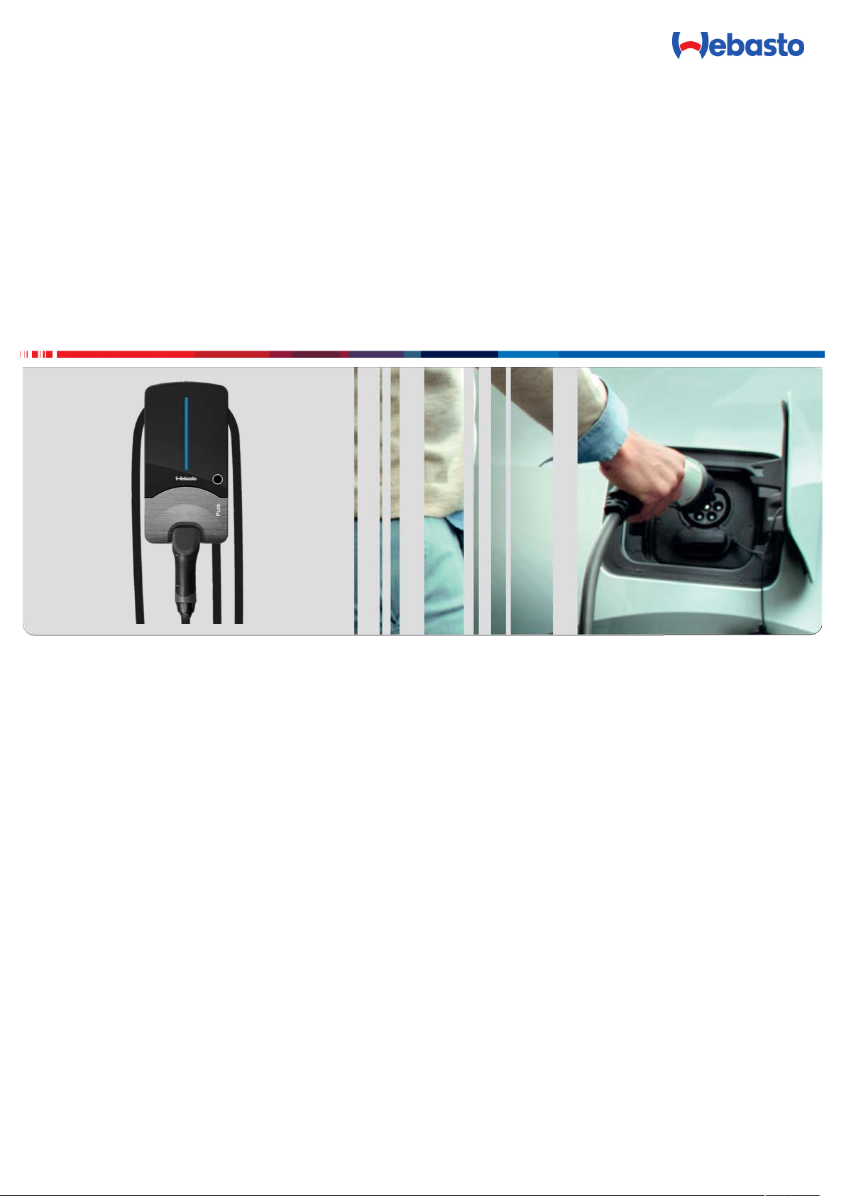
Webasto Pure
English
Page 2

Table of Contents
Table of Contents
1 General information............................ 3
1.1 Purpose of the document ..........................................3
1.2 Using this document.................................................. 3
1.3 Intended use ............................................................. 3
1.4 Use of symbols and highlighting ................................ 3
1.5 Warranty and liability................................................. 3
2 Safety .................................................3
2.1 General information ..................................................3
2.2 General safety information ........................................3
2.3 Safety information for installation..............................4
2.4 Safety information for electrical connection...............4
2.5 Safety information for initial start-up .........................4
3 Operation ...........................................4
3.1 overview.................................................................... 4
3.2 LED indicators............................................................ 4
3.3 Touch control switch (reset)....................................... 5
3.4 Key-operated switch..................................................5
3.5 Start charging............................................................ 6
3.6 Stop charging............................................................ 6
4 Settings ..............................................6
4.1 To activate programming mode................................. 6
4.2 Dim LED indicator (option 1)......................................6
5 Decommissioning the product ............ 7
6 Maintenance, cleaning, repair ............ 7
6.1 Maintenance .............................................................7
6.2 Cleaning .................................................................... 7
6.3 Repair........................................................................7
7 To replace the charging cable.............7
8 Disposal .............................................. 7
9 Declaration of conformity................... 7
10 Technical data ....................................8
2 OI Webasto Pure A4 EN
Page 3
General information | 1
1 General information
1.1 Purpose of the document
These operating and installation instructions are part of the
product and contain information for the user to ensure safe operation and for the electrician to carry out safe installation of
the Webasto Pure charging station.
1.2 Using this document
u
Carefully read the operating and installation instructions before installing and starting up the Webasto Pure.
u
Keep these instructions ready to hand.
u
Hand these instructions on to the following owner or user
of the charging station.
1.3 Intended use
The Webasto Pure charging station is designed for charging
electric vehicles in accordance with IEC 61851-1, charge mode
3. In this charge mode, the charging station ensures:
n The voltage is not applied before the vehicle has been con-
nected correctly.
n The maximum power is calibrated.
The AC/DC converter is in the vehicle.
1.4 Use of symbols and highlighting
DANGER
This signal word denotes a hazard with a high degree
of risk which, if not avoided, will lead to death or serious injury.
WARNING
This signal word denotes a hazard with a moderate degree of risk which, if not avoided, may lead to minor or
moderate injury.
CAUTION
This signal word denotes a hazard with a low degree of
risk which, if not avoided, will lead to minor or moderate injury.
NOTE
This signal word denotes a Special Technical Feature or
(if not observed) potential damage to the product.
Refers to separate documents which are enclosed or
can be requested from Webasto.
Symbol Explanation
Requirements for the following necessary action
Necessary action
1.5 Warranty and liability
Webasto shall not assume liability for defects or damage that
are the result of the installation and operating instructions being
disregarded. In particular, this liability exclusion applies in the
following cases:
n Improper use.
n Use of non-original spare parts.
n Installation and commissioning carried out by unqualified
staff (not an electrician).
n Modification of the device without observing Webasto re-
pair instructions.
2 Safety
2.1 General information
The charging station has been developed, produced, tested and
documented according to the relevant safety regulations and
environmental requirements. The device must only be used in a
technically faultless condition.
Have any malfunctions that adversely affect the safety of persons or of the device rectified immediately by an electrician in
accordance with nationally applicable regulations.
NOTE
It is possible that the signalling in the vehicle differs
from that described here. Always read the operating instructions of the respective vehicle manufacturer and always observe these.
2.2 General safety information
n Hazardous voltages are present within the casing.
n The charging station does not have its own main ON/
OFF switch. The protective devices installed in the
power supply system are therefore also used to disconnect the power supply.
n Check charging station for visual damage before use.
Do not use the charging station if damaged.
n Installation, electrical connection and initial operation
of the charging station must only be carried out by an
electrician.
n Do not remove the cover of the installation area whilst
in operation.
n Do not remove markings, warning symbols and the
type label from the charging station.
n The charging cable must only be replaced by an elec-
trician in accordance with the installation instructions.
n It is strictly prohibited to connect other equipment/
devices to the charging station.
n When not in use, store the charging cable in the des-
ignated holder and lock the charging coupling in the
charging station. Loosely wind the charging cable
around the charger casing so that it does not touch
the ground.
n Make sure that the charging cable and coupling can-
not be driven over, trapped and are protected from
any other hazards.
n Immediately notify Webasto Customer Service if the
charging station, charging cable or the charging coupling are damaged. Do not continue using the charging
station.
n Prevent the charging cable and coupling from coming
in contact with external heat sources, water, dirt and
chemicals.
n Do not attach extension cables or adapters to the
charging cable.
n Remove the charging cable by pulling on the charging
coupling only.
n Never clean the charging station with a high-pressure
cleaner or similar device.
n Switch off the power supply before cleaning the char-
ging sockets.
n When using the charging cable, please ensure that the
maximum permitted force of 39N (for 11kW) and
48N (for 22kW) is not exceeded.
n Ensure only persons who have read these operating
instructions have access to the charging station.
OI Webasto Pure A4 EN 3 / 9
Page 4

3 | Operation
WCH000007A
WCH000005A
2.3 Safety information for installation
n Installation and connection of the charging station
must only be carried out by an electrician.
n Only use the supplied installation material.
n The Webasto Pure safety concept is based on a power
supply system that is earthed at all times. The electrician must ensure this requirement during installation.
n The charging station is suitable for use in areas without
access restrictions.
n Do not install the charging station in an explosion
sensitive area (EX zone).
n Install the charging station in such a way that the char-
ging cable does not block any passageways.
n Do not install the charging station in areas subject to
ammonia or air containing ammonia.
n Do not install the charging station in a location where
falling objects (e.g. extension reel or tyres) can damage
the charging station.
n The charging station is designed for use indoors, e.g.
garages as well as for use in protected outdoor areas,
e.g. carports. Do not install the charging station in the
vicinity of water jets, e.g. car wash installations, high
pressure cleaners or garden hoses.
n The charging station shall not be exposed to direct rain
to prevent damage due to freezing, hail or similar.
n Protect the charging station from direct sunlight. The
charging current may be reduced at high temperatures
or charging may be disabled completely.
n The installation location of the charging station should
be selected such that vehicles cannot inadvertently collide with it. Protective measures must be implemented
if the possibility of damage cannot be ruled out.
n Do not place the charging station into operation if it is
damaged during installation. A replacement will be required.
2.4 Safety information for electrical connection
n Comply with the nationally applicable requirements
pertaining to electrical installations, fire protection,
safety regulations and escape routes at the intended
installation location. Observe the applicable national
installation regulations.
n Each charging station must be protected with its own
line circuit breaker and residual current circuit breaker.
See Requirements at the installation location.
n Make sure that the electrical connections are de-ener-
gised before connecting the charging station to the
power supply.
n Do not connect a vehicle during initial start-up of the
charger.
n Make sure that the correct supply cable is used for the
power connection.
n Do not leave the charging station unattended with the
cover open.
n Do not install the charging station without the mount-
ing frame.
n Change DIP-switch settings only with the power off.
n Register with the power supply company as required.
2.5 Safety information for initial startup
n Initial start-up of the charging station must be carried
out only by an electrician.
n Prior to initial start-up, the electrician must check that
the charging station has been connected correctly.
n Before starting-up the charging station, check the
charging cable, charging coupling and the charging
station for visible damage. The charging station must
not be started up if it is damaged or if the charging
cable/charging coupling is damaged.
3 Operation
3.1 overview
Fig.1
Legend
1 LED indicator 4 Charging coupling holder
2 Touch control switch 5 Key-operated switch, ac-
cessible from below
3 Charging cable holder 6 Installation cover
3.2 LED indicators
Fig.2
Legend
N1 … N5 LED operating indicator
F1 … F6 LED fault list
4 / 9 OI Webasto Pure A4 EN
Page 5

Operation | 3
WCH000008A
t [s] Time [s]
3.2.1 LED-colours
LED-colours
Blue Stand by
Green Charging
Red Faults
Yellow Temperature limit
Purple Charging current limit activated (20 A for 1-phase
Light blue Charging current limit deactivated
White Programming mode
Description
charging)
3.2.2 LED operating indicator
Operating indicator
N1 LED flashes red/green/blue at 1 second intervals:
N2 LED is blue:
N3 LED is green:
N4 LED flashes blue at 1 second intervals:
N5 LED flashes for half a second at 5 second intervals:
Description
Charging station is starting.
Charging station in standby mode; charging station
can be used.
Charging station being used; charging vehicle.
Charging coupling connected to the vehicle, charging complete or charging temporarily interrupted.
The charging station is in operation but locked with
the key-operated switch.
3.2.3 LED fault list
Fault list Description
F1 LED is yellow for 1 s and green for 2 s:
The charging station has become hot and charges
the vehicle with reduced power. After a cool-down
phase the charging station continues the normal
charging cycle.
F2 LED is yellow:
Excess temperature. Charging stopped due to high
temperature within the charger. After a cool-down
phase the charging station continues the normal
charging cycle.
F3 LED is red and a buzzer sounds for 28s and then
for 2s every 10 minutes:
There is a problem in the voltage or system monitoring.
DANGER
Danger of fatal electric shock.
u
Switch off and secure the power supply to the
charging station. Only then unplug the cable from
the vehicle.
u
Contact the Webasto Charging Hotline at
00800-24274464.
Fault list Description
F4 LED is red for 1s and green for 2s:
Fault list Description
There is a fault in the power connection to the
charging station, phase monitoring is active, charging station charges with reduced power.
u
Checking of the rotary field by an authorised
electrician.
F5 LED flashes red for 1s at 2s intervals, a signal
sounds for 28s and then for 2s every 10 minutes:
There is a fault in the vehicle.
u
Re-connect the vehicle
NOTE
If the warning persists, contact Webasto Charging Hotline under 00800-24274464.
Fault list Description
F6 LED flashes red for 0.5s at 0.5s and 3s intervals:
the supply voltage is outside the valid range of 180
V to 270 V.
u
Checking by an authorised electrician.
3.3 Touch control switch (reset)
NOTE
Do not press but only touch the touch control switch,
do not wear gloves when operating.
The touch control switch is used to acknowledge faults.
Action Description
u
Touch and hold the switch
for at least 10s.
Starts a system self-test and resets failures. After the fault has
been rectified, the charging
station switches back to
"standby" mode.
3.4 Key-operated switch
The key-operated switch is used for authorisation purposes and
can be turned through 90°. Turn clockwise to unlock the charging station. Turn anticlockwise to lock the charging station.
Fig.3
NOTE
The key can be removed in both positions.
OI Webasto Pure A4 EN 5 / 9
Page 6

4 | Settings
WCH000006A
3.5 Start charging
NOTE
Always take into account the vehicle requirements before charging a vehicle.
NOTE
Park the vehicle for charging such as to avoid strain in
the charging cable.
Fig.4
Action Description
u
Connect the
charging
coupling to
the vehicle.
Charging station performs system and connection tests.
LED: is blue, turns red for about 2 seconds
after connecting to the vehicle and then
either turns green (vehicle is charging) or
flashes blue (vehicle not yet ready for charging).
3.6 Stop charging
3.6.1 The vehicle has stopped the charging cycle automatically
Action Description
u
Unlock the car if necessary.
u
Unplug the charging coupling from the
vehicle.
u
Lock charging coupling in the holder of
the charging station.
3.6.2 If the vehicle does not automatically stop the charging cycle
Action Description
u
Set key-operated switch to
"OFF" position.
Or
u
Stop charging
cycle at vehicle.
Charging cycle is stopped. LED changes
to blue and flashes at 5 second intervals.
See chapter3.2, "LED indicators" on page
4, operating status N5.
Charging cycle is stopped. LED changes
to blue and flashes at 1 second intervals.
See chapter3.2, "LED indicators" on page
4, operating status N4.
LED flashes blue
at 1 second intervals. Vehicle
connected, not
charging.
4 Settings
NOTE
It is necessary to complete the following procedures
within a certain time, therefore read through all the
steps before starting the procedure.
4.1 To activate programming mode
See also chapter3.4, "Key-operated switch" on page 5.
ü Charging station switched on.
ü LED indicator is blue.
ü Key-operated switch set to ON.
ü No vehicle connected.
u
Set key-operated switch from ON to OFF, wait until LED indicator flashes blue 3 times.
u
Set key-operated switch from OFF to ON (for max. 3
seconds).
u
Set key-operated switch from ON to OFF; wait until LED indicator flashes blue once.
u
Set key-operated switch from OFF to ON (for max. 3
seconds).
u
Set key-operated switch from ON to OFF; wait until LED indicator flashes blue 3 times.
– When the LED indicator flashes for the fourth time it
changes to white and the charging station automatically
assumes programming mode.
Programming mode activated
The charging station runs through two options 10 times. If no
option is selected with the key-operated switch after the charging station has run through them 10 times, programming
mode will be deactivated automatically without any changes.
4.2 Dim LED indicator (option 1)
NOTE
The LED colours blue and green can be dimmed. The
brightness of the red warning colour can not be
changed.
Programming mode activated:
The LED indicator flashes white in the following sequence once:
– 0.5s OFF;
– 0.5s ON;
After a four second pause the LED indicator switches to yellow
for one second:
u
Set key-operated switch from OFF to ON.
– "Dim LED indicator" function activated.
The LED indicator changes to blue and dims in several stages
from maximum to minimum, in 3 second intervals. After reaching the lowest dim level the LED indicator switches back to maximum.
NOTE
If the key-operated switch setting is not changed from
ON to OFF within 180 seconds, the original dim level
will remain unchanged and the programming mode will
be deactivated.
u
Set key-operated switch from ON to OFF.
Dim level is selected.
If the key-operated switch setting is not changed further within
60 seconds, the selected dim level will be saved and programming mode deactivated.
6 / 9 OI Webasto Pure A4 EN
Page 7

u
WCH000013A
Set key-operated switch back from OFF to ON to switch to
standby mode.
5 Decommissioning the
product
A decomissioning shall be carried out only by an electrician.
u
Disconnect the power supply.
u
Electrically disconnect the charging station.
u
Disposal: see chapter8, "Disposal" on page 7.
Decommissioning the product | 5
of the device free of charge at a local collection point for
electrical/electronic devices. Addressed can be obtained
from your city or local authority. Separate collection of
electrical and electronic devices enables re-use, material
recycling or other forms of re-utilisation of waste equipment while also avoiding the negative effects of hazardous substances which may be contained in the devices
on the environment and for human health.
u
Dispose of packaging in corresponding recycling container
in accordance with national regulations.
6 Maintenance, cleaning,
repair
6.1 Maintenance
Have maintenance carried out only by an electrician in accordance with local requirements.
6.2 Cleaning
DANGER
High voltages.
Danger of fatal electric shock. Never clean the charging
station with a high-pressure cleaner or similar device.
u
Clean the installation only with a dry cloth. Do not use aggressive cleaning agents, wax or solvents.
6.3 Repair
Unauthorised repair of the charging station is not permitted. In
case of failure, the complete charging station must be replaced.
Webasto Thermo & Comfort SE reserves the exclusive right to
perform repairs to the charging station.
The only repair to the charging station that is permitted is to
have the charging cable replaced by an electrician.
NOTE
The charging cable can be replaced a maximum of 4
times over the lifetime of the charging station.
9 Declaration of conformity
The Webasto Pure was developed, manufactured, tested and
supplied in accordance with the relevant directives, regulations
and standards for safety, EMC and environmental compatibility.
Webasto declares that the product Webasto Pure is manufactured and delivered in accordance with the following directives
and regulations:
– 2014 /35/EU Low Voltage Directive
– 2014/30/EU EMC Directive
– 2011/65/EU RoHS Directive
– 2001/95/EG Product Safety Directive
– 2012/19/EU Waste Electrical and Electronic Equipment
Directive
– 1907/2006 REACH regulation
The complete text of the CE-declaration of conformity is available on the download area of http://webasto-charging.com.
QR code for documentation.
7 To replace the charging
cable
DANGER
Danger of fatal electric shock.
u
Switch off and secure the power supply to the
charging station.
NOTE
Only use genuine Webasto parts.
NOTE
The charging cable may be replaced a maximum of four
times during the service lifetime of the Webasto Pure.
NOTE
Refer to the Webasto online shop for part numbers:
www.webasto-charging.com
Follow the installation instructions provided with the repair kit when replacing the charging cable.
8 Disposal
The symbol of the crossed-out waste bin indicates that
this electrical/electronic device must not be disposed of
in household waste at the end of its service life. Dispose
Fig.5
OI Webasto Pure A4 EN 7 / 9
Page 8

10 | Technical data
10 Technical data
Description Data
Mains voltage [V] 230/400 AC (Europe)
Rated current [A] 16 or 32 (single phase or 3-phase)
Grid frequency [Hz] 50
Network types TT / TN
EMC class Emitted interference: class B (residential, business, commercial areas)
Immunity: industrial areas
Overvoltage category III as per EN 60664
Protection class I
IP-protection class IP54
Protection against mechanical im-
pact
Protective devices A residual current circuit breaker and line circuit breaker must be provided on the installation
Fixation type Wall and base mounting (permanently connected)
Cable feed Mounted on-wall or in-wall
Power supply conductor cross sec-
tion
Charging cable with charging
coupling
Mains connection terminal Connection cable:
Output voltage [V] 230/400 AC
Max. charging power [kW] 11 kW or 22 kW (depending on factory configuration)
Operating temperature range [°C] -25 to +55 (without direct solar radiation)
Storage temperature range [°C] -25 to +80
Display LED element
Lock Key-operated switch set to start charging
Altitude [m] max. 2000 (above sea level)
Permissible relative humidity [%] 5 up to 95 Non-condensing
Weight [kg] 11 kW: 4.6
Dimensions [mm] See figures in Assembly
IK08
side. See Installation and electrical connection.
Depending on the cable and type of installation, the minimum cable cross-section for a stand-
ard installation is:
6 mm² (for 16 A)
10 mm² (for 32 A)
Type 2 according to EN 62196-1 and EN62196-2
n rigid (min.-max.) 2.5-10mm²
n flexible (min.-max.) 2.5-10mm²
n flexible (min.-max.) with wire end ferrule 2.5-10mm²
22 kW: 5.6
8 / 9 OI Webasto Pure A4 EN
Page 9

These are the original instructions. The German language is binding.
You can request your language if it is missing. The telephone number of each country can be found in the Webasto service centre leaflet or the website of the respective Webasto representative of your country.
Ident No. 5110159D • 08/19 • Errors and omissions excepted • © Webasto Thermo & Comfort SE
Webasto Charging-Hotline: +800-CHARGING (00800-24274464)
Webasto Thermo & Comfort SE
Postfach 1410
82199 Gilching
Germany
Company address:
Friedrichshafener Str. 9
82205 Gilching
Germany
www.webasto.com
 Loading...