

Page 1

Configuration Instructions
Webasto Live
English
Deutsch
Page 2

Table of Contents
1 About this document 4
1.1 Purpose of the document 4
1.2 Using this document 4
1.3 Use of symbols and highlighting 4
1.4 Warranty and liability 4
2 Description of data interfaces 5
2.1 Overview 5
2.2 USB type A 5
2.3 RS485 (Modbus) and CP 5
2.4 SIM cardslot for modem 5
2.5 LAN (RJ-45) 5
2.6 USB type B 5
2.7 WLAN (not shown in Fig. 1) 6
3 Accessing the configuration interface 7
3.1 Configuration via the integrated configuration hot
spot 7
3.2 Configuration via USB 7
3.3 Configuration via LAN 7
4 General operation of the configuration
interface 8
10.4 Dynamic Load Management (DLM) (local dynamic load
management) 19
10.5 Meter (Electricity meter) 22
11 Menu item: System 23
11.1 General information 23
11.2 Password – Login password for the web interface 23
11.3 System Information 24
11.4 Firmware update 24
12 Connectivity (if part of the product) 25
12.1 Purchasing and setting up the Webasto Charging App
+ Portal 25
12.2 Access to the Webasto EV Driver Portal 25
12.3 Overview of Live Portal and Live Portal Plus 25
12.4 Installation instructions for connectivity 25
12.5 Adding additional RFID media 25
13 Annex 26
13.1 Glossary 26
13.2 List of abbreviations 26
13.3 Check list for configuring a charging station Webasto
Live 27
5 Structure of the configuration menu 10
6 Initial start-up 11
7 Menu item: Network 12
7.1 GSM 12
7.2 LAN 12
7.3 WLAN 12
7.4 Wifi Configuration Hotspot 13
8 Menu item: Back end 14
8.1 Connection 14
8.2 General information 14
9 Menu item: Authorization 15
9.1 Free Charging 15
9.2 Free Charging Mode „On“ 15
9.3 Free Charging Mode „Off“ 15
9.4 General information 16
9.5 RFID Settings 16
9.6 RFID Whitelist 16
10 Menu item: Power 18
10.1 Installation 18
10.2 Safety & Protection 18
10.3 HLC 15118 (ISO 15118) 19
2
Page 3

Inhaltverzeichnis
1 Zu diesem Dokument 28
1.1 Zweck des Dokuments 28
1.2 Umgang mit diesem Dokument 28
1.3 Verwendung von Symbolen und Hervorhebungen 28
1.4 Gewährleistung und Haftung 28
2 Beschreibung der Datenschnittstellen 29
2.1 Übersicht 29
2.2 USB Typ A 29
2.3 RS485 (Modbus) und CP 29
2.4 SIM- Karteneinschub für Modem 29
2.5 LAN (RJ-45) 29
2.6 USB Typ B 29
2.7 WLAN (Nicht in Abb. 1 dargestellt) 30
3 Zugriff auf die Konfigurationsoberfläche 31
3.1 Konfiguration über den integrierten Konfigurations-Hotspot 31
3.2 Konfiguration über USB 31
3.3 Konfiguration über LAN 31
4 Allgemeine Bedienung der Konfigurationsober-
fläche 33
10.4 Dynamic Load Management (DLM) (lokales dynamisches Lastmanagement) 46
10.5 Meter (Energiezähler) 49
11 Menüpunkt: System 50
11.1 Allgemeines 50
11.2 Password – Login-Passwort für die Weboberfläche 50
11.3 System Information 51
11.4 Firmware Update 51
12 Konnektivität (falls Teil des Produktes) 52
12.1 Beziehen und einrichten der Webasto Charging App 52
12.2 Zugang zum Webasto EV-Driver Portal 52
12.3 Live Portal und Live Portal Plus im Überblick 52
12.4 Installationshinweise für Konnektivität 52
12.5 Hinzufügen weiterer RFID-Medien 52
13 Anhang 53
13.1 Glossar 53
13.2 Abkürzungsverzeichnis 53
13.3 Checkliste Konfiguration Ladestation Webasto Live 54
5 Aufbau des Konfigurationsmenüs 35
6 Erstinbetriebnahme 36
7 Menüpunkt: Network 37
7.1 GSM 37
7.2 LAN 37
7.3 WLAN 37
7.4 Wifi Configuration Hotspot 38
8 Menüpunkt: Backend 40
8.1 Connection 40
8.2 Allgemeines 40
9 Menüpunkt: Authorization 42
9.1 Free Charging 42
9.2 Free Charging Mode „On“ 42
9.3 Free Charging Mode „Off“ 42
9.4 Allgemeines 43
9.5 RFID Settings 43
9.6 RFID Whitelist 43
10 Menüpunkt: Power 45
10.1 Installation 45
10.2 Safety & Protection 45
10.3 HLC 15118 (ISO 15118) 46
3
Page 4
1 About this document
1.1 Purpose of the document
The configuration instructions are an integral part of the product and contain all the information required to ensure correct and safe
configuration.
1.2 Using this document
Read the configuration instructions before installing the device.
1.3 Use of symbols and highlighting
DANGER
This signal word denotes a hazard with a high degree
of risk which, if not avoided, will lead to death or serious injury.
WARNING
This signal word denotes a hazard with a moderate degree of risk which, if not avoided, may lead to minor or
moderate injury.
CAUTION
This signal word denotes a hazard with a low degree of
risk which, if not avoided, will lead to minor or moderate injury.
NOTE
This signal word denotes a Special Technical Feature or
(if not observed) potential damage to the product.
Refers to separate documents which are enclosed or
can be requested from Webasto.
1.4 Warranty and liability
Webasto shall not assume liability for defects or damage that are the result of the installation and operating instructions being disregarded.
This liability exclusion particularly applies for:
■
installation by untrained personnel
■
improper use
■
repairs not carried out by a Webasto service workshop
■
use of non-genuine parts
■
conversion of the unit without permission from Webasto
■
Mechanical damage to the equipment
■
Failure to comply with inspection and service instructions
4
Page 5
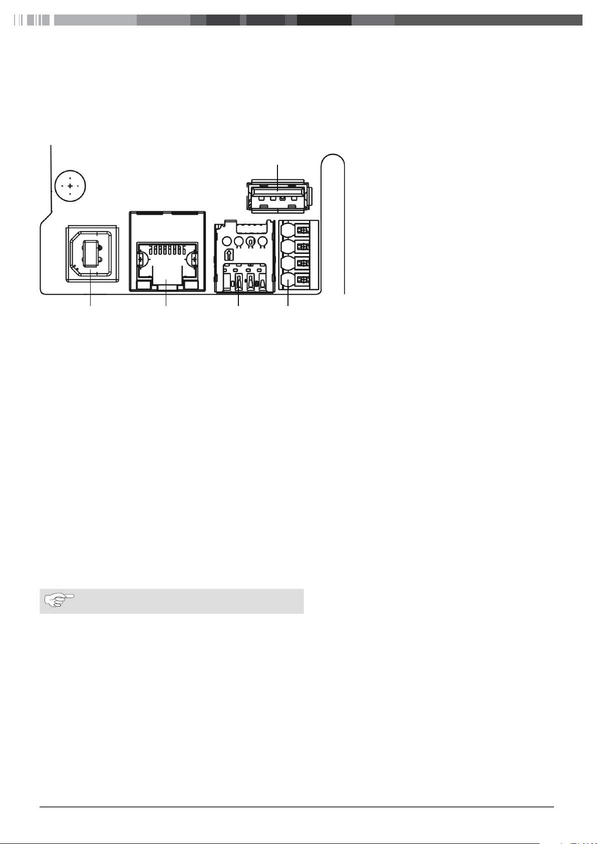
2 Description of data interfaces
2345
2.1 Overview
With the cover open, the data interfaces can be found on the left-hand side in the connection area. This area is separated from the
power supply area by a plastic partition wall.
1
Pin 1
Fig. 01:
Overview of interfaces
2.2 USB type A
This connection is used in host mode for a USB stick for software or configuration updates. This connection supports the 5V power supply up to maximum 100mA.
2.3 RS485 (Modbus) and CP
Overview of push-in terminals from top to bottom:
1. RS485 (GND) – External Modbus
2. RS485 (A, /D) – External Modbus
3. RS485 (B, D) – External Modbus
4. CP line charging cable (control line between vehicle and charging station)
The Modbus data connection to a primary electricity meter can be established for advanced power management. This is done with a
RS485 interface using the top three push-in terminals.
Comply with the following connection parameters at the electricity meter:
■
Insert the RS485 bus cable, sheath dielectric strength 600V, shielded
■
Connection parameter: „10.4 Dynamic Load Management (DLM) (local dynamic load management)“ on page 19
2.4 SIM cardslot for modem
If it is necessary to change a GSM provider, then the SIM card can be removed from the SIM card slot and an alternative SIM card can
be inserted.
NOTE
Not automatically ejected by a spring.
Prerequisites for using a SIM card:
■
Form factor 3FF (micro SIM)
■
A "Machine-to-Machine"-compatible M2M SIM card without PIN enabled by provider
2.5 LAN (RJ-45)
For connecting the charging station to the wired network infrastructure at the installation location. The charging station can be controlled using this connection if there is a connection to the back end or to the local power management system.
2.6 USB type B
Connection for making a USB connection to a computer for configuring the Webasto Live. Connection for making a USB connection to
a computer for configuring the Webasto Live. The USB connection functions as a network interface that allows you to access the web
configuration interface.
5
Page 6

2.7 WLAN (not shown in Fig. 1)
After completing the start process of the charging station, you have the option to connect a WLAN-enabled computer or mobile device
to the charging station hot spot to configure the charging station. The charging station can also be integrated into a home network via
WLAN or a hot spot for a network of charging stations can be created.
6
Page 7
3 Accessing the configuration interface
The configuration interface can be accessed via WLAN, LAN or USB. Webasto recommends Mozilla Firefox for the local configuration.
CAUTION
The configuration interface may only be accessed by a
qualified electrician using a USB or LAN cable.
NOTE
Webasto recommends that configurations be made using the integrated configuration hot spot.
NOTE
The LAN interface can be used only after configuring
the LAN interface in the web interface („7.2 LAN“ on
page 12).
3.1 Configuration via the integrated configuration hot spot
XActivate WLAN on your computer.
XUse the WLAN name (SSID) to search for the configuration hot spot which corresponds to the serial number of your charging station.
NOTE
You can find the serial number of your charging station
on the rating plate on the right side of the charging
station.
XConnect to the charging station configuration hot spot. The hot spot password can be found on the label in the supplied manual.
NOTE
You can deactivate the charging station hot spot via
the configuration interface at any time or set up encryption yourself.
XOpen the browser on your computer and enter the following URL into the address bar: 172.20.0.1
XType the login password of the Webasto Live into the website that now appears. You can find the password on the label in the sup-
plied manual.
3.2 Configuration via USB
XPlug the USB cable (A connector to B connector) into the USB-B port of the charging station communication interface (Fig. 1) and the
A connector to your laptop.
NOTE
The USB cable is not included in the scope of delivery
and must be purchased separately.
XOpen the browser on your laptop and enter the following URL into the address bar: 192.168.123.123
XType the login password of the Webasto Live into the website that now appears. You can find the password on the label in the sup-
plied manual.
3.3 Configuration via LAN
XConnect the charging station and your laptop computer using a suitable LAN cable.
NOTE
The IP address of the charging station connection is
preconfigured when delivered. To be able to access the
charging station with a laptop, you must assign the following IP parameters to the Ethernet port of your laptop:
IP address: 192.168.0.150
Subnet mask: 255.255.255.0
XOpen the browser on your laptop and enter the following URL into the address bar: 192.168.0.100
XEnter the charging station password into the now open login screen. The password can be found on the label in the supplied manual.
NOTE
Webasto recommends that you change the password
using the configuration interface.
7
Page 8
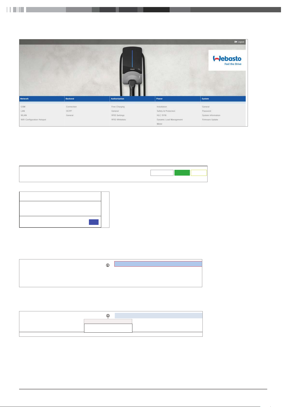
4 General operation of the configuration interface
Fig. 02: Top menu bar
The top menu bar with the menu items of the individual categories can be viewed in the web interface at any time. You can easily jump
back and forth between the menu items.
After changing the parameters in a menu item, they can be saved or discarded with the bottom menu bar. It is also possible to restart
the charging station if this is required to apply the parameters. The bottom menu bar is displayed automatically and the control panels
activated as needed.
Unsaved Changes
Reset all changes
Save
Restart
Fig. 03: Bottom menu bar
Unsaved changes
The page contains unsaved changes.
Please save or reset all changes before leaving this page.
x
Close
Fig. 04: Unsaved changes
When changing to another main category, an automatic check is performed to see if the changes have already been saved. If it has not
been done yet, a warning message appears prompting to save or discard the change. "Reset all changes" is used to reset the parameters to the last saved state, and can take a moment depending on number of parameters being reset.
RCMB Delta
Fig. 05: Value outside of permissible range
1000
Value 1000 not contained in range 0.999
When values outside the permissible range are entered, either a red warning message (at the latest when trying to save) appears at the
bottom left in the screen or a red warning message appears under the input area indicating the permissible value range.
Disconnected Limit [A]
Disconnected Limit [A]
Current limit when disconnected from DLM
network
6
Fig. 06: Advisory text
A short advisory text with configuration tips and detailing the consequences of a change can be found next to every configuration
point. The advisory text can be displayed by hovering with the mouse over the symbol shown.
8
Page 9

Webasto is continuously developing the Webasto Live
charging station software. As a result individual parameters or the look and feel may differ from the configuration shown here. The user interface may contain new
functions that are not listed in these instructions. The
most current version of these instructions can be found
at www.webasto-charging.com.
NOTE
The configuration interface is adapted for being displayed on mobile devices, such as smartphones or tablets. There may be usability restrictions.
NOTE
The configuration interface is currently only available in
English.
9
Page 10

5 Structure of the configuration menu
All the menu items below are shown as they appear in the interface.
Network Backend Authorization Power System
GSM
LAN
WLAN
Connection Free Charging Installation General
OCPP General Safety & Protection Password
General RFID Settings HLC 15118 System Information
Wifi Configuration Hotspot
RFID Whitelist Dynamic Load Management Firmware update
Meter
10
Page 11

6 Initial start-up
Please configure the following parameters before charging with the Webasto Live for the first time as this will ensure that it can be used
properly. To make the initial configuration, connect to the Webasto Live via the configuration hot spot or USB. (see chapter „3 Accessing the configuration interface“ on page 7)
Refer to the description of the individual points when configuring the parameters. Follow the order of the parameters and cross off the
respective parameter in the check list after completing the configuration. The check list can be found under „13.3 Check list for configuring a charging station“ on page 27.
11
Page 12
7 Menu item: Network
7.1 GSM
The Webasto Live supports being connected to the Webasto back end or another OCPP back end. A list of the supported back ends can
be found in the installation instructions or in the data sheet of the Webasto Live. Choose the interface you will use to make a connection. To use the Webasto back end with its Connectivity Services, it is imperative to set the mobile telephone connection using the GSM
menu item and to use the previously factory-fitted SIM card.
The Webasto Live comes as standard with a factory-fitted and inactive SIM card that once activated is used for communicating with the
Webasto Connectivity Services. A different SIM card is required to connect the Webasto Live to a different OCPP back end. The "GSM"
menu item is used to enter the required parameters for this, which you have received from your back end provider.
NOTE
Webasto recommends that the values specified in this
section be adjusted by the installer of the charging station or on request by Support.
Modem Access Technology – Selecting the mobile telephone standard
The Webasto Live mobile modem enables communication via 2G (GPRS, Edge), 3G (HSDPA) and 4G (LTE) for transferring data to a back
end. When delivered, the charging station automatically chooses the best available network quality only if the SIM is activated (this is
done only when the Webasto Connectivity Service is used). It may be necessary in locations where coverage fluctuates strongly to specify the mobile telephone standard. To establish the connection with a particular network operator, enter this in manually under the "Requested Network Operator" parameter and set the "Network Selection Mode" point to "Manual".
7.2 LAN
The Webasto Live has an integrated RJ45 Ethernet port that is used for being integrated into an existing tethered network or to establish a charging station network.
Mode for network configuration – Setting the IP address parameters for the local area network
The Webasto Live LAN network interface can be used as a client for an existing network or as a server to establish a new network.
Select "Auto (DHCP client)" if you would like to integrate the charging station into your home network.
Select "Manual config" to integrate it into an existing network which requires a fixed assignment of parameters. Fill the fields shown
with the network parameters used in the destination network accordingly.
Select the "DHCP server" to set up a network that is managed independently by Webasto Live. The charging station assigns all the nec-
essary parameters to the devices that are also on the network. Note that all other charging stations and devices must be configured in
the network as "Auto (DHCP client)", as there may otherwise be an address conflict.
NOTE
Webasto recommends that communication between
the charging stations be carried out using an external
switch/router and via LAN cables when internal load
management is used. The IP addresses of the individual
charging stations should be configured manually so
that a unique assignment in the network is possible.
7.3 WLAN
The Webasto Live can also be integrated into an existing WLAN. WLAN can also be used to network multiple Webasto Lives with each
other. The Webasto Live automatically selects the encryption process used for your network once the network password has been entered.
NOTE
The Webasto Live WLAN module is not suitable for establishing a separate WLAN network or for strengthening (repeater) an existing network.
WLAN SSID – Name of the existing WLAN network
Enter the name of the network you would like to connect the Webasto Live to here. Pay careful attention to the correct spelling of the
network name and the use of upper and lower case.
WLAN password – Password of the available WLAN network
Enter the password of the network you would like to connect the Webasto Live to here. Pay careful attention to the correct spelling of
the network name and the use of upper and lower case.
Mode for network configuration – Setting the IP address parameters for the WLAN network
The WLAN interface of the Webasto Live can only be used as a client for an existing network.
12
Page 13
Select "Auto (DHCP client)" if you would like to integrate the charging station into your home network. Your wireless router automatically transfers the necessary settings to the Webasto Live.
Select "Manual config" to integrate it into an existing network which requires a fixed assignment of parameters. Fill the fields shown
with the network parameters used in the destination network accordingly.
7.4 Wifi Configuration Hotspot
When delivered, the Webasto Live has an activated and encrypted WLAN hot spot. This hot spot is only suitable for configuring the
Webasto Live and cannot be used to access the internet.
NOTE
Webasto recommends that you adjust the following
parameters of the configuration hot spot as the final
step in the initial start-up.
NOTE
If currently accessing the configuration interface via the
configuration hot spot, the changes to the parameters
once successfully saved must also be saved for the
wireless connection on the configuration PC, as access
to the interface is otherwise not possible.
Hotspot enabled – Deactivating the Webasto Live configuration hot spot
This parameter can be used to deactivate the Webasto Live configuration hot spot. Set the parameter to "Off" to deactivate the hot
spot.
NOTE
If the configuration hot spot has been deactivated, the
configuration interface can only be accessed via the
configured WLAN or LAN connection or the USB cable.
(see "Accessing the configuration interface").
NOTE
Webasto recommends changing the hot spot password
during the initial configuration or deactivating the hot
spot so that unauthorized persons cannot gain access.
Hotspot SSID – WLAN-name (SSID) of the Webasto Live configuration hot spot
An individual network name can be assigned so that the associated Webasto Live configuration hot spot can be identified. When delivered, the serial number of the Webasto Live is registered as the WLAN name to enable a unique assignment of the configuration hot
spot.
Encryption – Encryption process of the Webasto Live configuration hot spot
Select a desired encryption process for the configuration hotspot.
NOTE
Webasto recommends that the configuration hotspot
be encrypted using "WPA2-PSK CCMP"
Hotspot password - Password for the Webasto Live configuration hot spot
Specify the network password for the configuration hot spot of the Webasto Live.
NOTE
Webasto recommends the use of a unique password
with at least eight characters.
Hotspot subnet
This parameter is used to specify the IP address range in which the hot spot is located.
Hotspot netmask
This parameter is used to specify the IP net mask in which the hotspot is located.
DHCP server enabled
This parameter is used to specify if the Webasto Live charging station should function as a DHCP server for the hot spot. This value
should be deactivated if you would like to connect multiple charging stations using this hot spot but would like to assign the IP addresses of the other devices manually.
DHCP server gateway and DHCP server DNS do not currently need to be filled
13
Page 14
8 Menu item: Back end
8.1 Connection
Backend connection type – Connection type to the back end
The Webasto Live supports being connected to the Webasto Connectivity Service or an OCPP back end. Choose the interface you use to
make a connection.
GSM, Ethernet, USB (currently deactivated), WLAN
NOTE
Webasto recommends connecting via the integrated
SIM card using GSM and the OCPP protocol.
The Webasto Live can be connected to the back end of different operators using OCPP (Open Charge Point Protocol). When delivered,
the charging station is preconfigured with the parameters for the Webasto Connectivity Service. Change the parameters to match your
back end operator's presettings so you can connect the Webasto Live to the back end. The supplied SIM card may need to be exchanged to connect with the back end. Contact the operator of the back end about this as well.
NOTE
In order to use the Webasto back end, the predefined
values must not be changed.
OCPP ChargeBoxIdentity (ChargePointID)
This value is used by the back end supplier to identify the charging station.
Default value: WEBASTO_WEBASTO_AC_LIVE_[serial number]
OCPP Mode
Choice of OCPP standard of the Webasto Live to be used for communication with the respective back end.
Default Value: OCPP-J 1.6
WebSockets JSON OCPP URL of the Backend
Default Value: wss://onboarding.csms.allego.eu/communicator/websockets16
WebSockets keep-alive internal
Default Value: 0
8.2 General information
Restart Transaction after power loss – Continuing the charging process after a power failure
After a power failure, the Webasto Live has the possibility of continuing with a charging process using the same authentication parameters and transmitting these to the back end again.
Default Value: On
Backend Connection Timeout – Time that the charging station waits for messages from the back end
This parameter specifies the time in seconds that a Webasto Live waits for messages from the back end before requesting the message
again. This parameter also defines the time a Webasto Live waits for dialling into the mobile phone network and establishing the connection to the back end. In regions with poor mobile phone reception, It is recommendable to increase this parameter. Setting a too
high value results in a long waiting time until the Webasto Live charging station implements commands from the back end. This can
lead to delays in operation of the charging station.
Default Value: 60
SSL Strictness as client – Requirement for secure transmission of data to the back end
The Webasto Live enables secure communication to a back end using SSL in multiple levels. Not every back end supports or needs this
parameter to be changed.
In order to use the Webasto back end, the predefined values must not be changed. Request the parameter relevant for you from your
back end operator.
Default value: Normal SSL Auth
TCP Watchdog Timeout – Time interval for an automatic restart if the back end connection is lost
The Webasto Live can reboot a system automatically if a long period passes without a connection to the back end. The charging station
establishes a new connection to the back end after a reboot. Set the parameter to the value 0 to deactivate this function.
Default Value: 0
Display backend disconnect as error
When this parameter is activated, the user of the charging station is sent a signal through the LED status bar that the connection to the
back end is malfunctioning. The corresponding LED code can be found in the installation and operating instructions.
Default Value: Off
14
Page 15
9 Menu item: Authorization
9.1 Free Charging
The Webasto Live can be configured using "Free Charging" so that charging processes can be started by the user without authentication.
"Free Charging" is deactivated by default (parameter: "Off"). Both of the supplied RFID transponders are entered in the local access list
when delivered and can be used to activate the charging station.
Since it may nevertheless be required for invoicing purposes to transmit charging processes to a back end, different parameters can be
configured (e.g. for invoicing the processes of a company car).
9.2 Free Charging Mode „On“
Free Charging Mode – Behaviour of the charging station and parameters transmitted for charging processes without authentication
Modus 1: „No OCPP“
No OCPP messages are sent to the back end. No authentication is needed to start the charging process. The charging process starts as
soon as the Webasto Live is connected to the vehicle.
NOTE
It is not possible to end an active charging process
from the back end, because all "Remote Stop" messages are declined due to a missing "Transaction ID".
Mode 2: "With OCPP status notif without auth"
No authentication is needed to start the charging process. The charging process starts as soon as the Webasto Live is connected to the
vehicle. Only OCPP status messages are sent to the back end (e.g. charging point occupied). No "Start transaction" or "Stop transaction"
messages are sent to the back end.
NOTE
It is not possible to end an active charging process
from the back end, because all "Remote Stop" messages are declined due to a missing "Transaction ID".
Mode 3: "With OCPP status notif with auth"
Authentication is required via RFID to start the charging process. Only OCPP status messages are sent to the back end (e.g. charging
point occupied). No "Start transaction" or "Stop transaction" messages are sent to the back end.
NOTE
It is not possible to end an active charging process
from the back end, because all "Remote Stop" messages are declined due to a missing "Transaction ID".
Mode 4: "With OCPP Full fixed RFID with auth"
Authentication is required via RFID to start the charging process. OCPP status messages (e.g. charging point occupied) as well as "Start
transaction" and "Stop transaction" are sent to the back end. The transmitted "Transaction ID" can be specified on the operator screen
under the "RFID Tag for Free Charging with OCPP Full, fixed rfid modes" menu item. "Remote Stop" messages are accepted for the correct "Transaction ID". The charging process can only be stopped locally by the same RFID media that started the charging process.
Mode 5: "With OCPP Full fixed RFID without auth"
Authentication is not required via RFID to start the charging process. The charging process starts as soon as the Webasto Live is connected to the vehicle. OCPP status messages (e.g. charging point occupied) as well as "Start transaction" and "Stop transaction" are sent
to the back end. The transmitted "Transaction ID" can be specified on the operator screen under the "RFID Tag for Free Charging with
OCPP Full, fixed rfid modes" menu item. "Remote Stop" messages are accepted for the correct "Transaction ID". The charging process is
ended when the vehicle changes to charging status A or the cable is removed.
Mode 6: "With OCPP Full any RFID"
Authentication is required via RFID to start the charging process. OCPP status messages (e.g. charging point occupied) as well as "Start
transaction" and "Stop transaction" are sent to the back end. The transmitted "Transaction ID" is the ID of the currently used RFID media. "Remote Stop" messages are accepted for the correct "Transaction ID". The charging process can only be stopped locally by the
same RFID media that started the charging process.
9.3 Free Charging Mode „Off“
If in doubt allow charging – In case of doubt allow charging
With this parameter you can configure how the Webasto Live should behave when authentication of the user is not possible due to no
communication or a lost connection to the back end. Authorisation of the user is allowed temporarily until the parameters can be
15
Page 16
checked again. Choose the "Immediately when plugged" parameter to start the charging process immediately after plugging in the vehicle. Choose "On" when the customer would like to use the RFID media first to enable the charging station.
Default Value: Off
NOTE
Webasto recommends the "On" variant because the
data of the RFID media is checked against the back end
when reestablishing the back end connection.
9.4 General information
Vehicle Connection Timeout – Time available for plugging in the vehicle
This parameter is used to configure the period in seconds in which the Webasto Live remains in "Ready" mode until a vehicle is plugged
in, after successful authentication via LiveApp or RFID.
Default Value: 45
Send Authorize for RemoteStart – Behaviour when the charging process is started via an OCPP back end
Set the parameter to "On" when the charging process has been started remotely and the Webasto Live should transmit an authorisation
message to the back end.
Default Value: On
9.5 RFID Settings
RFID Tag letter case – Transmission mode of the RFID tag to the back end
The Webasto Live supports the configuration of how the RFID tag (HEX string) can send messages to the back end during the "Start
Transaction" and "Stop Transaction". In addition to the use of upper and lower-case letters, the order of the bytes can also be defined.
Default Value: Lower Case
NOTE
In order to use the Webasto back end, the predefined
values must not be changed.
9.6 RFID Whitelist
Enable local whitelist – Local administration of RFID media for enabling charging processes on the Webasto Live
To limit access and use of the Webasto Live to a group of users, there is the possibility to store RFID transponder for local activation in
every Webasto Live. Activate the parameter for using the local memory for authorisation on the RFID transponders of the Webasto Live.
NOTE
Please note the supported RFID standards of the
Webasto Live. Not all media are suitable for authentication.
NOTE
The local authorisation lists are not transmitted and not
compared within a group of several Webasto Live. The
lists must be entered manually into each charging station.
NOTE
Webasto recommends the use of the Webasto Connectivity Service or a different OCPP back end for administrating several Webasto Lives. This is the only way to
ensure that the same parameters are applied to all
Webasto Live.
List of entries in local whitelist – locally enabled RFID media for charging at theWebasto Live
RFID media that are entered in this list are enabled independently of a connection to the back end.
To add a new entry to the list, enter the RFID tag of the desired RFID transponder in the text field. Use a colon as a separator between
each RFID media. Example: "AA3E4F16:FE46E313"
To remove an entry from the list, delete the complete list. Afterwards, enter all transponders which should remain in the list again. It is
not possible to delete individual entries.
Enable OCPP whitelist – Back end administration of RFID media for enabling charging processes
This parameter activates the temporary intermediate memory for RFID transponders that have already been authorised by the back end.
This means an authorisation does not need to be requested from the back end when the charging processes are repeated with previously enabled RFID cards. List of entries in OCPP whitelist – RFID media enabled by the back end for charging at theWebasto Live
16
Page 17

To add a new entry to the list (max. 80 entries), enter the RFID tag of the desired RFID media in the text field. Use a colon as a separator
between each RFID media. Example: "AA3E4F16:FE46E313"
To remove an entry from the list, delete the complete list. Afterwards, enter all media which should remain in the list again. It is not
possible to delete individual entries.
NOTE
The supplied RFID media are entered in the OCPP
whitelist. These numbers can be checked if necessary.
Compare the serial number of the key fob (printed on
the back) with the number on the packaging. The following combination of letters and numbers is the relevant number of the RFID media. Example:
00000012:AA3E416B2D35381
17
Page 18

10 Menu item: Power
NOTE
Webasto recommends that the values specified in this
section be adjusted by the installer of the charging station.
10.1 Installation
Operator Current Limit (A) – Maximum current intensity that is signalled to the vehicle
This parameter defines the maximum value in ampere which is signaled to the vehicle for charging. The parameter must not be higher
than what the automatic cutout installed upstream of the charging station will allow or what is allowed to be provided through the
connection cable and charging cable.
CAUTION
A risk of fire exists if the maximum permissible values for
the current intensity of the power supply and the charging cable are exceeded.
NOTE
Observe the valid national standards and regulations
when setting of the maximum charging current.
Phases connected to the Charge Point – Connected power supply phases
Select the connected power supply phases.
Choose "Single-Phase-System" if it is a single-phase power connection including the neutral conductor and the earth.
Choose "Single-Phase-System" (IT-earthing) if it is a single-phase power connection, including the neutral conductor but with no earth.
Choose "Three-Phase-System" if it is a three-phase power connection, including the neutral conductor with or without earth.
Phase rotation of the Charge Point – Specifying the direction of rotation of the power supply phases
Select the order for connecting the power supply as per the power connection.
NOTE
To use "Dynamic Load Management" with phase imbalance detection, the correct connection order of the
individual phases must be stored. The Webasto Live
can otherwise not calculate the available power correctly and will distribute the loads wrongly.
Randomise charging after power loss – Random restart of the charging processes after a power failure
To prevent a renewed failure of the power grid after a power failure due to simultaneously restarting multiple charging processes, the
Webasto Live has the possibility to support peak load distribution when power is restored. Multiple charging stations connected to a
main power supply each start at a different time slightly delayed with a random value of up to 30 seconds.
10.2 Safety & Protection
NOTE
Webasto recommends that the values of the charging
station only be adjusted by the installer or on request
by Support.
Temperature Report Delta – Adjusting the limit value for transmitting the temperature change to an OCPP back end
In the event of errors occurring repeatedly due to excessively high temperatures, the Webasto Live can automatically send a message to
the OCPP back end used. This may be required by Support for remedying the error. Enter in degrees centigrade the desired temperature
change for sending the report automatically. The parameter 0 deactivates automatic sending.
Default Value: 5
RCMB Delta – Adjusting the limit value for transmitting the deviations in the current intensity to an OCPP back end
In the event of errors occurring repeatedly due to fluctuations in the current intensity, the Webasto Live can automatically send a message to an OCPP back end or the Webasto Connectivity Service. This may be required by Support for remedying the error. Enter in
tenths of a milliampere the desired change in the current intensity for automatically sending the report. The parameter 0 deactivates automatic sending.
Default Value: 0
18
Page 19

10.3 HLC 15118 (ISO 15118)
The Webasto Live supports charging in accordance with ISO 15118. These parameters are used to configure the implementation of ISO
15118 communication with the vehicle. The parameters required by your vehicle can be found in your vehicle documents.
NOTE
Only a few manufacturers have currently implemented
ISO 15118 in their vehicles. This is a future standard,
which is already supported today by Webasto in the
Webasto Live.
10.4 Dynamic Load Management (DLM) (local dynamic load management)
The Webasto Live can be operated in the local load management both as a master and a slave. Note that there may only be one DLM
master for each load management cluster.
NOTE
Webasto recommends that the DLM only be adjusted
by the installer of the charging station.
NOTE
The load management of the Webasto Live is based on
calculating the charging current and not on the measured power values. The supply voltage (power source
voltage) as well as the connected phases (phase connected to the charge point) and the rotation direction
(phase rotation of the charge point) must be configured correctly.
The load management supports different hierarchical levels with definable upper limits. These must be stored in the master charging
station. The levels are shown schematically below.
Mode 1: DLM Master (with internal DLM-Slave)
When this parameter is selected, the Webasto Live, which assumes the master role, takes into account its own charge point within the
load management.
Mode 2: DLM Master (Standalone)
When this parameter is selected, the charge point of the master charging station is not taken into account in the load management. The
maximum available power for charging processes can be provided there.
Mode 3: DLM Slave (Master-Auto-Discovery)
Choose this parameter to integrate the Webasto Live as a slave into a charging cluster. The Webasto Live automatically looks for the responsible master by means of the configured DLM network ID.
Mode 4: DLM Slave (Master-Fixed IP)
Choose this parameter to operate the Webasto Live as a slave in a cluster. To detect the correct master its address must be configured
in the network.
DLM master settings:
DLM Network Id – ID of the charging cluster which administrates the Webasto Live
Enter the ID of the charging cluster here that the Webasto Live should administrate as a master. You can enter any number between 1
and 255. Note that each master charging station may be assigned to only one single DLM network.
DLM Algorithm – Algorithm for the load management (no selection currently possible)
Select the algorithm here which should be used for distributing the load in the charging cluster. Webasto is working continuously on improving and choosing the load management algorithms which are then made available as future firmware updates.
FIFO – Uniform distribution of the charging power at all charging stations
The available charging power is divided up equally between all charging stations in a load management cluster. If no available power is
present and a new vehicle would like to start a charging process, it must wait until sufficient charging power is available.
DLM Algorithm Sample Rate – Interval between two iterations of the load management algorithm
This parameter is used to adjust the interval in which the master calculates and distributes new default values for the slaves. If a new vehicle starts a charging process during an interval, then the power available is immediately calculated and returned as a default value to
this vehicle. If an external meter is used, the meter readings between the iterative steps are averaged.
Default Value: 30
19
Page 20

EVSE- Sub-Distribution Limit (L1/L2/L3) (A) – Maximum available current intensity for the complete load management cluster
This parameter is used to configure the maximum current intensity for each phase which is provided to the entire charging cluster. This
represents the absolute upper limit of the load management and must not exceed the values available in the installation for the common connection point.
NOTE
If multiple charging clusters are used at a common connection point, the total value of all charging clusters
must not exceed the available current intensity.
Default Value: 16, 16, 16
Operator EVSE- Sub-Distribution Limit (L1/L2/L3) (A) – Maximum current intensity to be distributed for the complete load
management cluster
The parameter configured here must not exceed the values of the "EVSE Sub-Distribution Limit", and should be below the "EVSE
Sub-Distribution Limit" parameter. This parameter can also be used to adjust the value actually assigned to the charging cluster during
operation.
One OCPP back end can adjust this value dynamically and the local load management can be integrated into a back end-based load
management. The back end cannot set any parameters that exceed the "EVSE Sub-Distribution Limit" parameter.
Default Value: 16, 16, 16
External Meter Support – Using an external electricity meter to support the load management
The Webasto Live supports the integration of an external default value for the local load management. To do this, connect the external
meter to the master charging station for the load management using the external Modbus connection and configure the external measuring device with the following parameters. Ensure correct polarity of the connection:
Parameter Value
device ID 2
Baudrate 9600
parity Even
stop bit 1
word length 8
Polarity D and /D
Termination Yes
Contact the manufacturer of the electricity meter for details on configuring the parameters of the external measuring device.
Default Value: Off
NOTE
Use three-phase measuring devices only.
Meter configuration (Second)
This parameter is used to configure the model of the external meter. The Webasto Live supports different types of external meters. If
your available meter type is not listed, then please consult the manufacturer of the electricity meter. Webasto is constantly checking the
functionality of other electricity meters so that electricity meters that are not on the list can also be used.
Main Distribution Limit (L1/L2/L3) (A) – Maximum available current intensity on the external meter
This parameter is used to configure the maximum upper limit of the current intensity that must not be exceeded at the external meter.
By measuring the real draw, the remaining available current intensity is distributed in the charging cluster taking into account the operator EVSE-Sub Distribution Limit as well as the EVSE-Sub Distribution Limit.
Default Value: 100, 100, 100
External Meter Disconnected Fallback (L1/L2/L3) (A) – Limit in case of a connection failure of the external meter
In case of a connection failure between the master and external meter, this parameter can be used to define a maximum upper limit
that is available for distribution from the master charging station to the slave charging stations.
Default Value: 9999, 9999, 9999
External Meter Location – Reading from the external meter incl./excl. the charging cluster
This parameter can be used to define whether the reading delivered by the external meter already contains the volume of purchased
electricity from the charging cluster or whether this must still be added in order to not exceed the main distribution limit.
Default Value: Including EVSE Sub distribution
20
Page 21

External Meter Sample Rate – Interval in which the readings from the external meter of the master charging station are
made available (no selection currently possible)
This parameter is used to configure the time interval in which the external meter of the master charging station provides readings. If
necessary, adjust the interval to the specifications of your back end provider.
NOTE
Refer to the specifications of the external measuring
device.
Current Imbalance Prevention – Taking into account the phase imbalance for the load management
The load management of the Webasto Live can incorporate a limitation of the maximum phase imbalance at the connection point. Set
the parameter to "On" to activate the function.
Default Value: Off
Current Imbalance Limit – Maximum phase imbalance for the load management
Here you can configure the maximum current value for the load management that should be incorporated as the delta between the individual phases. The master charging station distributes the available volume of purchased electricity according to the connected vehicles.
NOTE
The supply voltage (power source voltage) as well as
the connected phases (phase connected to the charge
point) and the rotation direction (phase rotation of the
charge point) must be configured correctly in order to
enable a distribution with phase accuracy.
Default Value: 20
Minimum Current Limit (A) – Minimum available charging current
This parameter is used to configure the lower limit of the load management. This parameter is used to provide a minimum charging current for charging processes at the internal slave of the master charging station.
NOTE
Pause the charging process for vehicles with charging
currents < 6A.
Default Value: 6
Disconnected Limit (A) – Limit in case of a connection failure between the master and internal slave
In case of a connection failure between the master and internal slave, this parameter can be used to define a maximum upper limit that
the slave should use if necessary.
NOTE
Pause the charging process for vehicles with charging
currents < 6A.
Default Value: 6
DLM slave settings:
DLM Network id – ID of the charging cluster with which the slave charging station should be connected
Enter the ID of the charging cluster that the Webasto Live should connect to here. The Webasto Live then establishes a connection to
the corresponding master charging station. All currently connected slave charging stations as well as their assigned volume ofpurchasedelectricity can be monitored in the dashboard of the master charging station.
DLM Master IP and port – IP address and port of the master charging station
If you have not connected the charging station to a master using the DLM ID, you can enter the IP address as well as the associated
port of the master charging station in here.
Example: 192.168.0.100:80
Minimum Current Limit (A) – Minimum available charging current
This parameter is used to configure the lower limit of the load management. This parameter is used to provide a minimum charging current to the master charging station which is then used for charging processes at the internal slave.
NOTE
Pause the charging process for vehicles with charging
currents < 6A.
Disconnected Limit (A) – Limit in case of a connection failure between the master and external slave
In case of a connection failure between the master and external slave, this parameter can be used to define a maximum upper limit that
the slave should use if necessary.
21
Page 22

NOTE
Pause the charging process for vehicles with charging
currents < 6A.
10.5 Meter (Electricity meter)
NOTE
Webasto recommends that the value of the charging
station only be adjusted by the installer. Changing the
interval can influence the quality of the back end load
management as well as how the charging processes
are displayed.
Meter Value Sample Interval (OCPP) – Adjusting the interval for transmitting the meter reading to an OCPP back end during a charging process
The current meter reading of the internal meter is transferred when the Webasto Live is used with an OCPP back end. This parameter
can be used to configure the second interval between two transmitted meter readings during an active charging process. Choose a value between 60 and 3,600 or 0 to deactivate transmission during the charging process. If the parameter "0" is selected, the meter reading continues to be transmitted at the start and the end of the charging process.
Default Value: 300
Clock aligned data interval (OCPP) – Adjusting the interval for transmitting the meter reading to an OCPP back end without
an active charging process
The current meter reading of the internal meter is transferred when the Webasto Live is used with an OCPP back end. This parameter
can be used to configure the second interval between two transmitted meter readings during an active charging process. Choose a value between 60 and 3,600 or 0 to deactivate transmission of the meter reading without an active charging process. If the parameter "0"
is selected, the meter reading continues to be transmitted at the start and the end of the charging process.
Default Value: 0
22
Page 23

11 Menu item: System
11.1 General information
UTC time for housekeeping reboot – Time required for automatic restart of the charging station
The Webasto Live has an automatic restart function for when the charging station has not restarted within the last 30 days. This parameter can be used to configure the time for the automatic restart according to UTC Standard Time. The restart is only executed after 30
days if no vehicle has been connected to the charging station. Enter the desired time in the range of 0-23 (full hours) into the text field.
Default Value: 1
Factory Reset by RFID – Resetting to factory settings using RFID media
The Webasto Live has the function for resetting all configurations made back to the factory settings. This is done, for example, using the
number of the RFID media that is supplied and stored here and is held to the RFID reader for at least 120 seconds. An acoustic signal
sounds after this time has elapsed. The numbers of the two RFID media supplied with the charging station are stored by default. Alternatively, other RFID media can also be entered as described below.
NOTE
Up to two numbers of RFID media for a reset to factory
settings can be stored.
NOTE
Webasto recommends the use of the two supplied
RFID media.
1. Enter the number of the RFID media in the text field that you would like to use for the reset to factory settings.
NOTE
Enter the number of the RFID media in digits and in
lower-case letters.
2. Click on "Save" in the bottom menu bar.
Log Level – Specifying the desired logging level for error cases
The Webasto Live has automated logging of error cases. This can help the remote support team when rectifying a fault when it occurs.
This menu can be used to select the scope of error logging.
Default Value: LOG_LEVEL_DBG
LED Brightness – Adjusting the brightness of the integrated LED status bar
The brightness of the LED status bar can be adjusted in 1% steps using this menu item.
Default Value: 100
NOTE
Complete deactivation of the LED status bar is not possible because it fulfills a security relevant function. Error
messages present in the charging station are still displayed with 100% brightness even after changing the
parameter and displayed with the corresponding light
scheme in order to inform the user about anerror.
Enable Sound – Switching the audio output of the charging station on and off
The "Enable Sound" menu item is used to switch the integrated sound module of the charging station on and off. Warnings are always
signaled.
Default Value: On
11.2 Password – Login password for the web interface
Change the login password for accessing the web interface and save it by clicking on "Save" in the bottom menu bar.
NOTE
The login password for the charging station can be
changed only after defining the RFID media for factory
settings.
NOTE
After the reset to factory settings („11.1 General information“ on page 23), reset the login password again
to the password specified in the supplied manual.
23
Page 24

11.3 System Information
The "System information" provides you with information about the software versions of the individual system components. You may be
required to provide Support with this information for a better diagnosis if there is an error.
11.4 Firmware update
To update the firmware of the charging station to the latest version, please proceed as follows:
NOTE
Before installing the update, make sure that there is no
charging process running and the charging station is in
stand-by mode.
1. Download the current firmware version onto your PC under https://webasto-charging.com/default/documentation/.
2. Click on the "Select file (.deb)" button in the configuration interface
3. Navigate to the storage location of the downloaded firmware and select it.
4. Make sure that you have selected the correct firmware version.
5. Click on the "Upload & Install" button.
6. The firmware update is executed. You receive continuous information about the progress of the update as messages on the interface.
NOTE
Do not interrupt the power supply to the charging station during the update under any circumstances. The
charging station restarts several times during the update process.
7. After the update has been successfully installed, the "Firmware update successful" message appears on the web interface. You can
now use the charging station again.
NOTE
Webasto makes new software versions available on the
Webasto website at regular intervals. Webasto Connectivity Service customers automatically have the latest
version of the software transferred to their charging
station.
24
Page 25

12 Connectivity (if part of the product)
To be able to use connectivity, it is a prerequisite that
you purchase Webasto Live with the desired package in
the Webasto Online Shop at www.webasto-charging.
com.
Connectivity is used for analysis, monitoring, billing and comfort functions. Please find out more about possible functions at
www.webasto-charging.com.
12.1 Purchasing and setting up the Webasto Charging App + Portal
The Webasto Charging App can be found in iTunes and the Google Play Store. Enterthe search string 'LiveApp' to download it.
12.2 Access to the Webasto EV Driver Portal
In the Home package you receive an access link for web-based 'Live Portal Plus' via email after purchasing Webasto Live with connectivity services
If you have registered for the Professional package, you receive an access link for web-based 'Live Portal Plus'.
12.3 Overview of Live Portal and Live Portal Plus
You receive information about the charging processes for the Live Portal and Live Portal Plus. The app allows you to use mobile and location-independent functions for charging the electric vehicle.
An overview of the functions and app are described on the website www.webasto-charging.com.
12.4 Installation instructions for connectivity
The connectivity of your Webasto Live is established automatically using the integrated eSIM card if you have registered with this service. The delivery with the default configuration provides a GSM connection, a connection via WLAN is possible, but requires an additional configuration (further information can be found in chapter 6). Consult a technician or our installation service for installation.
Updating the app and the EV Driver Portal
When new software versions become available, you are are automatically informed of an update via the app. The most current version
is always displayed on the screen when you log-in to the EV Driver Portal.
12.5 Adding additional RFID media
You can add additional 'Live Access' RFID media in the app and in the Live Portal. Additional RFID media are added in the Live Portal on
the start page by clicking on "+". The RFID media can be added in the personal settings of the app. The RFID media number can be
found on the label of the RFID media and on the packaging.
25
Page 26

13 Annex
13.1 Glossary
Term Description Reference in chapter
Backend Web interface which is provided on a computer at a provider 8 on page 14
Client mode Charging station appears as a network participant and receives a network address 2.2 on page 5
CP line "control pilot", control line in the charging cable 2.3 on page 5
Encryption Algorithm for encrypting data 7.4 on page 13
Firmware Application in the charging station that controls all the processes during operation 11.4 on page 24
Host-Modus Charging station appears as a server in the network and assigns network addresses 2.2 on page 5
Hotspot Functionality of the charging station for accessing the configuration interface via WLAN 7.4 on page 13
IP address Network address of a network device 7.2 on page 12
Meter Electricity meter 5 on page 10
Modbus Communication protocol on the data line between electricity counter and charge controller 2.3 on page 5
Netmask Integral part of a name of a network configuration 7.4 on page 13
Provider Provider of a service 2.4 on page 5
RFID-tag /
RFID-medium
Router Network device that can establish data links 7.3 on page 12
Subnet Integral part of a name of a network configuration 7.4 on page 13
Transaction ID Unique identifier for a charging process 9.2 on page 15
Webinterface Configuration interface of the charging station, accessible via data interfaces 4 on page 8
Whitelist List of approved media for authentication 9.6 on page 16
Unique identifier of a medium which is used for authentication 9.5 on page 16
13.2 List of abbreviations
Term Meaning Description Reference in chapter
DHCP "Dynamic Host Configuration Protocol" Regulates address assignment in the network 7.2 on page 12
DLM "Dynamic Load Management" Algorithm for distributing peak loads in multiple
charging stations
DNS "Domain Name Service" Network service for resolving network names 7.4 on page 13
EDGE "Enhanced Data Rates for GSM" Development stage in the mobile phone technology
for data transmission
EVSE "Electric vehicle supply equipment” Charging station 10.4 on page 19
FIFO "first in, first out" Algorithm for uniform distribution of charging ser-
vices
GPRS "General Packet Radio Service" Mobile phone technology for data transmission 7.1 on page 12
GSM "Global System for Mobile communications" General name for mobile communications 7.1 on page 12
HLC
15118
HSDPA "High Speed Downlink Packet Access" Development stage in the mobile phone technology
JSON "JavaScript Object Notation" Data format for exchanging data 8 on page 14
LAN "Local area network" Wired network 7.2 on page 12
LED "Light Emmiting Diode” 8.2 on page 14
log Event recorder 11.1 on page 23
LTE "Long Term Evolution" Development stage in the mobile phone technology
OCPP “Open Charge Point Protocol” Residual current monitoring device 8 on page 14
RCMB "Residual Current Monitor" Wireless identification 10.2 on page 18
RFID "Radio frequency identification device" Authentication device 5 on page 10
RS485 Data line with a special data transmission protocol 2.3 on page 5
SIM "Subscriber identity module" Chip card for mobile communications 7.1 on page 12
SSID "Service Set Identifier" Name of a WAN hot spot 7.3 on page 12
"PLC-based High Level Communication" Data communication on the CP line 10.3 on page 19
for data transmission
for data transmission
10.4 on page 19
7.1 on page 12
10.4 on page 19
7.1 on page 12
7.1 on page 12
26
Page 27

Term Meaning Description Reference in chapter
SSL "Secure Sockets Layer" Encryption protocol 8.2 on page 14
TCP "Transmission Control Protocol" Data transmission protocol in the Internet 8.2 on page 14
URL "Uniform Resource Locator" Notation form of a network address 8 on page 14
USB "Universal serial bus" Data interface 2.6 on page 5
UTC "Universal time coordinated" Global time standard 11.1 on page 23
WiFi Alternative identifier created for WLAN 5 on page 10
WLAN "Wireless local area network" Wireless network 2.7 on page 6
13.3 Check list for configuring a charging station Webasto Live
1. Power:
Installation – Operator Current Limit (9.1.)
Installation – Power source voltage (9.1)
Installation – Phases connected to the Charge Point (9.1)
Installation – Phase rotation of the Charge Point (9.1
2. Authorization:
Free Charging – Free Charging (8.1)
RFID Whitelists – Enable OCPP Whitelists (8.4)
RFID Whitelists – List of Entries in OCPP Whitelists (8.4)
3. System:
Password – Factory Reset by RFID (10.1)
Password – Charging station Password (10.2)
4. Network:
LAN / WLAN (6.3 / 6.4)
Configuration Hotspot – Hotspot enabled (6.5)
Configuration Hotspot – Encryption (6.5)
Configuration Hotspot – Hotspot password (6.5)
The initial installation process is now complete. Your Webasto Live can be used for charging electric vehicles. Additional functions for
operating the charging station are described in these configuration instructions.
27
Page 28

1 Zu diesem Dokument
1.1 Zweck des Dokuments
Diese Konfigurationsanleitung ist Bestandteil des Produkts und enthält alle Informationen zur korrekten und sicheren Konfiguration.
1.2 Umgang mit diesem Dokument
Vor Installation des Geräts die Konfigurationsanleitung durchlesen.
1.3 Verwendung von Symbolen und Hervorhebungen
GEFAHR
Das Signalwort bezeichnet eine Gefährdung mit einem
hohen Risikograd, die, wenn sie nicht vermieden wird,
den Tod oder eine schwere Verletzung zur Folge hat.
WARNUNG
Das Signalwort bezeichnet eine Gefährdung mit einem
mittleren Risikograd, die, wenn sie nicht vermieden
wird, eine geringfügige oder mäßige Verletzung zur
Folge haben kann.
VORSICHT
Das Signalwort bezeichnet eine Gefährdung mit einem
niedrigen Risikograd, die, wenn sie nicht vermieden
wird, eine geringfügige oder mäßige Verletzung zur
Folge haben kann.
HINWEIS
Das Signalwort bezeichnet eine technische Besonderheit oder (bei Nichtbeachtung) einen möglichen Schaden am Produkt.
Verweis auf separate Dokumente, die beigelegt sind
oder bei Webasto angefragt werden können.
1.4 Gewährleistung und Haftung
Webasto übernimmt keine Haftung für Mängel und Schäden, die darauf zurückzuführen sind, dass Einbau- und Bedienungsanweisungen nicht beachtet wurden.
Dieser Haftungsausschluss gilt insbesondere für:
■
Einbau durch ungeschultes Personal
■
Unsachgemäße Verwendung
■
Nicht von einer Webasto Service-Werkstatt ausgeführte Reparaturen
■
Verwendung von Nicht-Originalersatzteilen
■
Umbau des Geräts ohne Zustimmung von Webasto
■
Beschädigungen am Gerät durch mechanische Einflüsse
■
Bei Nichtbeachtung Inspektions- und Wartungsanweisungen
28
Page 29

2 Beschreibung der Datenschnittstellen
2345
2.1 Übersicht
Bei geöffneten Deckel befinden sich auf der linken Seite im Anschlussbereich die Datenschnittstellen. Dieser Bereich ist durch eine Kunststofftrennwand vom Energieanschlussbereich abgetrennt.
1
Pin 1
Abb. 01:
Übersicht der Schnittstellen
2.2 USB Typ A
Anschluss im Host-Modus für USB-Stick für Software- oder Konfigurations-Update. Dieser Anschluss unterstützt die 5V-Energieversorgung bis maximal 100mA.
2.3 RS485 (Modbus) und CP
Übersicht push-in Klemmen von oben nach unten:
8. RS485 (GND) – Externer Modbus
9. RS485 (A, /D) – Externer Modbus
10. RS485 (B, D) – Externer Modbus
11. CP-Leitung Ladekabel (Steuerleitung zwischen Fahrzeug und Ladestation)
Für das erweiterte Power Management kann eine Modbus-Datenverbindung zu einem übergeordneten Energiezähler hergestellt werden. Dies geschieht über eine RS485-Schnittestelle mit den oberen drei push-in Klemmen.
Folgende Anschlussparameter am Energiezähler einhalten:
■
RS485-Buskabel, Mantel-Isolationsfestigkeit 600V, geschirmt
■
Anschlussparameter: „10.4 Dynamic Load Management (DLM) (lokales dynamisches Lastmanagement)“ auf Seite 46
2.4 SIM- Karteneinschub für Modem
Wenn ein Wechsel des GSM-Providers erforderlich ist, dann kann am SIM-card-slot die SIM-Karte entnommen werden und eine alternative SIM-Karte eingesetzt werden.
HINWEIS
Es erfolgt kein automatischer Auswurf durch eine Feder.
Voraussetzungen für das Einsetzen einer SIM-Karte:
■
Formfaktor 3FF (micro SIM)
■
Empfohlen wird eine „Machine-to-Machine“-fähige M2M-SIM-Karte ohne PIN, vom Provider freigeschaltet
2.5 LAN (RJ-45)
Anschluss der Ladestation an eine kabelgebundene Netzwerk-Infrastruktur am Aufstellort. Über diesen Anschluss lässt sich die Ladestation steuern, falls eine Verbindung zu einem Backend oder lokalen Power Management System besteht.
2.6 USB Typ B
Anschluss für die USB-Verbindung zu einem Computer zur Konfiguration der Webasto Live. Anschluss für die USB-Verbindung zu einem
Computer zur Konfiguration der Webasto Live. Der USB-Anschluss hat die Funktion einer Netzwerkschnittstelle, über welche die WebKonfigurationsoberfläche erreicht werden kann.
29
Page 30

2.7 WLAN (Nicht in Abb. 1 dargestellt)
Nach dem vollständigen Startvorgang der Ladestation steht die Möglichkeit zur Verfügung, ein WLAN-fähigen Computer oder mobiles
Gerät mit dem Hotspot der Ladestation zu verbinden um die Konfiguration der Ladestation vorzunehmen. Auch kann die Ladestation via
WLAN in ein Heimnetzwerk eingebunden werden oder einen Hotspot für ein Netz aus Ladestationen erstellen.
30
Page 31

3 Zugriff auf die Konfigurationsoberfläche
Der Zugriff auf die Konfigurationsoberfläche kann über WLAN, LAN oder USB erfolgen. Webasto empfiehlt Mozilla Firefox für die lokale
Konfiguration.
VORSICHT
Der Zugriff auf die Konfigurationsoberfläche über USB
oder LAN-Kabel darf nur durch eine qualifizierte Elektrofachkraft erfolgen.
HINWEIS
Webasto empfiehlt die Konfiguration über den integrierten Konfigurations-Hotspot.
HINWEIS
Die LAN Schnittstelle kann erst nach der Konfiguration
der LAN-Schnittstelle in der Weboberfläche genutzt
werden („7.2 LAN“ auf Seite 37).
3.1 Konfiguration über den integrierten Konfigurations-Hotspot
XAktivieren Sie WLAN auf Ihrem Computer.
XSuchen Sie nach dem Konfigurations-Hotspot mit dem WLAN-Namen (SSID), welcher der Seriennummer Ihrer Ladestation entspricht.
HINWEIS
Die Seriennummer Ihrer Ladestation können Sie dem
Typenschild auf der rechten Seite der Ladestation entnehmen.
XVerbinden sie sich mit dem Konfigurationshotspot der Ladestation – das Hotspot-Passwort entnehmen Sie dem Aufkleber im mitgelie-
ferten Handbuch.
HINWEIS
Sie können den Hotspot der Ladestation über die Konfigurationsoberfläche jederzeit deaktivieren oder selbst
eine Verschlüsselung einrichten.
XÖffnen Sie den Browser Ihres Computers und tippen Sie folgende URL in die Adressleiste ein: 172.20.0.1
XTippen Sie auf der nun geöffneten Website das Login-Passwort der Webasto Live ein, welches Sie dem Aufkleber im mitgelieferten
Handbuch entnehmen können.
3.2 Konfiguration über USB
XStecken Sie das USB Kabel (A-Stecker auf B-Stecker) in die USB-B Buchse des Kommunikationsinterfaces (Abb. 1) der Ladestation und
mit dem A-Stecker an Ihren Laptop.
HINWEIS
Das USB-Kabel ist nicht Teil des Lieferumfangs und
muss separat erworben werden.
XÖffnen Sie den Browser Ihres Laptops und tippen Sie folgende URL in die Adressleiste ein: 192.168.123.123
XTippen Sie auf der nun geöffneten Website das Login-Passwort der Webasto Live ein, welches Sie dem Aufkleber im mitgelieferten
Handbuch entnehmen können.
3.3 Konfiguration über LAN
XVerbinden Sie die Ladestation mittels eines geeigneten LAN Kabels und Ihrem Laptop.
HINWEIS
Die IP Adresse des Anschlusses der Ladestation ist im
Auslieferungszustand vorkonfiguriert. Um mit einem
Laptop auf die Ladestation zugreifen zu können, müssen Sie dem Netzwerkanschluss ihres Laptops folgende
IP Parameter zuweisen:
IP-Adresse: 192.168.0.150
Subnetmaske: 255.255.255.0
XÖffnen Sie den Browser Ihres Laptops und tippen Sie folgende URL in die Adressleiste ein: 192.168.0.100
XTippen Sie im nun geöffneten Login Screen das Ladestation Passwort ein. Das Passwort entnehmen Sie dem Aufkleber im mitgeliefer-
31
Page 32

ten Handbuch.
HINWEIS
Webasto empfiehlt die anschließende Änderung des
Passworts über die Konfigurationsoberfläche.
32
Page 33

4 Allgemeine Bedienung der Konfigurationsoberfläche
Abb. 02: Obere Menüleiste
Die obere Menüleiste mit den Menüpunkten der einzelnen Kategorien sind jederzeit im Webinterface sichtbar. Es ist möglich zwischen
den Menüpunkten beliebig hin und her zu springen.
Nach Änderung der Parameter in einem Menüpunktkönnen diese über die untere Menüleiste gespeichert oder verworfen werden. Ebenso ist es möglich die Ladestation neu zu starten, sollte dies für die Anwendung der Parameter erforderlich sein. Die untere Menüleiste
wird automatisch eingeblendet und die Bedienfelder je nach Bedarf aktiviert.
Unsaved Changes
Reset all changes
Save
Restart
Abb. 03: Untere Menüleiste
Unsaved changes
The page contains unsaved changes.
Please save or reset all changes before leaving this page.
x
Close
Abb. 04: Nicht gespeicherte Änderungen
Bei Wechsel in einen anderen Menüpunkt wird automatisch geprüft, ob die vorgenommenen Änderungen bereits gespeichert wurden.
Falls dies noch nicht geschehen ist, erscheint eine Hinweismeldung, die zur Speicherung oder Verwerfen der Änderung auffordert. Mittels „Reset all changes“ können die Parameter wieder auf den letzten gespeicherten Stand zurückgesetzt werden, dies kann je nach Anzahl der Parameter einen Moment dauern.
RCMB Delta
Abb. 05: Werte außerhalb des zulässigen Bereichs
1000
Value 1000 not contained in range 0.999
Bei Eingabe von Werten außerhalb des zulässigen Bereichs erscheint entweder eine rote Hinweismeldung (spätestens beim Speicherversuch) links unten im Bildschirm oder eine rote Hinweismeldung unter dem Eingabefeld, die das zulässige Wertintervall angibt.
Disconnected Limit [A]
Disconnected Limit [A]
Current limit when disconnected from DLM
network
6
Abb. 06: Hinweistext
Neben jedem Konfigurationspunkt finden Sie einen kurzen Hinweistext, wie dieser zu konfigurieren ist und welche Auswirkungen eine
Änderung hat. Der Hinweistext lässt sich via Mausbewegung über das oben dargestellte Symboleeinblenden.
33
Page 34

Webasto entwickelt die Software der Ladestation
Webasto Live kontinuierlich weiter. Dadurch können
einzelne Parameter oder das Erscheinungsbild von der
hier dargestellten Konfiguration abweichen. Gegebenenfalls sind neue Funktionen in der Bedienoberfläche
enthalten, die in dieser Anleitung nicht aufgeführt sind.
Die aktuellste Version dieser Anleitung finden Sie im unter www.webasto-charging.com.
HINWEIS
Die Konfigurationsoberfläche wird für die Darstellung
auf mobilen Geräten wie Smartphones oder Tablets angepasst. Gegebenenfalls kann es zu Einschränkungen in
der Benutzbarkeit kommen.
HINWEIS
Die Konfigurationsoberfläche ist zur Zeit nur in Englisch
verfügbar.
34
Page 35

5 Aufbau des Konfigurationsmenüs
Nachfolgend sind alle Menüpunkte wie in der Oberfläche dargestellt.
Network Backend Authorization Power System
GSM
LAN
WLAN
Connection Free Charging Installation General
OCPP General Safety & Protection Password
General RFID Settings HLC 15118 System Information
Wifi Configuration Hotspot
RFID Whitelist Dynamic Load Management Firmware Update
Meter
35
Page 36

6 Erstinbetriebnahme
Konfigurieren Sie nachfolgende Parameter vor dem ersten Ladevorgang der Webasto Live, damit diese ordnungsgemäß genutzt werden
kann Um die Erstkonfiguration durchzuführen verbinden sie sich via Konfigurations-Hotspot oder USB mit der Webasto Live. (siehe Kapitel „3 Zugriff auf die Konfigurationsoberfläche“ auf Seite 31)
Die Einrichtung der Parameter können Sie der Beschreibung der einzelnen Punkte entnehmen. Befolgen Sie die Reihenfolge der Parameter und haken Sie nach erfolgter Konfiguration den jeweiligen Parameter in der Checkliste ab. Die Checkliste finden Sie unter „13.3
Checkliste Konfiguration Ladestation“ auf Seite 54.
36
Page 37

7 Menüpunkt: Network
7.1 GSM
Die Webasto Live unterstützt die Verbindung zum Webasto Backend oder einem anderen OCPP-Backend. Eine Liste der unterstützten
Backends finden Sie in Installationsanleitung oder im Datenblatt der Webasto Live. Wählen Sie hier die Schnittstelle, über die eine Anbindung erfolgen soll. Für das Webasto Backend mit seinen Connectivity Services ist es zwingend erforderlich, die Mobilfunkanbindung
über den Menüpunkt GSM einzustellen und die bereits werksseitig verbaute SIM-Karte zu verwenden.
Die Webasto Live wird serienmäßig mit einer werkseitig verbauten und inaktiven SIM-Karte ausgeliefert, welche nach Aktivierung für die
Kommunikation des Webasto Connectivity Services genutzt wird. Zur Anbindung der Webasto Live an ein anderes OCPPBackend ist es
erforderlich, eine andere SIM-Karte zu verwenden. Unter dem Menüpunkt „GSM“ können die dafür notwendigen Parameter eingetragen werden, welche Sie von Ihrem Backend Anbieter erhalten.
HINWEIS
Webasto empfiehlt, Anpassung der in diesem Abschnitt
genannten Werte durch den Installateur der Ladestation oder nach Aufforderung durch den Support vornehmen zu lassen.
Modem Access Technology – Auswahl des Mobilfunkstandards
Das Mobilfunkmodem der Webasto Live ermöglicht die Kommunikation via 2G (GPRS, Edge), 3G (HSDPA) und 4G (LTE) um Daten an ein
Backend zu übertragen. Im Auslieferungszustand wählt die Ladestation automatisch die verfügbare beste Netzqualität im Fall, dass die
SIM aktiviert ist (dies erfolgt nur bei Nutzung des Webasto Connectivity Service). An Standorten mit stark schwankender Netzabdeckung
kann es erforderlich sein, den Mobilfunkstandard festzulegen. Um die Verbindung mit einem bestimmten Netzbetreiber aufzubauen, tragen Sie diesen unter dem Parameter „Requested Network Operator“ manuell ein und setzen sie den Punkt „Network selection mode“
auf „Manual“.
7.2 LAN
Die Webasto Live verfügt über einen integrierten RJ45 Ethernet Port, der für die Integration in ein bestehendes, kabelgebundenes Netzwerk oder den Aufbau eines Ladestation Netzwerks genutzt werden kann.
Mode for network configuration – Einstellen der IP-Adress Parameter für das LAN-Netzwerk
Die LAN-Netzwerkschnittstelle der Webasto Live kann als Client für ein bestehendes Netzwerk oder als Server zum Aufbau eines neuen
Netzwerks benutzt werden.
Wählen Sie „Auto (DHCP client)“ wenn sie die Ladestation in ihr Heimnetzwerk integrieren möchten.
Zur Integration in ein bestehendes Netzwerk, welches eine feste Zuordnung der Parameter erfordert, wählen Sie „Manual config“. Befül-
len Sie die erscheinenden Felder entsprechend den im Zielnetzwerk verwendeten Netzwerkparametern.
Um ein Netzwerk einzurichten, welches von der Webasto Live selbstständig verwaltet wird, wählen Sie „DHCP server“. Die Ladestation
vergibt darauf hin alle notwendigen Parameter an die ebenfalls im Netz befindlichen Geräte. Beachten Sie, dass alle weiten Ladestationen und Geräte im Netzwerk als „Auto (DHCP client)“ konfiguriert werden müssen, da es sonst zu einem Adresskonflikt kommen kann.
HINWEIS
Webasto empfiehlt bei Verwendung des internen Lastmanagements die Kommunikation unter den Ladestationen über einen externen Switch / Router und über
LAN-Kabel vorzunehmen. Die IP-Adressen der einzelnen
Ladestationen sollten manuell konfiguriert werden, um
eine eindeutige Zuordnung im Netzwerk zu ermöglichen.
7.3 WLAN
Die Webasto Live kann in ein bestehendes WLAN integriert werden. Es ist ebenfalls möglich mehrere Webasto Live über WLAN untereinander zu vernetzen. Die Webasto Live wählt nach Eingabe des Netzwerkpassworts automatisch das für Ihr Netzwerk verwendete Verschlüsselungsverfahren aus.
HINWEIS
Das WLAN Modul der Webasto Live ist nicht für den
Aufbau eines eigenen WLAN-Netzwerkes oder zur Verstärkung (Repeater) eines vorhandenen Netzwerkes geeignet.
WLAN SSID – Name des vorhandenen WLAN Netzwerks
Tragen Sie hier den Namen des Netzwerkes ein, mit dem Sie die Webasto Live verbinden möchten. Achten Sie auf die korrekte Schreibweise des Netzwerknamens inklusive der Groß-/Kleinschreibung.
37
Page 38

WLAN Password – Passwort des vorhandenen WLAN Netzwerks
Tragen Sie hier das Passwort des Netzwerkes ein, mit dem Sie die Webasto Live verbinden möchten. Achten Sie auf die korrekte Schreibweise des Netzwerknamens inklusive der Groß-/Kleinschreibung.
Mode for network configuration – Einstellen der IP-Adress Parameter für das WLAN-Netzwerk
Die WLAN-Schnittstelle der Webasto Live kann nur als Client für ein bestehendes Netzwerk benutzt werden.
Wählen Sie „Auto (DHCP client)“ wenn sie die Ladestation in ihr Heimnetzwerk integrieren möchten. Ihr WLAN-Router teilt der
Webasto Live automatisch die notwendigen Einstellungen mit.
Zur Integration in ein bestehendes Netzwerk, welches eine feste Zuordnung der Parameter erfordert, wählen Sie „Manual config“. Befül-
len Sie die erscheinenden Felder entsprechend den im Zielnetzwerk verwendeten Netzwerkparametern.
7.4 Wifi Configuration Hotspot
Die Webasto Live verfügt im Auslieferungszustand über einen aktivierten und verschlüsselten WLAN-Hotspot. Dieser Hotspot ist ausschließlich für die Konfiguration deer Webasto Live geeignet und dient nicht als Zugang zum Internet.
HINWEIS
Webasto empfiehlt als letzten Schritt der Erstinbetriebnahme die Anpassung nachfolgender Parameter des
Konfigurations-Hotspots.
HINWEIS
Erfolgt der aktuelle Zugriff auf die Konfigurationsoberfläche über den Konfigurations-Hotspot, müssen die
Änderungen in den Parametern nach erfolgreicher
Speicherung ebenfalls für die WLAN-Verbindung des
Konfigurations-PC übernommen werden, da sonst kein
Zugriff auf die Oberfläche möglich ist.
Hotspot enabled – Deaktivieren des Konfigurations-Hotspots der Webasto Live
Über den Parameter kann der Konfigurations-Hotspot der Webasto Live deaktiviert werden. Setzen Sie den Parameter auf „Off“ um den
Hotspots zu deaktivieren.
HINWEIS
Bei Deaktivierung des Konfigurations-Hotspots kann
auf die Konfigurationsoberfläche nur noch durch die
konfigurierte WLAN- oder LAN-Verbindung oder das
USB-Kabel zugegriffen werden.
HINWEIS
Webasto empfiehlt bei der Erstkonfiguration das Hotspot-Passwort zu ändern oder den Hotspot zu deaktivieren, sodass kein Zugriff durch unberechtigte Personen erfolgen kann.
Hotspot SSID – WLAN-Name (SSID) des Konfigurations-Hotspots der Webasto Live
Zur Identifikation des zugehörigen Konfigurations-Hotspots einer Webasto Live kann ein individueller Netzwerkname vergeben werden.
Im Auslieferungszustand ist die Seriennummer der Webasto Live als WLAN-Name eingetragen, um eine eindeutige Zuordnung des Konfigurations-Hotspots zu ermöglichen.
Encryption – Verschlüsselungsverfahren des Konfigurations-Hotspots der Webasto Live
Wählen Sie ein gewünschtes Verschlüsselungsverfahren für den Konfigurationshotspot aus.
HINWEIS
Webasto empfiehlt die Verschlüsselung des Konfigurations-Hotspots über „WPA2-PSK CCMP“
Hotspot password - Passwort des Konfigurations-Hotspots der Webasto Live
Legen Sie das Netzwerkpasswort für den Konfigurations-Hotspot der Webasto Live fest.
HINWEIS
Webasto empfiehlt die Verwendung eines eindeutigen
Passworts mit mindestens acht Zeichen.
Hotspot subnet
Über diesen Parameter legen Sie fest, in welchem IP-Adressbereich sich der Hotspot befinden soll
Hotspot netmask
Über diesen Parameter legen Sie fest, in welcher IP-Netzmaske sich der Hotspot befindet
38
Page 39

DHCP server enabled
Über diesen Parameter legen Sie fest, ob die Ladestation Webasto Live als DHCP-Server für den Hotspot fungieren soll. Dieser Wert sollte deaktiviert werden, wenn mehrere Ladestationen über diesen Hotspot verbunden werden, aber die IP-Adressen der anderen Geräte
manuell vergeben werden.
DHCP server gateway und DHCP server DNS sind aktuell nicht zu befüllen
39
Page 40

8 Menüpunkt: Backend
8.1 Connection
Backend connection type – Verbindungsart mit dem Backend
Die Webasto Live unterstützt die Verbindung mit dem Webasto Connectivity Service oder einem OCPP-Backend Wählen Sie hier die
Schnittstelle, über die eine Anbindung erfolgen soll.
GSM, Ethernet, USB (momentan deaktivert), WLAN
HINWEIS
Webasto empfiehlt die Verbindung über die integrierte
SIM-Karte über GSM unter Verwendung des Protokolls
OCPP.
Die Webasto Live lässt sich über OCPP (Open Charge Point Protocol) mit den Backends verschiedener Anbieter verbinden. Im Auslieferungszustand ist die Ladestation mit den Parametern für den Webasto Connectivity Service vorkonfiguriert. Ändern Sie die Parameter
entsprechend den Vorgaben Ihres Backend Anbieters ab um die Webasto Live mit dem Backend zu verbinden. Gegebenenfalls ist ein
Tausch der mitgelieferten SIM-Karte erforderlich um sich mit dem Backend zu verbinden. Wenden Sie sich hierzu ebenfalls an den Anbieter des Backends.
HINWEIS
Für die Verwendung des Webasto Backend dürfen die
voreingestellten Werte nicht verändert werden.
OCPP ChargeBoxIdentity (ChargePointID)
Der Wert dient dem Backendanbieter zur Identifizierung der Ladestation.
Standardwert: WEBASTO_WEBASTO_AC_LIVE_[Seriennummer]
OCPP Mode
Auswahl des zu nutzenden OCPP Standard der Webasto Live bei der Kommunikation mit dem jeweiligen Backend.
Standardwert: OCPP-J 1.6
WebSockets JSON OCPP URL of the Backend
Standardwert: wss://onboarding.csms.allego.eu/communicator/websockets16
WebSockets keep-alive internal
Standardwert: 0
8.2 Allgemeines
Restart Transaction after power loss – Ladevorgang nach Stromausfall fortsetzen
Die Webasto Live verfügt über die Möglichkeit einen Ladevorgang nach einem Stromausfall mit den gleichen Authentifizierungsparametern fortzusetzen und diese erneut an das Backend zu übermitteln.
Standardwert: On
Backend Connection Timeout – Wartezeit der Ladestation für Nachrichten aus dem Backend
Der Parameter definiert die Dauer in Sekunden die eine Webasto Live auf Nachrichten aus dem Backend wartet, bevor die Nachricht erneut angefragt wird. Ebenso definiert der Parameter die Dauer, die eine Webasto Live für die Einwahl in das Mobilfunknetz und den
Aufbau der Verbindung zum Backend abwartet. In Gebieten mit schlechtem Mobilfunkempfang kann es empfehlenswert sein, diesen
Parameter zu erhöhen. Ein zu hoher Wert verursacht eine lange Wartedauer bis die Ladestation Webasto Live Befehle aus dem Backend
umsetzt. Dies kann zu Verzögerungen bei der Bedienung der Ladestation führen.
Standardwert: 60
SSL Strictness as client – Pflicht zur gesicherten Übertragung der Daten an das Backend
Die Webasto Live ermöglicht die gesicherte Kommunikation zu einem Backend mittels SSL in mehreren Stufen. Nicht jedes Backend unterstützt oder benötigt eine Veränderung des Parameters.
Für die Verwendung des Webasto Backend, dürfen die voreingestellten Werte nicht verändert werden. Erfragen Sie den für Sie relevanten Parameter bei Ihrem Backend Anbieter.
Standardwert: Normal SSL Auth
TCP Watchdog Timeout – Zeitintervall für automatischen Neustart bei Verlust der Backend Verbindung
Die Webasto Live kann automatisch einen Systemneustart durchführen, wenn über einen längeren Zeitraum keine Verbindung zu einem
Backend besteht. Die Ladesäule baut nach dem Neustart eine neue Verbindung zum Backend auf. Setzen Sie den Parameter auf den
Wert 0 um die Funktion zu deaktivieren.
Standardwert: 0
Display backend disconnect as error
40
Page 41

Bei Aktivierung des Parameters wird dem Benutzer der Ladesäule durch die LED Statusleiste signalisiert, ob in der Verbindung zum Backend eine Störung vorliegt. Den entsprechenden LED Code können Sie der Installations- und Bedienungsanleitung übernehmen.
Standardwert: Off
41
Page 42

9 Menüpunkt: Authorization
9.1 Free Charging
Über „Free Charging“ kann die Webasto Live so konfiguriert werden, dass Ladevorgänge auch ohne Authentifizierung durch den Nutzer
gestartet werden können.
Standardmäßig ist das „Free Charging“ deaktiviert (Parameter: „Off“). Die beiden mitgelieferten RFID-Transponder sind auslieferungsseitig in der lokalen Zugangsliste eingetragen und können für die Freischaltung der Ladestation verwendet werden.
Da es dennoch zu Abrechnungszwecken gewünscht sein kann, dass Ladevorgänge an ein Backend übertragen werden, lassen sich verschiedene Parameter konfigurieren (z.B. für die Abrechnung von Vorgängen des Firmenfahrzeugs).
9.2 Free Charging Mode „On“
Free Charging Mode – Verhalten der Ladestation und übertragene Parameter bei Ladevorgängen ohne Authentifizierung
Modus 1: „No OCPP“
Es werden keine OCPP Nachrichten an das Backend übertragen. Zum Starten des Ladevorgangs wird keine Authentifizierung benötigt.
Sobald die Webasto Live mit dem Fahrzeug verbunden ist, startet der Ladevorgang.
HINWEIS
Es ist nicht möglich, einen laufenden Ladevorgang über
das Backend zu beenden, da alle „Remote Stop“ Nachrichten auf Grund fehlender „Transaction ID“ abgelehnt
werden.
Modus 2: „With OCPP status notif without auth“
Zum Starten des Ladevorgangs wird keine Authentifizierung benötigt. Sobald die Webasto Live mit dem Fahrzeug verbunden ist, startet
der Ladevorgang. Es werden nur OCPP-Status Nachrichten an das Backend übermittelt (z.B. Ladepunkt belegt). Es werden keine „Start
transaction“ oder „Stop Transaction“ Nachrichten an das Backend übertragen.
HINWEIS
Es ist nicht möglich, einen laufenden Ladevorgang über
das Backend zu beenden, da alle „Remote Stop“ Nachrichten auf Grund fehlender „Transaction ID“ abgelehnt
werden.
Modus 3: „With OCPP status notif with auth“
Zum Starten des Ladevorgangs wird eine Authentifizierung über RFID benötigt. Es werden nur OCPP-Status Nachrichten an das Backend
übermittelt (z.B. Ladepunkt belegt). Es werden keine „Start transaction“ oder „Stop Transaction“ Nachrichten an das Backend übertragen.
HINWEIS
Es ist nicht möglich, einen laufenden Ladevorgang über
das Backend zu beenden, da alle „Remote Stop“ Nachrichten auf Grund fehlender „Transaction ID“ abgelehnt
werden.
Modus 4: „With OCPP Full fixed RFID with auth“
Zum Starten des Ladevorgangs wird eine Authentifizierung über RFID benötigt. Es werden OCPP-Status Nachrichten (z.B. Ladepunkt belegt) sowie „Start transaction“ und „Stop transaction“ Nachrichten an das Backend übermittelt. Die übertragene „Transaction ID“ kann
auf der Operator Seite unter dem Menüpunkt „RFID Tag for Free Charging with OCPP Full, fixed rfid modes“ festgelegt werden. „Remote Stop“ Nachrichten werden bei korrekter „Transaction ID“ akzeptiert. Lokal kann der Ladevorgang nur durch das RFID-Medium beendet werden, mit dem der Ladevorgang gestartet wurde.
Modus 5: „With OCPP Full fixed RFID without auth”
Zum Starten des Ladevorgangs wird keine Authentifizierung über RFID benötigt. Sobald die Webasto Live mit dem Fahrzeug verbunden
ist, startet der Ladevorgang. Es werden OCPP-Status Nachrichten (z.B. Ladepunkt belegt) sowie „Start transaction“ und „Stop transaction“ Nachrichten an das Backend übermittelt. Die übertragene „Transaction ID“ kann auf der Operator Seite unter dem Menüpunkt
„RFID Tag for Free Charging with OCPP Full, fixed rfid modes“ festgelegt werden. „Remote Stop“ Nachrichten werden bei korrekter
„Transaction ID“ akzeptiert. Der Ladevorgang wird beendet, wenn das Fahrzeug in Ladestatus A wechselt oder das Kabel entfernt wird.
Modus 6: „With OCPP Full any RFID“
Zum Starten des Ladevorgangs wird eine Authentifizierung über RFID benötigt. Es werden OCPP-Status Nachrichten (z.B. Ladepunkt belegt) sowie „Start transaction“ und „Stop transaction“ Nachrichten an das Backend übermittelt. Die übertragene „Transaction ID“ ist die
ID des verwendeten RFID Mediums. „Remote Stop“ Nachrichten werden bei korrekter „Transaction ID“ akzeptiert. Lokal kann der Ladevorgang nur durch das RFID-Medium beendet werden, mit dem der Ladevorgang gestartet wurde.
42
Page 43

9.3 Free Charging Mode „Off“
If in doubt allow charging – Im Zweifelsfall Laden zulassen
Über den Parameter kann konfiguriert werden, wie sich die Webasto Live verhalten soll, wenn keine Authentifizierung des Nutzers auf
Grund fehlender Kommunikation oder Verbindung zu Backend möglich ist. Die Autorisierung des Nutzers wird temporär gestattet, bis
eine Überprüfung der Parameter wieder möglich ist. Wählen Sie den Parameter „Immediately when plugged“ um den Ladevorgang unmittelbar nach Anstecken des Fahrzeugs zu starten. Wählen Sie „On“ wenn der Kunde die Ladestation zunächst über eine RFID-Medium
freischalten soll.
Standardwert: Off
HINWEIS
Webasto empfiehlt die Variante „On“, da die Daten des
RFID-Mediums bei erneutem Aufbau der Backendverbindung gegen das Backend geprüft werden.
9.4 Allgemeines
Vehicle Connection Timeout – Dauer zum Anstecken des Fahrzeugs
Über diesen Parameter kann der Zeitraum in Sekunden konfiguriert werden, in dem die Webasto Live im Zustand „Bereit“ verweilt, bis
ein Fahrzeug angesteckt wird, nachdem eine erfolgreiche Authentifizierung über LiveApp oder RFID erfolgt ist.
Standardwert: 45
Send Authorize for RemoteStart – Verhalten bei Start eines Ladevorgangs über ein OCPP-Backend
Setzen Sie den Parameter auf “On”, wenn die Webasto Live bei Fernstart eines Ladevorgangs eine Authorisierungsnachricht an das Backend übermitteln soll.
Standardwert: On
9.5 RFID Settings
RFID Tag letter case – Übertragungsart des RFID Tags an das Backend
Die Webasto Live unterstützt die Konfiguration der Art und Weise, wie der RFID-Tag (HEX String) in den „Start Transaction“ und „Stop
Transaction“ Nachrichten an das Backend übertragen werden kann. Neben Groß- und Kleinschreibung kann auch die Reihenfolge der
Bytes festgelegt werden.
Standardwert: Lower Case
HINWEIS
Für die Verwendung des Webasto Backend dürfen die
voreingestellten Werte nicht verändert werden.
9.6 RFID Whitelist
Enable local whitelist – lokale Verwaltung von RFID-Medien für die Freischaltung von Ladevorgängen an der Webasto Live
Um den Zugang und die Nutzung der Webasto Live auf einen Nutzungskreis einzugrenzen, besteht die Möglichkeit in jeder
Webasto Live RFID-Transponder für die lokale Freischaltung zu hinterlegen. Aktivieren Sie den Parameter um den lokalen Speicher an
RFID-Transpondern der Webasto Live zur Autorisierung zu verwenden.
HINWEIS
Beachten Sie die unterstützen RFID-Standards der
Webasto Live. Nicht alle Medien sind zur Authentifizierung geeignet.
HINWEIS
Es findet keine Übertragung und kein Abgleich der lokalen Autorisierungslisten innerhalb eines Verbundes
von mehreren Webasto Live statt. Die Listen sind in jeder Ladestation manuell einzutragen.
HINWEIS
Webasto empfiehlt die Administration mehrerer
Webasto Live über den Webasto Connectivity Service
oder ein anderes OCPP-Backend vorzunehmen. Nur so
ist gewährleistet, dass auf allen Webasto Live die gleichen Parameter Anwendung finden.
List of entries in local whitelist – Lokal freigeschaltete RFID-Medien für das Laden an der Webasto Live
RFID-Medien die in dieser Liste eingetragen sind, sind unabhängig von einer Verbindung zum Backend freigeschaltet.
Um einen neuen Eintrag der Liste hinzuzufügen, tragen Sie den RFID-Tag des gewünschten RFID- Transponders in das Textfeld ein. Ver-
43
Page 44

wenden Sie nach jedem RFID-Medium einen Doppelpunkt als Trennzeichen. Beispiel: „AA3E4F16:FE46E313“
Um einen Eintrag aus der Liste zu entfernen, löschen Sie die gesamte Liste. Tragen Sie danach erneut alle Transponder ein, die in der Lis-
te verbleiben sollen. Das Löschen einzelner Einträge ist nicht möglich.
Enable OCPP whitelist – Backendseitige Verwaltung von RFID-Medien für die Freischaltung von Ladevorgängen
Der Parameter aktiviert den temporären Zwischenspeicher für vom Backend bereits autorisierte RFID- Transpondern. Dadurch muss bei
wiederholten Ladevorgängen mit bereits freigeschalteten RFID-Karten nicht erneut am Backend eine Autorisierung eingeholt werden.
List of entries in OCPP whitelist – Durch das Backend freigeschaltete RFID-Medien für das Laden an der Webasto Live
Um einen neuen Eintrag der Liste hinzuzufügen (max. 80 Einträge), tragen Sie den RFID-Tag des gewünschten RFID-Mediums in das
Textfeld ein. Verwenden Sie nach jedem RFID-Medium einen Doppelpunkt als Trennzeichen. Beispiel: „AA3E4F16:FE46E313“
Um einen Eintrag aus der Liste zu entfernen, löschen Sie die gesamte Liste. Tragen Sie danach erneut alle Medien ein, die in der Liste
verbleiben sollen. Das Löschen einzelner Einträge ist nicht möglich.
HINWEIS
In der OCPP Whitelist sind auch die mitgelieferten RFIDMedien eingetragen. Bei Bedarf kann diese Nummer
überpüft werden. Gleichen Sie die Seriennummer des
Anhängers (Aufdruck auf der Rückseite) mit der Nummer auf der Verpackung ab. Die nachfolgende Buchstaben-/Zahlenkombination ist die zugehörige Nummer
des RFID-Mediums. Beispiel: 00000012:AA3E416B2D35381
44
Page 45

10 Menüpunkt: Power
HINWEIS
Webasto empfiehlt, Anpassung der in diesem Abschnitt
genannten Werte durch den Installateur der Ladestation vornehmen zu lassen.
10.1 Installation
Operator Current Limit (A) – Maximale Stromstärke die dem Fahrzeug signalisiert wird
Der Parameter definiert den Maximalwert in Ampere, welcher dem Fahrzeug zur Ladung signalisiert wird. Der Parameter darf nicht höher sein als die vor der Ladestation installierten Sicherungsautomaten erlauben und über die Anschlussleitung und Ladekabel zur Verfügung gestellt werden darf.
VORSICHT
Wenn die maximal zulässigen Werte der Stromstärke der
Zuleitung und des Ladekabels überschritten werden, besteht Brandgefahr.
HINWEIS
Bei der Einstellung des maximalen Ladestroms die geltenden nationalen Normen und Vorschriften berücksichtigen.
Phases connected to the Charge Point – Angeschlossene Phasen der Stromversorgung
Wählen Sie die angeschlossenen Phasen der Stromversorgung aus.
Wählen Sie „Single-Phase-System“ wenn es sich um einen einphasigen Stromanschluss, inkl. Neutralleiter sowie die Erdung handelt.
Wählen Sie „Single-Phase-System (IT earthing)“ wenn es sich um einen einphasigen Stromanschluss, inkl. Neutralleiter jedoch ohne Er-
dung handelt.
Wählen Sie „Three-Phase-System“ wenn es sich um einen dreiphasigen Stromanschluss, inkl. Neutralleiter mit oder ohne Erdung han-
delt.
Phase rotation of the Charge Point – Rotationsrichtung der Phasen der Stromversorgung festlegen
Wählen Sie die Anschlussreihenfolge der Stromversorgung entsprechend des Stromanschlusses aus.
HINWEIS
Für die Nutzung des „Dynamic Load Managements“
mit Phasenschieflast-Erkennung ist es erforderlich, die
korrekte Anschlussreihenfolge der einzelnen Phasen zu
hinterlegen. Die Webasto Live kann die Berechnung der
verfügbaren Leistung sonst nicht korrekt ermitteln und
verteilt die Lasten falsch.
Randomize charging after power loss – Zufälliger Neustart von Ladevorgängen nach Stromausfall
Um nach einem Stromausfall einen erneuten Zusammenbruch des Stromnetzes durch gleichzeitiges Neustarten mehrerer Ladevorgänge
zu verhindern, besitzt die Webasto Live die Möglichkeit, eine Lastspitzenverteilung bei der Netzwiederkehr zu unterstützen. Durch eine
geringfügige Verzögerungszeit mit einem zufälligen Wert bis zu 30 Sekunden starten mehrere an einer Haupteinspeisung angeschlossene Ladestationen jeweils zu einem anderen Zeitpunkt.
10.2 Safety & Protection
HINWEIS
Webasto empfiehlt eine Anpassung der Werte nur
durch den Installateur der Ladestation oder nach Aufforderung durch den Support.
Temperature Report Delta – Einstellen des Grenzwertes zur Übertragung der Temperaturänderung an ein OCPP Backend
Bei wiederholt auftretenden Fehlern auf Grund von zu hohen Temperaturen kann die Webasto Live automatisch eine Meldung an das
verwendete OCPP-Backend versenden. Dies kann zur Behebung des Fehlers durch den Support erforderlich sein. Geben Sie die gewünschte Temperaturänderung in Grad Celsius ein, für die das automatische Versenden des Berichts erfolgen soll. Der Parameter 0 deaktiviert den automatischen Versand.
Standardwert: 5
RCMB Delta – Einstellen des Grenzwertes zur Übertragung von Abweichungen der Stromstärke an ein OCPP Backend
Bei wiederholt auftretenden Fehlern auf Grund von Schwankungen in der Stromstärke kann die Webasto Live automatisch eine Meldung an ein OCPP-Backend oder den Webasto Connectivity Dienst versenden. Dies kann zur Behebung des Fehlers durch den Support
45
Page 46

erforderlich sein. Geben Sie die gewünschte Änderung der Stromstärke in Zehntel Milliampere ein, für die das automatische Versenden
des Berichts erfolgen soll. Der Parameter 0 deaktiviert den automatischen Versand.
Standardwert: 0
10.3 HLC 15118 (ISO 15118)
Die Webasto Live unterstützt das Laden nach ISO 15118. Über die Parameter kann die Umsetzung der ISO 15118 Kommunikation mit
dem Fahrzeug konfiguriert werden. Welche Parameter Ihr Fahrzeug erfordert entnehmen Sie den Unterlagen Ihres Fahrzeuges.
HINWEIS
Aktuell haben nur wenige Hersteller die Umsetzung der
ISO 15118 in ihre Fahrzeuge implementiert. Es handelt
sich um einen zukünftigen Standard, welcher von
Webasto bereits heute in der Webasto Live unterstützt
wird.
10.4 Dynamic Load Management (DLM) (lokales dynamisches Lastmanagement)
Die Webasto Live kann im lokalen Lastmanagement sowohl als Master als auch Slave betrieben werden. Beachten Sie, dass es je Lastmanagement Cluster nur einen DLM Master geben darf.
HINWEIS
Webasto empfiehlt die Einstellung des DLM durch den
Installateur der Ladestation vornehmen zu lassen.
HINWEIS
Das Lastmanagement der Webasto Live basiert auf der
Berechnung des Ladestroms und nicht auf gemessenen
Leistungswerten. Die Versorgungsspannung (Power
Source Voltage), die angeschlossenen Phasen (Phase
connected to the Charge Point) und die Rotationsrichtung (Phase rotation of the Charge Point) müssen korrekt konfiguriert sein.
Das Lastmanagement unterstützt verschiedene hierarchische Ebenen mit definierbaren Obergrenzen. Diese sind in der Master Ladestation zu hinterlegen. Nachfolgend sind die Ebenen schematisch dargestellt.
Modus 1: DLM Master (with internal DLM-Slave)
Bei Auswahl dieses Parameters berücksichtigt die Webasto Live, welche die Masterrolle einnimmt, den eigenen Ladepunkt innerhalb des
Lastmanagements.
Modus 2: DLM Master (Standalone)
Bei Auswahl dieses Parameters wird der eigene Ladepunkt der Master Ladestation nicht im Lastmanagement berücksichtigt. Es kann
dort die maximal verfügbare Leistung für Ladevorgänge zur Verfügung gestellt.
Modus 3: DLM Slave (Master-Auto-Discovery)
Wählen Sie diesen Parameter, um die Webasto Live als Slave in ein Ladecluster einzubinden. Die Webasto Live sucht sich automatisch
anhand der konfigurierten DLM Network Id den zuständigen Master.
Modus 4: DLM Slave (Master-Fixed IP)
Wählen Sie diesen Parameter, um eine Webasto Live als Slave in einem Cluster zu betreiben. Zur Erkennung des korrekten Masters muss
dessen Adresse im Netzwerk konfiguriert werden.
DLM Master Einstellungen:
DLM Network Id – ID des Ladeclusters, welches die Webasto Live verwalten soll
Tragen Sie hier die ID des Ladeclusters ein, welche die Webasto Live als Master verwalten soll. Sie können eine beliebige Zahl zwischen 1
und 255 eintragen. Beachten Sie, dass jede Master Ladestation nur einem einzigen DLM Netzwerk zugeordnet sein darf.
DLM Algorithm– Algorithmus für das Lastmanagement (aktuell keine Auswahl möglich)
Wählen Sie hier den Algorithmus aus, der für die Verteilung der Last im Ladecluster angewendet werden soll. Webasto arbeitet kontinuierlich an der Verbesserung und Auswahl der Lastmanagement Algorithmen welche über zukünftige Firmware Updates zur Verfügung
gestellt werden.
FIFO – Gleichverteilung der Ladeleistung auf alle Ladestationen
Die verfügbare Ladeleistung wird auf alle Ladestationen in einem Lastmanagement Cluster gleichmäßig aufgeteilt. Wenn keine verfügbare Leistung vorhanden ist und ein neues Fahrzeug einen Ladevorgang starten möchte, muss dieses Warten bis ausreichend Ladeleistung zur Verfügung steht.
DLM Algorithm Sample Rate – Intervall zwischen zwei Iterationen des Lastmanagementalgorithmus
46
Page 47

Über diesen Parameter können Sie das Intervall einstellen, in dem der Master neue Vorgabewerte für die Slaves berechnet und verteilt.
Sollte während einem Intervall ein neues Fahrzeug einen Ladevorgang starten, so wird für dieses unmittelbar die zur Verfügung stehende Leistung berechnet und als Vorgabewert zurückgeliefert. Bei Verwendung eines externen Zählers werden die Messwerte des Zählers
zwischen den Iterationsschritten gemittelt.
Standardwert: 30
EVSE- Sub-Distribution Limit (L1/L2/L3) (A) – maximal verfügbare Stromstärke für das gesamte Lastmanagementcluster
Über diesen Parameter konfigurieren Sie die maximale Stromstärke je Phase, welche für das gesamte Ladecluster zur Verfügung gestellt
wird. Diese stellt die absolute Obergrenze des Lastmanagements dar und darf die in der Installation vorhandenen Werte des gemeinsamen Anschlusspunkts nicht überschreiten.
HINWEIS
Bei Verwendung mehrerer Ladecluster an einem gemeinsamen Anschlusspunkt darf der Gesamtwert aller
Ladecluster die verfügbare Stromstärke nicht übersteigen.
Standardwert: 16, 16, 16
Operator EVSE- Sub-Distribution Limit (L1/L2/L3) (A) – maximal zu verteilende Stromstärke für das gesamte Lastmanagementcluster
Der hier konfigurierte Parameter darf die Werte des “EVSE Sub-Distribution Limit” nicht übersteigen, bzw. sollte unterhalb des „EVSE
Sub-Distribution Limit“ Parameters liegen. Über den Parameter kann der dem Ladecluster tatsächlich zugeteilte Wert auch während dem
Betrieb angepasst werden.
Ein OCPP-Backend kann diesen Wert dynamisch anpassen und das lokale Lastmanagement in eine Backend basiertes Lastmanagement
integriert werden. Das Backend kann keine Parameter setzen, die den „EVSE Sub-Distribution Limit“ Parameter übersteigen.
Standardwert: 16, 16, 16
External Meter Support – Externen Energiezähler zur Unterstützung des Lastmanagements verwenden
Die Webasto Live unterstützt die Integration eines externen Vorgabewerts für das lokale Lastmanagement. Verbinden Sie hierzu den externen Zähler mit der Master Ladestation für das Lastmanagement über den externen Modbus Anschluss und konfigurieren Sie das externe Messgerät mit nachfolgenden Parametern. Beachten Sie die Polarität des Anschlusses:
Parameter Wert
device ID 2
Baudrate 9600
parity Even
stop bit 1
word length 8
Polarity D and /D
Termination Yes
Für die Konfiguration der Parameter des externen Messgerätes wenden Sie sich an den Hersteller des Energiezählers.
Standardwert: Off
HINWEIS
Ausschließlich dreiphasige Messgeräte verwenden.
Meter configuration (Second)
Konfigurieren Sie über diesen Parameter das Modell des externen Zählers. Die Webasto Live unterstützt verschiedene Typen von externen Zählern. Sollte ihr vorhandener Zählertyp nicht aufgelistet sein, so wenden Sie sich an den Hersteller ihres Energiezählers. Webasto
prüft stetig die Funktionalität weitere Energiezähler, sodass auch Energiezähler, die nicht in der Liste vorhanden sind, genutzt werden
können.
Main Distribution Limit (L1/L2/L3) (A) – maximal verfügbare Stromstärke am externen Zähler
Konfigurieren Sie über diesen Parameter die maximale Obergrenze der Stromstärke, die am externen Zähler nicht überschritten werden
soll. Durch die Messung des realen Bezugs wird die restliche verfügbare Stromstärke unter Berücksichtigung des Operator EVSE- SubDistribution Limit sowie des EVSE- Sub-Distribution Limit im Ladecluster verteilt.
Standardwert: 100, 100, 100
External Meter Disconnected Fallback (L1/L2/L3) (A) – Limit für den Fall eines Verbindungsausfalls des externen Zählers
Für den Fall eines Verbindungsausfalls zwischen Master und externen Zähler, kann über diesen Parameter eine maximale Obergrenze definiert werden, die dann von der Master Ladestation an die Slave Ladestationen zur Verteilung zur Verfügung stehen soll.
47
Page 48

Standardwert: 9999, 9999, 9999
External Meter Location – Messwert des externen Zählers inkl. / exkl. des Ladecluster
Über den Parameter kann definiert werden, ob der vom externen Messgerät gelieferte Messwert den Strombezug des Ladeclusters bereits beinhaltet oder ob dieser noch hinzu gerechnet werden muss um das Main Distribution Limit nicht zu überschreiten.
Standardwert: Including EVSE Sub-Distrubution
External Meter Sample Rate – Intervall in dem die Messwerte des externen Zählers der Master Ladestation zur Verfügung
stehen (aktuell keine Auswahl möglich)
Konfigurieren Sie über diesen Parameter das Zeitintervall, in dem der externe Zähler der Master Ladestation Messwerte zur Verfügung
stellen soll. Passen Sie das Intervall gegebenfalls auf die Vorgabe ihres Backendanbieters an.
HINWEIS
Beachten Sie die Angaben des externen MessgeräteHerstellers.
Current Imbalance Prevention – Berücksichtigung der Phasenschieflast für das Lastmanagement
Das Lastmanagement der Webasto Live kann eine Begrenzung der maximalen Phasenschieflast am Anschlusspunkt berücksichtigen. Setzen Sie den Parameter auf „On“ um die Funktion einzuschalten.
Standardwert: Off
Current Imbalance Limit – maximale Phasenschieflast für das Lastmanagement
Konfigurieren Sie hier den maximalen Stromwert für das Lastmanagement, der als Delta zwischen den einzelnen Phasen berücksichtigt
werden soll. Die Master Ladestation verteilt die verfügbaren Strombezüge entsprechend der angeschlossenen Fahrzeuge.
HINWEIS
Die Versorgungsspannung (Power Source Voltage), die
angeschlossenen Phasen (Phase connected to the Charge Point) und die Rotationsrichtung (Phase rotation of
the Charge Point) müssen korrekt konfiguriert sein, um
eine phasengenaue Verteilung zu ermöglichen.
Standardwert: 20
Minimum Current Limit (A) – minimaler verfügbarer Ladestrom
Konfigurieren Sie über diesen Parameter die Untergrenze des Lastmanagements. Über den Parameter kann ein minimaler Ladestrom für
Ladevorgänge am internen Slave der Master Ladestation vorgegeben werden.
HINWEIS
Fahrzeuge bei Ladeströmen < 6A pausieren den Ladevorgang.
Standardwert: 6
Disconnected Limit (A) – Limit für den Fall eines Verbindungsausfalls zwischen Master und internen Slave
Für den Fall eines Verbindungsausfalls zwischen Master und internen Slave, kann über diesen Parameter eine maximale Obergrenze definiert werden, die der Slave im Bedarfsfall anwenden soll.
HINWEIS
Fahrzeuge bei Ladeströmen < 6A pausieren den Ladevorgang.
Standardwert: 6
DLM Slave Einstellungen:
DLM Network id – ID des Ladeclusters, mit dem die Slave Ladestation verbunden werden soll
Tragen Sie hier die ID des Ladeclusters ein, mit dem sich die Webasto Live verbinden soll. Die Webasto Live baut anschließend automatisch eine Verbindung zur entsprechenden Master Ladestation auf. Im Dashboard der Master Ladestation können alle aktuell verbundenen Slave Ladestationen sowie deren zugeordnete Strombezüge überwacht werden.
DLM Master IP and port – IP-Adresse und Port der Mastersäule
Sollten Sie die Ladestation nicht über DLM ID mit einem Master verbunden haben, können Sie hier die IP-Adresse sowie den zugehörigen Port der Master Ladestation eintragen.
Beispiel: 192.168.0.100:80
Minimum Current Limit (A) – minimaler verfügbarer Ladestrom
Konfigurieren Sie über diesen Parameter die Untergrenze des Lastmanagements. Über den Parameter kann ein minimaler Ladestrom für
Ladevorgänge an der Slave Ladestation vorgegeben werden.
48
Page 49

HINWEIS
Fahrzeuge bei Ladeströmen < 6A pausieren den Ladevorgang.
Disconnected Limit (A) – Limit für den Fall eines Verbindungsausfalls zwischen Master und externen Slave
Für den Fall eines Verbindungsausfalls zwischen Master und externen Slave, kann über diesen Parameter eine maximale Obergrenze definiert werden, die der Slave im Bedarfsfall anwenden soll.
HINWEIS
Fahrzeuge bei Ladeströmen < 6A pausieren den Ladevorgang.
10.5 Meter (Energiezähler)
HINWEIS
Webasto empfiehlt eine Anpassung des Wertes nur
durch den Installateur der Ladestation vorzunehmen.
Die Veränderung des Intervalls kann Einfluss haben auf
die Qualität eines backendseitigen Lastmanagement sowie der Darstellung von Ladevorgängen.
Meter Value Sample Intervall (OCPP) – Einstellen des Intervalls zur Übertragung des Zählerstands an ein OCPP Backend
während eines Ladevorgangs
Bei Verwendung der Webasto Live mit einem OCPP Backend wird der aktuelle Zählerstand des internen Zählers übertragen. Über den
Parameter kann der Sekundenintervall zwischen zwei übertragenen Zählerständen während eines laufenden Ladevorgangs konfiguriert
werden. Wählen Sie einen Wert zwischen 60 und 3.600 oder 0, um die Übertragung während des Ladevorgangs zu deaktivieren. Bei
Auswahl des Parameters „0“ erfolgt weiterhin eine Übertragung des Zählerstands zu Beginn und Ende des Ladevorgangs an das Backend System.
Standardwert: 300
Clock aligned data intervall (OCPP) – Einstellen des Intervalls zur Übertragung des Zählerstands an ein OCPP Backend ohne
aktiven Ladevorgang
Bei Verwendung der Webasto Live mit einem OCPP Backend, wird der aktuelle Zählerstand des internen Zählers übertragen. Über den
Parameter kann der Sekundenintervall zwischen zwei übertragenen Zählerständen konfiguriert werden. Wählen Sie einen Wert zwischen
60 und 3.600 oder 0, um die Übertragung des Zählerstands ohne aktiven Ladevorgang zu deaktivieren. Bei Auswahl des Parameters „0“
erfolgt weiterhin eine Übertragung des Zählerstands zu Beginn und Ende des Ladevorgangs an das Backend System.
Standardwert: 0
49
Page 50

11 Menüpunkt: System
11.1 Allgemeines
UTC time for houskeeping reboot – Uhrzeit für den automatischen Neustart der Ladestation
Die Webasto Live verfügt über eine automatische Neustart Funktion, sollte es in den letzten 30 Tagen zu keinem Neustart der Ladestation gekommen sein. Über diesen Parameter kann die Uhrzeit nach UTC Standardzeit für den automatischen Neustart konfiguriert werden. Der Neustart wird nach 30 Tagen nur durchgeführt, wenn kein Fahrzeug mit der Ladesäule verbunden ist. Geben Sie die gewünschte Uhrzeit im Bereich von 0-23 (volle Stunden) in das Textfeld ein.
Standardwert: 1
Factory Reset by RFID – Rückstellung auf Werkseinstellung mit RFID-Medium
Die Webasto Live verfügt über die Funktion, alle vorgenommenen Konfigurationen auf Werkseinstellungen zurück zu setzen. Dies geschieht z.B. mittels des mitgeliefertem und hier hinterlegten Nummer des RFID-Mediums, der mindestens 120 Sekunden an den RFID-Leser gehalten wird. Nach Ablauf dieser Zeit ertönt ein Signalton. Standardmäßig sind die Nummern der zwei der Ladestation beigefügten
RFID Medien hinterlegt. Alternativ können jedoch auch wie nachfolgend beschrieben andere RFID Medien eingetragen werden.
HINWEIS
Es können bis zu zwei Nummern von RFID-Medien für
die Rückstellung auf Werkseinstellungen hinterlegt
werden.
HINWEIS
Webasto empfiehlt die Verwendung der beiden mitgelieferten RFID-Medien.
1. Tragen Sie in das Textfeld die Nummer des RFID Mediums ein, welches Sie für die Rückstellung auf Werkseinstellungen verwenden
möchten.
HINWEIS
Die Nummer des RFID Medium in Ziffern und in Kleinbuchstaben eintragen.
2. Klicken Sie auf „Save“ in der unteren Menüleiste.
Log Level – Festlegen der gewünschten Protokollstufe für Fehlerfälle
Die Webasto Live verfügt über eine automatisierte Protokollierung von Fehlerfällen. Dies kann im Fehlerfall für den Fernsupport eine Hilfe zur Fehlerbehebung darstellen. Über das Auswahlmenü kann der Umfang der Fehlerprotokollierung ausgewählt werden.
Standardwert: LOG_LEVEL_DBG
LED Brightness – Helligkeit der integrierten LED-Statusleiste einstellen
Über den Menüpunkt kann die Helligkeit der LED-Statusleiste in 1% Schritten eingestellt werden.
Standardwert: 100
HINWEIS
Ein vollständiges Deaktivieren der LED-Statusleiste ist
nicht möglich, da diese eine sicherheitsrelevante Funktion erfüllt. In der Ladestation vorliegende Fehlermeldungen werden auch nach Änderung des Parameters weiterhin mit 100% Helligkeit und dem entsprechenden
Leuchtschema dargestellt um den Nutzer über den Fehlerfall zu informieren.
Enable Sound – Tonausgabe der Ladestation ein-/ausschalten
Über den Menüpunkt „Enable Sound“ kann das integierte Tonmodul der Ladestation ein- ausgeschaltet werden. Warnhinweise werden
immer signalisiert.
Standardwert: On
11.2 Password – Login-Passwort für die Weboberfläche
Ändern Sie hier das Login-Passwort für den Zugang über die Weboberfläche und speichern Sie diese über durch Klicken auf „Save“ in
der unteren Menüleiste.
HINWEIS
Das Login-Passwort der Ladestation kann nur nach
Festlegung des RFID Mediums für die Werkseinstellungen geändert werden.
50
Page 51

HINWEIS
Nach einem Rücksetzen auf Werkseinstellungen („11.1
Allgemeines“ auf Seite 50) wird das Login-Passwort
wieder auf das im mitgelieferten Handbuch genannte
Passwort zurückgesetzt.
11.3 System Information
Unter „System Information“ erhalten Sie Informationen zu den Softwareständen der einzelnen Systemkomponenten. Für eine bessere
Diagnose im Fehlerfall, kann es erforderlich sein diese dem Support zur Verfügung zu stellen.
11.4 Firmware Update
Um die Firmware der Ladestation auf dem neuesten Stand zu aktualisieren, gehen Sie wie folgt vor:
HINWEIS
Stellen Sie vor dem Update sicher, dass gerade kein Ladevorgang durchgeführt wird und die Ladestation sich
im Zustand Standby befindet.
1. Laden Sie die aktuelles Firmwareversion unter https://webasto-charging.com/default/documentation/ auf Ihren PC herunter.
2. Klicken Sie in Konfigurationsoberfläche auf die Schaltfläche „Select file (.deb)“
3. Navigieren Sie zum Speicherort der heruntergeladenen Firmware und wählen Sie diese aus.
4. Vergewissern Sie sich, dass Sie die korrekte Firmware Version ausgewählt haben.
5. Klicken Sie auf die Schaltfläche „Upload & Install“.
6. Das Firmwareupdate wird durchgeführt. Sie erhalten über die Meldungen auf der Oberfläche kontinuierlich Informationen über den
Fortschritt des Updates.
HINWEIS
Unterbrechen Sie keinesfalls die Stromversorgung der
Ladestation während des Updates. Die Ladestation
7. Nach erfolgreichem Update erscheint auf der Weboberfläche der Hinweis „Firmwareupdate successfull“. Sie können die Ladestation
nun wiederverwenden.
startet während des Updatevorgangs mehrfach neu.
HINWEIS
Webasto stellt in regelmäßigen Abständen neue Softwareversionen auf der Webasto Website zur Verfügung. Für Kunden des Webasto Connectivity Dienstes
wird automatisch die neueste Version der Software auf
ihre Ladestation übertragen.
51
Page 52

12 Konnektivität (falls Teil des Produktes)
Um Konnektivität nutzen zu können ist es Voraussetzung, dass Sie im Webasto Online Shop unter www.
webasto-charging.com die Webasto Live mit dem gewünschten Paket erwerben.
Über Konnektivität können Sie Auswerte-, Überwachungs-, Abrechnungs- und Komfortfunktionen nutzen. Informieren Sie sich unter
www.webasto-charging.com über mögliche Funktionen.
12.1 Beziehen und einrichten der Webasto Charging App
Die Webasto Charging App können Sie im iTunes- oder Google Play Store finden. Geben Sie als Suchbegriff ‚LiveApp‘ ein, um diese herunter zu laden.
12.2 Zugang zum Webasto EV-Driver Portal
Für das Home-Paket erhalten Sie via einer E-Mail nach Erwerb der Webasto Live mit Konnektivitäts-Diensten einen Zugangslink zum
webbasiertem ‚Live Portal Plus‘
Haben Sie das Professional-Paket gebucht erhalten Sie einen Zugangslink zum webbasiertem ‚Live Portal Plus‘
12.3 Live Portal und Live Portal Plus im Überblick
Im Live Portal sowie Live Portal Plus erhalten Sie Informationen zu den Ladevorgängen. Mittels der App haben Sie die Möglichkeit, mobil
und standortungebunden Funktionen rund um das Laden des Elektrofahrzeugs zu nutzen.
Funktionen und App sind im Überblick auf der Website www.webasto-charging.com beschrieben.
12.4 Installationshinweise für Konnektivität
Die Konnektivität Ihrer Webasto Live wird über die integrierte eSIM Karte automatisch hergestellt, wenn Sie diesen Dienst gebucht haben. Die Auslieferung im Werkszustand sieht eine GSM-Verbindung vor, eine Verbindung über WLAN ist möglich, bedarf aber einer zusätzlichen Konfiguration (weitere Informationen finden Sie im Kapitel 6). Zur Installation wenden Sie sich an einen Techniker oder unseren Installations-Service.
Aktualisierung der App bzw. des EV-Driver Portals
Sind neue Software-Stände verfügbar, so werden Sie bei der App automatisch auf eine Aktualisierung hingewiesen. Beim Log-in im EV-
Driver Portal wird stets die aktuellste Version auf dem Bildschirm angezeigt.
12.5 Hinzufügen weiterer RFID-Medien
In der App bzw. im Live Portal können Sie weitere RFID-Medien ‚Live Access‘ hinzufügen. Das Hinzufügen weiterer RFID-Medien im Live
Portal erfolgt über die Startseite durch den Klick auf „+“. In der App kann das RFID-Medium bei den persönlichen Einstellungen hinzugefügt werden. Entnehmen Sie die RFID-Medium-Nummer dem Aufdruck auf dem RFID-Medium oder auf der Verpackung.
52
Page 53

13 Anhang
13.1 Glossar
Begriff Beschreibung Bezug im Kapitel
Backend Webinterface, welches auf einem Rechner bei einem Provider bereitgestellt wird 8 auf Seite 40
Client-Modus Ladestation tritt als Netzwerkteilnehmer auf und bezieht Netzwerkadresse 2.2 auf Seite 29
CP-Leitung "control pilot", Steuerleitung im Ladekabel 2.3 auf Seite 29
Encryption Algorithmus zur Verschlüsselung von Daten 7.4 auf Seite 38
Firmware Applikation in der Ladestation, die alle Abläufe während des Betriebes steuert 11.4 auf Seite 51
Host-Modus Ladestation tritt als Server im Netzwerk auf und vergibt Netzwerkadressen 2.2 auf Seite 29
Hotspot Funktionalität der Ladestation, um per WLAN auf die Konfigurationsoberfläche zuzugreifen 7.4 auf Seite 38
IP-Adresse Netzwerkadresse eines Netzwerk-Gerätes 7.2 auf Seite 37
Meter Energiezähler 5 auf Seite 35
Modbus Kommunikationsprotokoll auf der Datenleitung zwischen Energiezähler und Ladecontroller 2.3 auf Seite 29
Netmask Bestandteil der Bezeichnung einer Netzwerkkonfiguration 7.4 auf Seite 38
Provider Anbieter einer Leistung 2.4 auf Seite 29
RFID-tag /
RFID-medium
Router Netzwerk-Gerät, welches Datenverbindungen verknüpfen kann 7.3 auf Seite 37
Subnet Bestandteil der Bezeichnung einer Netzwerkkonfiguration 7.4 auf Seite 38
Transaction ID eindeutiger Bezeichner eines Ladevorganges 9.2 auf Seite 42
Webinterface Konfigurationsoberfläche der Ladestation, erreichbar über Datenschnittstellen 4 auf Seite 33
Whitelist Liste zugelassener Medien zur Authentifizierung 9.6 auf Seite 43
eindeutiger Bezeichner eines Mediums zur Authentifikation 9.5 auf Seite 43
13.2 Abkürzungsverzeichnis
Begriff Bedeutung Beschreibung Bezug im Kapitel
DHCP "Dynamic Host Configuration Protocol" regelt die Adressvergabe im Netzwerk 7.2 auf Seite 37
DLM "Dynamic Load Management" Algorithmus zur Verteilung von Lastspitzen bei
mehreren Ladestationen
DNS "Domain Name Service" Netzwerkdienst zur Netzwerk-Namensauflösung 7.4 auf Seite 38
EDGE "Enhanced Data Rates for GSM" Entwicklungsstufe für die Datenübertragung im
Mobilfunk
EVSE "Electric vehicle supply equipment” Ladestation 10.4 auf Seite 46
FIFO "first in, first out" Algorithmus zur Gleichverteilung von Ladeleistun-
gen
GPRS "General Packet Radio Service" Datenübertragung im Mobilfunk 7.1 auf Seite 37
GSM "Global System for Mobile communications" generelle Bezeichnung für Mobilfunk 7.1 auf Seite 37
HLC15118 "PLC-based High Level Communication" Datencommunikation auf der CP-Leitung 10.3 auf Seite 46
HSDPA "High Speed Downlink Packet Access" Entwicklungsstufe für die Datenübertragung im
Mobilfunk
JSON "JavaScript Object Notation" Datenformat zum Datenaustausch 8 auf Seite 40
LAN "Local area network" kabelgebundenes Netzwerk 7.2 auf Seite 37
LED "Light Emmiting Diode” Leuchtdiode 8.2 auf Seite 40
log Ereignisspeicher 11.1 auf Seite 50
LTE "Long Term Evolution" Entwicklungsstufe für die Datenübertragung im
Mobilfunk
OCPP “Open Charge Point Protocol” Differenzstrom-Überwachungsgerät 8 auf Seite 40
RCMB "Residual Current Monitor" drahtlose Identifikation 10.2 auf Seite 45
RFID "Radio frequency identification device" Gerät (oder Möglichkeit) zur Authentifizierung 5 auf Seite 35
RS485 Datenleitung mit einem speziellen Datenübertra-
gungsprotokoll
SIM "Subscriber identity module" Chipkarte für Mobilfunk 7.1 auf Seite 37
SSID "Service Set Identifier" Name eines WLAN-Hotspots 7.3 auf Seite 37
10.4 auf Seite 46
7.1 auf Seite 37
10.4 auf Seite 46
7.1 auf Seite 37
7.1 auf Seite 37
2.3 auf Seite 29
53
Page 54

Begriff Bedeutung Beschreibung Bezug im Kapitel
SSL "Secure Sockets Layer" Verschlüsselungsprotokoll 8.2 auf Seite 40
TCP "Transmission Control Protocol" Datenübertragungsprotokoll im Internet 8.2 auf Seite 40
URL "Uniform Resource Locator" Notationsform einer Netzwerkadresse 8 auf Seite 40
USB "Universal serial bus" Datenschnittstelle 2.6 auf Seite 29
UTC "Universal time coordinated" globaler Zeitstandard 11.1 auf Seite 50
WiFi erdachter Bezeichner als Alternative für WLAN 5 auf Seite 35
WLAN "Wireless local area network" drahtloses Netzwerk 2.7 auf Seite 30
13.3 Checkliste Konfiguration Ladestation Webasto Live
1. Power:
Installation – Operator Current Limit (9.1.)
Installation – Power source voltage (9.1)
Installation – Phases connected to the Charge Point (9.1)
Installation – Phase rotation of the Charge Point (9.1
2. Authorization:
Free Charging – Free Charging (8.1)
RFID Whitelists – Enable OCPP Whitelists (8.4)
RFID Whitelists – List of Entries in OCPP Whitelists (8.4)
3. System:
Password – Factory Reset by RFID (10.1)
Password – Charging station Password (10.2)
4. Network:
LAN / WLAN (6.3 / 6.4)
Configuration Hotspot – Hotspot enabled (6.5)
Configuration Hotspot – Encryption (6.5)
Configuration Hotspot – Hotspot password (6.5)
Die Erstinstallation ist nun abgeschlossen. Ihre Webasto Live kann für das Laden von Elektrofahrzeugen genutzt werden. Weitere Funktionen zum Betrieb der Ladestation sind in dieser Konfigurationsanleitung beschrieben.
54
Page 55

These are the original instructions. The German language is binding.
You can request your language if it is missing. The telephone number of each country can be found in the Webasto service centre leaflet or the website
of the respective Webasto representative of your country.
Dies ist die Originalanweisung. Die deutsche Sprache ist verbindlich.
Sollten Sprachen fehlen, können diese angefordert werden. Die Telefonnummer des jeweiligen Landes entnehmen Sie bitte dem Webasto Servicestel-
len-Faltblatt oder der Webseite Ihrer jeweiligen Webasto Landesvertretung.
Ident. Nr. • 5110490A • 05/2019 • Änderungen und Irrtümer vorbehalten. • © Webasto Thermo & Comfort SE
Webasto Charging-Hotline: 00800-24274464
Webasto Thermo & Comfort SE
Postfach 1410
82199 Gilching
Germany
Firmenadresse:
Friedrichshafener Str. 9
82205 Gilching
Germany
www.webasto.com
 Loading...