

Page 1
Workshop Manual
F
Transport Refrigeration
Frigo Top 10 - 43 | Pordoi 2000 - 4000
English
Page 2

Table of Contents
1 About this document 3
1.1 Purpose of the document 3
1.2 Using this document 3
1.3 Use of symbols and highlighting 3
1.4 Warranty and liability 3
2 Safety 3
2.1 General safety 3
2.2 Intended use 3
2.3 Versions 3
3 General description 4
3.1 Lock and unlock buttons 4
3.2 Cooling compartment temperature 4
3.3 Service levels 4
3.4 Service indicator 4
3.5 The programming tool or “hot key” 4
3.6 Hours of compressor operation 5
4 Parameter settings in 1st / 2nd level menus 6
4.1 Entering the 1st service level 6
4.2 Entering the 2nd service level 6
4.3 Change a parameter setting 6
4.4 Exit a service menu 6
5 Set and reset the service interval 7
5.1 Enter the service interval menu 7
5.2 Switch between reset interval and change interval 7
5.3 Reset the service interval 7
5.4 Change the service interval 8
6 The programming tool or “hot key” 8
6.1 General 8
6.2 Download parameters to the control element 8
6.3 Upload parameters to the hot key 9
7 Error messages 10
8 Technical support and customer service 10
9 Disposal 10
10 Annex 11
10.1 Technical data 11
10.2 (Typical) 12/24VDC wiring and connections 11
10.3 Parameter description 12
10.4 Standard parameter settings 16
Frigo Top 10 - 43 | Pordoi 2000 - 4000 2
Page 3
1 About this document
2 Safety
1.1 Purpose of the document
This workshop manual is used to support instructed personnel
when adjusting the parameters of the control element for transport refrigeration.
1.2 Using this document
X Read this document before changing parameters.
X Read the operating instructions.
1.3 Use of symbols and highlighting
Explanation
Action to be taken.
Requirements for the following necessary action.
Note on a special technical feature.
Separate information is available.
ATTENTION: Possibility on property damage.
WARNING: Possibility on minor or moderate injury.
DANGER: Possibility on a severe or mortal injury.
2.1 General safety
The repair and commissioning personnel must have the following
qualifications:
■
Successful completion of Webasto training.
■
Corresponding qualification for working on technical systems.
■
Certified to work on air conditioning systems.
The repair and installation of the unit may only be carried out in
accordance with the workshop manual and the installation instructions.
2.2 Intended use
The system is designed for cooling the load compartment of commercial vehicles while driving.
The performance values of your application are
closely related to ambient conditions, vehicle insulation, etc. The actual temperature may therefore deviate from the set value.
In the case of vehicles fitted with automatic startstop control, the function must be switched off
while operating the refrigeration system. For information on the control and function of the automatic start-stop control, please read the operating instructions for your vehicle.
1.4 Warranty and liability
Webasto shall not assume liability for defects or damage that are
the result that the installation, operating instructions and as well
as the instructions contained therein being disregarded.
This liability exclusion particularly applies for:
■
Improper use
■
Repairs not carried out by a Webasto service workshop
■
Use of non-genuine parts
■
Conversion of the unit without permission from Webasto
■
Mechanical damage to the equipment
■
Failure to comply with inspection and maintenance instructions
ATTENTION
Misuse as a result of failure to comply with the
workshop manual
Result: damage to the refrigeration system
X Follow the operating instructions and instructions
described in this document.
2.3 Versions
■
Fresh produce delivery system:
Cooling temperature can be selected between 0 – 40°C
(32 – 104°F).
■
Fresh produce delivery system with constant regulation of load
compartment temperature (optional feature):
Cooling temperature can be selected between 0 – 12°C
(32 – 54°F).
■
Deep frozen produce transport system:
Cooling temperature can be selected between -20 – 40°C
(-4 – 104°F).
Frigo Top 10 - 43 | Pordoi 2000 - 4000 3
Page 4
3 General description
F
SE
SE
SE
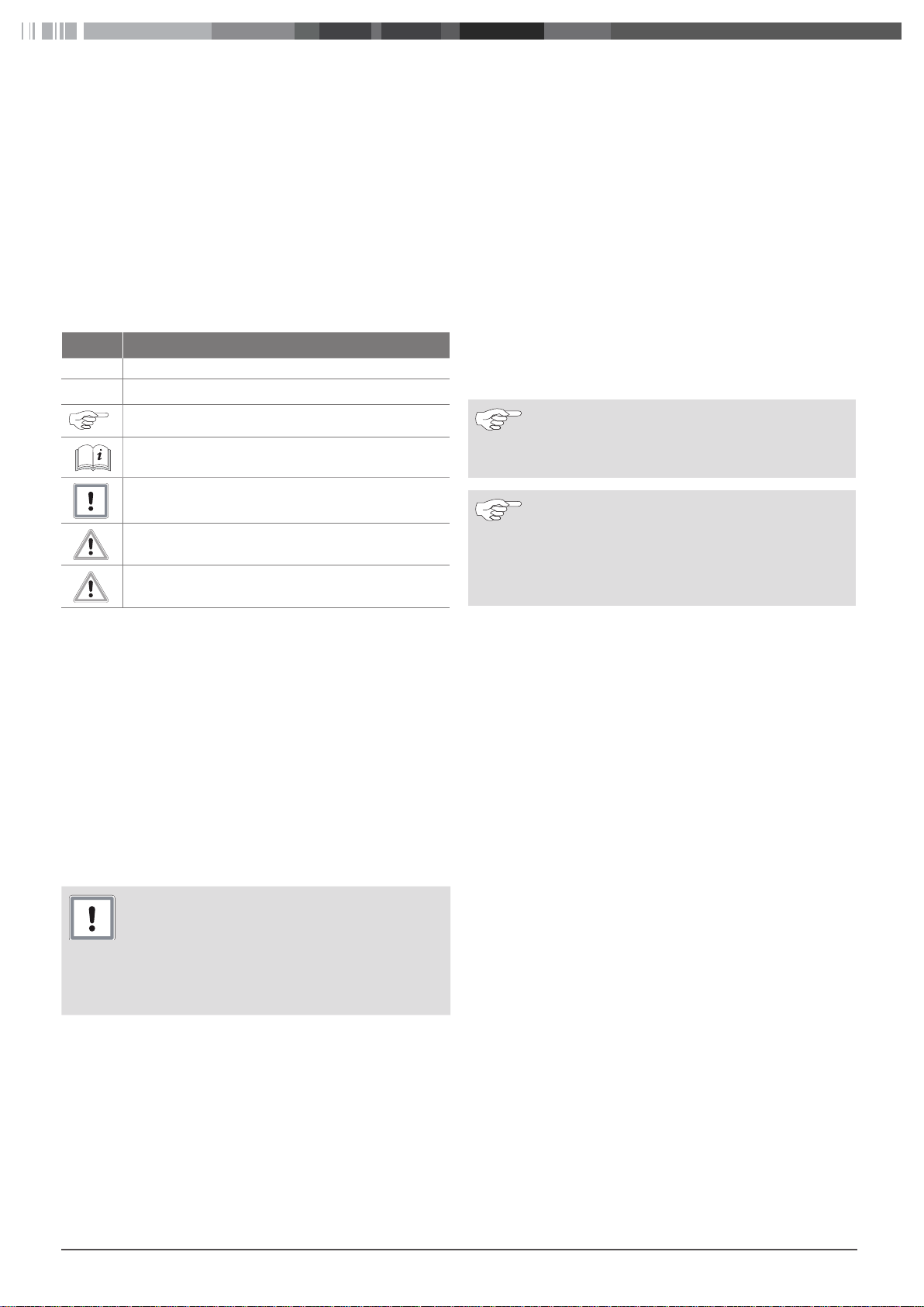
Fig. 01: Control element
The displays shown in this manual considers standard settings and programming of the control element.
3.1 Lock and unlock buttons
The keypad of the control element can be locked / unlocked with the following key combination:
Lock and unlock buttons
X Press the "Up" and "Down" button and hold for
several seconds:
–
The display shows "PoF", display is locked.
–
The display shows “Pon”, display is unlocked.
3.2 Cooling compartment temperature
3.3 Service levels
The control element has an extensive set of parameters to regulate and control the refrigeration process. The parameters are split
in 2 levels:
■
Level 1
■
Level 2
Access the Service Levels as follows:
st
Enter programming mode, 1
T
X Press the "SET" and "Down" button and hold for
3 seconds:
–
The menu shows “LS” (1
–
Symbol °C or °F starts blinking.
Enter programming mode, 2
T
X Press the “SET” and “Down” button and hold for
3 seconds, (1
X Release the keys.
X Press the “SET” and “Down” button again and
hold for 7 seconds:
–
The menu shows “PR2” (2
X Release the keys:
–
Displays shows the HY parameter.
–
Symbol °C or °F starts blinking.
Return to room temperature display
T
X Press the "SET" and "Up" button and hold for
several seconds.
st
level).
level
st
level).
nd
nd
level
level).
3.2.1 View cooling compartment set-point
X Press the “Set” button and release immediately.
SET
SET
X Press „Set“ again or the current value measured
in the cooling compartment is shown after 5 seconds.
3.2.2 Set the cooling compartment temperature
X Press the “Set” button and hold for 2 seconds.
SET
–
The current set-point is displayed
–
LED flashes
X Press "Up" and "Down" button to set the cooling
compartment set-point
SET
The display with the temperature set-point flashes for several seconds. Then it shows the temperature measured in the cooling
compartment.
X To save the cooling compartment set-point press
the "Set" button or wait for at least 15 seconds.
See chapter „4 Parameter settings in 1st / 2nd level menus“ for
more information.
3.4 Service indicator
The control element indicates when service is necessary. The service interval is based on the total operating hours of the refrigeration system. See chapter „5 Set and reset the service interval“ for
more information.
3.5 The programming tool or “hot key”
You can program the control element quickly or restore parameter
settings with help of a programming tool, called the “hot key. See
chapter „6 The programming tool or “hot key”“ for more information.
Frigo Top 10 - 43 | Pordoi 2000 - 4000 4
Page 5
3.6 Hours of compressor operation
There is a counter (in hours) that saves the compressor operation
hour count. The resolution is 1 hour and the range goes from 0 to
50.000 hours. Saving interval: 5min.
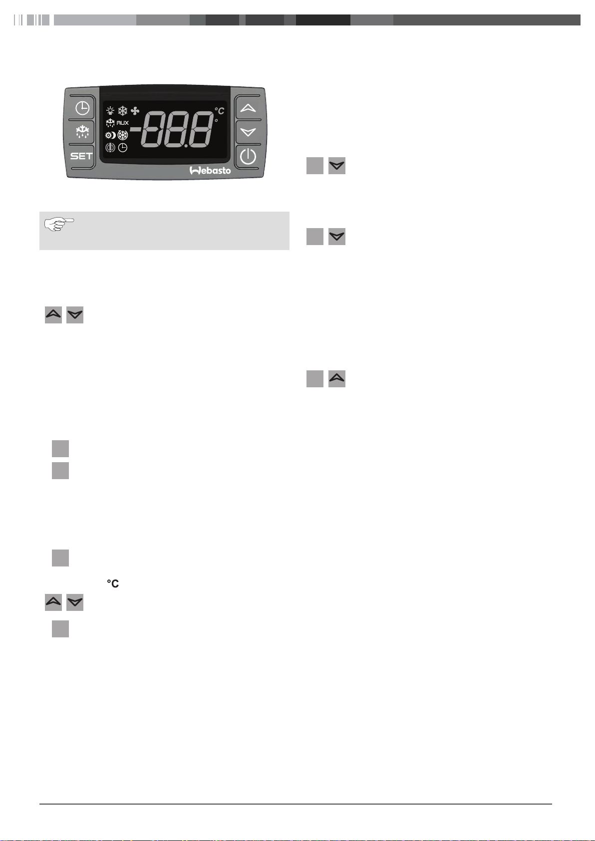
Example:
If the saved value is 1511 hours of operation, the first time the
button is pressed “001” (thousands) is displayed. The second time
the “Clock” button is pressed “-511” (units) is displayed.
X Press the “Clock” button:
–
The compressor operation count, in hours,
appears on the display. The first value displayed
indicates the thousands.
X Press the “CLOCK” button again:
–
The units of the compressor operation count
appears on the display; preceded by a minus
sign.
Fig. 02: ”Thousands” indication
Fig. 03: ”Units” indication
Repeatedly pressing the “Clock” button toggles between the two
values.
During display of the compressor operating hours only the “Clock”
LED remains on.
When no key is pressed for 3s, the instrument goes back to normal display.
The user cannot reset the saved value. Only Dixell
can reset it, using a special reset procedure.
Frigo Top 10 - 43 | Pordoi 2000 - 4000 5
Page 6
4 Parameter settings in 1st / 2nd level menus
T
T
T
T
T
T
For more information and overviews:
■
Chapter „10.3 Parameter description“
■
Chapter „10.4 Standard parameter settings“
For sake of overview the parameters are grouped per function:
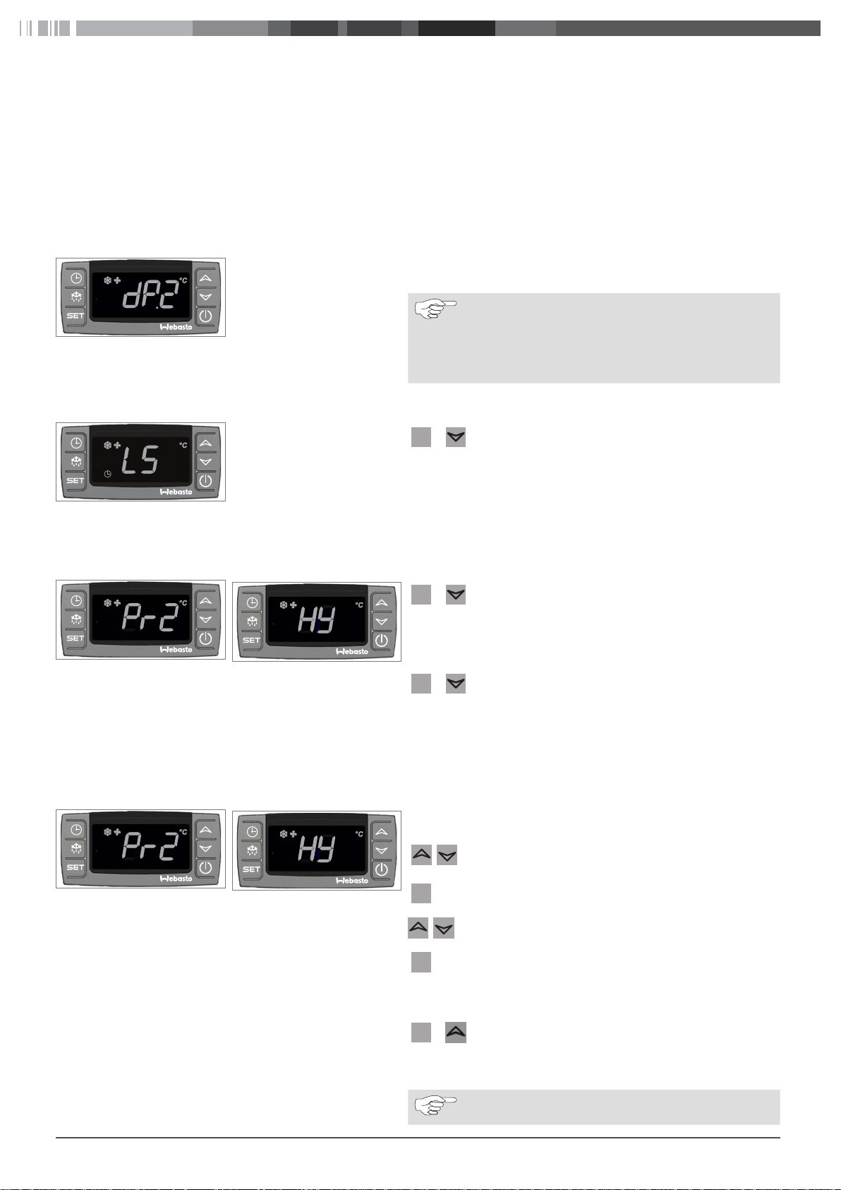
Fig. 04: Level 1 parameter in service
level 2
4.1 Entering the 1st service level
Fig. 05: First parameter of the 1st
level service menu
1. Regulation
2. Display
3. Defrost
4. Fans
In service level 2 the decimal point is on to show that the parameter
is a level 1 parameter.
Parameters can be moved from one level to the other,
but it is better to keep the parameters in their original
level.
XPress “Set” and “Up” to move a 2nd level parameter
to service level 1 and visa versa.
+ XPress “Set” + “Down” and hold for 3 seconds.
SE
–
The menu shows “LS”, the first parameter of the 1
service level.
–
The degree symbol starts blinking.
5. Alarms
6. Condenser temperature alarm
7. Digital input
8. Others
st
4.2 Entering the 2nd service level
Fig. 06: 2nd level service menu
Fig. 07: First parameter of the 2nd
level service menu
4.3 Change a parameter setting
Fig. 08: 2nd level service menu
Fig. 09: First parameter of the 2nd
level service menu
+ XPress “Set” + “Down” and hold for 3 seconds.
SE
–
The menu shows “LS” (First parameter of the 1
service level).
–
The degree symbol starts blinking.
+
SE
XPress “Set” + “Down” again and hold for 7 seconds.
–
The menu shows “Pr2” (2nd service level).
XRelease the keys.
–
The menus shows “HY”, the first parameter of the
2nd service level.
XEnter the desired service menu.
XSelect the required parameter with the “Up” or
“Down” key.
SE
XPress “Set”.
XSelect the required value with the “Up” or “Down”
key.
SE
XPress “Set” to store the selected value.
st
4.4 Exit a service menu
+ XPress “Set” + “Up” and hold for several seconds.
SE
or
XWait 15s without pressing a key
A set value is stored even when you exit the service
menu by means of waiting 15s without pressing a key.
Frigo Top 10 - 43 | Pordoi 2000 - 4000 6
Page 7

5 Set and reset the service interval
T
T
T
5.1 Enter the service interval menu
The instructions below describe how to change the settings via the
control element.
Fig. 10: 1st level Fig. 11: Service menu
+
SE
+
XPress “Set” + “Down” and hold for 3 seconds.
XPress “Up” + “Down” and hold for 7 seconds.
5.2 Switch between reset interval and change interval
/ XPress “Up” or “Down” to switch between:
Fig. 12: SEr: Change interval Fig. 13: rSt: Reset interval
5.3 Reset the service interval
Make sure that the screen shows “rSt”
3
ATTENTION
Do not reset the service interval without servicing
the refrigeration system.
Fig. 14: Reset interval, No Fig. 15: Reset interval, Yes
Result: System failure could occur due to insufficient
maintenance.
XReset of the service interval is only allowed after ser-
vice has been carried out.
–
The menu shows “LS” (1
–
The degree symbol starts blinking.
–
The menu shows “SEr” (Service menu).
–
“SEr” change interval
–
“rSt” reset interval
st
service level).
More information about service is available in “Service
handbook and system data” supplied with the system.
SE
SE
XPress “Set”.
–
The screen shows “n”.
XPress “Up” to switch to “y”.
XPress “Set” to reset the service interval.
–
“rSt” starts blinking.
–
The clock symbol disappears.
–
Screen shows “SEr”.
–
After approx. 10 s the display turns back to the
operating menu.
Frigo Top 10 - 43 | Pordoi 2000 - 4000 7
Page 8

5.4 Change the service interval
T
SE
Make sure that the screen shows “SEr”
3
The standard service interval is 2.000 hr.
XPress “Set”
SE
Fig. 16: Interval setting at 2.000 hr
/
T
–
The screen shows the actual service interval
XPress “Up” or “Down” to increase or decrease the
service interval value:
0=Service indicator is disabled
100=1.000hr;
150=1.500hr;
200=2.000hr;
XPress “Set” to confirm a service interval.
–
“SEr” starts blinking.
–
Screen shows “SEr”.
–
After approx. 10 s the display turns back to the
operating menu.
250=2.500hr;
300=3.000hr.
6 The programming tool or “hot key”
You can program the control element quickly or restore parameter with help of a programming tool, called the “hot key. The hot key
has 2 functions:
■
Download parameters from the hot key into the control element.
■
Upload parameters from the control element into the hot key.
Uploading parameters from the control element into the hot key provides a back up for eventual restoring parameter settings or to program other control elements with the same set of parameters quickly.
6.1 General
Provide access to the backside of the control element or remove
3
the control element from its mounting panel.
XYou insert a hot key in the slot at the back of the control element.
Fig. 17: Slot hot key
Fig. 18: Upload / download error in-
dication
6.2 Download parameters to the control element
Mind the right position of the hot key!
The control element shows “Err” in case the download
or upload failed.
■
Switch the control element off and on again to
restart the download or upload.
or
■
Remove the hot key to stop operation.
XSwitch off the control element.
XInsert a hot key in the slot at the back of the control
element.
Frigo Top 10 - 43 | Pordoi 2000 - 4000 8
Page 9

Fig. 19: Download indication Fig. 20: End of download cycle
6.3 Upload parameters to the hot key
Fig. 21: Upload indication Fig. 22: End of upload cycle
XSwitch on the control element:
–
Download starts and the parameters of the hot key
are loaded into the control element.
–
The display of the control element shows “doL”
during the download.
–
At the end of the download cycle the display shows
“End”.
–
After 10s the control element restarts, and uses the
new parameters.
XRemove the hot key.
Program the control element as desired with the keys on the front.
3
Leave the control element on.
3
XInsert a hot key in the slot at the back of the control element.
X Press the “Up” key.
–
Upload starts.
–
Control element shows “upL”.
–
At the end of the upload cycle the display shows
“End”.
XPress “SET” to finish the upload cycle.
XSwitch off the control element.
XRemove the hot key.
XSwitch the system on again.
Frigo Top 10 - 43 | Pordoi 2000 - 4000 9
Page 10

7 Error messages
Error messages on the display indicate malfunctions in the refrigeration system. A message is displayed until the cause is rectified.
Code Possible cause Measure
P1 Fault on the room temperature sensor Depending on parameter setting in the control unit the refrigeration
system keeps operating or switches off.
XCheck the connections before replacing the sensor.
XContact a Webasto service partner.
P2 Fault on the evaporator sensor The refrigeration system keeps operating but the error will continue
to be displayed.
XCheck the connections before replacing the sensor.
XContact a Webasto service partner.
HA Maximum temperature alarm Temperature in cooling compartment is too high.
LA Minimum temperature alarm Temperature in cooling compartment is too low.
POF Not an error.
The keyboard is locked
CA Alarm pressure switch.
Battery alarm, low voltage
Only valid for Rolle and Frigo Top 10 I-ES
XPress and simultaneously and hold for several seconds to
unlock the keyboard.
XSwitch off system.
XContact a Webasto service partner.
8 Technical support and customer service
Do you have any technical questions or problem with the device?
National phone numbers of our representatives are provided on the following website: www.webasto.com.
9 Disposal
When you eventually decommission the system, please dispose of the individual components properly at a recycling centre.
Frigo Top 10 - 43 | Pordoi 2000 - 4000 10
Page 11

10 Annex
10.1 Technical data
Description Data Description Data
Power supply 12/24VDC Operating temperature 0 – 60°C (32 – 140°F)
Power consumption 3VA Storage temperature -30-85 °C (-22 – 185°F)
Protection IP20 Relative humidity 20 – 80%, non-condensing
Frontal protection IP65 Measuring and regulating
range:
Digital input Potential free contact NTC probe -40 – 110°C (-40 – 230°F)
Relay outputs: PTC probe -50 – 150°C (-58 – 302°F)
Compressor 8(3)A, 16(6)A, or 20(8)A,
250VAC
Defrost 8(3)A, 250VAC
Fan 8(3), 250VAC
60
32
F
74
29
Fig. 23:
Control element dimensions
71
10.2 (Typical) 12/24VDC wiring and connections
9
10 11 12
Max.
16 A
1 2 3 4 5 7 8
13
Legenda:
1. Line
2. Defrost
3. Not connected
4. Fan
5. Compressor
6. -
7. Supply 12/24V
8. Supply 12/24V
9. Digital input
10. Evaporator temperature sensor
11. Common
12. Room temperature sensor
13. Hot key plug
Fig. 24: Wiring connections
Frigo Top 10 - 43 | Pordoi 2000 - 4000 11
Page 12

10.3 Parameter description
10.3.1 Regulation
Label Description Range
HY Intervention differential for set point:
Compressor Cut IN is Set Point Plus Differential (HY).
Compressor Cut OUT is when the temperature reaches the set point.
LS Minimum set point:
Sets the minimum acceptable value for the set point.
US Maximum set point:
Sets the maximum acceptable value for set point.
ot Thermostat probe calibration: allows to adjust the possible offset of the
thermostat probe.
P2P Evaporator probe presence:
n = not present: time stops the defrost cycle;
y = present: temperature stops the defrost cycle.
oE Evaporator probe calibration:
Allows to adjust possible offset of the evaporator probe.
odS Outputs activation delay at start up:
This function is enabled at the initial start up of the instrument and inhibits
any output activation for the period of time set in the parameter.
db Dead band (= neutral zone); allows the system to control the cell tempera-
ture to higher or lower temeratures compared to the set temperature. To
be used in case of heating kit.
n = neutral zone disabled; cooling only
y = neutral zone enabled; heating kit installed
AC Anti-short cycle delay: minimum interval between the compressor stop and
the following restart.
CCt Compressor ON time during continuous cycle:
Allows to set the length of the continuous cycle: compressor stays on without interruption for the CCt time. Can be used, for instance, when the room
is filled with new products.
CCS Set point for continuous cycle: it sets the set point used during the continu-
ous cycle.
Con Compressor ON time with faulty probe: time during which the compressor
is active in case of faulty thermostat probe.
With Con = 0 the compressor is always OFF.
CoF Compressor OFF time with faulty probe: time during which the compressor
is OFF in case of faulty thermostat probe.
With COF = 0 the compressor is always active.
0.1 – 25.5 °C (1 – 255 °F) 2
- 50 °C – SET (-58 °F – SET) 1
SET – 110 °C (SET – 230 °F) 1
-12 – 12 °C (-120 – 120 °F) 2
-12 – 12 °C (-120 – 120 °F). 2
0 – 255min 2
0 – 50min 2
0.0 – 24.0h; res. 10min 2
-50 – 150 °C (-58 – 302 °F) 2
0 – 255min 2
0 – 255min 2
Program level
1 2
1
2
10.3.2 Display
Label Description Range
CF Temperature measurement unit:
°C = Celsius; °F = Fahrenheit.
ATTENTION
When the measurement unit is changed the SET point and the
values of the parameters HY, LS, US, Ot, ALU and ALL have to
be checked and modified if necessary).
rES Display resolution (for °C only):
in = 1 °C;
dE = 0.1 °C; allows decimal point display.
Frigo Top 10 - 43 | Pordoi 2000 - 4000 12
Program level
1 2
2
2
Page 13

Label Description Range
Lod Instrument display : selects which probe is displayed by the instrument:
P1 = Thermostat probe;
P2 = Evaporator probe.
10.3.3 Defrost
Program level
1 2
2
Label Description Range
tdF Defrost type:
EL = electrical heater;
in = hot gas
dtE Defrost termination temperature: (Enabled only when EdF=Pb).
Sets the temperature measured by the evaporator probe, which causes the
end of defrost.
idF Interval between defrost cycles:
Determines the time interval between the beginning of two defrost cycles.
MdF (Maximum) length for defrost:
When P2P = n, (no evaporator probe: timed defrost) it sets the defrost duration,
when P2P = y, (defrost end based on temperature) it sets the maximum
length for defrost.
dSd Start defrost delay:
This is useful when different defrost start times are necessary to avoid overloading the plant.
dFd Temperature displayed during defrost:
rt = real temperature;
it = temperature at defrost start;
SEt = set point;
dEF = “dEF” label
dAd MAX display delay after defrost:
Sets the maximum time between the end of defrost and the restarting of
the real room temperature display.
Fdt Drip time: time interval between reaching defrost termination temperature
and the restoring of the control’s normal operation. This time allows the
evaporator to eliminate water drops that might have formed due to defrost.
dPo First defrost after start-up:
y = immediately;
n = after the IdF time
dAF Defrost delay after continuous cycle: time interval between the end of the
fast freezing cycle and the following defrost related to it.
-50 – 50 °C (-58 – 122 °F) 1
0 – 120h 1
0 – 255min 1
0 – 99min 2
0 – 255min 2
0 – 120min 1
0 – 23.5h 2
Program level
1 2
2
2
2
10.3.4 Fans
Label Description Range
FnC Fans operating mode:
C-n= runs with the compressor, OFF during defrost;
o-n = continuous mode, OFF during defrost;
C-Y = runs with the compressor, ON during defrost;
o-Y = continuous mode, ON during defrost;
Fnd Fans delay after defrost: Time interval between end of defrost and evapora-
tor fans start.
Frigo Top 10 - 43 | Pordoi 2000 - 4000 13
0 – 255min 2
Programm level
1 2
1
Page 14

Label Description Range
FSt Fans stop temperature: setting of temperature, detected by evaporator
probe, above which fans are always OFF.
Fon Fans on time: with FnC = C_n or C_y, (fan activated in parallel with the
compressor). It sets the evaporator fan ON cycling time when the compressor is off. With Fon = 0 and FOF ≠ 0, the fans are always off. With Fon = 0
and FOF = 0 the fans are always off.
FOF Fan off time: with FnC = C_n or C_y, (fan activated in parallel with the com-
pressor). It sets the evaporator fan OFF cycling time when the compressor
is off. With Fon = 0 and FOF ≠ 0, the fans are always off. With Fon = 0 and
FOF = 0 the fans are always off.
-50 – 50 °C (122 °F) 1
0 – 15min 2
0 – 15min 2
10.3.5 Alarms
Programm level
1 2
Label Description Range
ALC Temperature alarms configuration:
Ab = absolute temperature: alarm temperature is given by the ALL or ALU
values.
rE = temperature alarms are referred to the set point.
Temperature alarm is enabled when the temperature exceeds the “SET+ALU” or “SET-ALL” values.
ALU Maximum temperature alarm: when this temperature is reached the alarm
is enabled, after the “ALd” delay time.
ALL Minimum temperature alarm: when this temperature is reached the alarm
is enabled, after the “ALd” delay time.
ALd Temperature alarm delay: time interval between the detection of an alarm
condition and alarm signalling.
dAo Exclusion of temperature alarm at startup: time interval between the detec-
tion of the temperature alarm condition after instrument power on and
alarm signalling.
SE Regular service has to be performed (x10 hours). 2
SET – 110 °C (SET – 230 °F) 2
-50.0 – SET °C (-58 – 230 °F) 2
0 – 255min 2
0.0 min to 23.5h 2
Program level
1 2
10.3.6 Digital input
Label Description Range
i1P Digital input polarity:
oP: the digital input is activated by opening the contact;
CL: the digital input is activated by closing the contact.
i1F Digital input configuration:
EAL = external alarm: “EA” message is displayed;
bAL = serious alarm “CA” message is displayed.
PAL = pressure switch alarm, “CA” message is displayed;
dor = door switch function;
dEF = activation of a defrost cycle;
LHt = not enabled;
Htr = kind of action inversion (cooling – heating)
AUS = not enabled;
FAn = not set it
ES = energy saving.
Program level
1 2
2
2
2
Frigo Top 10 - 43 | Pordoi 2000 - 4000 14
Page 15

Label Description Range
did Digital input alarm delay: with i1F = EAL or i1F = bAL digital input alarm de-
lay: delay between the detection of the external alarm condition and its signalling.
With i1F = dor: door open signalling delay
With i1F = PAL: time for pressure switch function: time interval to calculate
the number of the pressure switch activation.
nPS Pressure switch number: Number of activation of the pressure switch, dur-
ing the “did” interval, before signalling the alarm event (I2F = PAL).
If the nPS activation in the did time is reached, switch off and on the instrument to restart normal regulation.
OdC Compressor and fan status when door open:
no = normal;
Fan = Fan OFF;
CPr = Compressor OFF;
F_C = Compressor and fan OFF.
0 – 255min 2
0 – 15 2
10.3.7 Other
Program level
1 2
2
Label Description
PbC Type of probe: it allows to set the kind of probe used by the instrument:
PbC = PBC probe,
ntC = NTC probe.
OnF On/Off key enabling:
no = disabled.
OFF = enabled.
ES = not set it.
dP1 First probe display. 1
dP2 Second probe display. 1
rEL Software release for internal use. 2
Ptb Parameter table code: read only. 2
Program level
1 2
2
2
Frigo Top 10 - 43 | Pordoi 2000 - 4000 15
Page 16

10.4 Standard parameter settings
The standard parameter settings differ depending on the refrigerant. The tables below show the standard settings for refrigerant:
■
R134a
■
R134a and system with defrost
■
R404A
Making changes to these settings affects the functional safety of the system. Only make changes to the settings if you are familiar with
the outcome!
10.4.1 Regulation
Label Description
HY Differential 2 2 2 2
LS Minimum set point 0 0 -20 1
US Maximum set point 30 30 30 1
ot Thermostat probe calibration 0 0 0 2
P2P Evaporator probe presence y y y 1
oE Evaporator probe calibration 0 0 0 2
OdS Outputs delay at start up 0 0 0 2
db Dead band (neutral zone) n n n
AC Anti-short cycle delay 1 1 1 2
CCt Continuous cycle duration 0 0 0 2
CCS Set point for continuous cycle 0 0 0 2
COn Compressor ON time with faulty probe 15 15 15 2
CoF Compressor OFF time with faulty probe 30 30 30 2
R134a R134a with defrost R404A 1 2
Refrigerant Program level
2
y in case of
heating kit
10.4.2 Display
Label Description
CF Temperature measurement unit °C °C °C 2
rES Resolution dE dE dE 2
Lod Probe displayed P1 P1 P1 2
R134 R134a with defrost R404A 1 2
Refrigerant Program level
10.4.3 Defrost
Label Description
tdF Defrost type EL in in 2
dtE Defrost termination temperature 2 5 5 1
idF Interval between defrost cycles 1 3 3 1
MdF (Maximum) length for defrost 8 5 5 1
dSd Start defrost delay 0 0 0 2
dFd Displaying during defrost dEF dEF dEF 2
dAd MAX display delay after defrost 1 1 1 2
Fdt Draining time 1 1 1 1
dPo First defrost after start-up n n n 2
dAF Defrost delay after fast freezing 0 0 0 2
R134 R134a with defrost R404A 1 2
Refrigerant Program level
Frigo Top 10 - 43 | Pordoi 2000 - 4000 16
Page 17

10.4.4 Fans
Label Description
FnC Fan operating mode C-y C-y C-n 1
Fnd Fan delay after defrost 0 0 2 2
FSt Fan stop temperature 50 50 50 1
Fon Fan on time with compressor off 0 0 0 2
FOF Fan off time with compressor off 0 0 0 2
R134 R134a with defrost R404A 1 2
Refrigerant Program level
10.4.5 Alarms
Label Description
ALC Temperature alarms configuration Ab Ab Ab 2
ALU Maximum temperature alarm 110 110 110 2
ALL Minimum temperature alarm -50 -50 -50 2
ALd Temperature alarm delay 15 15 15 2
dAo Delay of temperature alarm at start up 1.3 1.3 1.3 2
SE Regular service has to be performed (x10 hours) 200 200 200 2
R134 R134a with defrost R404A 1 2
Refrigerant Program level
10.4.6 Digital input
Label Description
i1P Digital input polarity cL cL cL 2
i1F Digital input configuration dor dor PAL 2
did Digital input alarm delay 15 15 10 2
nPS Number of activation of pressure switch 15 15 5 2
odc Compress and fan status with open door no no no 2
R134 R134a with defrost R404A 1 2
Refrigerant Program level
10.4.7 Other
Label Description
PbC Kind of probe ntC ntC ntC 2
OnF on/off key enabling oFF oFF oFF 2
dP1 Room probe display / / / 1
dP2 Evaporator probe display / / / 1
rEL Software release … … … 2
Ptb Map code / / / 2
R134 R134a with defrost R404A 1 2
Refrigerant Program level
Frigo Top 10 - 43 | Pordoi 2000 - 4000 17
Page 18

In multilingual versions the English language is binding.
The telephone number of the respective country can be obtained from the Webasto service point flyer or the homepage of your respective Webasto
country representative.
Im Fall einer mehrsprachigen Version ist Englisch verbindlich.
Die Telefonnummer des jeweiligen Landes entnehmen Sie bitte dem Webasto Servicestellenfaltblatt oder der Webseite Ihrer jeweiligen Webasto
Landesvertretung.
Dans le cas d’une version rédigée en plusieurs langues, l’anglais est alors la langue qui fait foi.
Pour trouver le numéro de téléphone du pays concerné, veuillez consulter le dépliant des points-service Webasto ou la page web de la représentation
Webasto de votre pays.
Nelle versioni multilingue la lingua inglese è vincolante.
I recapiti telefonici dei diversi Paesi sono riportati nel pieghevole relativo ai centri di assistenza Webasto oppure nel sito web del proprio rappresentante
di riferimento Webasto.
En documentos multilingües, se considera vinculante el texto en inglés.
Puede encontrar el número de teléfono del país correspondiente en el folleto de centros de servicio de Webasto o en la página web del representante de
Webasto en su país.
Ident No. • 6243665A • 05/18 •Errors and omissions excepted •© Webasto Thermo & Comfort SE 2018
Webasto Thermo & Comfort SE
Postfach 1410
82199 Gilching
Germany
Company address:
Friedrichshafener Str. 9
82205 Gilching
Germany
www.webasto.com
 Loading...