

Page 1

Integriertes Heizgerät
Integrated Heater
Riscaldatore integrato
Einbauanweisung
Installation Instructions
Istruzioni di montaggio
DUAL TOP
03/2009
RHA 100
(für Trinkwasser)
(for drinking water)
(per acqua potabile)
Page 2

Contents
GB
Contents
1 General .............................................................................................. 1
2 Statutory regulations governing installation ................................. 2
2.1. Extract from Directive 2001/56/EC Annex VII ........................................ 2
3 Use of the integrated air / water heater ........................................ 4
4 Additional safety instructions ......................................................... 5
5 Installation example ........................................................................ 6
6 Heater installation ............................................................................ 8
6.1. General ............................................................................................... 8
6.2. Dual Top connections ........................................................................ 8
6.3. Installation location .............................................................................. 9
6.4. Connecting the wiring harness .......................................................... 11
6.5. Installing the heater ........................................................................... 12
7 Identification plate ......................................................................... 14
8 Hot water system ........................................................................... 15
9 Hot air system ................................................................................. 17
9.1. Heating air intake .............................................................................. 18
9.1.1. General .............................................................................................. 18
9.1.2. Installation.......................................................................................... 18
9.2. Hot air distribution ............................................................................. 20
10 Cooling air system .......................................................................... 22
10.1. Installation ......................................................................................... 22
11 Boiler drainage and pressure relief system .................................. 23
12 Fuel supply ...................................................................................... 24
12.1. General ............................................................................................. 24
12.2. Fuel pump ..........................................................................................25
12.2.1. Installation location .............................................................................25
12.2.2. Installation and attachment .................................................................25
12.3. Fuel extraction. ...................................................................................26
12.4. Fuel lines ............................................................................................27
12.4.1. Routing ............................................................................................... 27
12.4.2. Connecting two pipes with a hose ......................................................28
12.5. Fuel filter ............................................................................................28
13 Combustion air supply .................................................................... 29
13.1. General ..............................................................................................29
13.2. Combustion air intake line ................................................................29
14 Exhaust system ................................................................................31
14.1. General ..............................................................................................31
14.2. Exhaust line ........................................................................................ 32
15 Electrical connections ...................................................................... 35
15.1. Supply voltage connection ..................................................................36
15.2. Interior temperature sensor ................................................................37
15.3. Control Panel connection ...................................................................38
16 Circuit diagram ..............................................................................40
16.1. Legend for circuit diagram ..................................................................41
17 Starting the heater for the first time ............................................. 42
18 Fault lock-out ................................................................................... 43
19 Validation and commissioning .......................................................46
20 Technical data ..................................................................................47
20.1. Fuel for Dual Top RHA 100 .................................................................47
20.2. Technical data ................................................................................... 48
II
Page 3

Dual Top General
1 General
For installation and repair of a Webasto Dual Top RHA 100 integrated
heater you will need technical documentation, a special training by
Webasto, special tools and special equipment.
Installation and all other jobs carried out by not certified persons can harm
you, the Dual Top and the vehicle. In that case, Webasto will refuse all
liability.
Do NOT install or repair a Webasto Dual Top RHA 100 heater, if you have
not successfully finished the training by Webasto for acquiring the
necessary technical skills. Do NOT install or repair the product, if you do not
have the necessary technical documentation, tools or equipment.
ALWAYS follow the Webasto installation and service instructions and mind
all warning indications.
Only use genuine Webasto parts. See the Webasto air and water heaters
accessory catalogue and Webasto camping catalogue.
Webasto does not take over any liabilities for defects or damages caused
by for installation untrained personnel.
1
Page 4

Statutory regulations governing installation Dual Top
2 Statutory regulations governing installation
The Dual Top RHA 100 heater has been type-tested and approved in
accordance with EC Directives 72/245/EEC (EMC) and 2001/56/EC (heater)
with the following EC permit numbers:
e1 03 5000
e1 00 0195
Installation is governed above all by the provisions in Annex VII of
Directive 2001/56/EC.
NOTE:
The provisions of these Directives are binding within the territory
governed by EU Directive 70/156/EEC and should similarly be
observed in countries without specific regulations.
See chapter 2.1, "Extract from Directive 2001/56/EC Annex VII"
The Dual Top complies with all applicable standards for this type of
product.
When intalling the Dual Top heater and related components, make sure to
follow all local regulations (e.g. 98/83/EC, DIN 2001-2, DVGW W 291).
Make sure that during the installation the legal requirements for the
permits of the vehicle are not violated, in particular for the heater fixation
and the routing of the exhaust lines.
IMPORTANT
Failure to follow the installation instructions and the notes contained
therein will lead to all liability being refused by Webasto. The same applies
if repairs are carried out incorrectly or with the use of parts other than
genuine spare parts. This will result in the invalidation of the type approval
for the heater and therefore of its homologation / EC type licence.
NOTE:
For vehicles with an EU permit, no entry in accordance with § 19
Sub-Section 4 of Annex VIII b to the Road Traffic Act is required.
2.1. Extract from Directive 2001/56/EC Annex VII
Start of extract.
ANNEX VII
REQUIREMENTS FOR COMBUSTION HEATERS AND THEIR
INSTALLATION
1. GENERAL REQUIREMENTS
1.7.1. A clearly visible tell-tale in the operator's field of view shall
inform when the combustion heater is switched on or off.
2. VEHICLE INSTALLATION REQUIREMENTS
2.1. Scope
2.1.1. Subject to paragraph 2.1.2, combustion heaters shall be
installed according to the requirements of this Annex.
2.1.2. Vehicles of category O having liquid fuel heaters are
deemed to comply with the requirements of this Annex.
2.2. Positioning of heater
2.2.1. Body sections and any other components in the vicinity of
the heater must be protected from excessive heat and the
possibility of fuel or oil contamination.
2
Page 5

Dual Top Statutory regulations governing installation
2.2.2. The combustion heater shall not constitute a risk of fire,
even in the case of overheating. This requirement shall be deemed
to be fulfilled if the installation ensures an adequate distance to all
parts and suitable ventilation, by the use of fire resistant materials
or by the use of heat shields.
2.2.3. In the case of M2 and M3 vehicles, the heater must not be
positioned in the passenger compartment. However, an
installation in an effectively sealed envelope which also complies
with the conditions in paragraph 2.2.2 may be used.
2.2.4. The label (see chapter 7, "Identification plate") referred to
in paragraph 1.4, or a duplicate, must be positioned so that it can
be easily read when the heater is installed in the vehicle.
2.2.5. Every reasonable precaution should be taken in positioning
the heater to minimise the risk of injury and damage to personal
property.
2.3. Fuel supply
2.3.1. The fuel filler must not be situated in the passenger
compartment and must be provided with an effective cap to
prevent fuel spillage.
2.3.2. In the case of liquid fuel heaters, where a supply separate
to that of the vehicle is provided, the type of fuel and its filler point
must be clearly labelled.
2.3.3. A notice, indicating that the heater must be shut down
before refuelling, must be affixed to the fuelling point. In addition
a suitable instruction must be included in the manufacturer's
operating manual.
2.4. Exhaust system
2.4.1. The exhaust outlet must be located so as to prevent
emissions from entering the vehicle through ventilators, heated air
inlets or opening windows.
2.5. Combustion air inlet
2.5.1. The air for the combustion chamber of the heater must not
be drawn from the passenger compartment of the vehicle.
2.5.2. The air inlet must be so positioned or guarded that blocking
by rubbish or luggage is unlikely.
2.6. Heating air inlet
2.6.1. The heating air supply may be fresh or recirculated air and
must be drawn from a clean area not likely to be contaminated by
exhaust fumes emitted either by the propulsion engine, the
combustion heater or any other vehicle source.
2.6.2. The inlet duct must be protected by mesh or other suitable
means.
2.7. Heating air outlet
2.7.1. Any ducting used to route the hot air through the vehicle
must be so positioned or protected that no injury or damage could
be caused if it were to be touched.
2.7.2. The air outlet must be so positioned or guarded that
blocking by rubbish or luggage is unlikely.
End of extract.
3
Page 6

Use of the integrated air / water heater Dual Top
3 Use of the integrated air / water heater
The Webasto Dual Top RHA 100 integrated air / water heater has been
designed to heat and to provide hot water (drinking water) in motor
homes and similar vehicles.
The heater operates independently of the engine and is connected to the
fuel tank and the electrical system of the vehicle.
It is not designed for heating vehicles transporting hazardous substances.
4
Page 7

Dual Top Additional safety instructions
4 Additional safety instructions
• If the Dual Top falls to the floor, it must be returned to Webasto for a
safety inspection/repair.
• It is not allowed to paint or re-paint the Dual Top heater partly or
completely.
5
Page 8

Installation example Dual Top
5 Installation example
16
15
14
13
12
11
10
9
8
Fig. 1: Installation example for heater in camper
6
1
2
3
4
5
6
7
Page 9

Dual Top Installation example
1 Interior temperature sensor
2 Water lines
3 Webasto Dual Top RHA 100 heater
4 Cooling air intake adapter
5 Webasto dual adapter
6 Combustion air intake silencer
7 Exhaust silencer
8 Fuel tank connector
9Fuel tank
10 Fuel pump
11 LED dashboard
12 Water pump
13 Water tank
14 Cooling air outlet
15 Hot air distribution
16 Control Panel
7
Page 10

Heater installation Dual Top
6 Heater installation
6.1. General
IMPORTANT
The regulations specified in chapter 2, "Statutory regulations governing installation" must be adhered to.
NOTE:
Observe the installation details specified by the manufacturer of the relevant vehicle type.
6.2. Dual Top connections
23 4 5
Fig. 2: Connections of the heater
1 Heating air inlet
2 Water inlet (cold)
3 Water outlet (hot)
4 Cooling air inlet
5 Intake cap
6 Wiring harness outlets, left and right
7 Outlet cap
8
61
78910111213
8 Exhaust outlet
9Drain valve hose
10 Pressure relief valve hose
11 Cooling air outlet
12 Fuel intake
13 Combustion air intake
Page 11

Dual Top Heater installation
6.3. Installation location
At all sides of the heater there should be at least 20 mm space.
>20
256
>20
Fig. 3: Dimensions [mm] of the heater
• Space requirement for hot air outlet > 150 mm
• Length 530 mm
• Space requirement for air inlet > 200 mm
• Width 352 mm
• Height 256 mm
• Space requirement at sides > 20 mm
• Space above the heater > 20 mm
352
Intake cap
>200
530
Outlet cap
>150
9
Page 12

Heater installation Dual Top
Find a suitable location for the heater.
Space for the heater:
• Make sure to have sufficient space at all sides of the heater.
See Fig. 3;
• Heater has to be fixed to elements of the vehicle that can withstand a
weight of 35 kg;
• All parts above the water crossing level (specified for the vehicle);
• Possibility to remove the heater;
• Possibility to access and remove the intake cap of the heater.
The heater shall be fitted on the exterior of the vehicle. Ensure that the
heater is fitted in a position where it is protected from splashing water.
Orientation of the heater:
The heater has to be mounted in a horizontal position (tolerance ± 5º),
with exhaust outlet and cooling air outlet port pointing downwards.
See Fig. 4.
+5º
-5º
Fig. 4: Required installation position
+5º
-5º
IMPORTANT
Make sure that after installation the casing of the heater is not in contact
with any parts of the vehicle body. Ensure that all moving parts can move
easily. A failure to do this may result in the hot air fan, cooling air fan or
another part blocking.
Fig. 5: Heater casing must not touch vehicle body
10
Page 13

Dual Top Heater installation
6.4. Connecting the wiring harness
Connect the wiring harness plug X11 (12 poles) to the matching
connector of the heater.
1
2
3
Fig. 6: Removal front cover
1. Intake cap
2. Intake cap fixing screws
3. Opening for wiring harness Dual Top.
Fig. 7: Connection wiring harness
11
Page 14
Heater installation Dual Top
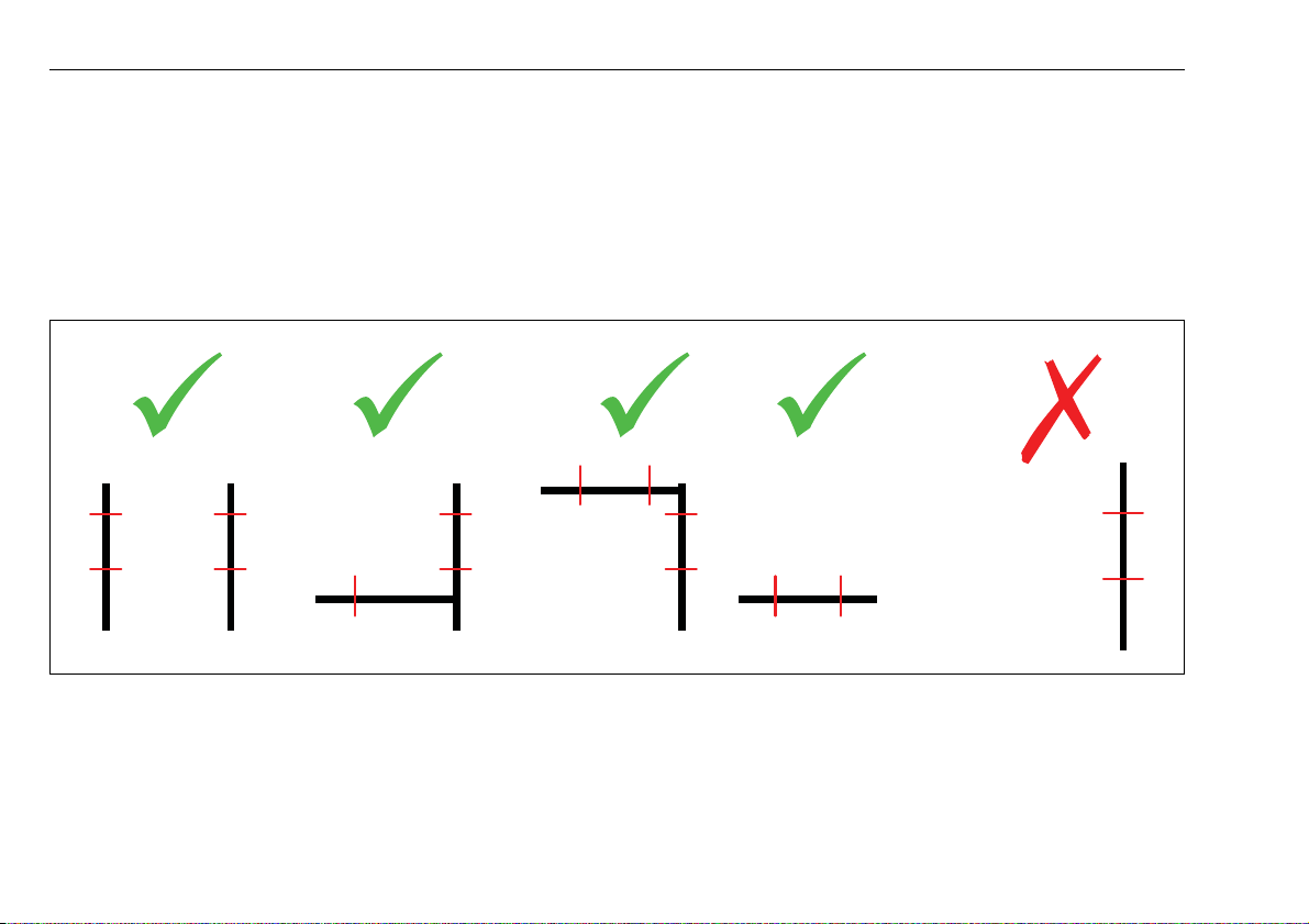
6.5. Installing the heater
• Mount the M8 hammerhead bolts in the guide rails of the heater and
use brackets to attach the heater to supporting parts of vehicle chassis.
• Vibration dampers should be used. Tighten the M8 hammerhead bolts
and nuts with a torque of 22 - 25 Nm.
• Mount heater, brackets and vibration dampers in such a way that
dampers will be compressed by the weight of the heater.
• See Webasto camping catalogue for different kinds of fixation brackets.
• At least 4 fixation points.
Fig. 8: Possible fixation methods (front view)
• Fixation of the heater only on the top or on one of the sides is not
sufficient.
• Install the heater in such a way that it will not fall from the vehicle in
case the vibration dampers fail.
See Fig. 8
12
Page 15

Dual Top Heater installation
Fig. 9: Fixation brackets and vibrations dampers (examples)
13
Page 16

Identification plate Dual Top
7 Identification plate
The identification plate must be positioned so that it cannot be damaged
and must be clearly legible when the heater is installed (otherwise a
duplicate identification plate must be used).
Inapplicable years must be erased from the identification plate and the
current year must be readable.
14
Page 17

Dual Top Hot water system
8 Hot water system
The Dual Top complies with all applicable standards for this type of
product. When intalling the Dual Top heater and related components,
make sure to follow all local regulations (e.g. 98/83/EC, DIN 2001-2,
DVGW W 291).
To connect water pipes or hoses to the Dual Top RHA 100 heater, use a
standard 10 mm pipe connector (e.g. John Guest / ASP).
• Place a thermostatic mixing valve if required.
• If no quick connection system is used, secure the lines at all connection
points in a way that they can withstand pressure and are watertight.
• Fasten the hoses in a way that they cannot be damaged (e.g using hose
clips).
1234567
Fig. 10: Water system (scheme)
1 Vehicle’s water tank
2 Water pump
3 Cold water line
4 Water outlets
5 Optional thermostatic mixing valve
6 Hot water line
7 Heater Dual Top RHA 100
Fig. 11: Water line connection (examples)
NOTE:
The internal diameter of the hot water lines should be at least 8 mm.
Always use hoses, which are resistant to pressure (at least 4 bar) and hot
water (90 ºC).
For operating the heater it is posible to use all sanitary water pumps:
– creating a pressure up to 2.5 bar;
– closed when shut off;
– min. operating pressure 1 bar.
Please see separate instructions for the use of a submergible pump.
15
Page 18

Hot water system Dual Top
Avoid the flow of water from the heater back into the vehicle’s fresh water
tank. Use one-way valves if required.
If the hot water temperature at the water outlets needs to be limited, use
a thermostatic mixing valve as an option (see Fig. 10).
When connecting to a central water supply (rural or city mains) or if using
a more powerful pump, a pressure reduction valve must always be installed
to prevent a pressure above 2.5 bar developing in the boiler.
Route water hoses as short as possible and free of kinks. All hose
connections must be secured in a way that they can withstand pressure
and are watertight (also cold water hoses)! The thermal expansion of the
water can cause pressures of up to 4 bar before the overpressure valve
reacts.
It’s recommended to route all water pipes in such a way that they descend
towards the vehicle water tank. Route intake and outlet pipes connected
to the heater in such a way that there are no syphons. So, if you drain the
boiler, you also drain the water lines.
The water lines must be routed inside the heating air intake hose. This will
avoid frozen water lines as long as the heater is operating in a proper mode
(see Operating Instructions).
Use Webasto dual adapter to connect the air intake hose to the heater and
secure it with a clamp. See Fig. 12.
3
2
Fig. 12: Cold (A) and hot (B) water lines, air intake hose (C) and
Webasto dual adapter (D)
D
C
B
1
A
NOTE:
Do not secure the adapter with screws going through adapter and intake
cap. This can block the ventilators.
16
Page 19

Dual Top Hot air system
9 Hot air system
NOTE:
The heater must not be integrated into the vehicle‘s front heating system.
Only recirculation air mode is possible, with the heating air intake from the
interior.
Recirculation air mode ensures frost protection of water pipes in case of
underfloor application. It also contributes to a high total efficiency and
avoids fumes from the outside to be sucked inside.
The desired interior temperature can be adjusted at the Control Panel
(5 ~ 35 ºC). The device automatically modulates the heating power
between 1,500 W and 6,000 W depending on the output requirement
(calculated from difference between selected temperature and current
interior temperature).
To ensure that the heater functions satisfactorily, the flow resistance of the
connected hot air system has to be minimised. Maximum pressure drop
between the inlet and outlet side of the hot air line: 3.0 hPa at maximum
speed of heating air ventilator.
(1 hPa corresponds to 1 mbar corresponds to 10 mm water column).
The points table for air guide parts in the Webasto air and water heaters
accessory catalogue can be used to design the hot air system.
The over all flow resistance of 3.0 hPa means that 190 points must not be
exceeded. Ensure that the air flow (air velocity) does not differ more than
factor two comparing the two hot air distribution channels.
If the resistance of the hot air distribution channels is too high, the
temperature sensors inside the heater will detect a high air temperature.
This results in a higher speed of the heating air ventilator, causing then
more noise and power consumption.
The hot air hoses (intake and output) must be secured with clamps or
screws at their connection points.
NOTE:
The installation must be checked for:
• No air short circuit between the vehicle‘s heating system and the heater
air inlet;
• No air short circuit between the heater‘s air inlet and the heater‘s air
outlet (see Fig. 13);
• No air leakage where openings have been made to route the hoses into
or outside the interior.
Fig. 13: Avoid short circuits
17
Page 20

Hot air system Dual Top
9.1. Heating air intake
9.1.1. General
NOTE:
The heating air has to be drawn from the interior.
Extracting heating air from an enclosure (e.g. bottom of bed or seat box)
will reduce noise coming from the heating air ventilator.
Mounting the air intake in a central area will provide an even air circulation
throughout the interior.
Do not position the heating air inlet at a too low position, because of the
risk that dirt or small particles will fall or be sucked in. Mount an air grille
on the heating air intake if necessary.
It’s recommended to extend the inlet above floor level.
Be careful that no fluids may be spilled into the air inlet.
Fig. 14: Extended air inlet above floor level
The internal diameter of the air intake hose (when used) has to be 90 mm.
9.1.2. Installation
The length of air intake hose outside the interior shall be as short as
possible, ideally less than 1 m.
This is to avoid heat losses and to protect the water pipes from freezing.
For the same reason, thermal insulation of the air hose is required.
Fig. 15: Heating air intake
18
Page 21

Dual Top Hot air system
• Identify the position of a hole in the floor for the pass through of the
air intake hose.
• Drill a hole in the floor with a diameter of 100 mm.
• Seal the gap between floor and hose.
• Insulate the air intake hose on the outside section of the vehicle, to
protect the water pipes from freezing.
• Once inside the vehicle, guide the water pipes through the air intake
hose.
• Fasten the hose to the wall or floor.
19
Page 22

Hot air system Dual Top
9.2. Hot air distribution
Design an air distribution system that allows an even distribution of heat
into all heated sections of the vehicle. Design the system in such a way that
the air flow through both heater outlets is quite similar.
See the Webasto air and water heaters accessory catalogue for branches,
connecting pieces, Y-junctions, outlets, etc. made of high temperature
resistant materials.
The heater’s outlet cap (see Fig. 2) provides two hot air outlets, to which
the hot air hoses have to be connected.
Both hot air outlets have to be used.
The internal diameter of the main section of the two hot air channels has
to be 80 mm.
Guide the hot air with 80 mm hoses directly from the heater into the
interior.
• Connect the 80 mm hoses to the outlet cap (see Fig. 2) of the heater.
• Connect the whole air distribution system using air dividers and
reducers. Drill holes in furniture and floor where necessary.
Through an appropriate selection of branches and diameters the air
flow and thus the heat flow can be influenced.
• Seal the gap between floor and hose, in case the hose is going from the
exterior to the interior of the vehicle.
• Mount Webasto air outlets at the end of each hose.
• Insulate hot air hoses routed outside the vehicle.
• In case hot air hoses inside the interior are NOT running through closed
compartments or areas, cover them to prevent damaging the hose and
accidental touching.
• Secure the hoses at all connection points with hose clamps.
• Fasten the hoses to the wall or floor using hose clips.
NOTE:
• The length of the hot air distribution hoses (each outlet of the heater)
must be at least 0.80 m;
• To minimize thermal losses, the length of hot air distribution hoses
running outside the interior should be as short as possible;
• Hose routing: as straight as possible, large curves;
• Avoid compressing or pinching the hot air hoses;
• Not more than 30% of the total number of outlets shall be closable;
• Arrange outlets in such a way that they do not get blocked;
• Free flow into the interior enables the best interior heating and air
circulation;
• Position of the outlets close to the floor for best air circulation.
WARNING:
Risk of fire. Only use high temperature resistant Webasto hot air hoses.
The hot air opening is to be positioned in such a way that the air is not
blown on to any parts that cannot withstand the heat.
20
Page 23

Dual Top Hot air system
Fig. 16: Heating air distribution
Dark colour = below interior, insulated
Bright colour = inside interior
21
Page 24

Cooling air system Dual Top
10 Cooling air system
Cooling air is required to protect the heaters’ electronics and motor against
overheating. Cooling air shall be taken from outside and not from inside
the vehicle. The air has to be discharged outside the vehicle.
The heater is equipped with a motor and a ventilator to transport the
cooling air. Besides this, it also provides the heater with combustion air.
This motor works independently from the hot air system that has an own
motor and ventilator.
10.1. Installation
Mount a grille on the cooling air inlet of the heater.
Also use a cooling air intake protector (optional item) depending on the
installation position.
22
Fig. 17: Cooling air inlet on heater with
- protector and grille (left) or
- grille only (right)
Page 25

Dual Top Boiler drainage and pressure relief system
11 Boiler drainage and pressure relief system
The heater is equipped with a
1 drainage system that drains the water contents automatically as a
protection against frost (boiler water temperature below 6 ºC).
It is also possible to drain the unit manually;
2 pressure relief system that prevents pressure above 4 bar inside the
boiler.
In both cases, water escapes via hoses exiting at the bottom of the heater.
The water is discharged under the vehicle.
The hoses from the drain valve (Nr. 9, Fig. 2) and the pressure relief valve
(Nr. 10, Fig. 2) shall be positioned and guided in such a way that water will
run without obstructions out of the vehicle to the ground.
23
Page 26

Fuel supply Dual Top
12 Fuel supply
12.1. General
The fuel is typically taken from the vehicle’s own fuel tank. It may also be
taken from a separate fuel tank (accessory). The permissible values for the
maximum pressure at the fuel pump entry side are shown in Fig. 18.
NOTE
A sign must be affixed to the fuel filler neck warning that the heater must
be switched off before refuelling.
A sticker is included.
Internal diameter, iø = 2 mm
Length suction side, l
Length pressure side, l
Permissible
fuel intake
height H [m]
0.0 1
1.0 0.91
2.0 0.83
Maximum
fuel intake
height S [m]
0.0 -0.10
0.5 -0.06
≤ 1.4 m
1
≤ 6m
2
at max. pressure [bar]
in fuel line
at max. negative
pressure [bar]
in the fuel tank
Fig. 18: Fuel supply
24
Page 27

Dual Top Fuel supply
12.2. Fuel pump
The DP40 fuel pump is a combined delivery, metering and a shut-off
system and is subject to certain installation criteria (see Fig. 18 and Fig. 20).
pump has to be installed separate from the heater. In this case, extend the
wiring harness for the fuel pump.
12.2.1. Installation location
The fuel pump and fuel lines must not be installed within the range of
radiated heat from hot vehicle parts. A heat shield must be used if
necessary.
The fuel pump must be mounted outside the vehicle.
A
Fig. 19: Mounting location (A) for fuel pump on heater
Mounting the fuel pump on the heater (See Fig. 19, location marked with
A) is only allowed if the length of the fuel line’s suction side is not more
than 1.4 m.
In case the length of the fuel line’s suction side is more than 1.4 m, the fuel
12.2.2. Installation and attachment
The fuel pump installation position is limited as shown in Fig. 20 in order
to ensure effective automatic bleeding.
The fuel pump has to be assembled in a horizontal position (0 ~ 5º).
It should be mounted with a vibration-damping mounting for noise
reduction.
Respect the direction of the fuel flow. The arrow on the pump needs to
point towards the heater.
0 ~ 5º
Fig. 20: Fuel pump DP 40 installation position
25
Page 28

Fuel supply Dual Top
12.3. Fuel extraction.
For recommended fuel extraction solutions see Webasto camping
catalogue.
1 Installation into the vehicle’s fuel line.
a) T-off from the fuel line to the vehicle’s engine if no feeding pump
is installed inside the tank.
b) T-off from the fuel return line to the tank, if a feeding pump is
installed in the tank.
Make sure that the fuel return line inside the tank goes nearly to
the bottom of the tank, otherwise the heater will receive no fuel
if the tank’s fuel level is low.
Note:
Both options are only feasible, if the fuel pressure at the connection
point to the fuel line does not exceed the in chapter 12.1, "General"
specified values.
The line from the T-junction towards the fuel pump should run
downwards.
2 The fuel can be taken from the vehicle’s own fuel tank or from a
separate tank with a fuel extractor. See Fig. 22.
Install the fuel extractor into the tank extracting device, which has to
be dismounted first. When drilling the hole, make sure to use a plain
and even surface for proper sealing.
2
3
Fig. 22: Webasto fuel extractor
1 - fuel extractor
2 - sealing ring
3 - tank extracting device
3 Webasto fuel extractor.
See Fig. 23.
1
Fig. 21: Connection to vehicle’s fuel line with a Webasto fuel
connector
26
Page 29

Dual Top Fuel supply
12.4. Fuel lines
Hole pattern
≥ 25 mm
Only steel, copper and plastic lines of plasticised, light and
temperature-stabilized PA 11 or PA 12 (e.g. Mecanyl RWTL) pursuant to
DIN 73378 may be used as fuel lines. Since the lines normally cannot be
routed with a constant rising gradient, the internal diameter shall not
exceed 2 mm. In larger fuel lines air or gas bubbles would accumulate and
cause malfunctions.
12.4.1. Routing
The lines should be routed upwards from the fuel pump to the heater to
facilitate automatic bleeding.
Fig. 23: Webasto fuel extractor
Take care of installation instructions of each type fuel extractor.
Avoid passing or crossing of hot areas (e.g. crossing of exhaust line) at a
distance of less than 100 mm without using thermal shields.
Fuel lines must be tightened to the vehicle’s chassis to prevent sagging.
They must be installed in such a way that they cannot be damaged by
flying road chippings or high temperatures (exhaust line). The fuel lines
must be secured at the connections using hose clips to prevent slipping.
27
Page 30

Fuel supply Dual Top
12.4.2. Connecting two pipes with a hose
The correct procedure for connecting fuel lines with hosing is shown in
Fig. 24.
Ensure that there are no leaks.
Correct
1
Wrong
2
Fig. 24: Pipe / hose connection
1 = clip
2 = air or gas bubble
12.5. Fuel filter
Do not use a fuel filter in the heater’s fuel system because humidity in the
air bubbles may freeze in winter and block the fuel flow completely.
2
28
Page 31

Dual Top Combustion air supply
13 Combustion air supply
13.1. General
The combustion air always has to be taken from outside the vehicle; not
from areas occupied by people. See chapter 2, "Statutory regulations
governing installation", directive 2001/56/EU.
Length of the combustion air inlet line
in total (with silencer):
Internal diameter of the line: 22 mm
Minimum bending radius: 50 mm
Total bends combustion air line: max. 270°
NOTE:
An intake silencer must be fitted to reduce noise levels.
The combustion air must be taken from a position that is as cool as possible
and protected from splashing water.
max. 2.0 m
13.2. Combustion air intake line
A
B
Fig. 25: Combustion air intake
A = connection to heater ø 22 mm.
B = silencer
An intake line is required for combustion air.
NOTE:
Avoid compressing or pinching the air intake line.
29
Page 32

Combustion air supply Dual Top
NOTE
The intake opening for combustion air must be located so that it cannot
become clogged with dirt or snow. See Fig. 26.
Fig. 26: Avoid the line becoming clogged with dirt
NOTE
The intake opening for combustion air must not point in the direction of
travel. See Fig. 27.
Combustion air intake hose should point downwards from the heater. If
this is not possible, make a condensate drain hole with a diameter of 4 mm
at its lowest point. See Fig. 28.
Fig. 28: Prevent the formation of condensate
Fig. 27: The line must not end pointing towards the front of the
vehicle
30
Page 33

Dual Top Exhaust system
14 Exhaust system
14.1. General
See chapter 2, "Statutory regulations governing installation" for
requirements on exhaust system.
NOTE:
An exhaust silencer must be fitted to reduce the noise level.
The silencer should ideally be installed near the heater (not more than
0.20 m distance); followed by a long tail pipe (min. 1 m) for best noise level
reduction.
The silencer may be mounted on the vehicle chassis. It may also be
mounted on the heater (see Fig. 29).
Fig. 30: Exhaust silencer (arbitrary flow direction)
Fig. 29: Exhaust silencer mounted on heater
31
Page 34

Exhaust system Dual Top
14.2. Exhaust line
As exhaust lines use flexible piping of stainless steel or rigid pipes of
stainless steel with a minimum wall thickness of 1.0 mm. The exhaust pipe
has to be connected to the heater using a Webasto exhaust clamp. An
exhaust assembly including a special bracket to mount the silencer on the
heater can be used.
Length of the exhaust line
in total (with silencer):
max. 3.0 m
• Discharge direction: 45 ~ 70°.
A fixing bracket is required no further than 150 mm from the end of
the exhaust pipe to ensure that the angle 45 ~ 70° is achieved.
IMPORTANT
If the exhaust pipe end is other than as shown, it will pose a fire risk.
See Fig. 34.
• Assemble the line in such a way that it cannot set fire to anything.
Internal diameter of the line
(stainless steel):
Minimum bending radius: 50 mm
Total bends exhaust line: max. 270°
• Max. one piece cast 90° elbow is allowed.
Pipes with more than one 90° bends are allowed.
See Fig. 31.
• The exhaust line should point from the heater downwards to let
condensation water escape (see Fig. 32). If this is not possible, a
condensate drain hole with a diameter of 4 mm must be drilled at its
lowest point.
• The line must not point to the front of the vehicle. See Fig. 34.
• Avoid the formation of an exhaust bag under the vehicle.
See Fig. 34.
22 mm
32
• The line must be located so that it cannot become clogged with dirt or
snow.
See Fig. 33.
• Make sure that the exhaust outlet is not positioned directly below a
door, window and other ventilation openings and that exhaust fumes
will not be blown into a tent besides the vehicle.
• Exhaust outlet should be on the opposite side of the entrance door of
the living cell.
• Avoid that the exhaust pipe can touch ground or pavement, including
traffic calming measures.
Page 35

Dual Top Exhaust system
Fig. 31: Elbows, cast (left) and bent pipe (right)
Fig. 33: Avoid the line becoming clogged with dirt
Fig. 32: Prevent the formation of condensate
33
Page 36

Exhaust system Dual Top
(front view)
B
C
Fig. 34: Location and direction of exhaust
45 ~ 70º
A
A: Flow exhaust fumes 45 ~ 70º downwards and at side to
avoid exhaust bag under vehicle
B: End exhaust line nearly aligned with side of vehicle body
C: End exhaust line cut horizontally to avoid that ambient wind
can enter
34
Page 37

Dual Top Electrical connections
15 Electrical connections
The electrical connection is made as shown in Fig. 35.
1 Dual Top RHA 100
2 Wiring harness
3 Control Panel
4 Vehicle’s leisure battery
5Fuse 5A
Fig. 35: Schematical electrical connection
6 Fuse 10 A
7 Fuse 15 A
8Fuel pump
9 Interior temperature sensor
10 Wiring interior temperature sensor
35
Page 38

Electrical connections Dual Top
15.1. Supply voltage connection
Use 12 V DC only.
Ensure that you take it directly from the vehicle‘s leisure battery.
Without any additional switches, so, just the Control Panel’s switch.
Switching the heater on and off shall only be done with the Dual Top
Control Panel.
The fuse holder may only be installed in the interior of the vehicle.
Use fuses:
- 15 A
- 10 A
- 5 A
Each fuse shall be connected to the correct cable (color).
5 A: red / blue cable
10 A: red / black cable
15 A: red cable.
Make sure that yellow part is pushed into each fuse holder after
connecting cables. This prevents that cables may drop out when inserting
or replacing a fuse.
See Fig. 37.
NOTE:
When you replace a fuse, make sure that the Dual Top is switched off.
WARNING:
In case of electrical deviations a fuse other than specified may cause fire.
Fig. 36: Remove the fastening plate on the fuse holder
36
Fig. 37: Fuse holder, installation position
Page 39

Dual Top Electrical connections
15.2. Interior temperature sensor
The remote interior temperature sensor must be installed at medium
height in the interior on vertical surfaces.
Avoid that the interior temperature sensor is:
• in the direct current of hot air (from the vehicle‘s own heating system
or the hot air heater);
• close to heat sources;
• placed in direct sunlight (for example on the dashboard);
• installed inside a locker;
• installed behind curtains or the like.
Make sure that cabin air can flow freely around the sensor.
Install the remote interior temperature sensor in the interior:
• Drill a 3 mm hole just below the position of the sensor.
• Lead the sensor cable through the hole.
• Fasten the sensor.
• Route the cable to the place of the Control Panel.
• Connect the plug to the cable.
• Fasten wires to the wall or floor.
Fig. 38: Interior temperature sensor
37
Page 40

Electrical connections Dual Top
15.3. Control Panel connection
• Determine the best position of the Control Panel.
The Control Panel must be located in the driver's field of view.
It should be visible and accesible for the operator.
Not accesible for children.
-15° < best viewing angle < 15°.
• Make sure that there is enough space behind the place where the
Control Panel shall be placed.
• Make a hole where the Control Panel shall be placed.
• Connect plug X4 (4 poles) of the wiring harness to the Control Panel.
• Connect the plug X0 (2 poles) of the interior temperature sensor to the
Control Panel.
• Attach the Control Panel with 4 screws.
• Click the cover onto the Control Panel.
Fig. 39: Installation Control Panel
38
Page 41

Dual Top Electrical connections
X0
Fig. 40: Electrical connections Control Panel
NOTE:
See Fig. 40.
Connector X2 is for:
– Webasto Thermo Test PC-diagnosis and
– Webasto Telestart / Thermo Call
(for optional programmable Control Panel).
39
Page 42

Circuit diagram Dual Top
16 Circuit diagram
3
4
2
6
X0
Fig. 41: Circuit diagram for Dual Top RHA 100
1
5
40
Page 43

Dual Top Circuit diagram
16.1. Legend for circuit diagram
1 Wiring harness
2 Vehicle’s leisure battery
3 Fuse 15 A
4 Fuse 10 A
5Fuse 5A
6 Interior temperature sensor
Item Description Comment
X0 Plug connector, 2-pin To Control Panel
X2 Plug connector, 4-pin To PC-diagnosis / Telestart /
Thermo Call
X4 Plug connector, 4-pin To Control Panel
X5 Plug connector, 2-pin To fuel pump
X11 Plug connector, 12-pin To heater Dual Top RHA 100
Cable cross-sections
< 7.5 m 7,5 - 15 m
1.0 mm
1.5 mm
2.5 mm
4.0 mm
2
2
2
2
2
0.75 mm
1.0 mm
1.5 mm
2.5 mm
4.0 mm
6.0 mm
Cable colours
blue
bl
brown
2
2
2
2
2
br
ge
gn
gr
or
rt
sw
vi
ws
yellow
green
grey
orange
red
black
violet
white
41
Page 44

Starting the heater for the first time Dual Top
17 Starting the heater for the first time
• After you have installed the heater, bleed the fuel supply line
carefully.
NOTE:
Due to the low fuel consumption the heater may have to be switched
on several times to fill the fuel line completely.
• Disinfect and rinse the entire water supply system.
See Operating Instructions, chapter Maintenance, how to disinfect the
water supply system.
• Fill the water tank and water system.
Use drinking water only!
Use a clean hose, that is rinsed thoroughly (approx. 30 sec.)
Bleed the water lines.
• Perform a heater test to check all connections for leaks and to ensure
that they are secured. If the heater suffers a fault during operation, the
fault must be located and remedied.
See Operating Instructions.
• Check the manual drainage function with the Control Panel.
42
Page 45

Dual Top Fault lock-out
18 Fault lock-out
The heater is able to identify faults on individual components and during
the operation.
The Control Panel gives out the fault code in a flashing mode.
After a series of 5 fast GREEN flashes, the fault code output will be a
repeated sequence of long RED flashes. The meaning of the number of red
flashes is shown in the following table.
After that, again there will be 5 fast GREEN flashes.
1
Fig. 42: Example of fault code
Rectify the cause of the fault.
To reset the fault, switch the heater off and on briefly (at least
5 seconds).
If serious malfunctions such as overheating or failure to start reoccur, the
heater is locked and can be put back into service by deleting the
failures.
Do this by disconnecting the power supply (e.g. by removing all 3 fuses)
while the appliance is switched on (see Operating Instructions, mode
selector knob in position 1, 2, 3, 4 or 5), but the heater is not running (to
2
“n” x red 5 x green5 x green
“n”
be judged by the sound of the heater).
Deleting failures can also be done with the Webasto Thermo Test PCDiagnosis.
If a fault occurs, the heater stops. In case of electrical safety/drain valve
fault (17 red flashes), heating of the interior is still possible.
43
Page 46

Fault lock-out Dual Top
Number of RED
flashes
00 No communication between Control Panel and heater, or error
01 No start (after 2 attempts to start) Check fuel supply (enough fuel, at least 8 ltr.; check fuel connection and tubes),
02 Flame failure
03 Under voltage or over voltage Charge battery or connect to another power source (12V DC),
04 Fuel pump disconnection / short circuit / overheating Check fuel pump cable and connectors, check for overheating (see faults 06 and
05 Hot air motor fault: disconnection / short circuit / fan speed out of
06 Overheating or exceeding gradient water temperature sensor Check water level, reset heater (by switching off for at least 5 sec.) or select
07 Overheating or exceeding gradient hot air temperature sensor Ensure that hot air can flow freely, air intake and outlets are not blocked.
08 Overheating of heaters' control unit Ensure that cooling air can flow freely,
09 Combustion air motor fault: disconnection / short circuit / overload
10 Control unit fault / heater locked Put heater back into service (see above this table) and restart heater.
11 Interior temperature sensor disconnection or short circuit Check routing of cable, avoid that it is pinched or crushed, check the connector
12 Hot air temperature sensor disconnection / short circuit Reset heater (by pressing OK or switching off for at least 5 sec.).
13 Water temperature sensor disconnection / short circuit See fault code 12
14 Glow plug / flame detector disconnection / short circuit See fault code 12
Meaning Remedy
Control Panel
Restart not successful
range / fan blocked
/ blocked
First, remove fuses 15A and 5A. Then put in fuse 15A, followed by fuse 5A.
Check connections of Control Panel.
Check fuse 15A.
Check wiring harness.
Contact Webasto.
reset heater (by switching off for at least 30 sec.)
See fault code 01
reset heater (by switching off for at least 5 sec.)
07), reset heater (by switching off for at least 5 sec.)
Ensure that hot interior air fan can rotate freely, remove possible blocking
objects, reset heater (by switching off for at least 5 sec.)
winter mode without hot water production
Reset heater (by switching off for at least 5 sec.)
reset heater (by switching off for at least 5 sec.)
Ensure that cooling fan can freely rotate,
remove possible blocking objects.
Check fuse 15A.
Contact Webasto
behind the control panel.
Reset heater (by switching off for at least 5 sec.)
Contact Webasto
44
Page 47

Dual Top Fault lock-out
Number of RED
flashes
15 Early flame detection See fault code 12
17 Electrical safety/drain valve disconnection / short circuit See fault code 12
Meaning Remedy
45
Page 48

Validation and commissioning Dual Top
19 Validation and commissioning
International service and warranty
All Dual Top installation/application releases shall be commissioned and
validated by authorized and certified technician according Dual Top
Commissioning & Validation (DCV) report and completely documented. In
case of OEM installations this applies always but only for the first released
representative applications. Installer shall deliver the documentation and
send this to the subsidairy for registration into central intranet server and
to support the quality of international service for the customer.
Dual Top systems being validated comply with International Webasto
Warranty Terms & Conditions. This means that the application can be
offered to the Webasto Recreational Vehicle Service Network worldwide
and that repairs will be processed according the national warranty
conditions.
Warranty Card / Dual Top Commissioning (DCV) Certificate
For this purpose there are 2 documents (A and B) that shall be supplied:
• Warranty Card (see booklet Operating Instructions)
Consists of 2 parts:
WARRANTY CERTIFICATE:
Should remain with customer (in booklet).
(A) CONTROL CARD:
To be sent by customer to Webasto Product International BV, The
Netherlands.
Installer shall complete for customer with technical information,
installation date and stamp.
Installers keeps a copy.
• (B) DCV Certificate
This certificate shall be completed / signed by validation authority and
supplied to subsidiary. Blank DCV Certificates can be downloaded from
Webasto Dealer Portal:
http://dealers.webasto.com
46
Page 49

Dual Top Technical data
20 Technical data
Except where limit values are specified, the technical data refer to the usual
heater tolerances of ± 10 % at an ambient temperature of + 20 °C and at
the rated voltage and in rated conditions.
20.1. Fuel for Dual Top RHA 100
The diesel fuel specified by the manufacturer must be used. Class EL
heating oil, L heating oil or PME (bio-diesel) must not be used.
Fuel additives have no negative influences on the heater. If fuel is
extracted from the vehicle‘s tank, follow the additive instructions issued by
the vehicle manufacturer.
After changing to low-temperature fuel, the heater must be operated for
approx. 15 minutes so that the fuel system is filled with the new fuel.
47
Page 50

Technical data Dual Top
20.2. Technical data
Heater Operation Dual Top RHA 100
Type approval
heater:
EMC:
Model Air heater with evaporator burner
Heat output Control range 1.5 - 6.0 kW
Fuel Diesel, DIN/EN 590
Fuel consumption Control range 0.17 - 0.65 l/h
Rated voltage 12 V
Operating voltage range 10.5 - 15 V
Current input at 12V Summer mode
Rated power consumption Control range 15 - 65 W (EN 1646)
Max. ambient temperature:
Heater:
- Operation
- Storage
Control Panel:
- Operation
- Storage
Max. altitude (guaranteed function) 2,200 m
Adjustment range for interior temperature Control range +5 ~ +35 °C
Delivery rate for hot air (free blowing without warm-air duct) Maximum > 200 m
in exhaust gas (permitted function range) 2 kW
CO
2
Water contents 11 l
Water system pressure max. 4 bar
Overpressure valve 4.0 bar
Pressure water pump, central water supply Maximum 2.5 bar
Winter mode, heat and hot water
Stand-by
6 kW
e1 00 0195
e1 03 5000
< 1 A
0.5 ~ 7 A
0.001 A
-40 ~ +50 °C
-40 ~ +85 °C
-40 ~ +75 °C
-40 ~ +85 °C
3
/h
5.0 ~ 8.0
9.0 ~ 13
48
Page 51

Dual Top Technical data
Heater Operation Dual Top RHA 100
Heater dimensions Length: 530 ± 2 mm
Weight (w/o water contents) 20 kg
Width: 352 ± 1 mm
Height: 256 ± 1 mm
49
Page 52

In multilingual versions the German language is binding.
Bei mehrsprachiger Ausführung ist Deutsch verbindlich.
Nel caso di una versione plurilingue il tedesco è vincolante.
Webasto AG
Kraillinger Straße 5
D - 82131 Stockdorf
Germany
Tel: +49 (0)89 85794 - 0
Fax: +49 (0)89 85794 - 448
http://dealers.webasto.com
Ident-Nr. 9021215A • 03/09 • Errors and omissions excepted • Printed in Italy • © Webasto AG, GCS 2009
 Loading...