

Page 1
Coolant Heater
General Operation Manual
Page 2
Introduction
Dear Webasto Customer,
Thank you for choosing a Webasto heater.
Webasto coolant heaters are used
– to provide engine pre-heat for boats, trucks, minibuses, vans, motor-homes, etc.
– to provide auxiliary heating for boats, trucks, minibuses, vans, motor-homes, etc.
– to provide area heating through the use of fan-assisted heat exchangers
We presume that the principle and mode of operation of your new heater has been explained to your complete satisfaction by the workshop or service center which installed the heater. In these operating instructions we would like to once again provide you with an overview of the safe use of your new heater.
Repair work should only be carried out by an authorized Webasto dealer.
Servicing and Safety Instructions
1. When the heater is in use, the surface of the heat exchanger will become hot to the touch. Contact with skin may
cause burns.
2. Webasto heaters must be switched “off” when re-fueling at gas stations and/or while loading or
unloading flammable materials for transport, to prevent the risk of explosion.
3. The year in which the heater was used for the first time must be permanently displayed on the factory plate by
deleting the inapplicable years from the plate.
4. The heaters are not designed for heating hazardous substance transport compartments.
5. Claims can only be made if it can be verified that the claimant has complied with the servicing and safety instructions.
6. The heater may not be operated in enclosed spaces (such as garages) as a result of the risk of poisoning
and asphyxiation, even if a timer is used.
7. In the event of long-lasting heavy smoke development, unusual combustion noises or a smell of fuel or if the heater
suffers continuous fault cut-outs with error messages (on select models), it must be shut down by removing the fuse
and must not be used until it has been inspected by Webasto-trained personnel.
8. Wherever flammable vapors or dust may form, the heater must be switched off as a result of the risk of
explosion.
9. The heat transfer unit on coolant heaters is exposed to very high thermal stress and must be replaced by a genuine
Webasto spare part after a ten year life cycle.
10.The fuel specified by the vehicle manufacturer is suitable for use in Webasto heaters.
There are no known negative influences due to fuel additives when used appropriately.
If fuel is extracted from the vehicle’s tank, follow the additive instructions issued by the vehicle
manufacturer.
If you change to low-temperature fuel, the heater must be operated for approx. 15 minutes so that the
fuel system is filled with the new fuel.
11.The temperature in the area around the heater must not exceed 85 °C / 185° F (storage temperature). If the
temperature exceeds this level there is a risk of permanent damage to the electronics systems.
12.Non-compliance with the installation instructions and the warnings contained therein will lead to the
exclusion of all liability by Webasto. The same applies if repairs are carried out incorrectly or by untrained
technicians or with the use of parts other than genuine spare parts. This will result in the invalidation of
the type approval for the heater unit.
13.To prevent mechanical parts seizing, the heater should be operated for approx. 20 minutes once a month.
14.Do not stand on the heater, do not place any items of clothing, textiles or similar materials over the
heater or the pipes/hoses carrying heated coolant.
15.The heater must not be cleaned with a high pressure cleaner.
Page 3
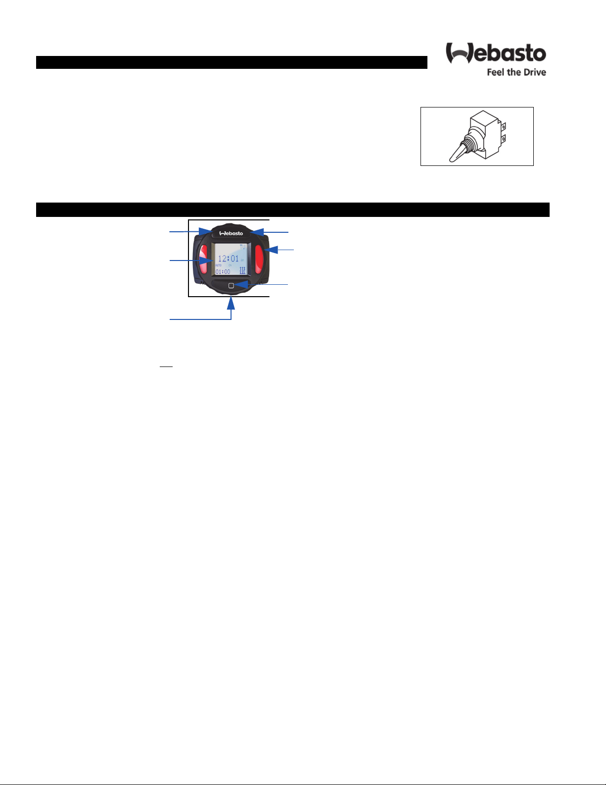
Control Element
Using the Switch
Switching ON:
When the switch is used, the operation indicator (toggle) lights up. Shortly thereafter, the
heater begins operation and delivers heated coolant to the engine or heat exchanger.
Switching OFF:
When heating is no longer required, switch the toggle switch OFF. The indicator light
A separate switch (optional) allows the user to choose between heating and ventilation mode. In ventilation mode the fan
turns off, combustion extinguishes, followed by an after-run cycle.
speed depends on the position of the control element knob.
SmarTemp Control
ON/OFF Button
LCD Screen
*Micro USB
Service Port
* The micro USB service port is not used for heater diagnostic purposes on
SmarTemp Control fc 2.0
Rotary Knob
a
Screw Cap
Selection Button
Page 4
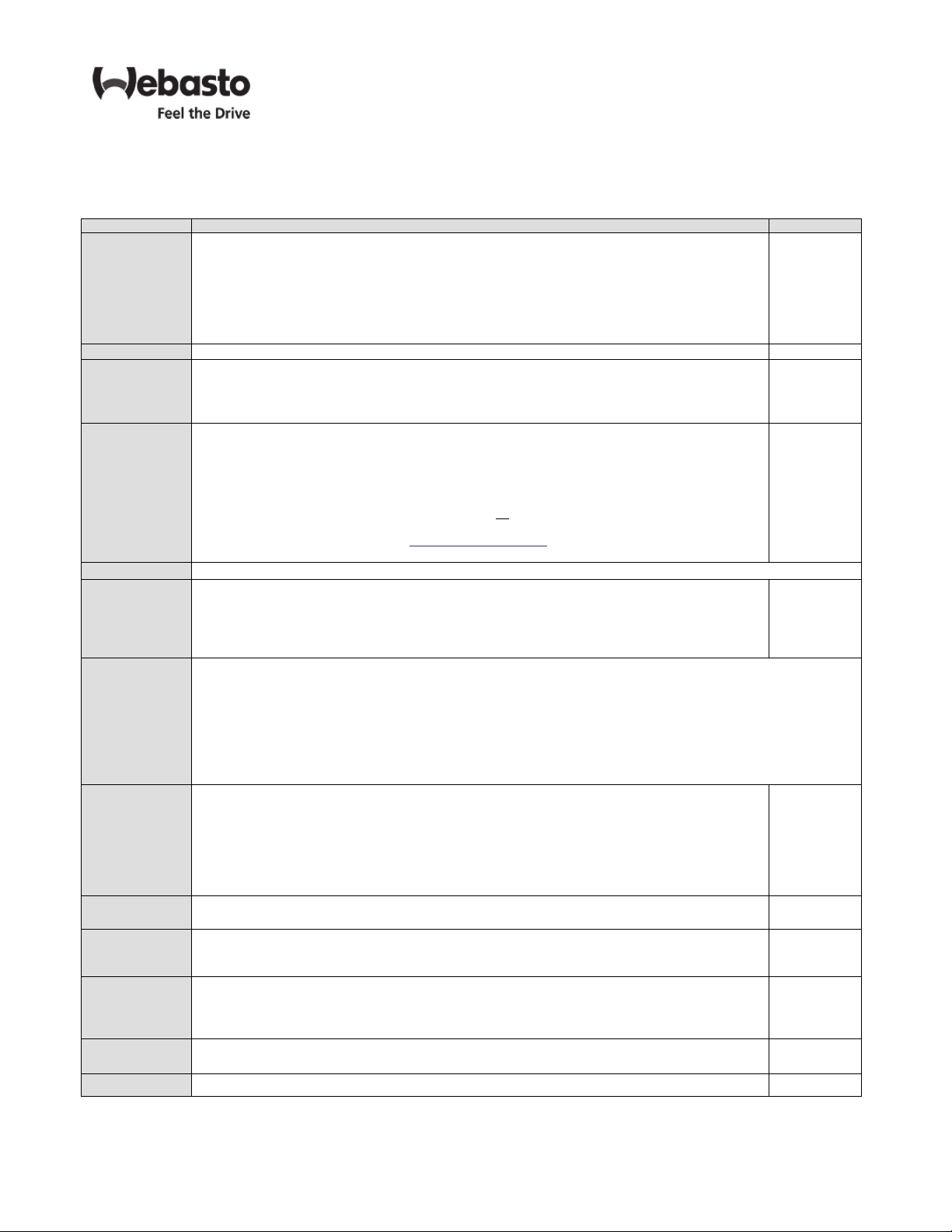
Menu Description
Refer to Menu Descriptions Table for a detailed description of each menu item and its default setting. Depending on
the SmarTemp version, menu order may vary from below.
aXXX
Definitions Default
Two modes are possible:
- Auto mode enables the pre-defined timer programs. Manual ON/OFF functionality is still possible
while in this mode.
Mode
Language
Duration
Error Code
Options Advanced level adjustments; see below
Time and Date
Timer
LVD
Default
Password
Hour Meter
SW Version
Back Select this to return to the previous screen
- Manual Mode allows the heater to be operated via the Webasto button on the SmarTemp
Control fx 2.0. While in Manual Mode, all Auto Mode functionality is permanently disabled.
Note: While in manual mode the heater will continue to operate based on the pre-defined
“Duration” set by the user. See “Duration” for further detail.
Language changes between English, Spanish, and French.
Duration allows user to select the heater runtime of the heater. Set range is between 10 – 120
minutes selectable by 10 minute increments.
Note: Duration time for all timers will default to the set duration time. User will have the ability to
manually change duration for each timer.
This section will log the last 5 error codes and the date that it was set. Highlight and select an error
code for a full description.
If the heater produces an error code, the status indicator lights will flash red and the error will
display on the main screen. Error codes cannot be reset through the Webasto SmarTemp Control fx
2.0 on the heater, a Webasto PC Diagnostics tool is needed. Refer to the heater service manual for
resetting an error code.
Note: Diagnostics via blink code is not available on
with no blink code functionality can still be obtained using the PC Diagnostics test tool. Refer to the
applicable service manual by visiting www.techwebasto.com for detailed PC diagnostics
information.
Time & Date allows user to properly set the current date and time. User also has the ability to
switch between AM/PM and 24 hour format. If the 24 hour format is selected the date format will
change to dd/mm/yyyy. Use the rotary knob to choose the time / date and the selection button to
confirm each entry. The Webasto button can be used to go back to the previous field if additional
changes are needed.
There are 4 heater start-up cycles possible 7 days per week. The timer is separated into to three categories. The user
can select “Mon-Fri”, set each specific timer (T1 – T4) for a typical work week all at once. A weekend “Sat-Sun”
can be scheduled in the same manner or a full week by using the “Mon-Sun” selection. The “custom” link allows
the user to set a specific timer (T1 – T4) for each individual day.
When selecting a specific timer a sub-menu will appear (Edit, Skip, and Off). To change the timer cycle, select
“edit”. Changes are saved immediately. The “skip” feature allows a timer cycle to be skipped one time within a 7
day period. Timer will reactivate after this one-time skip cycle.
Note: To turn a specific timer off permanently select “off”.
LVD “Low Voltage Disconnect” allows the user to adjust the battery voltage level at which the
Webasto SmarTemp Control fx 2.0 will shut the heater off. A warning (LED and message) will
appear after 8 minutes of low voltage. The warning will remain on for 2 minutes before the heater
is shut off.
If battery voltage is equal to or less than the threshold selected +0.1v, the heater will not start. i.e.
if an 11.5v threshold is selected the heater cannot be started until B+ has reached 11.7v.
12 volt - Range between 11v – 12.5v | 24 volt - Range between 21v – 25.5v
Default allows the user to perform a reset to all default values.
Note: A power loss will not reset user programmed values.
A password can be set to prevent access to the advanced “Options” menu. Enter a 4 digit passcode to begin securing the “Options” menu.
Note: This is typically used in fleet vehicle applications.
The hour meter logs the operating hours of an active ON signal to the heater. This does not reflect
the true runtime of the heater itself.
Note: For warranty purposes a diagnostic printout is still required where applicable. This hour
meter is for reference only
This displays the firmware version of the Webasto SmarTemp Control fx 2.0. Installed
all coolant heaters. Error Codes on products
Manual
English
60 minutes
No Errors
AM/PM
mm/dd/yyyy
11.4v
24.2v
N/A
OFF
N/A
Version
IMPORTANT - The Red status indicators (heater "ON") and LCD screen backlight turn off after 30 seconds. A touch
of any button or a turn of the rotary knob will re-activate these lights. If the "Webasto" button is used to re-activate
these lights, an additional press of this button is necessary to turn the heater off. Note that when the heater is "ON"
the display is active.
Page 5

Programming the 24 Hour Digital Timer with 3 Time Settings
Operation.
Operation of the timer is designed so that the symbols flash rapidly in the setting mode. If no
button is pressed within 5 seconds, the displayed time will be saved.
The display changes at high speed when the and buttons are pressed for more than 2
seconds.
Whenever the power supply to the timer is disconnected, all previously programmed settings
will be lost.
Switching On.
Manually: by pressing the “Manual Operation” button (continuous heating mode).
The heating time and the symbol for heating operation are displayed.
The heating time display disappears after 10 seconds.
Automatically:
upon reaching the preset starting time for heating.
The program number and the symbol for heating are displayed.
Switching Off.
Manually: by pressing the “Manual Operation” button.
Automatically:
via the programmed end time.
The display field goes out when the heating time expires.
Setting the Time.
This function is not available when heating mode is active!
Press and hold the button. Press the “Forward” or “Reverse” button as well.
The time of the day is displayed and the clock symbol flashes.
Set the time via the “Forward” or “Reverse” buttons.
The set time is saved when the display goes out or by pressing the button.
Viewing the Time.
Press the “Forward” or “Reverse” button.
NOTE:
The remaining operating time is displayed if heating mode is active.
Forward
(viewing
the time)
Reverse
(viewing
the time)
Ventilation Mode Indicator
Heater Operation Indicator
Program
Selection
Program Number Indicator
Manual Operation
Symbol for
Setting / Viewing
the Time
Time / Remaining Time
*
*ventilation mode not
available on BlueHeat
Page 6

Programming the 24 Hour Digital Timer with 3 Time Settings
Continued:
Program Start of Heating.
Press the button. Press the “Forward” or “Reverse” buttons within 10 seconds until
the required time for starting heating operation is displayed.
If a different program number is required, the button must be pressed within 10 seconds.
Default start settings:
Time 1: 06:00 hours or 6:00 am
Time 2: 16:00 hours or 4:00 pm
Time 3: 22:00 hours or 10:00 pm
NOTE:
The default settings are overwritten when new values are entered. The preset times are
saved until changed. The default settings are restored when the timer is disconnected from
the on-board power supply.
Deactivate Preset Time.
Briefly press the button.
Select Preset Time.
Press the button within 10 seconds until the program number with the required preset time
is displayed. The active mode (heating ) and the program number flash.
Set Heating Duration Time.
Press and hold the button. Press the “Forward” or “Reverse” button as well.
Release both buttons. The time and clock symbol are displayed.
Press and hold the button again. Press the “Forward” or “Reverse” button as well.
Release both buttons. The preset time is displayed and the heating symbol and ventilation
symbol flash. Set the heating time via the “Forward” or “Reverse” buttons. The set
heating time is saved when the display goes out or by pressing the button.
NOTE:
The default settings are restored when the timer is disconnected from the on-board power
supply. In this case, the timer will revert to the default heating duration time setting of 30
minutes.
Set Remaining Time.
The active remaining time can be changed between 10 minutes and 60 minutes via the
“Forward” or “Reverse” buttons when heating mode is active.
*
*Changing the Operating Mode.
NOTE:
Ventilation mode is not available on the BlueHeat heater. The ventilation mode is only
available with certain heater versions. This information is provided in the event mode of
operation is inadvertently changed.
Press the button. Press the button again and hold it.
The last mode (heating or ventilation ) is displayed. Press the “Forward” or “Reverse”
button as well to change back and forth between heating or ventilation mode.
Page 7

MultiControl Element and Menu Structure
NOTE: For more detailed information on the operation of the MultiControl control panel, refer to the operation guide
located at www.techwebasto.com
1 Menu name 2 Menu symbol
3 Activated time settings, altitude correction* 4 Time
5 Quick-start button with status display 6 Control knob
* - Optional
Button Control and Function
Quick-start button with status display
Turn the control knob (turn/push button) to select a function.
Press the control knob (turn/push button) for confirmation of the selected function.
Page 8

Status LED Backlight Color and State
Heating mode GREEN ON
Ventilation mode BLUE ON
Switched off heater - control element is activated WHITE ON
Error - no heating mode RED FLASHING
Preprogrammed heating mode - control element in stand-by mode GREEN FLASHING
Preprogrammed ventilation mode - control element in stand-by
mode
NOTE: If a user does not make any inputs with the control unit within 60 seconds and the heater is switched off, the
control uni will go into stand-by mode (display and LED are switched off).
BLUE FLASHING
Switching the heater ON using the quick-start button
The Quick Start button enables heating or ventilation with the push of one button . The operating mode can be
adjusted to your personal preferences. Refer to the MultiControl operation manual on www.techwebasto.com.
Heating: Quick start button is programmed for heating
Heater starts. The display screen shows the symbol
for “Heating” as well as the run-time remaining.
The quick start button shows a green light.
Ventilation: Quick start button is programmed for ventilation
Ventilation fan turns on. The fan speed and operating time are shown on the display. The quick
start button shows a blue light.
*Not available in
North America
Error Messages
Error messages regarding the heater will be displayed with the “F” or “H” designation displayed before the numerical
error code. Explanations of these error codes can be found in the appropriate heater service manual. Error messages
regarding the control element are displayed by means of “T” symbol. These error codes can be found in the operation
manual for the MultiControl.
Error Codes
If error messages appear on the display, please contact Webasto technical support at 800-860-7866.
Page 9

Fault Codes
NOTE: Not all Webasto coolant heaters show fault codes.
Fault
Code
F00
or
0*
F01
or
1*
F02
or
2*
F03
or
3*
F04
or
4*
F05
or
5*
F06
or
6*
F07
or
7*
F08
or
8*
Error
Message
No error
Heater Lock-
1
out
No start
Flame failure/
Flame abort
Supply Voltage Too High/
Low
Premature
flame detection
Flame sensor
defective
2
Temperature
sensor openor short-circuit
Metering/Fuel
pump defective
Fuel solenoid
defective
2
Combustion
air fan defective/blocked
Possible Cause
• Fuses
• Electrical wiring
• Heater lock-out
• Control Unit Defective
• Fuel system
• Combustion air/exhaust pipe
• Burner unit
• Fuel system
• Burner unit
• Power supply
• Foreign light detected during
run-up or run-down
2
• Flame sensor defective
• Exhaust temperature sensor
defective
1
• Defective Flame sensor • Check flame sensor
• Wiring
• Coolant temperature sensor
defective
• Wiring
• Defective pump
• Wiring
• Blockage
• Defective fan
Recommended
Action
• Check fuses
• Check control
element
• Check W-bus connections (yellow
• Check fuel level
• Check fuel filter
• Check fuel extractor and fuel line for
leaks
• Bleed fuel system
• Check combustion air/exhaust pipe
• Check fuel level
• Check fuel filter
• Check fuel extractor and fuel lines for
leaks
• Bleed fuel system
• Clean/replace burner
• Check battery
• Check electrical connections
• Check flame monitor
• Check exhaust gas temperature sen-
1
sor
• Check wiring/sensor for resistance
• Check operation of sensor
• Check wiring for damage
• Check fuel pump for operation
• Check wiring for damage
• Remove blockage
• Replace fan
Applicable Heaters
Thermo Pro 50 ECO
Thermo Pro 90
Thermo 230/300/
350
Thermo 50
Thermo Pro 50 ECO
Thermo 90 ST
Thermo Pro 90
Thermo 230/300/
350
Thermo 50
Thermo Pro 50 ECO
Thermo 90 ST
Thermo Pro 90
Thermo 230/300/
350
Thermo 50
Thermo Pro 50 ECO
Thermo 90 ST
Thermo Pro 90
Thermo 230/300/
350
Thermo 50
Thermo Pro 50 ECO
Thermo 90 ST
Thermo Pro 90
Thermo 230/300/
350
Thermo 50
Thermo 90 ST
Thermo 230/300/
350
Thermo 50
Thermo Pro 50 ECO
Thermo 90 ST
Thermo Pro 90
Thermo 230/300/
350
Thermo 50
Thermo Pro 50 ECO
Thermo 90 ST
Thermo Pro 90
Thermo 230/300/
350
Thermo 50
Thermo Pro 50 ECO
Thermo 90 ST
Thermo Pro 90
Page 10

F09
9*
or
pump defec-
2
tive
Glow plug de-
• Defective pump or wiring
2
• Defective glow plug or wiring
• Check pump operation and wiring
• Check glow plug operation and wiring
fective
Circulation
• Replace temperature limiter
• Check coolant level/bleed coolant
• Check coolant pump operation
• Check temperature protection wiring
• Check operation of overheat protection, replace as necessary
• Replace igniter box/electrodes
• Repair wiring
• Replace pump
• Repair cause of malfunction
• Check wiring for damage
• Check battery disconnector
• Check wiring for damage
• Check vehicle fan relay operation
• Check wiring for damage
• Check overheat protection for proper
operation
• Check wiring for damage
• Check operation of glow plug
F10 or
10*
F11
or
11*
F12
or
12*
F13
or
13*
F14
or
14*
F15
or
15*
Temperature
limiter defective/overheat-
2
ing
Overheating
Igniter box
defective
2
Circulation
pump defective
Heater lock-
2
out
Operation of
vehicle fan
defective
Vehicle fan
short circuit
Overheat sensor short circuit
Glow or
ignition element circuit
defective
• Temperature limiter defective
2
• Heater overheating
• Overheat protection defective
• Defective igniter box/elec-
2
trodes
• Pump wiring
• Defective pump
• Repeated malfunction or
flame-out
2
• Main battery switch defective
• Wiring
• Vehicle fan relay defective
• Wiring
• Overheating protection sensor defective
• Wiring
• Glow plug defective
• Check wiring
F16
or
16*
Exhaust gas
temperature
high
• Exhaust gas temperature sensor defective
• Heater fouled
• Check operation of exhaust gas temperature sensor
• Check burner and heat exchanger for
fouling
or
Exhaust gas
temperature
sensor open
or short circuit
• Wiring
• Exhaust gas temperature sensor defective
• Check wiring for damage
• Check operation of exhaust gas temperature sensor, replace if necessary
F17
17*
* - Indicator lamp of control element flashing: number of long flashes after 5 rapid flashes
** - Were applicable
1 - Thermo Pro 50 ECO
2 - Thermo 230/300/350
Thermo 230/300/
350
Thermo 50
Thermo Pro 50 ECO
Thermo 90 ST
Thermo Pro 90
Thermo 230/300/
350
Thermo 50
Thermo Pro 50 ECO
Thermo 90 ST
Thermo Pro 90
Thermo 230/300/
350
Thermo 50
Thermo Pro 50 ECO
Thermo 90 ST
Thermo Pro 90
2
Thermo 230/300/
350
Thermo Pro 50 ECO
Thermo Pro 90
Thermo Pro 50 ECO
Thermo Pro 90
Thermo Pro 50 ECO
Thermo Pro 90
Thermo Pro 50 ECO
Thermo Pro 90
Thermo Pro 50 ECO
Thermo Pro 90
Thermo Pro 50 ECO
Thermo Pro 90
Page 11

Limited Non-Transferable Warranty
If an error occurs, first check the fuse and plug connections to ensure that they are in proper condition and connected
correctly.
If the actions described below do not rectify the error, have the heater checked by Webasto-trained personnel.
Heater unit cuts out automatically
Cause Remedy
No combustion after
start and repeat start
Flame extinguishes during
operation
Heater unit overheats and indicator flash-esMake sure that water/coolant can flow freely, allow heater
Switch heater unit off (for at least 2 seconds) and then on
again
Switch heater unit off (for at least 2 seconds) and then on
again
unit to cool down, Switch heater unit off (for at least 2 seconds) and then turn on again
Vehicle voltage too low Charge battery
Heater unit emits black smoke
Cause Remedy
Combustion air and/or exhaust system
blocked
Webasto Thermo & Comfort North America, Inc. (hereinafter referred to as Webasto)
warrants their heaters and heater kits against defects in material and workmanship for two (2) years effective at the time of installation or vehicle registration date for original equipment installation (OEM). This warranty period may not exceed three (3) years from
the original date of sale by Webasto. This warranty period may be superseded by written contractual agreements.
All models are limited to 2,000 maximum operating hours.
Replacement parts are covered for six (6) months or the remainder of the original warranty period, whichever is longer.
The intent of the Webasto warranty is to protect the original end-user of the heater from defects and provide free repair and replacement of defective parts in the manner provided herein. During the warranty period, the exclusive remedy will be for Webasto,
at their discretion, to repair or replace those parts which are demonstrated to be defective in material or workmanship.
While warranty is provided to the “original end-user”, it is to be administered and serviced through an authorized Webasto dealer
in accordance with the Webasto warranty policy or contractual agreement between Webasto and a second party.
To locate the nearest Webasto authorized dealer for warranty service:
visit http://www.techwebasto.com or call (800) 860-7866 in USA, (800) 667-8900 in Canada.
Switch heater unit off (for at least 2 seconds) and then turn on
again
Check combustion air and exhaust system for blockage
The heater can be registered by visiting www.techwebasto.com or by
scanning the code.
A proof of purchase is required for all heaters that are not registered.
Page 12

Org. 10/2017 Rev. 07/2019 P/N: 5012725A
Webasto Thermo & Comfort N.A., Inc
15083 North Road
Fenton, MI 48430
Technical Assistance Hotline
USA: (800) 860-7866
Canada: (800) 667-8900
www.webasto.us
www.techwebasto.com
 Loading...