


TYRE
CHANGER
READ THIS ENTIRE
BEFORE
RECORD HERE
THE
ON
OPERATION BEGINS
THE FOLLOWING INFORMATION
WHICH IS LOCATED
SERIAL NUMBER DATA
Serial
No.
MANUAL
PLATE
Model No.
Manufacturing
date.

INDEX
lmportantsafety
Preface-Information
Brief
Technical
Structure
Warning
Installation
fnstallation
Maintenance
Introduction
data
stickers
forsemi-automatic
forcompletely
instructions
and instruction
of
the machine
machine-
automatic
machine
-
-
-----
------1
-----
----
---
---2
---
- -
-
---
1
1
1
2
3
3
4
4
Instructions
Demounting
Mounting
fnflating
Inflate
Transport
Electrical
AdjustmentfordualAdjustment
tires
forthe
with
diagram
for
lT
system
the completely
operation
locking
machine
automatic
machine
-----
-----
---6
----
- -
---7
---7
-----
- -
5
5
z
7
8
g
IMPORTANT
Read these safety instructions entirely!
FETY'NSTR UCT'ONS
SA
Read and understand all
Preface
Thanks for choosing
and motorcycle
prolonging
and
this tire changer. This machine
with the
the
principle
work life of the machine,
lnfo.1mati91
Information about tire changer,
parts
technical service
For
difference between the data
Carefully keep this manual
n ient u nderstand ing, th is manual contains
conve
and
safety
is
designed and
quality
of best
please
such as type, specifications and
replacement.
in this manual and that on the
for use at any time.
highest working efficiency, For ensuring correct and
and
read this
the relevant information about the
instructions
manual carefully.
related data, are helpful for service
nameplate, take the data on nameplate as correct
before
made
specially
operating
for changing the
machine
tires of
automobile
safe operation,
technician to
machine. Should there beany
one.
provide
Introduction
Brief
'
.r-
: r "'
Scope of Application
This tire changer is specially designed
Nofe; This machine can only be
purpose.
Any damage caused by
Safety Regulations
Only the trained and
nonobservance of instruction may cause
:*!- r
:i::.'
qualified
used for the
incorrect use
operators can be allowed to operate
for removing tire from rim and installing
purpose
will not be covered under
machine damage.
designed
warranty.
manufacturer.
by the
the machine. Unauthorized
tire onto rim.
Do not use
it for any other
change of
parts
or
1-
1 Technical
Data
Applicable
Max.wheel
Max.wheel
Outside locking(RlM):(10
lnside
Range
width:330mm
diameter:920mm
locking(RlM)'.
(12"
"
-19''
-21''
motor
Power
supply:1
Electric
Weight
Net
weight:185k9
Air
device
Operating
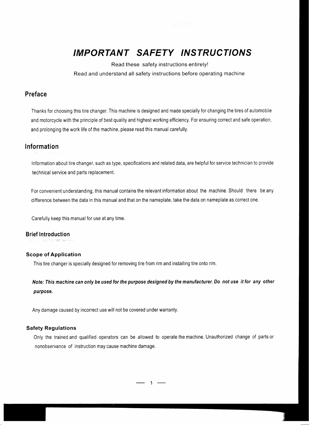
Operation
1
. Single-
2,
Mount/demount
3. Bead
4. Front
5.
Gun inflator
6. Turntable
7
,
Cylinder
8. Turntable
L
Clamp
10.
Tire
11.
Bead
1 0V I 220V
motor:
1
,1kw/0.75kw
pressure:
parts
of semi-automatic,
locking
lifting
tool
logo
control
control
control
breaker
pedal
pedal
shoe
8-1 0bar
handle
head
pedal
1380V
(clockwise
(10
)
(2tr
)
50/60H2
single-
or counter
"
-29'r
-23'r
locking
machine(Fig.1)
clockwise)
"
"C
,tt
r
'
..'t r
t's$
4:a.,
-
-L'-
\t
''l
-
t
'l
'i)
-29''
"
-22''
1
1
Moving
Moving
RPM
Phase:
working
working
grip
inside(RlM):8
grip
outside(RlM):10
of turntable:7rpm
Single/Three
conditions
temperature,0-45
.-S*
s.
'
i0
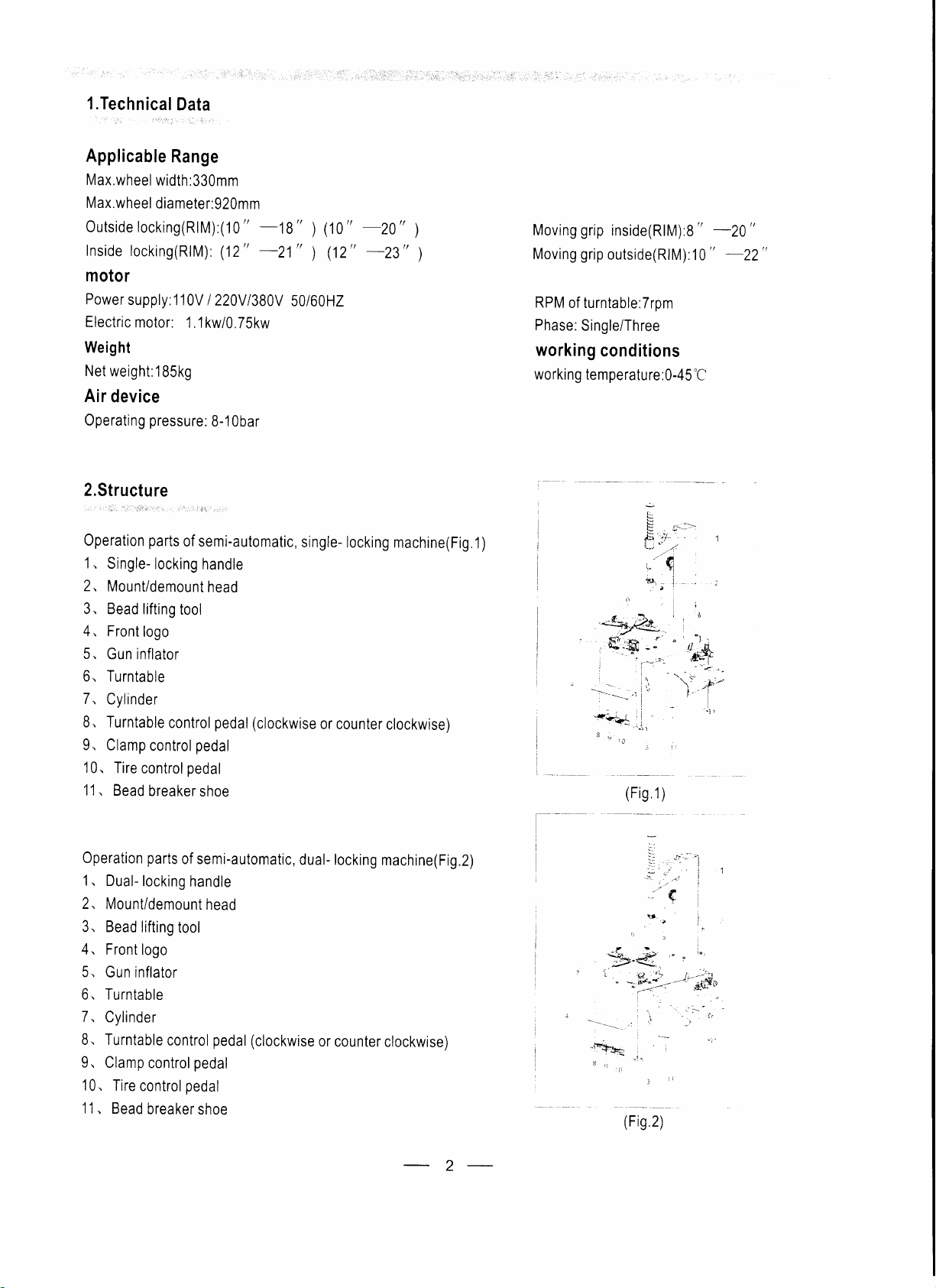
Operation
1 . Dual-
2, Mount/demount
3. Bead
4. Front
5.
parts
of semi-automatic,
locking
lifting
tool
logo
Gun inflator
handle
head
6. Turntable
7.
Cylinder
8. Turntable
9.
Clamp
10.
Tire
'11
. Bead
control
control
control
breaker
pedal
pedal
pedal
shoe
dual- locking
(clockwise
or
machine(Fig.2)
counter
clockwise)
a:
!r-
::
l
:,:,,. - |
.:1
!
..
-{E+*
s-
:
*
L'
iq-,*i
"z\-"
i?.'.= l-.-':t
"
*;ilt-4-.-
.;
\:+f
.
-ir
/trin ?\
ry.4_/
\r
.,:-
-t*
{t-
"'
.
\
t,
3
'f
i
-
r,
:
-'*,f$n
-.
i
I
!
..
,
''
2

Operation
'1
. Pedal for
2 Pedal for
Pedal
3.
4 Tool
Pedal
5.
Tire
6.
7.
Clamping
8. Jaw
Mount/demount
9.
10 Vertical
11
12.
13 Air
14.
1
5.
16. Rubber
Warning
A
A
A
A
A
n
/t\
l_f
parts
for completely
tilting
rotating the
pressing
for
box
for
expanding the
crowbar
chuck
shaft
Lock lever
Horizontal
pressure
Air valve
Bead
arm
gauge
breaker
oad
stickers and
place
Never
and cause injury
Never
olace
operator.
place
Never
operator
jaws
The
operat0r,
The
operator shouid wear the
avoid
something blow
put
Never
should
mounting
the
clamping
the tire
jaws
head
shoe
instruction
leg
between the bead
of the operator.
hand
on the tire when the demount head
your
hand
in
closed
hand
between the
automatic machine
column
chuck
of the
between the tire and
position
protection
into
eyes.
rim
and tire when inflate the tire,
machine
breaker shoe and
not in
but
glasses
(Fig.3)
gripping
position
open
when inflate
bead
breaker
is
on the working
device
when
rubber,
when
operate
do the bead break,
the tires with the machine with
avoid the
I
I
--i-
,,\
-1
(Fis
3)
avoid stepping the wrong
position,
the rim,
injury
avoid the injury of the
injury
the injury
GT system,
of
the
avoid the
avoid
operator.
pedal
of the
the
of
There
A
/.\
Installation
SPACE REQUIRED
When
choose the
sure that it
The
semi-automatic tire
connected
and air compressed
advisable
place
The
operated
lf
the machine is
should be nobody
for
semi-automatic machine
place
complies with
to the main
system.
install
to
of
correctly and without any restriction.
the
installation
installed outside, it must
behind the tilting
for installation
current safety regulations.
changer must
lt is
must
power
provide
electric
machine near
be
be
supply
therefore
power
these
at least the space shown in figure 4,
protected
be
pole,
when
(Fig.4)
sources.
bv a
the machine is
lean-to.
3
the working
on
so as to allow all
position
(
)
Fig,a
parts
of the machine to be

) The
tire changer
with
electric motor
can't
be used in
explosive
atmospheres,
unless if is
proper
a
version.
Installation for
Place
the machine
into the hole
caponthetop
tilting arm, then
part
of
the
side of the machine.
During
(Fig.5).(
of
tighten the bolt. Take
B,
then insert
After the
above operation is
the operation,
the completely
on the chosen
Do
not bend the hose) Then
partA,insertthepartAintotheholethat
part
B into the hole that
Connect the PU hose
pay
attention
automatic machine
place,
then fix it to the
take out the
part
out the
finished, mount
(shown
B
go
through the
(G)
that
the
to the PU hose and
ground
in
part
go
through
part
E on the
other
fixing
by
partA
go
through
Fig,5) from the
D, E,
the main box
arm
parts,
screw. Lift
(
shown in Fig.5) from
the tilting arm, and insert the PU
the accessory box,
the main box ofthemachineand
accessory box, unscrew the
then screw the spring. Dismount
the machine
of
(Fig.6),
then mount
B
C
parts
the
with the
D,
B,
C,
r.
tIP--T
part
r*
(G)
hose
unscrewthe
thebottomof the
spring on one side
protection
plate
on
F.
A, G, F in sequence.
)
lnsert
the expansion
may
cause noise
Maintenance
'.,-
'.
r,.
-,:.
-
The
followin
)
Only fhe
)
Before
*Check
source,
*Clean
*Check
*Keep
*Check
*Keep
the
then fill
and lubricate
all connecting
the hexagonal
and
the machine
*Lubricate
specialized
doing
oil level in
adjust
all the moving
(Fis.5)
bolt into
other
problems.
technician
and
maintenance
any maintenance,
the
air-compressed
the
SAE30
oil.
all the moving
parts
and bolts
vertical
the tension
and the
working
side of the machine
the hole
must
axle clean and lubricate
of the
at the
bottom
be done at least
can do
shut
cup
parts
of the turntable.
periodically
driving
area
clean to
of the machine
maintenance.
the
power
off
periodically.
and tighten
(Fig.9)
belt.
avoid the
once eve month.
weekly.
fix
to
supplv
lf it
periodically.
it
and
needs
(Fig.7)
them if necessary.
dust entering
(Fig,6)
the machine,
air source.
to be filled,
(Fig
8)
the moving
or if it is not
you
must
parts.
steady, it
shut off
(Fig.7)
air
4

*Prepare
go
through the
a water segregator
machine.
near the
Instructions for the operation
air-compressor,
(Fis,8)
to reduce the
amount of the
water
the air that
Only the trained
)
person
can do the operation of the
Demounting
l.Release
2.Remove the balance block
Do
l,Place the tire between the bead breaker shoe and
the
(Fis.11)
) Lubricate
operation.
2,Repeat above steps on the other
3.Set
mount/demount head should be 2
lock
all the air
the operation as
tire control
vertical
the
(automatic
inside
follow:
pedal
(10), (in
the bead
in the
shaft
machine
the tire,
from
the external side of
Fig2
step
with thick soap solution before demounting the tire, avoid
parts
working
mm
locking handle 11 to lockthe Fig.3)
use
pedal
the
of the tire
position,
so that the
from the
10, and
to
rim
machine.
the rim.
rubber
get
to
(Fig.10)
pad,
in Fig3
the tire separated
mount/demount head is near the
prevent
make the
and
step the
scratching
pedal
thoroughly
the
shoe between
rim.
the bead and
to
3)
separate
the damage and
from the rim.
rim. The roller in the
(Fig.12)Turn
the tire,
the bead
the lock lever to
from the rim.
facilitating the
(Fig.10)
step on
+
The
iJofe;
the angle of the
user can
{i
(#
mounUdemount
re-calibrate it with hexangular
(Fig.1
1
)
head is
spanner
already calibrated
for
the overlarge or
5
according to the standard
over small rim so as nof to damage the tire.
rim
before delivery.
(Fis.12)

4.Liftthe
step
(Fig.13),
tube, so
)
in FigJ
bead
ontothe mount/demounthead
pedal
the
on
it is
as not to
lf
the denounting is blocked,
pull
8
and
suggested to
damage the tube
up the
pedal
in Fig
3 step on the
place
the mount/demount
stop the machine at once,
2)
to turn the turntable
with
the
pedal
2) to
lifting
bead
turn the
head
about 10mm
tool,
and stepon
turntable clockwise
to the right
pull
and
up the
counter-crockwise, so as fo clear
theturntable control
till the bead is
side of the air
pedal
I
(in
completely separated
valve
pull
Fig 2
up the block.
pedal
if the wheel has
up the
(in
Fig
B
pedat
I and
2
a
5.Takeoutthetubeif
above
steps to demount the
your
Keep
)
bracelet ot loose
thereis.Turnover
hand and body away ftom
blouse for the operctors.
Mounting (Fig15)
the wheel tolet
other
side of the bead.
(Fis
13)
(Fig.1a)
the moving
the
othersidetowardthemount/demounthead.andreoeat
(Fis
1a)
parts
du ng
the operation, lt is very dangercus
to
wear necklace,
the
)
Make
sure that
'1
Clamo the rim
2.Lubricate the
3.Put the bead
simultaneously, and turn the
4.Cover
horizontal
the
tube onto the rim if
side of the tire,
)
It is nof
swing arm.
)
Do not
the size
on the turntable.
with
bead
on the
soao solution.
machine
necessary
put
your
hand
rim
of the
with
turntable
there is, and repeat
move
to
and tire is same
left
the
side upward,
clockwise to let the
the locking handle
between the
before mounti
and
oress down the tire
bead enter the
the above
steps
every time, if
tire and swing arm during locking,
6
bead seat
to mount
the
the size
upper
of the
so as to
\
rims is
fhe same,
avoid body
(Fis
15)
just
injury,
move
the

Inflating
(Fig16)
This machine is
1 .Loose the tire from the turntable.
2. Connect the inflator with
3.Press the
Inflate
l.There is
tube.
not exceed the manufacturer's limit.
2.The
and
gauge
tires with lT system
Step
second
then make
doesn't exceed the manufacturer's limit.
gun
pedal
a
pedal
the
position
the
equipped
inflator
slowly
on the
side of the
lightly for
is for
pedal
to the first
with
a
the air
for
several
inflation
the
gauge
valve
several
machine.
(Fig.17)
position
pressure
for
on the tire.
times. Make
This
times
during the inflation, Make sure the reading on the
for the tubeless tire, step the
to continue the inflation.
reading
pedal
during
sure the reading on the
has two
positions.
inflation.
The first
pedal
down fully to the
Make
sure
that the reading
(Fig
gauge
does not exceed the manufacturer's limrt
position
is for the inflation for the tire with
gauge
does
bottom,
on
16)
your
Keep
)
not
damaged
hand
before the inflation, and
Transport
Make
sure transportthe
package.
on the
capacity,
Electrical
)Make
)The
)
Make
electric caoacitot.
The
insertthe
diagram
surc the machine is connected with
operation of the elecfiicity must
surc the steady of the extemal
and body
machine with its original
packed
machine should be moved
forks
at the
from
away
points
shown in
fhe
in
re
the fire
by means
ground
the
parts
during
the operation, avoid the
not
does
place
and
it
according
fork lift truck of suitable
of a
beforc the opention.
exceed 3.5 bar.
to the marks
the moving
pressu
package,
(Fig.18).
be done by the autho zed opentors.
power
supply,
if
the rated
power
is 220v, so as to avoid the damage of the
injury.
,?
t Fig.'1 7
Make sure
(Fig
18)
)
the fire
is
i
7

phasC
t.
ruotirr
:\C22()\ l.l li\\ I l()()rirnr
St:rrting
t apacitor 1;r()trl:i,\C2;l()\.
('lrpat'itor
lttrntting
25Lrlri,.\('?r()\
Adjustment
for
:
)
The
machines have
lf
the horizontal
Irlectrical
Electrical
dual-locking
machine
been
calibrated before
arm does not lock
diagrant frtr tire changer u'ith
diagram for the
motor rvith
single
(Fig.19)
delivery
well,
do the adjustment as following
by trained operator,
threer
1J 00rprr
phase
phase
porrer
and single.
steps.
s!'stent
capae irt,r'
so don' t adjust it
random.
at
8

The adjustment for the hexangular vertical shaft
Adjust the nut
(14)
and
(15)
lightly
until
it lock well.
(Fis.1
e)
The adjustment for
*Turn
*Turn
*Push
shaft
-Tighten
-lf
the nuts
handle
the
the swing arm to the
fixed
the
(1),
it
still does
shaft
then tighten the nut
the screw
not lock well
(11), (9),
The adjustment for
Do
the adjustment as
Shut off the
screw
Do the adjustment as follow
Remove the
can move smoothly, then
the change, till
pneumatic
in front
of the
cover on the tilt column, adjust the screw MG on two sides by spanner, meanwhile
it
fixing
the
(13)
(2)
the fixed shaft
position
to the
outside
(1)
by hand to make it
(5).
fully,
and
afterthe above steps, loose the nuts
the completely automatic
follow
supply, demount the vertical
plate,
then
tighten the
can only move in the range of 2mm, then lock the nut.
shaft of
turn
horizontal
shown as the figure, make the cross adapter
fully,
then loose the nut
slide
one circle back, then tighten the
(1)
will lock well.
arm
(3),
freely, then rotate the
loose the
and
nut
(11), (9),
screw
(3).
then rotate the bolt
screw
(4)
machine
steps, if the vertical shaft does not lock well.
connect
if
steps,
nut
shaft cover,
pneumatic
the
horizontal
the
and adjust the screw
supply and observe the
arm does
then
not move
in
the middle
the nut near the thread rod
adjust
smoothly, or
by spanner,
(8)
reach the fixed
(2)
about
out slowly, till
position.
locked
not lock well.
lock the horizontal
plate
(7).
20mm,
the
extreme
(10)
to make it short, then tighten
push
position
by spanner, or
the horizontal arm till it
arm and observe
of
fixed
lock the
) Read
fhe user's manual and teclmical data according to the type of the machine, The users will not be informed,
if this manual has some changes.
I
 Loading...