

Page 1

890IT-Series Wheel Clamp TIRE CHANGER
INSTRUCTION MANUAL
READ THIS ENTIRE MANUAL
BEFORE OPERATION BEGINS
Model 893-IT 20”turntable with internal clamping range 12"-23", external
clamping range 10"-20"
Model 898-IT 24”turntable internal clamping range 15"-28", external
clamping range 13"-24"
For servicing single piece automotive and most light truck tire/wheel assemblies
Safety Instructions
Operating Instructions
Installation Instructions
Maintenance Instructions
READ these instructions before placing unit in
service. KEEP these and other materials delivered
with the unit in a binder near the machine for
easeof reference bysupervisorsand operators.
Page 2

RECORD THE FOLLOWING INFORMATION WHICH IS LOCATED ON THE
SERIAL NUMBER DATA PLATE.
Serial Number: _________ Model:
Factory Code:
Technical Standard Code Q/YGM001--2006
This product has passed the examination.
Operators Protective Gear and Equipment
Personal protective equipment helps make tire changing safer. However, equipment does not take the place of
safe operating practices. Always wear durable work clothing during tire service activity. Shop aprons or shop
coats may also be worn, however loose fitting clothing should be avoided. Tight fitting leather gloves are
recommended to protect operator’s hands when handling worn tires and wheels. Sturdyleather work shoeswith
steel toes and oil resistant soles should be used by tire service personnel to help prevent injury in typical shop
activities.Eyeprotectionis essential duringtire service activity. Safety glasses with side shields, goggles,or
faceshields areacceptable.Back belts provide supportduringliftingactivitiesand are also helpful in providing
operator protection. Considerationshould alsobegiven to the use of hearing protection if tire service activity
is performed inanenclosedarea, orifnoiselevels are high.
WARNING
Failure to follow danger, warning, and caution instructions may lead to serious personal
injury or death to operator or bystanderor damage toproperty. Donot operate this machine
untilyoureadand understandallthedangers,warnings and cautions in this manual.
For additionaltire,wheel, and/orinflationinformationcontact the following:
RUBBER MANUFACTURERSASSOCIATION
1400 K Street N.W.
Washington, DC 20005
(202)682-4800www.rma.com
TIRE GUIDES, INC.
The Tire Information Center 1101-6 South Rogers Circle Boca Raton, FL 33487-2795
(561) 997-9229
www.tireguides.com
Page 3

Owner’s Responsibility
Tomaintainmachineandusersafety,the responsibility of the owner is to readand follow these
instructions:
Follow all installation instructions.
Make sure installation conforms to all applicable Local, State, and Federal Codes,Rules,
and Regulations; such as StateandFederalOSHARegulationsandElectrical Codes.
Carefully check the unit for correct initial function.
Readandfollow the safetyinstructions.Keepthemreadilyavailableformachineoperators.
Make certain all operators are properly trained,know howto safely andcorrectly operate the
unit, and are properly supervised.
Allow unit operationonly with all parts in place and operating safely.
Carefully inspect the unit on a regular basis and perform all maintenance as required.
Serviceandmaintaintheunitonlywithauthorized or approved replacement parts.
Keepallinstructionspermanentlywiththeunit andalldecalsonthe unit clean andvisible.
This tire changer comes with a very detailed and easy to understand instruction manual. This
manual assumes that the customer has used a wheel clamp style tire changer previously, or has
operators that have operated a wheel clamp style tire changer. If this is your first tire changer
purchase and you have not operated a wheel clamp style tire changer, it is strongly
recommended to have a person/trainer who is familiar with this style of tire changer train you in
the operation. This tire changer is very similar to many other tire changers on the market. The
distributor that sold this unit will be glad to give you a training session at their location or guide
you to someone who can provide a service call to your location for training (a service charge
would apply). The distributor also offers telephone technical support and trouble-shooting
suggestions as needed. This does not take away from the responsibility you have to read and
understand this complete manual.
This responsibility is no different than when you purchase an automobile. The automobile dealer
assumes you know how to operate and drive a motor vehicle. Safe operation is your
responsibility and the dealer assumes you know how. Seek training as needed.
DANGER
EXPLOSION HAZARD – NEVER EXCEED40 PSI WHILE SEATING
BEADS
Explosion Hazard Never inflate tire above manufacturer’s
recommended pressure after bead is seated.
Page 4
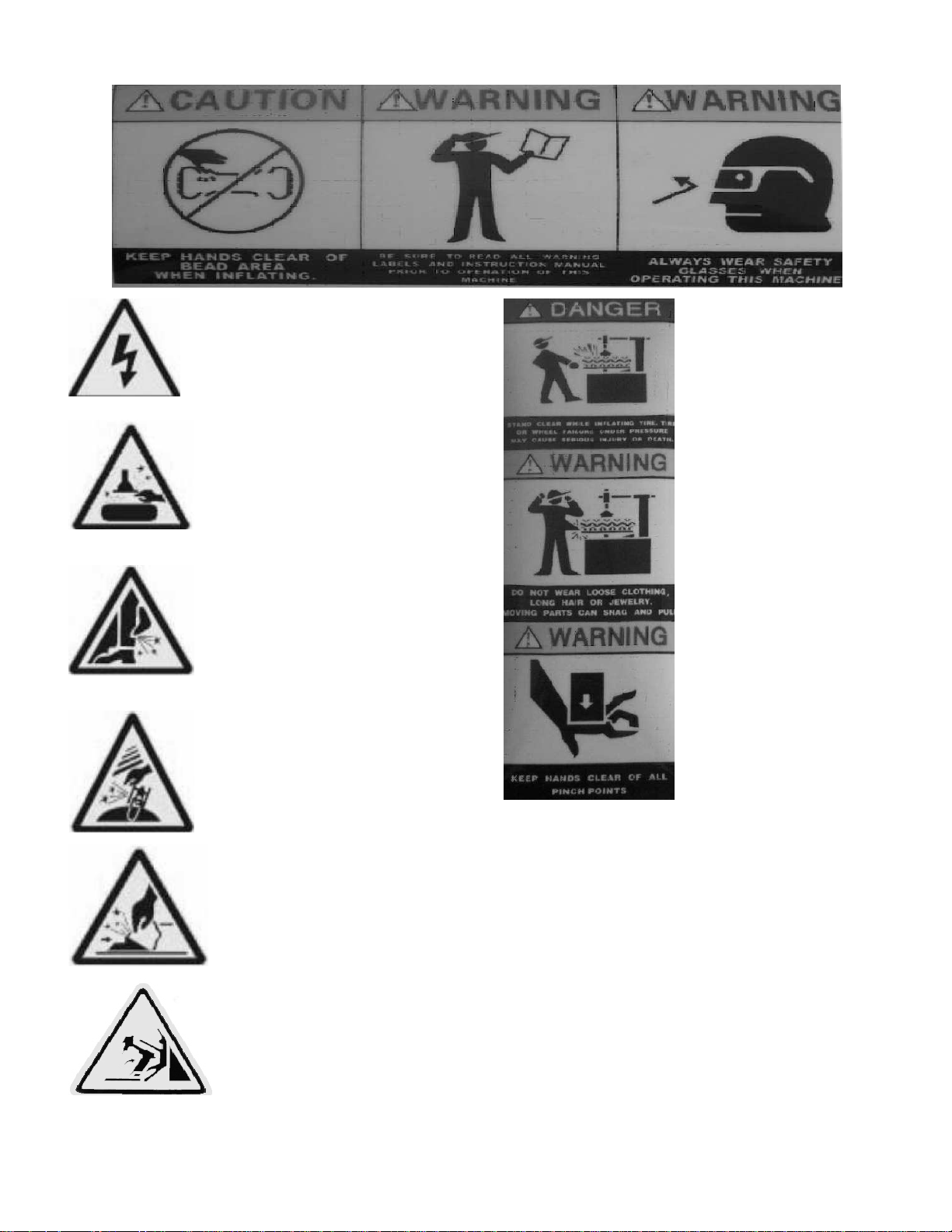
SAFTTY LABEL INSTRUCTION
.
Keep your hands far Carefully read operation When operation , wear
from tire when operation manual before operation the protective gear
electrical shock hazard!
Do not reach any part of your
body under the demount tool. When operating, do not
When rapid inflation,
ensure the wheel
clamped.
wear long hair, loose
clothing or jewelry
When breaking bead, the bead breaking
blade will quickly move leftwards. When operating, do not
SAFETY LABE Note: when pressing the tire, the
opened clamp cylinder may
injure the hand of the operator.
Remember, do not touch the side
wall of the tire.
When clamping the rim, do not
Reach your hand or other parts
Of the body in between the clamp
& the rim.
reach your hand under the
falling objects.
Do not stand behind the column to
Avoid injuring the persons when swinging arm
Page 5
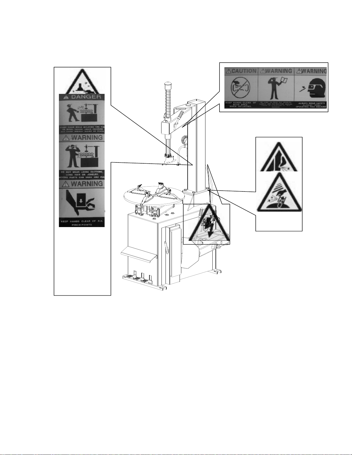
SAFETY LABEL POSITION DIAGRAM
Pay attention to keep the safety labels clean and readable at all times. Replace any label that is not clear, torn or
missing.
Operators review the safety labels clearly and understand the meaning of each label.
Page 6

CONTENT
CHAPTER Ⅰ BRIEF INTRODUCTION
1.1 BRIEF INTRODUCTION
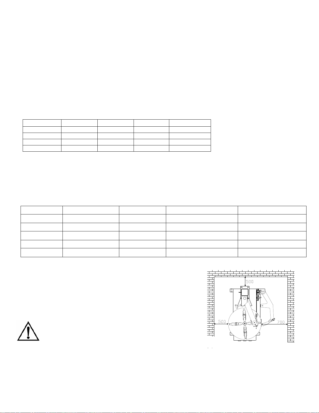
1.2 EQUIPMENT OVERALL DIMENSION (EXCLUDING THE ASSSISTANT)
1.3 TECHNICAL PARAMETER
1.4 APPLICATION SCOPE
1.5 ENVIRONMENT REQUIREMENT
CHAPTER Ⅱ CONFIGERATION AND OPERATION
CHAPTER Ⅲ INSTALLATION AND CALIBRATION
3.1 OPEN PACKAGE CARTON
3.2 INSTALLATION OF THE COLUMN
3.3 AIR SOURCE INSTALLATION
CHAPTER Ⅳ DEMOUNT AND MOUNT TIRE
4.1 DEMOUNT TIRE
4.2 MOUNT TIRE
4.3 INFLATION
4.4 RAPID INFLATION
CHAPTER Ⅳ MAINTANENCE AND REPAIR
CHAPTERVI INSTALLATION & OPERATION OF THE ASSISTANT ARM
6.1 LEFT ASSISTANT INSTALLATION
6.2 RIGHT ASSISTANT INSTALLATION
CHAPTER ⅣTRANSPORTATION
CHAPTER Ⅳ ELECTCTRICAL AND PENUMATIC DRAWING
CHAPTER IX GENERAL TROUBLESHOOTING AND SOLUTION
Page 7
CHAPTER Ⅰ BRIEF INTRODUCTION
1.1 BRIEF INTRODUCTION
This series of equipment is the tire changer with fixed column and rocker arm tire changer. It is suitable to mount,
demount and inflate all types of automotive and most light truck tire/wheel assemblies. When used properly, the
operation is convenient, safe and reliable.
This series of machine can be divided into 4models. They are LC890, LC850, LC800(cylindrical column)and LC112
(square column)The corresponding models with the quick inflation function are:GT890,GT850,GT800(cylindrical
column). Among them LC890 and GT890 and be equipped with the assistant to adapt to demount and mount the low
profile and stiff tires.
1.2 EQUIPMENT OVERALL DIMENSION (EXCLUDING THE ASSSISTANT)
model
LC(GT) 890 2040 1135 870 223/233
LC(GT) 850 1820 985 780 200/210
LC(GT) 800 1858 975 895 210/220
LC112 1815 965 795 190
1.3 TECHNICAL PARAMETER
Operation pressure:8-10bar
motor:50Hz 380V 0.75Kw (standard) 50Hz/60Hz 220V/110V 1.1Kw(optional)
turntable speed:6rpm
noise:<70dB(A)
height(mm) length(mm) width(mm)
Net weight kg
1.4 APPLICATION SCOPE
model Max. wheel diameter Max. wheel width
LC890(GT)
LC850(GT)
LC800 960mm(37″) 305mm(12″)
GT800 960mm(37″) 305mm(12″)
LC112 960mm(37″) 305mm(12″)
(LC800 has adopted the enlargement of the movement base and clamp diameter for demount and mount the
motorcycle tire.
1.5 ENVIRONMENT REQUIREMENT
ambient temperature 0℃~45℃
relative humidity 30~95%
Sea level max.1000M
Without dust and flammable and explosive gas
The minimum operation space around the machine is indicated in FIG 1.
If installed outdoors, you must provide shelter to
protect from the weather. It is forbidden to use in the site
with the flammable gas!
1250mm(49″) 400mm(16″)
960mm(37″) 305mm(12″)
rim diameter(outer clamp) rim diameter(innerclamp)
10″~20″ 12″~23″
10″~18″ 12″~21″
8″~20″ 10″~22″
10″~20″ 12″~23″
10″~18″ 12″~21″
Fig 1
Page 8
CHAPTER Ⅱ CONFIGERATION AND OPERATION
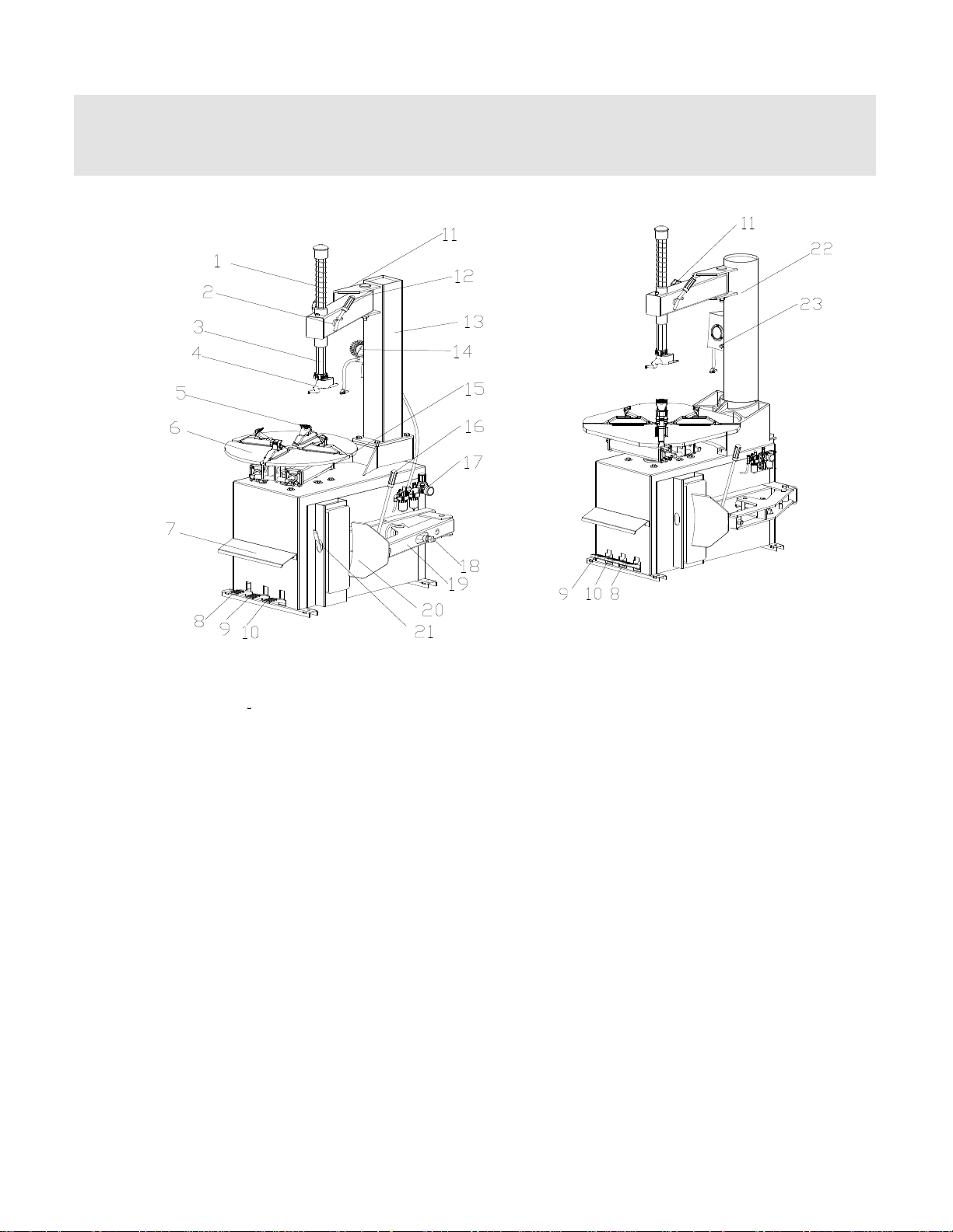
Know Your Unit - Compare thisillustration with the unit beforeplacing it into service. Maximum performance
and safety will be obtained only when allpersons using theunit arefully trained in its parts and operation. Each
usershouldlearn thefunctionandlocationofall controls.Prevent accidents and injuries by ensuring the unit is
properly installed, operated, and maintained.
图 2 图 3
FIG 2
1 vertical shaft spring 2 rocker valve 3 hexagon shaft 4 demount head
5 claw 6 turntable 7 operation label 8 turntable pedal
9 clamp pedal 10 tire press pedal 11 limit handle 12 lock handlel
13 column 14 inflation gun 15 clamp cylinder 16 blade handle
17 air source fitting 18 bead breaking cylinder 19 tire press arm 20 bead breaking blade
21 crowbar 22 air tank 23 inflation gauge box
CHAPTER Ⅲ INSTALLATION AND CALIBRATION
Before installation, carefully read this manual. The unauthorized change on the parts and spare parts of the machine
will cause damage to the machine. Installation personnel should have the specific electrical knowledge. Operators
must be trained and authorized. Before installation, carefully read the equipment list. If any question, please contact
our company.
To ensure the success of the installation, please prepare the following common tools: Two wrenches(10″), one
socket wrenches, one hexangular wrench, one tung and one screw driver. One hammer and one multi-purpose
meter.
3.1 DEPACKAGE
3.1.1 According to the de-package instruction on the package box, detach the box and remove the package
material. Check to see if the machine has damage or not and if the spare parts are completed.
FIG 3
3.1.2 Keep the package material far away from the working site and remove it properly.
Page 9
3.2 INSTALLATION
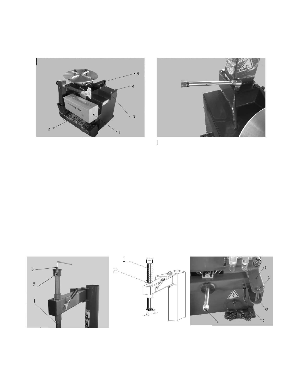
3.2.1 After un-packaging the package carton, take out accessory boxes(FIG 4-1),bead breaking arm(FIG 4-5)
and column assembly(FIG 4-2). Position the body according to the FIG1.4. Remove the bolt(FIG 4-4), elastic washer
and plate washer on the body.
FIG 4 FIG 5
3.2.2 Place the column on the body. The direction of the warning label is forwards. Make the holes on the column
base plate align to thread holes on the body. Once again assemble the removed the bolt(3.2.1), elastic washer
and plate washer and plate washer removed in 3.2.1 The torque is 70 N·M(FIG5)Use torsion wrench to tight.
3.2.3 Use the wrench to remove the screw(FIG 6-3)hexangular shaft(FIG6-1)and take off the vertical shaft cap
(FIG 6-2). When removing the screw on the vertical shaft cap, you need to use the lock handle to lock the
hexangular shaft to avoid sliding off to avoid damage to the machine or injury to personnel!
Install the vertical shaft spring(FIG7-1)on the vertical shaft. Mount the vertical shaft cap and mount the removed
screw and assemble the hand wheel into the nut bushing of the rocker arm(FIG 7-2)。
3.2.4 Remove the lock nut at the front end of the bead breaking cylinder piston rod(FIG 8-1)and use the wrench to
remove the nut on the bead breaking arm bolt(FIG8-4) Removethe bolt(FIG8-3)and hang the spring(FIG8-2)
FIG 6
FIG 7 FIG 8
Page 10
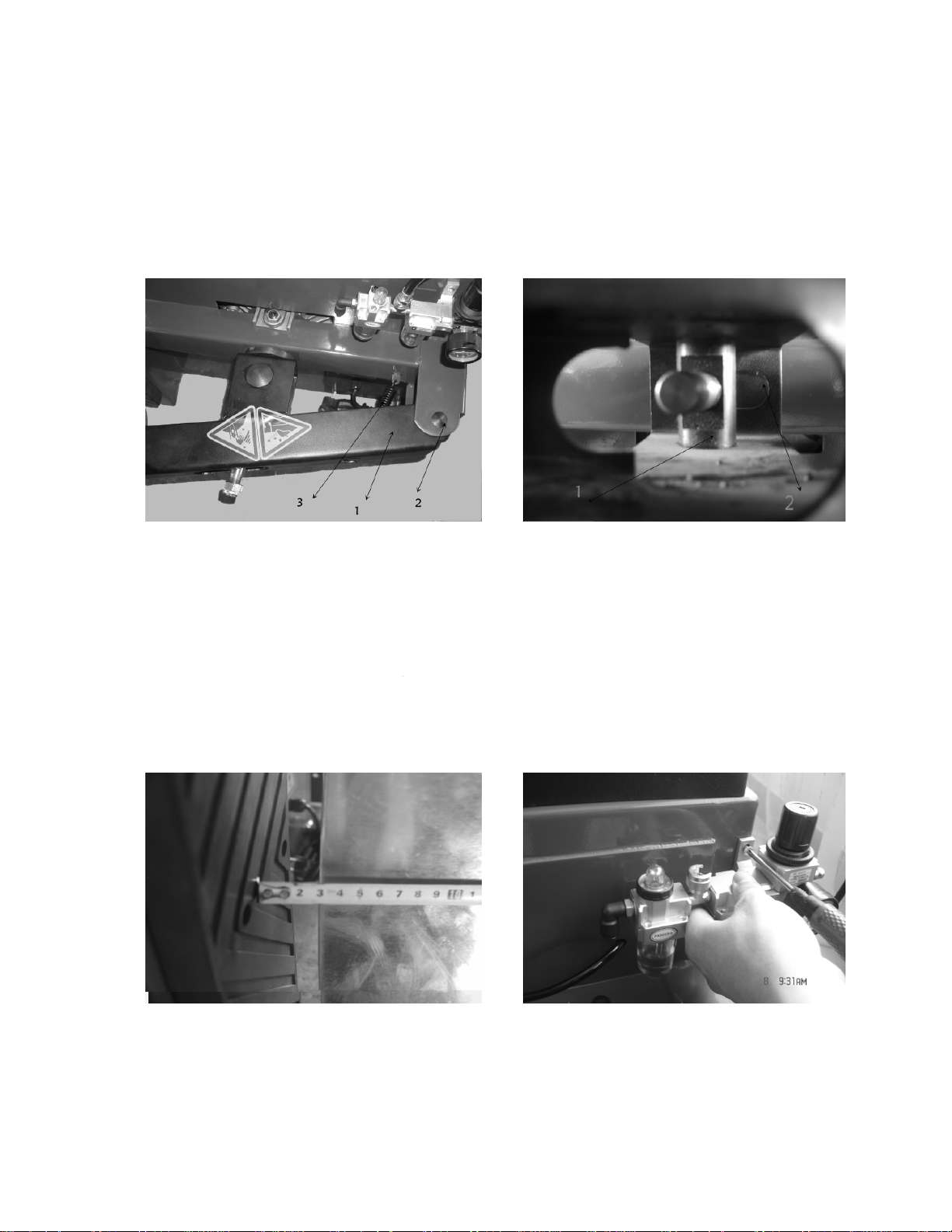
3.2.5 Position the bead breaking arm shaft bushing into the bead breaking support plate on the body(FIG 9-1)to
align the hole and install the bead breaking bolt(FIG 9-2)and assemble the nut to lock(FIG 8-4). Insert the piston
rod(FIG10-2)through the hole of the bead breaking slide bushing(FIG10-1). The surface of the slide bushing should
be outwards(FIG 10). Assemble the removed nut(FIG 8-1)into the front end of the piston rod. The nut will be
assembled. The distance from the edge of the bead breaking blade to the bead breaking rubber is 30~40mm
(FIG11). Hang the spring.(FIG9-3)。
FIG 9 FIG 10
Note:If the machine is the one with the quick inflation, please open the side panel and insert 2 pieces of Ø12pu hose
at the inlet of the quick deflation valve into the 2 Ø12nozzle and then install the side panel.
3.2.6 If being equipped with the tool box, you must fix firmly and the column completely installed.
3.3 AIR SOURCE FITTING INSTALLATION:
When the machine leaves the factory, the air source fitting has been detached and placed in the accessory box.
3.3.1 Take out the air source fitting from the accessory box and the screw and remove the oil and dust. Use the
screw to fix it on the right side of the body(fig12)。
FIG 11 FIG 12
Page 11

3.3.2 Connect the air hose. Detach the adapter on the ø8 PU hose on the side wall of the body and insert it into the
elbow. See the fig13/14. The adapter is to keep the hose from sliding into the body.
FIG 13 FIG 14
3.3.3 Connect the inflation gun or inflation gauge box: Inlay the adapter of the inflation gun or inflation gauge box
into the groove (fig15) on the open nut on the air source fitting. Tighten the open nut and then connect the air source.
3.3.4 Air source has been adjusted before ex-factory. If it needs change, adjust again:Pressure: Lift up the pressure
adjustable button( FIG16-1)and twist clockwise and the air pressure will increase. Meanwhile, if counterclockwise,
the air pressure will decrease. Oil Feed:Use screw driver to twist the screw(FIG16-2). If clockwise, the oil dropping
speed will slow. If counterclockwise, it will become faster.
FIG 15
FIG 16
Page 12

CHAPTER Ⅳ BEAD LOOSENING, DEMOUNT AND MOUNT TIRE
OPERATING INSTRUCTIONS
The unit must be properly operated and properly maintained to help avoid accidents that could damage
the unit and injure the operator or bystanders. This section of the Operating Instructions
manual reviews the basic operations and use of controls. These instructions should be reviewed with all
employees before they are allowed to work with the machine. Keep these instructions near the machine for
easy reference.
CAUTION - This machine may operate differently from machines you have previously operated.
Practice with a regular steel wheel and tire combination to familiarize you with the machine’s operation
and function.
4.1 BEAD LOOSENING, and DEMOUNT TIRE
4.1.1 Deflate the air in the tire completely and pull out the core. Use the special tool to detach any wheel weights on
the rim (FIG17). NOTE: Loosening the beads on a partially or fully inflated tire is unsafe and causes excessive
wear on pivots with friction against the bumper pads. Deflate the tire completely to prolong the life of your machine.
FIG 16
FIG 17
4.1.2 Place the tire between the bead breaking blade and tire pressing runner clog. (Fig18) Then step down the tire
press pedal to detach the rim from the tire(fig2-10 or 3-10). WARNING – Watch your fingers and legs! Repeat the
same operation on the other parts of the tire to make the tire completely detached from the rim. Place the wheel with
the tire detached from the rim on the turntable and step the clamp pedal(fig2-9; 3-9) to clamp the rim. Place the
wheel WITH DROP CENTER UP on the turntable, and clamp in position. Press the wheel down while clamping. You
can select the outer clamp and inner clamp to clamp the wheel according to the rim type. To detach the lip smoothly,
you can use the brush to spread the lubricant or thick soap
liquid between the lip and rim.
WARNING - TO MINIMIZE THE RISK OF SCRATCHING
ALLOY and PAINTED RIMS, THESE SHOULD BE
CLAMPED FROM THE OUTSIDE.
FIG 18
WARNING! - ON CHEVROLET CORVETTE WHEELS WITH
THE OPTIONAL LOW PRESSURE SENSOR INSTALLED,
BREAK THE BEAD AT 90 DEGREES OFFSET FROM THE
VALVE STEM. DAMAGE TO THE WHEEL WILL RESULT
IF THE BEAD IS BROKEN AT ANY OTHER POINT ON THE
RIM.
Page 13

4.1.3 Position the hexangular shaft (FIG 2-3) to the working position to make the demount tool close to the rim of the
wheel. And use the hand wheel (FIG 7-2) to push against the rocker arm and then use the lock handle( FIG 2-12) to
lock. Position the mount/demount head in contact with the rim edge and lock it into place: the tool automatically
moves away from the rim edge vertically. Turn the adjustment knob until the mount/demount head clears from the
rim flange about 2 mm (1/16"): this is necessary to avoid rim damage (FIG19).
The angle of the demount tool has been calibrated according to the standard rim. Adjust as necessary for different
size rims.
FIG 19
4.1.4 Use the bead lifting crowbar to detach until the lip to the hump of the demount tool (FIG20). Press down the
turntable rotation pedal(FIG2-8)to rotate the turntable clockwise until the entire lip completely detached. Depress
the tabletop pedal to rotate the wheel clockwise. The demount head will guide the upper bead up and over the edge
of the wheel. Push down on the tire across from the demount head during table top rotation to utilize the drop center
area of the wheel. This reduces the tensional force on the top or first bead during demount. If desired, the bead lifting
tool can be removed after lifting the bead onto the finger.
Lift and hold the tire at an angle so that the lower bead is resting in the drop center directly across from the demount
head, and is loose below the demount head. Insert the smooth curved end of the bead lifting tool down over the
forward end of the mount/demount tool and below the lower bead. Lift the bead up and over the knob on the demount
head. Depress the table top pedal to rotate the wheel. The demount head will guide the bead up and
over the edge of the wheel. Continue rotation until lower bead is demounted.
FIG 20
CAUTION
At times during the mounting and demounting procedure, the bead lifting tool may encounter resistance or
come under load. Keep one hand firmly on the tool to avoid possible tool disconnect. Use the reversing feature to back
out of jam ups.
Normal table top rotation for demounting is clockwise. Depress the table top pedal to rotate this direction. To rotate
the table top counterclockwise, lift the pedal up with your toe.
Page 14

In the process of demounting tire, you should keep your hands and the other parts of your body as well as clothing
from the movable parts to prevent injury.
4.1.5 If handling the tube tire, to avoid the damage on the tube, you should keep the valve stem of the tire 10cm from
the right side of the demount tool when demounting. When handling the tube tire, take out the tube and then move
the lower lip upwards to the upper edge of the rim and then repeat the above steps to detach the other lip.
4.2 MOUNT TIRE:
This information must be read and followed carefully to prevent accidents and injuries during mounting.
Check tire and wheel carefully before mounting. Make sure the tire bead diameter and wheel diameter match exactly.
Consult the Rubber Manufacturer's Association for approved rim widths for tire sizes. Attempts to force a bead seat on
mismatched tires and wheels can cause the tire to violently explode, causing serious
personal injury or death to operator and/or bystanders.
Never mount a tire and wheel handed to you by anyone without checking both tire and wheel for damage and
compatibility. Be extra cautious of persons without knowledge of tire service. Keep bystanders out of service area.
Never mount a damaged tire. Never mount a tire on a rusty or damaged wheel. Damaged tires and/or wheels may
explode. If you damage the tire bead during mounting, STOP! Remove the tire and mark it as damaged. Do not mount a
damaged tire.
WARNING - LIBERAL LUBRICATION OF THE TIRE AND RIM IS NECESSARY TO MOUNT TIRE CENTERING
CORRECTLY AND GET A PROPER ON THE RIM. BE SURE YOU ARE USING APPROVED LUBRICANT ONLY.
WARNING - OBSERVE THE ROTATION DIRECTION OF THE TIRE, IF REQUIRED. SOME TIRES HAVE A
COLOR DOT THAT MUST BE KEPT ON THE OUTSIDE OF THE WHEEL.
4.2.1 Clean the dirt and rust on the rim and lock it on the chuck. Lock the rim on the turntable.
4.2.2 Spread the lubrication liquid or soap liquid around the tire beads. Tilt the tire against the rim and keep the front
end upwards. Press down the hexangular shaft to move the demount arm to contact with the rim and lock. The left lip
above the tail of the demount tool and the right lip will be positioned under the front end of the demount tool (FIG 21).
Depress table top pedal and rotate the wheel to mount the lower bead. Use the drop center of the wheel to reduce
the tensional force on the bead by pressing down on the tire directly across from the mount head. Rotate table top
until lower bead is fully mounted.
FIG 21
For top bead, rotate the table top until the valve stem is at the 5 o'clock position. Lift the upper bead up and over the
rear of the mount head. Press down on the tire between the mount head and the valve stem to hold the tire in the
drop center. Depress table top pedal and rotate tire until the bead is mounted. Continue to press down on tire during
the remaining mounting process.
If table top rotation stalls, reverse the table top momentarily until the tire bead is again loose on the wheel. Reposition
the tire on the mount head; make sure the bead is correctly positioned in the drop center of the wheel, then attempt
mounting again.
4.2.3If there is tube, place it in the tire and plug the core. And assemble the lip according to the above mentioned
Page 15

step (FIG22). In the process of clamping the rim, do not reach your hands in between the rim and the claw to avoid
the damage to the personnel.
FIG 23FIG 22
4.2 INFLATION:
CAUTION, WARNING, DANGER
Check for proper inflation gauge operation. Accurate pressure readings are important to safe tire inflation. Refer to the
Operating Maintenance section of this manual for instructions.
If the rim has been clamped from the outside for tire mounting, release the clamps, lift the tire, and move the clamps to
the center of the table top. THE RIM MUST BE UNCLAMPED WHEN INFLATING BUT ONLY AFTER BEADS
HAVE BEEN SEATED.
If the wheel/tire has a diameter larger than 14 inches and is difficult to bead seal, the clamps should be moved to the
center of the table top for the bead seal operation.
Tire failure under pressure is hazardous. This tire changer is not intended to be a safety device to contain exploding
tires, tubes, wheels, or bead sealing equipment. Inspect tire and wheel carefully for
match, wear, or defects before mounting. Always use approved tire bead lubricant during mounting and inflation.
The inflation pedal, located at the rear of the left side of the machine, controls the flow of air through the inflation
hose.
NOTE: The clip-on chuck on the end of the hose should always be an open style with all parts in proper working order.
ATTENTION! WHEN OPERATING THE BEAD SEATER IT IS MANDATORY TO WEAR SAFETY GLASSES TO
PROTECT EYES.
The Inflation pedal operates in 3 positions as described below.
Page 16

Position 1 (All the way up at rest) - Tire Pressure – With the inflation hose attached to the tire valve and the pedal in
this position, the air gauge will register the air pressure in the tire. Whenever your foot is removed from the pedal, it
will return to this position.
Position 2 (Pushed down to the mid level) - Tire Inflation – This is the first activated position. With the inflation hose
attached to the tire valve and the pedal in this position, line pressure is allowed to flow through the valve and
into the tire for inflation. Tire pressure is not indicated on the gauge in this position. The pedal must be released to
read pressure.
Position 3 (Pushed down all the way to lowest level) - Bead Sealing – This is the second and last activated position.
With the inflation hose attached to the tire valve and the pedal in this position, line pressure is allowed to flow through
the valve and to the inflate bead seal jets on the table top for bead sealing.
Use Position 3 for bead sealing only. Do not use this position without a tire and wheel positioned on the table top. Dirt
and debris could be blown into the air with enough force to injure the operator or bystanders. Do not use this position to
inflate a tire.
When the inflation pedal is held in position 2, the pressure should be checked every few seconds to prevent over
inflation. This cycling helps to prevent over inflation of the tire. Tires can still be over inflated and explode with the
use of this technique and if all of the instructions in this manual are not followed completely. It is the operator's
responsibility to follow all instructions and to control inflation pressure as specified in these instructions. Tires
requiring inflation beyond 60 PSI should be inflated in a safety cage.
Tire inflation is performed in three steps: Bead Seal, Bead Seat, and Inflation.
Bead Sealing
1. Position valve stem in front of operator and connect the inflation hose. Hold tire up against upper edge of the
wheel. Be sure tire’s top bead is over the bottom of the valve stem.
2. Depress inflation pedal to position 2 and hold about 1 second to begin air flow through tire valve, then depress
pedal to position 3 and hold briefly – less than 1 full second. The blast of air from the jets will expand tire and seal the
beads.
3. Release the inflation pedal and allow it to return to position 1. Verify that both beads are completely sealed to the
wheel. Repeat these steps if beads have not sealed. It may be necessary to wait a few seconds for the air storage
tank to recover before attempting again.
Note: If tire and wheel are properly lubricated and operator cannot achieve bead seal after 3 or 4 attempts, the valve
core may be removed from the valve stem to allow more air flow into the tire to assist with bead seal. After bead seal
is achieved, remove the chuck and reinstall the valve core.
Bead Seating
Operator should keep hands, arms, and entire body away from the tire during the remaining bead seat and inflation
procedures. Do not stand over tire, as personal injury could result.
NEVER increase air pressure to exceed 40 PSI when attempting Bead Seat. If operator is unable to obtain Bead Seat,
something is wrong. Deflate tire completely, inspect tire and wheel, and correct any problems
found, relubricate both tire beads, and reattempt Bead Seal and Seat procedures. Follow all safety instructions in this
manual and on machine.
1. Once tire pressure is indicated on the air gauge (inflation pedal in position 1; foot removed from pedal), continue to
inject air into the tire in short intervals. Check the pressure frequently. Stand back during bead seat. Keep hands,
arms, and entire body away from tire during this procedure. Tire beads should move outward and "pop" into their
bead seat position as pressure inside the tire increases. If this does not happen, a problem exists. Investigate
carefully.
Check tire pressure frequently. Never exceed 40 PSI while seating beads. Once seated, never exceed tire
manufacturer's recommended air pressure. Tires can explode, especially if they are inflated beyond their limits. At all
pressure levels when inflating through the valve stem, keep hands, arms, and entire body away from inflating tire.
An exploding tire, wheel, or bead sealing equipment may propel upward and outward with sufficient force to cause
serious injury or death to operator or bystander.
Inflation
NEVER exceed tire manufacturer's recommended air pressure. Tires can explode, especially if inflated
Page 17

beyond these limits. Keep hands, arms, and entire body back from inflating tire. Avoid distraction during inflation.
Do not stand over tire
Inflation
wider
range.
seal on top side
Check tire pressure frequently to avoid over inflation. Excessive pressure can cause tires to explode, causing serious
injury or death to operator or bystander. THE RIM MUST BE UNCLAMPED WHEN INFLATING BUT ONLY AFTER
BEADS HAVE BEEN SEATED.
This machine is equipped with an inflation gauge for monitoring the inflation of the tire and the inflation pressure(FIG
22).
1. Connect the inflation hose with the tire air core. See
FIG23. Make sure both beads are seated. When both
beads are seated, the tire is ready for inflation.
2. Replace the valve core if it was removed.
3. Depress the inflation pedal to position 2 to inflate the
tire. Release air pressure from tire by pressing the
manual release valve button (inflation hose must be
attached to the valve stem).
STAGES OF INFLATION
Review these descriptions and diagrams carefully.
Refer to them as necessary during bead sealing,
bead seating, and inflation to verify that you are
proceeding properly and safely.
Bead Sealing
A140 PSIair blastfrom thetable top jetscreates an
air curtain to aid in bead sealing. Never exceed
10 PSI in the tire during bead sealing. The tire
will contain about 1/2 to 2 PSI when bead seal
is obtained.
Bead Seating
Bead seating usually occurs on the long tapered
side of the wheel first and the shorter side last. Bead
seating will usually require at least 7 PSI in the tire.
40 PSI is the maximum safe pressure at this stage
regardless of tire operating pressure.
Most European import cars and many aftermarket
alloy wheels are very tight and can be difficult to
bead seat. Also note that asymmetrical hump and
run-flat tires are extremely difficult to bead seat.
Follow tire manufacturer's recommended procedure
for bead seating.
Requires rubber lubricant on
bothupperand lower beads
Table topjets
Requires visual confirmation of bead seat
Air flow through valve requires
about 140 PSI air pressure drop to
insure sufficient flow on difficult
tires.
Lift tire up to assist
Usually last to "pop" is top side
during inflation.
After the beads are seated, the tire is inflated.
Do not inflate the tire above the manufacturer's
recommended pressure as stamped on the tire
sidewall. The typical inflation pressure for
automobile tiresis between24 and45 PSI. Light
truck inflation pressure typically covers a
Do not stand over
tire during inflation.
Page 18

DANGER!
17.5, etc.
MISMATCHED TIRES AND WHEELS
Never attempt to mount and inflate mismatched
tires and wheels.
Mismatched tire and wheel combinations
explode, causing personal
injury or death to operator and bystanders.
For safety, do not attempt to mount and inflate
mismatched tires and wheels.
Half Size Tires
14.5, 15.5, 16.5,
Even Size Wheels
14.0, 15.0, 16.0,
17.0, etc.
Even Size Tires
14.0, 15.0, 16.0,
17.0, etc.
Note the gap
in this area
Note 15°
Bead Seat
Bead will not
seat properly
HalfSize Wheels
14.5, 15.5, 16.5,
17.5, etc.
Page 19

READ…
Mounting and inflating the wrong size tire can get you hurt. Read the size on the tire and make sure it matches the
rim. Be especially careful about putting a smaller tire on a larger rim, such as a 16-inch tire on a 16.5-inch rim.
Inflation of a mismatched tire and rim can cause an explosion.
INSPECT…
Before you put any tire on a rim, inspect the rim for rust, tough spots, bent edges, or cracks that could prevent the
tire from seating right. If you spot any of these problems, don’t mount the tire until the rim has been checked by your
shop foreman. Inspect the tire for bead damage.
MOUNT…
Once you’ve made sure the tire is OK and the right size and the rim is OK, mount the tire safely. NEVER, ever lean
over the tire when you’re inflating it. If a tire does explode, it will go straight up. You don’t want to be over the tire if
that happens. Also, never over-inflate the tire, even if the bead doesn’t seat. Never inflate over 40 PSI. If the tire
wasn’t seated, something is wrong. Deflate the tire and check it and the rim again. If it doesn’t work the second time,
try another tire.
FAILURE TO READ AND FOLLOW ALL WARNINGS AND INSTRUCTIONS IN THIS MANUAL CAN LEAD TO
SERIOUS PERSONAL INJURY OR DEATH TO OPERATOR OR BYSTANDER.
THE OWNER IS RESPONSIBLE FOR MAINTAINING THE OPERATION INSTRUCTIONS AND
DECALS FOR THIS MACHINE AS WELL AS PROVIDING THEM TO ALL OPERATORS.
TIRE FAILURE UNDER PRESSURE IS HAZARDOUS!
This tire changer Will Not Restrain Exploding Tires, rims or other related equipment.
TIRES CAN EXPLODE, ESPECIALLY IF INFLATED BEYOND SPECIFIED LIMITS. DO NOT EXCEED
TIRE MANUFACTURERS RECOMMENDED AIR PRESSURE. AN EXPLODING TIRE, RIM, OR BEAD SEATING
EQUIPMENT MAY PROPEL UPWARD AND OUTWARD WITH SUFFICIENT ENERGY TO CAUSE SERIOUS
INJURY OR DEATH TO OPERATOR AND/OR BYSTANDERS
19
Page 20

Chapter V MAINTANENCE & REPAIR
NOTE:
Only the qualified professional personnel can execute the maintenance. Before
any maintenance, Cut off the power .And ensure the maintenance personnel
can take charge of the power plug. Meanwhile, cut off the air supply and push the
air supply switch to the off position and completely deflate the residual air in the
machine. To correctly use the tire changer and prolong its working life, it is
necessary to periodically maintenance and repair according to the instruction
manual. Or the running and reliability of the machine will be affected and the
personnel near the machine or the operator will be injured.
The following position should be monthly maintenance:
Keep the machine and working area clean.
Use the diesel oil to clean the hexangular shaft (FIG24),Use the machine oil to lubricate.
Use the diesel oil to clean the turntable claw and its guide and use the lithium base oil to lubricate (FIG25),
20
Page 21

Periodically check the lubrication oil level in the oil fog device. If the oil level lower than the oil scale, please feed in
FIG 25
FIG 24
FIG26FIG 27
FIG 26
FIG 28
the SAE30 lubrication oil in time(FIG 26)
Periodically drain out the water and impurity in the oil water separator.
Periodically check and adjust the tension of the drive belt. Properly adjust the adjust nut in A and B to realize the
proper tension.(FIG27).
Check all the connect parts and tight the loosen bolt.
HEXANGULAR SHAFT & LOCK PLATE LOCK GAP ADJUSTMENT
When press downward the hexangular lock handle, the hexangular shaft
will vertically slide under the effect of the weight of the hexangular shaft
and return spring. When the lock handle rotate clockwise for about 100
degree, the cam connected to the handle will push up the lock plate to
lock the hexangular shaft. If you can not realize this situation, you can
reach the target to lock the hexangular shaft through adjusting the position
of the screws and nuts.(FIG 28)
LOCK
PLATE
CAM
LOCK
HANDLE
ADJUST
NUT
HEX
SHAFT
21
Page 22

CHAPTER VI INSTALLATION & OPERATION OF THE ASSISTANT ARM
6.1 INSTALLTHE LEFT ASSISTANT
6.1.1 PL330 left assistant can be equipped on the tire changer which can handle the tire with the diameter of 20″ to
help complete the demount on the stiff and low profile tire. We can use it to handle the work which if difficult and
impossible to do only by the operators.
Before installation, the power and air source must be cut off!
6.1.1 The left and right side of the base plate of body of the tire changer which can handle the tire with the diameter
of more than 20″ all have the installation hole for the left assistant prepared. Before installation, you can remove the
side panel and take off the installation rubber plug. If there being the tool box, you should detach the tool box.
6.1.2 Detach the package of the PL330assistant. Check the accessory according to the pack list. After confirmation,
takeout the base assembly(fig29) and install the screw and washer on it.
FIG 29 FIG 30
6.1.3 Push the platform of the base plate of the base assembly into the body through base plate on the left-back side
of the body. Align the thread hole to the reinforce hole and use the bolt and washer to fix.(fig30).
6.1.4 Install the body bracket(fig31-1)on the seat assembly. Align. Use the screw removed before to fix and not
tighten
6.1.5 Use the fix supporting bracket(fig32)to connect the body bracket and the body and insert the screw to fix.
6.1.6 Connect the air source hose(fig33-2)and use Y Tee to connect the outlet hose and the other end connect with
the inlet of the assistant pressure adjusting valve.
22
FIG 32FIG 31
Page 23

6.1.7 Connect the air source, insert the press cone roller connect rod(fig34-1)into the rotation shaft hole(fig 34-2)
FIG 36
FIG 38
of the rotation arm. Handle manual direction change valve to make the tip of the press cone roller coincide to the
center of the turntable(fig35). If not coincide, use the screw to adjust the position of the base to realize the proper
fit. After adjustment, fix the bolt.
FIG 34FIG 33
6.1.8 According to the fig36, fix the fix bracket on the body and fixes the tool box on the fix bracket and then use the
lock nut to tight.
FIG 35
6.1.9 As fig37, fix the cone support on the body bracket and install the press cone on the bracket.
6.1.10Loose the nut below the base and turn the screw clockwise until it against the ground and tight(fig38) and
install The side panel and tool box removed in the 6.1.1. At this moment, the installation of the left assistant
completed.
23
Page 24

6.2INSTALLTHE RIGHT ASSISTANT
6.2.1After detach the tire from the rim according to the instruction of the chapter IV, we can execute the following
operations.
6.2.2 First, position the claw according to the dimension of the tire and then clamp the rim by the claw and position
the tire press cone roller at the center of the rim(fig39). Push down the manual valve to press down the rim until the
external rim of the rim is lower than the surface of the claw.At this moment, you can immediately lock the rim. Lift up
the support arm and place it at the working position and take off the press cone roller and place it on the support.
6.2.3 Use the press(fig40-1)to press down the tire section by section rim detached from the mouth and use the
brush to spread the lubricant on edge of the lip. Position the demount tool(fig40-2)in the demount position. Place the
press beside of the demount tool to press down the lip and insert the crowbar below the demount tool in between the
rim and lip(fig41),Lift up the press and move it to the position opposite to the demount tool and press the lip into the
tire detach groove and then rotate the crowbar to lift the lip onto the demount tool(fig42). Rotate the turntable to
detach the upper lip.
FIG 42
6.2.4 DETACH THE LOWER LIP: Use the disk to lift up the bottom of the tire from the bottom of the mouth(fig48)
and detach the lower lip (fig43) according to the step(4.1.5).
FIG 44FIG 43
24
Page 25

6.2.5 MOUNT TIRE
First, according to the step(4.2.1)~(4.2.3), install the lower lip and use the press to press the lower lip as shown
In the fig45. Rotate the turntable by about 90°. And then clamp the press in the demount tool(fig46)andcontinually
rotate the turntable until the completion of the operation.6.2.5
FIG 45 FIG 46
CHAPTER ⅣTRANSPORTATION
When transport the machine must apply the original package and place
According to the mark on the package. The machine must be transported
by the forklift with the corresponding tonnage(FIG69)and the stacked
layer will not exceed 3layers.
CHAPTER Ⅳ ELECTCTRICAL AND PENUMATIC DRAWING
8.1.220V ELECTRICAL PRINCIPLE DRAWING
8.2.380V ELECTRICAL PRINCIPLE DRAWING
8.3.110V/220V ELECTRICAL PRINCIPLE DRAWING
8.4. PNEUMATIC PRINCIPLE DRAWING
FIG 47
25
Page 26

8.1. 220V ELECTRICAL PRINCIPLE DRAWING
PHASE MOTOR(220V) WIRING
MOTOR SWITH
PE
N L
SA
9 5 7 11 1 3
6
10
8 12
2
4
FU20A
BY CUSTOMER
由用户完成的安装
POWER CABLE 3X1.5mm2
电源线3X1.5mm2
QC
1
电机转向开关
LW5D-16
16A/500V
拆胎机
INTERNAL
内部连线
WIRING
0
2
U1
Z2 U2 V1
M
1ph
220V 1.1KW 1400rpm
TIRE CHANGER 1-
拆胎机单相电机220V接线原理图(通用)
DRAWING (UNIVERSAL)
26
Page 27

8.2. 380V ELECTRICAL PRINCIPLE DRAWING
BY CUSTOMER
由 用户 完 成 的 安装
POWER CABLE 4X1.5mm2
电 源线 4X 1 . 5mm
INTERNAL WIRING
MOTOR SWITH
电 机 转 向 开 关
拆 胎机
内 部连 线
TIRE CHANGER 3-PHASE MOTOR(380V) WIRING DRAWING (UNIVERSAL)
拆 胎 机 三 相 电 机 接 线 原 理 图 通 用 )
27
Page 28

8.3.110V/220V ELECTRICAL PRINCIPLE DRAWING
TIRE CHANGER DUAL VOLTAGE MOTOR ( II)
LINE BAN
K
MOTOR SWITH
VOTAGE SWITH
B
lue
R
ed
G
reen
220V
兰
110V
黄
电压转换开关
2W30A
PE
AC
L1
110V/220V
FU1
5
9
绿
10
6
红
11
7
12
8
1
2
L2
BY CUSTOMER
用户配置
FU2
FU1
3
4
FU2 40A
0
1
2
电机转向开关
LW5-40
40A/500V
Yellow
兰
4
黄
绿
2
U1 U2 U3 U4 Z1 Z2
U1
PE
红
6
U3
U2
U4
Z1
M
1
~
Z2
扒胎机双压电机连线图之二
115
接线排
TB-2506L
600V/25A
1.1KW 4P
110/220V 50 60HZ
28
Page 29

8.4. PNEUMATIC PRINCIPLE DRAWING
SEMI AUTOMATIC PNEUMATIC
SEMI AUTOMATIC PNEUMATIC
半自动气动原理图
φ70/20X262
φ70/20X310
φ70/20X262
φ186/20X150
φ70/20X310
φ186/20X150
半自动代快充型气动原理图
(IT)
29
Page 30

φ80/20X80
1 2 3 4 5 6
φ70/20X310
φ70/20X310
φ186/20X150
φ66/66.5X16
4
φ66/66.5X16
30
Page 31

CHAPTER Ⅳ TROUBLESHOOTING ANALYZE AND SOLUTION
CHAPTER REASON TROUBLESHOOTING
Turntable rotate in one direction. Universal switch contact burned Change Universal switch
Turntable does not rotate. Belt damage
Belt too loose
Motor or power source have problems
Universal switch contact damage
Turntable can not clamp the rim as
normal
Quadric and hexangular shaft
cannot lock
Chassis pedal not return. Pedal return spring damage Chang torsion spring
Motor not rotate or the output
torque not enough
Cylinder output force not enough Air leakage
Claw worn
Clamp cylinder air leakage
Lock plate not in position
Drive system jam
Capacitor broken down
Voltage not enough
Short-circuit
Mechanic fault
Air pressure not enough
Air Leakage air hose broken
Change belt
Adjust the tension of the belt
Check motor, power source and
power source cable
Change motor if motor burned
Change Universal switch
Change claws
Change the air leakage sealing parts
Refer to the chapter V
Remove the jam
Change capacitor
Wait for the restore of the voltage
Remove
Change sealing parts
Remove the fault
Adjust the air pressure to meet the
requirement
Change broken parts
pipe fitting broken
sealing head broken
loss of the sealing glue
Refill the sealing glue
31
Page 32

LC SERIES MACHINE OIL SAFETY DATA SHEET
MOBIL XHP 222
ITEM QUALITY STANDARD
Penetration rate25℃ mm/10 280
dropping point ℃ 280
anticorrosion passed
Basic oil viscosity 220
oxidize stability 100h pressure-drop kpa 35
water lose percentage79% 5
copper corrosion 1A
SAE30# LUBRICATION OIL
ITEM QUALITY STANDARD
density 15℃ 0.893
Flash point 224
Pour point ℃ -18
viscosity 40℃ 100
viscosity 100℃ 11.2
Viscosity index 97
2# LITHIUM BASE GREASE
ITEM QUALITY STANDARD
Penetration rate mm/10 278
dropping point ℃ 187
copper corrosion 100℃ 24h No change
oxidize stability(99℃ 100h) 0.2
anticorrosion(52℃ 48h) 1 level
similarity viscosity(-15℃、 10S¯¹)/(Pa·S) 800
water lose(35℃ 1h) % 8
CKC460 INDUSTRIAL GEAR OIL
ITEM QUALITY STANDARD
Viscosity 40℃ 461
Viscosity index 92
Flash point ℃ 212
Freezing point ℃ -26
copper corrosion100℃ 3h 1A
mechanical impurity 0.007
Pour point -10
32
Page 33

WEARABLE (OPTIONAL) PARTS LIST FOR 890IT SERIES
Item No Description Specification Quantity Parts Codes
1
2
3
4
5
6
7
8
9
10
11
12
13
14
15
16
Seal-Y Ring 5010202
O-Ring 5010097
Valve-A 6000227
Valve-B 6000222
Switch 5010055
Cam 6000211
Fork spring plate 6000204
Valve connecting rod 6000210
torsion spring 6000220
Hinge Tee 6000010
Hinge elbow 6000009
Front cover 6000004
Rear cover 6000003
Circlip 5010024
Rigid PU hose
PU hose
Ф6
Ф8
5509032
5509033
17 Crowbar Protector QT-20 5309016
18 Demounting Head
BT-4 5509015
Protector
19 Demounting Tail
BT-4 5509014
Protection Washer
20 Bead Breaker Blade
CT-A 5509018
Protector
21 Clamp Protection Cover KT-4 5509019
33
 Loading...