

Weather-Rite UHA30, UHA45, UHA100, UHA125, UHAX30 Installation, Operation & Service Manual
...Page 1
FOR YOUR SAFETY
If you smell gas:
1. Open windows.
2. DO NOT try to light any appliance.
3. DO NOT use electrical switches.
4. DO NOT use any telephone in
your building.
5. Extinguish any open flame.
6. Leave the building.
7. Immediately call your local gas
supplier after leaving the building.
Follow the gas supplier’s
instructions.
8. If you cannot reach your gas
supplier, call the Fire Department.
UHA-Series
Tubular Unit and Utility Heaters
(Low Profile Range)
Installation, Operation
WARNING
Fire Hazard
Keep all flammable objects, liquids and
vapors the minimum required clearances to combustibles away from
heater.
Some objects will catch fire or explode
when placed close to heater.
Failure to follow these instructions can
result in death, injury or property
damage.
WARNING
Improper installation, adjustment, alteration, service
or maintenance can result in death, injury or
property damage. Read the Installation, Operation
and Service Manual thoroughly before installing or
servicing this equipment.
Installation must be done by a contractor qualified
in the installation and service of gas-fired heating
equipment or your gas supplier.
& Service Manual
Models UHA[X][S]
30, 45, 60, 75, 100, 125
Installer
Please take the time to read and understand
these instructions prior to any installation.
Installer must give a copy of this manual to the owner.
Owner
Keep this manual in a safe place in order to provide
your service technician with necessary information.
© 2014 Weather-Rite LLC
Weather-Rite LLC
616 North 5
Minneapolis, MN 55401
Telephone: +1.612.338.1401
Fax: +1.612.338.6783
Toll Free: 800.589.3691
www.weather-rite.com
th
Street
P/N WR111100NA 11/14 Rev. H
Page 2

Page 3
POUR VOTRE SECURITE
Si vous sentez une odeur de gaz:
1. Ouvrir les fenêtres.
2. N’essayer pas d’allumer un appareil.
3. N’utiliser pas d’interrupteurs
électriques.
4. N’utiliser pas de téléphone dans votre
bâtiment.
5. Eteindre flamme nue.
6. Quitter le bâtiment.
7. Après avoir quitté le bâtiment, appelez
immédiatement votre fournisseur local
de gaz.
Suivre les instructions du fournisseur
de gaz.
8. Si vous ne pouvez pas joindre votre
fournisseur de gaz, appeler le service
d’incendie.
UHA-Series
Aérothermes Utilitaires à
échangeur tubulaire
(Gamme compacte)
AVERTISSEMENT
Risque d’incendie
Garder tous les objets, liquides ou vapeurs
inflammables à la distance minimale de
l’unité de chauffage requise avec les
matériaux combustibles.
Certains objets prendront feu ou exploseront
s’ils sont placés à proximité de l’unité de
chauffage.
Le non respect de ces instructions peut
entraîner la mort, des blessures corporelles
ou des dommages matériels.
Manuel d’installation,
d’operation, et de service
Modèles UHA[X][S]
30, 45, 60, 75, 100, 125
AVERTISSEMENT
L’installation, le réglage, la modification, la réparation ou
la maintenance inadapté peut entraîner la mort, des
blessures ou des dommages matériels. Lire attentivement
le manuel d'installation, d'utilisation et d'entretien avant
d’installer ou de réparer cet équipement.
L’installation doit être effectuée par un entrepreneur
qualifié dans l'installation et l'entretien d'appareils de
chauffage au gaz ou par votre fournisseur de gaz.
© 2014 Weather-Rite LLC
Installateur
Vouloir prendre le temps de lire et de comprendre ces
instructions avant toute installation. L’installateur doit
donner un exemplaire de ce manuel au propriétaire.
Propriétaire
Garder ce manuel dans un endroit sûr pour fournir les
informations nécessaires au personnel d’entretien.
Weather-Rite LLC
616 North 5
Minneapolis, MN 55401
Téléphone: +1.612.338.1401
Fax: +1.612.338.6783
Numéro sans fraís: 800.589.3691
www.weather-rite.com
th
Street
P/N WR111100FC 11/14 Rev. H
Page 4

Page 5
TABLE OF CONTENTS
SECTION 1: Heater Safety...................................................... 1
1.1 Manpower Requirements .............................................1
1.2 Safety Labels and Their Placement..............................1
1.3 California Proposition 65 ..............................................1
SECTION 2: Installer Responsibility .....................................5
2.1 Wall Tag .......................................................................5
2.2 Corrosive Chemicals....................................................5
2.3 National Standards and Applicable Codes...................5
SECTION 3: Critical Considerations .....................................6
3.1 Basic Information .........................................................6
3.2 Manufactured Units......................................................6
3.3 Location and Suspension ............................................6
3.4 Minimum Required Installation Clearances .................6
3.5 Ventilation ....................................................................6
3.6 Gas Supply ..................................................................6
3.7 Electrical Supply ..........................................................6
3.8 Vent..............................................................................6
SECTION 4: Clearances to Combustibles.............................7
4.1 Required Clearances to Combustibles.........................7
4.2 Clearances to Combustibles ........................................ 7
SECTION 5: National Standards and Applicable Codes...... 9
5.1 Gas Codes................................................................... 9
5.2 Aircraft Hangars ...........................................................9
5.3 Parking Structures and Repair Garages...................... 9
5.4 Electrical ......................................................................9
5.5 Venting ......................................................................... 9
5.6 High Altitude.................................................................9
SECTION 6: Heater installation............................................ 10
6.1 General ...................................................................... 10
6.2 Shelf Mounting and Suspension ................................ 10
6.3 Wall Mounting ............................................................10
SECTION 7: Venting..............................................................14
7.1 Changing Vent and Air Intake Orientation...................14
7.2 Venting........................................................................ 14
7.3 Vent Installation .......................................................... 14
7.4 Horizontal Venting....................................................... 15
7.5 Vertical Venting........................................................... 15
7.6 Length Requirements ................................................. 16
7.7 Vent Material............................................................... 16
7.8 Replacing an Existing Heater in a Venting System..... 16
SECTION 8: Air Supply......................................................... 21
8.1 Separated Combustion Installation ............................ 21
8.2 Building Ventilation..................................................... 21
8.3 Outside Combustion Air Supply ................................. 21
SECTION 9: Gas Piping ........................................................22
9.1 Connections............................................................... 22
SECTION 10: Wiring ..............................................................24
10.1 Positioning Thermostats...........................................24
10.2 Low Voltage Thermostat with One Heater................ 24
10.3 UHA[X][S] Internal Wiring Diagram..........................25
10.4 UHA[X][S] Ladder Wiring Diagram........................... 26
10.5 Electrical Connection to the Heater..........................27
SECTION 11: Operation and Maintenance ......................... 28
11.1 Pre-Start-Up Checks ................................................ 28
11.2 Begin Start-Up ......................................................... 28
11.3 Pressure Switch........................................................ 30
11.4 Turning Off the Heater.............................................. 30
11.5 External Controls...................................................... 31
11.6 Complete Start-Up ................................................... 31
11.7 Instruction to the User.............................................. 31
SECTION 12: User Instructions........................................... 32
12.1 Heater Operation..................................................... 32
12.2 Common User Controls........................................... 32
12.3 Lighting Instructions ................................................ 33
12.4 Simple Troubleshooting ........................................... 33
SECTION 13: Servicing ........................................................ 34
13.1 Servicing Instructions .............................................. 34
13.2 Burner Maintenance................................................ 34
13.3 Fan/Motor Assembly Maintenance .......................... 34
13.4 Heat Exchanger Maintenance ................................. 35
13.5 Gas Valve Maintenance........................................... 35
13.6 Flue Blower ............................................................. 35
13.7 Venting and Air Intake Pipe ..................................... 35
13.8 Maintenance Checklist ............................................ 35
SECTION 14: Troubleshooting............................................. 37
14.1 General.................................................................... 38
14.2 Troubleshooting For Automatic Ignition Burner
Systems.................................................................. 39
14.3 Troubleshooting for Flame Supervision System....... 40
14.4 Troubleshooting for Gas Valves ............................... 41
14.5 Troubleshooting for Flue Blower .............................. 41
SECTION 15: Replacement Parts ........................................ 42
15.1 Gas Valve ................................................................ 42
15.2 Burner Injectors....................................................... 43
15.3 Ignition Electrode and Flame Probe ........................ 44
15.4 Heat Exchanger....................................................... 45
15.5 Louver and Louver Springs ..................................... 45
15.6 Flue Blower Vertical Installation for UHA[X][S]
30 - 75 Only............................................................. 46
15.7 Pressure Switch....................................................... 47
15.8 Ignition Control ........................................................ 47
15.9 Axial Fan/Guard/Motor Assembly ............................ 47
15.10 Limit Switches........................................................ 48
SECTION 16: Specifications................................................ 49
16.1 Dimension Data....................................................... 49
16.2 General Technical Data Table.................................. 50
16.3 Technical Data Table................................................ 50
SECTION 17: WEATHER-RITE
™
UHA-Series Warranty....... 51
All rights reserved. No part of this work covered by the copyrights herein may be reproduced
or copied in any form or by any means - graphic, electronic, or mechanical, including
photocopying, recording, taping or information storage and retrieval systems - without the
written permission of Weather-Rite LLC.
© 2014
Weather-Rite LLC
Printed in U.S.A.
Page 6

Page 7

TABLE OF FIGURES
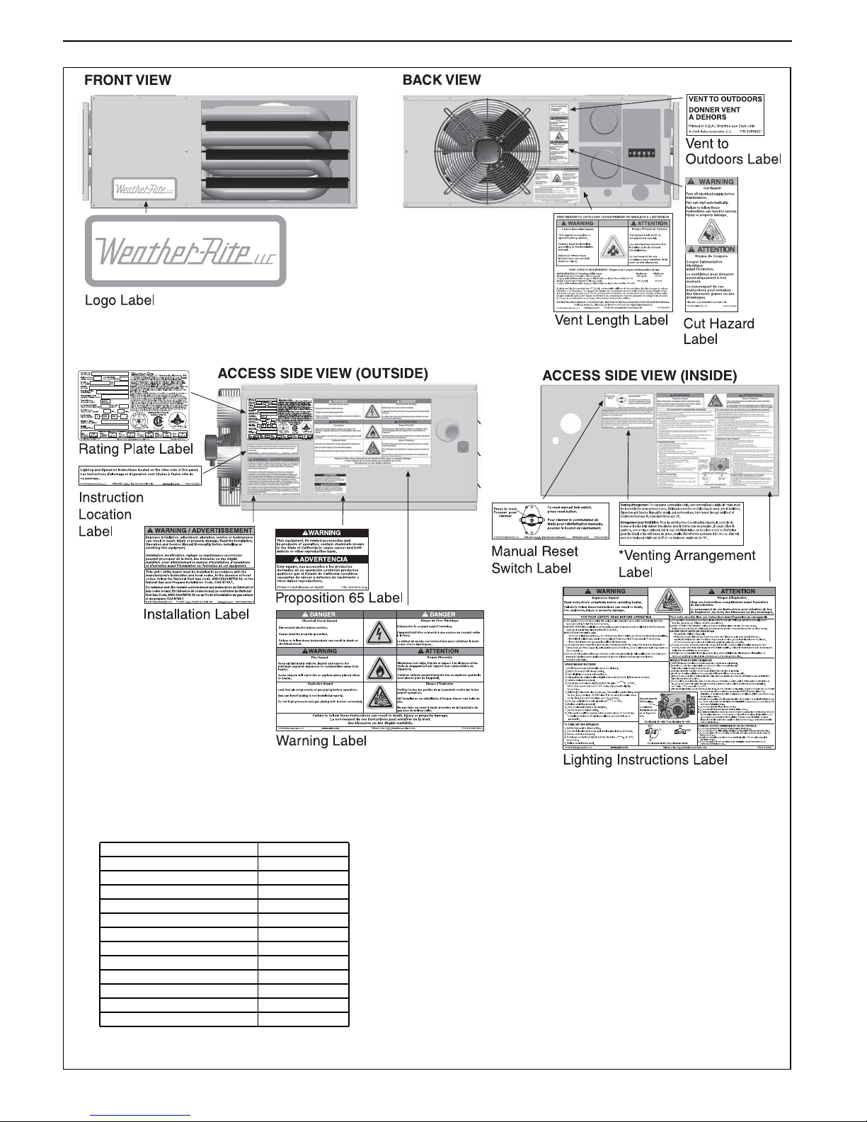
Figure 1: UHA[X][S] 30 - 45 Label Placement...........................2
Figure 2: UHA[X][S] 60 - 75 Label Placement...........................3
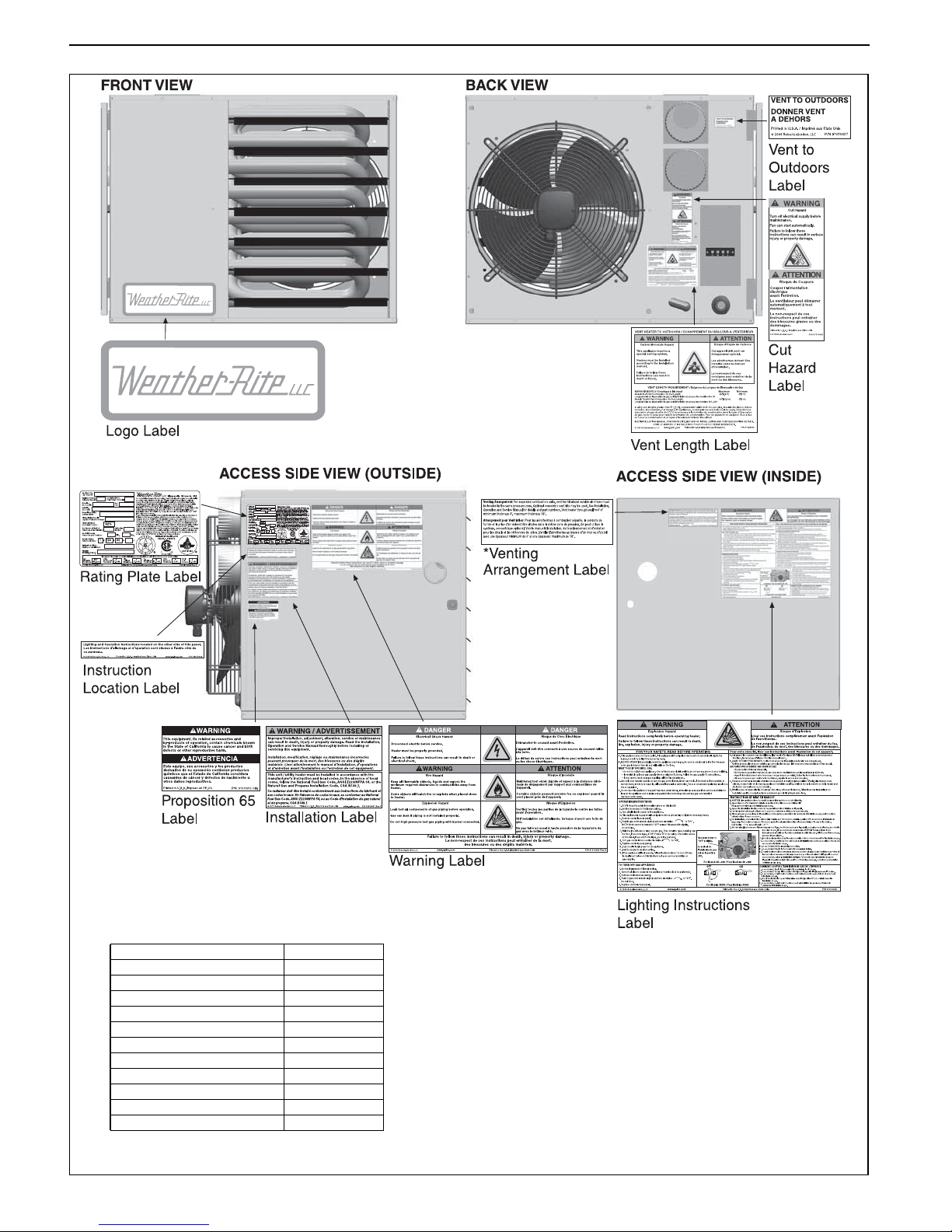
Figure 3: UHA[X][S] 100 - 125 Label Placement .......................4
Figure 4: Installation Clearances and Clearances to
Combustibles............................................................. 8
Figure 5: Suspension Methods ............................................... 11
Figure 6: Shelf-Mounting Methods.......................................... 11
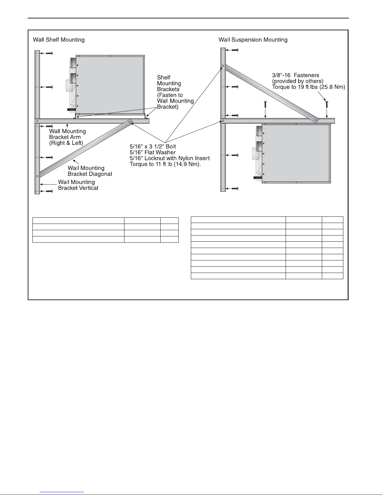
Figure 7: Wall Shelf Mounting and Suspension ......................12
Figure 8: Vertical Louvers........................................................ 13
Figure 9: Vent and Roof Detail ................................................17
Figure 10: Standard Vented Heater - Vertical and Horizontal
Vent Termination.....................................................17
Figure 11: Standard Vented Heater - Common Vertical Vent
Termination ............................................................18
Figure 12: Separated Combustion Heater - Vertical and
Horizontal Vent Termination ................................... 19
Figure 13: Concentric Vent Box............................................... 19
Figure 14: Concentric Vertical and Horizontal Vent
Termination - Separated Combustion Heater.........20
Figure 15: Gas Connection .....................................................23
Figure 16: Automatic Burner Control Sequence...................... 29
Figure 17: Gas Valve for Models UHA[X][S] 30 - 45................ 29
Figure 18: Gas Valve for Models UHA[X][S] 60 - 125.............. 30
Figure 19: Manual Reset Limit Switch..................................... 33
Figure 20: LED Diagnostic Codes...........................................33
There are references in this manual to various trademarks. All trademarks mentioned herein, whether registered or not, are the
property of their respective owners. Weather-Rite LLC is not sponsored by or affiliated with any of the trademark or registered
trademark owners, and makes no representations about them, their owners, their products or services.
Page 8

Page 9
SECTION 1: HEATER SAFETY
Your Safety is Important to Us!
This symbol is used throughout
the manual to notify you of
possible fire, electrical or burn
hazards. Please pay special
attention when reading and
following the warnings in these
sections.
Installation, service and, at a minimum, annual
inspection of heater must be done by a contractor
qualified in the installation and service of gas-fired
heating equipment.
Read this manual carefully before installation,
operation or service of this equipment.
Not all heaters are approved for residential
installation. Check the heater’s silver rating plate for
residential approval status. Heaters that do not have
residential approval must not be installed in
residential spaces. These instructions, the layout
drawing, local codes and ordinances and applicable
standards that apply to gas piping, electrical wiring,
venting, etc. must be thoroughly understood before
proceeding with the installation.
Protective gear is to be worn during installation,
operation and service in accordance to the
Occupational Safety and Health Administration
(OSHA). Gear must be in accordance to NFPA 70E,
latest revision when working with electrical
components. Thin sheet metal parts have sharp
edges. To prevent injury, the use of work gloves is
recommended.
Before installation, check that the local distribution
conditions, nature of gas and pressure and
adjustment of the equipment are compatible.
This heater must be applied and operated under the
general concepts of reasonable use and installed
using the best building practices.
This equipment is not intended for use by persons
(including children) with reduced physical, sensory
or mental capabilities, or lack of experience and
knowledge, unless they have been given
supervision or instruction concerning use of the
equipment by a person responsible for their safety.
Children should be supervised to ensure that they
do not play with the equipment.
For additional copies of the Installation, Operation
and Service Manual, please contact Weather-Rite
LLC.
SECTION 1: HEATER SAFETY
1.2 Safety Labels and Their Placement
Product safety signs or labels should be replaced by
product user when they are no longer legible.
Please contact Weather-Rite LLC or your
WEATHER-RITE
™
independent distributor to obtain
replacement signs or labels. See Page 2, Figure 1
through Page 4, Figure 3.
1.3 California Proposition 65
In accordance with California Proposition 65
requirements, a warning label must be placed in a
highly visible location on the outside of the
equipment (i.e. near equipment's serial plate). See
label placement drawing on Page 2, Figure 1
through Page 4, Figure 3 for label location. Avoid
placing label on areas with extreme heat, cold,
corrosive chemicals or other elements. To order
additional labels, please contact Weather-Rite LLC
or your WEATHER-RITE
™
independent distributor.
1.1 Manpower Requirements
To prevent personal injury and damage to the
heater, two persons will be required for installation.
1 of 51
Page 10
UHA LOW PROFILE UNIT HEATER INSTALLATION OPERATION AND SERVICE MANUAL
Figure 1: UHA[X][S] 30 - 45 Label Placement
Description Part Number
Logo Label 91031104
Cut Hazard Label 91010430
Vent Length Label 91039505
Vent to Outdoors Label 91010427
Warning Label 91010429
Rating Plate Label 91010423
Installation Label 91010431
Instruction Location Label 91010433
Lighting Instruction Label 91010425
Venting Arrangement Label* 91010426
Manual Reset Switch Label 91010428
Proposition 65 Label 91070015
For separated combustion units only
2 of 51
Page 11
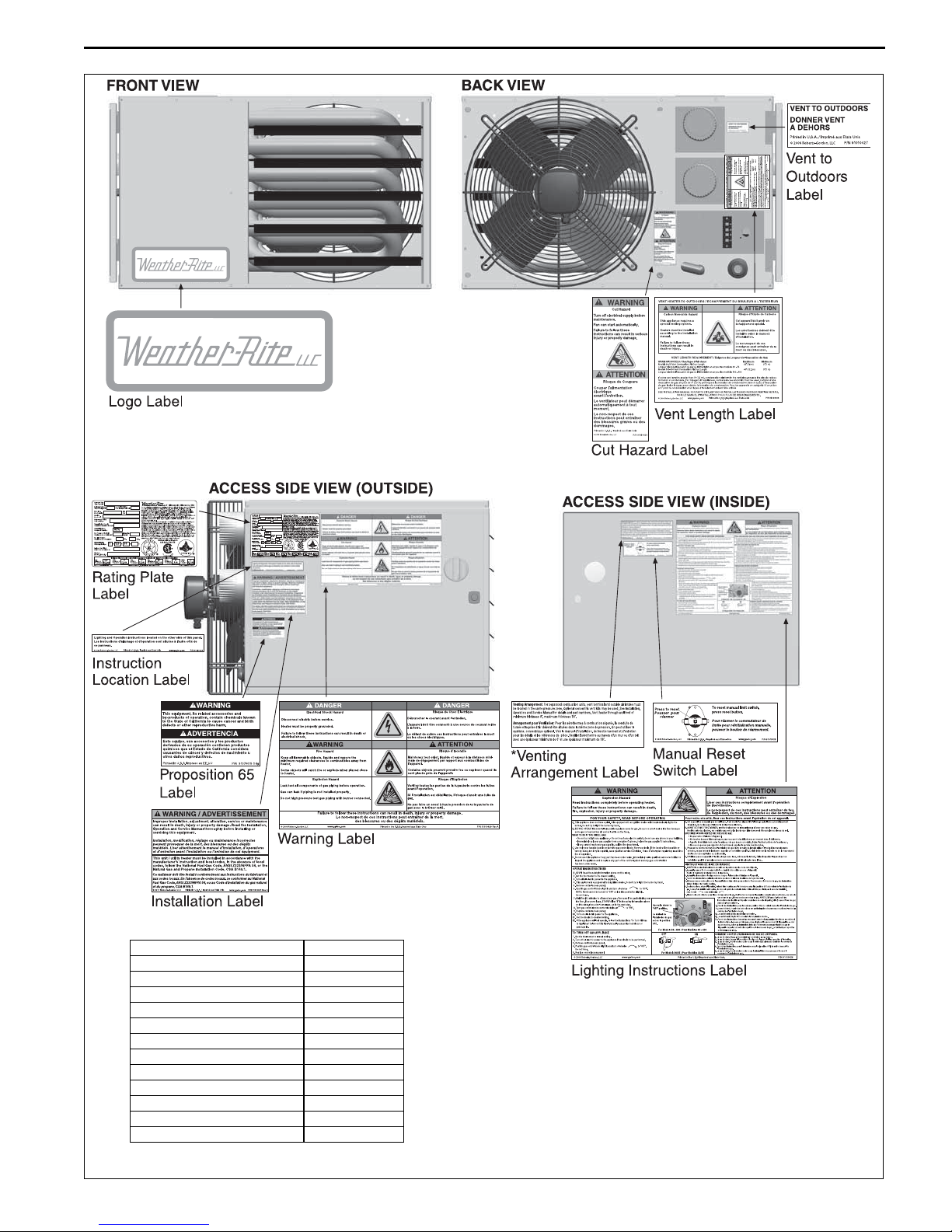
Figure 2: UHA[X][S] 60 - 75 Label Placement
SECTION 1: HEATER SAFETY
Description Part Number
Logo Label 91031104
Cut Hazard Label 91010430
Vent Length Label 91039505
Vent to Outdoors Label 91010427
Warning Label 91010429
Rating Plate Label 91010423
Installation Label 91010431
Instruction Location Label 91010433
Lighting Instruction Label 91010425
Venting Arrangement Label* 91010426
Manual Reset Switch Label 91010428
Proposition 65 Label 91070015
* For separated combustion units only
3 of 51
Page 12
UHA LOW PROFILE UNIT HEATER INSTALLATION OPERATION AND SERVICE MANUAL
Figure 3: UHA[X][S] 100 - 125 Label Placement
Description Part Number
Logo Label 91031104
Cut Hazard Label 91010430
Vent Length Label 91039505
Vent to Outdoors Label 91010427
Warning Label 91010429
Rating Plate Label 91010423
Installation Label 91010431
Instruction Location Label 91010433
Lighting Instruction Label 91010425
Venting Arrangement Label* 91010426
Proposition 65 Label 91070015
* For separated combustion units only
4 of 51
Page 13
SECTION 2: INSTALLER RESPONSIBILITY
The installer is responsible for the following:
• To install the heater, as well as the gas and
electrical supplies, in accordance with applicable
specifications and codes. Weather-Rite LLC
recommends the installer contact a Local
Building Inspector or Fire Marshal for guidance.
• To use the information given in a layout drawing
and in the manual together with the cited codes
and regulations to perform the installation.
• To install the heater in accordance with the
clearances to combustibles.
• To furnish all needed materials not supplied as
standard equipment.
• To plan location of supports, vents and air
intakes.
• To provide access for servicing.
• To provide the owner with a copy of this
Installation, Operation and Service Manual.
• To never use heater as support for a ladder or
other access equipment and never hang or
suspend anything from heater.
• To ensure there is adequate air circulation
around the heater and to supply air for
combustion, ventilation and distribution in
accordance with local codes.
• To ensure the heater is placed in an approved
application.
2.1 Wall Tag
A laminated wall tag is included with the heater as a
permanent reminder of the safety instructions and
the importance of the required clearances to
combustibles. Affix the tag by peeling off the backing
of the adhesive strips on the rear surface and
position the tag on a wall near the heater.
A copy of the wall tag (P/N 91040035) is illustrated
on the back cover.
Know your model number and installed
configuration. Model number and installed
configuration are found on the heater serial plate
and throughout the Installation, Operation and
Service Manual.
SECTION 2: INSTALLER RESPONSIBILITY
2.2 Corrosive Chemicals
CAUTION
Product Damage Hazard
Do not use heater in area containing
corrosive chemicals.
Refer to appropriate Material Safety Data
Sheets (MSDS).
Failure to follow these instructions can result
in product damage.
Weather-Rite LLC cannot be responsible for
ensuring that all appropriate safety measures are
undertaken prior to installation; this is entirely the
responsibility of the installer. It is essential that the
contractor, the sub-contractor, or the owner
identifies the presence of combustible materials,
corrosive chemicals or halogenated hydrocarbons*
anywhere in the premises.
* Halogenated Hydrocarbons are a family of chemical
compounds characterized by the presence of halogen elements (fluorine, chlorine, bromine, etc.). These compounds are
frequently used in refrigerants, cleaning agents, solvents, etc. If
these compounds enter the air supply of the burner, the life
span of the heater components will be greatly reduced. An outside air supply must be provided to the burners whenever the
presence of these compounds is suspected. Warranty will be
invalid if the heater is exposed to halogenated hydrocarbons.
2.3 National Standards and Applicable Codes
All equipment must be installed in accordance with
the latest revision of the applicable standards and
national codes. This refers also to the electric, gas
and venting installation. Note: Additional standards
for installations in public garages, aircraft hangars,
etc. may be applicable. See Page 9, Section 5.
5 of 51
Page 14

UHA LOW PROFILE UNIT HEATER INSTALLATION OPERATION AND SERVICE MANUAL
SECTION 3: CRITICAL CONSIDERATIONS
3.1 Basic Information
UHA[X][S] heaters have automatic ignition burners
for ON/OFF operation only.
3.5 Ventilation
It is important to ensure that there is adequate air
space around the heater to supply air for
3.2 Manufactured Units
A gas-fired, power-vented unit heater with tubular
heat exchanger. Units shall have a minimum of 82%
combustion, ventilation and distribution in
accordance with local and national code on Page
14, Section 7.
thermal efficiency. The standard unit shall consist of
a non-separated combustion design with an
aluminized heat exchanger and single stage gas
valve. Design and heat exchanger alternatives shall
be offered as follows:
• Separated Combustion: [S] A separated
combustion unit shall consist of a sealed
3.6 Gas Supply
It is important that the gas supply pipe is sized
correctly to provide the inlet pressure as stated on
the heater serial plate. The gas supply pipe and
electrical connections must not support any of the
heater's weight. See Page 22, Section 9.
enclosure with hinged door. Combustion air inlet
on rear of heater allows for intake venting from
outside of heated space to be attached.
Combustion flue gases shall be ducted from
outside heated space by ductwork connected to
unit’s outlet flange.
3.7 Electrical Supply
A permanent 120 V / 1 Ø / 60 Hz electrical supply is
required for the main electrical power. The heater
also requires suitable controls in accordance with
See Page 24, Section 10.
• Stainless Steel Heat Exchanger: [X] A stainless
steel heat exchanger unit shall consist of heat
exchanger tubes, heat exchanger tube supports
and heat exchanger tube plates produced of 409
stainless steel. Air inlet temperatures below 40°
F (4.4° C) are not recommended for this
application.
3.8 Vent
Choose heater orientation to allow for the proper
location of the vent. Each heater must be fitted with
a correctly sized sealed vent system.
If vented horizontally, no other equipment may be
connected to the vent. See Page 14, Section 7.
3.3 Location and Suspension
All models:
• Must be installed indoors.
• Must be installed in a level position with
horizontal discharge.
• May be mounted on a shelf of non-combustible
material using shelf mounting brackets. See
Page 11, Figure 6 and Page 12, Figure 7 for
details.
• May be suspended from above (See Page 11,
Figure 5) or from wall brackets of sufficient
strength to support the heater as listed in the
Technical Data Table on Page 50, Section 16.2.
• Drop rods must be a minimum of 3/8" diameter
mild steel. Four suspension points (3/8" nuts)
are located on top of the heater.
• Must be installed in a manner which allows
access to all serviceable components.
3.4 Minimum Required Installation Clearances
Clearances around the heater and vent must be as
indicated on Page 8, Figure 4 and Page 14, Section
7 to ensure access for servicing and correct
operation.
6 of 51
Page 15
SECTION 4: CLEARANCES TO COMBUSTIBLES
4.1 Required Clearances to Combustibles
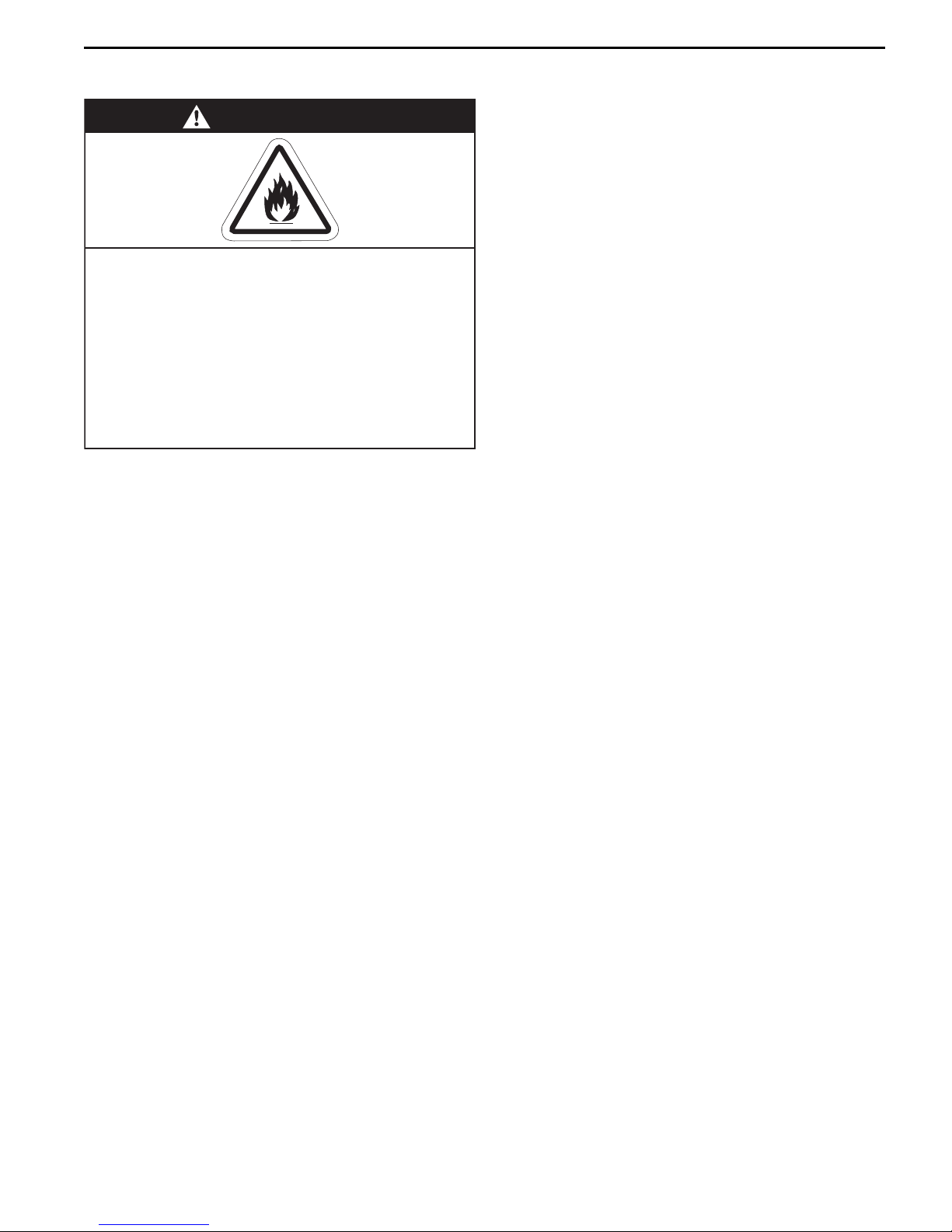
WARNING
Fire Hazard
Keep all flammable objects, liquids and
vapors the minimum required clearances to
combustibles away from heater.
Some objects will catch fire or explode when
placed close to heater.
Failure to follow these instructions can result
in death, injury or property damage.
Clearances are the required distances that
combustible objects must be away from the heater
to prevent a fire hazard. Combustibles are materials
that may catch on fire and include common items
such as wood, paper, rubber, fabric, etc. Maintain
clearances to combustibles at all times for safety.
Clearances for all heater models are located on the
serial plate of the heater and throughout the manual.
Check the clearances on the serial plate to make
sure the product is suitable for your application and
the clearances are maintained. Read and follow the
safety guidelines below:
• Keep gasoline or other combustible material
including flammable objects, liquids, dust or
vapors away from this heater or any other
equipment.
• Do not spray aerosols in the vicinity of this
heater.
• The stated clearances to combustibles
represents a surface temperature of 90° F
(50° C) above room temperature. Building
materials with a low heat tolerance (such as
plastics, vinyl siding, canvas, tri-ply, etc.) may be
subject to degradation at lower temperatures. It
is the installer's and owner's responsibility to
assure that adjacent materials are protected
from degradation.
• Maintain clearances from heat sensitive
equipment and workstations.
• Consult local Fire Marshal, Fire Insurance
Carrier or other authorities for approval of
proposed installation when there is a possibility
SECTION 4: CLEARANCES TO COMBUSTIBLES
of exposure to combustible airborne materials or
vapors.
4.2 Clearances to Combustibles
Clearances must be as indicated on Page 8, Figure
4. If clearances to combustibles are not indicated,
then installation clearances apply.
7 of 51
Page 16
UHA LOW PROFILE UNIT HEATER INSTALLATION OPERATION AND SERVICE MANUAL
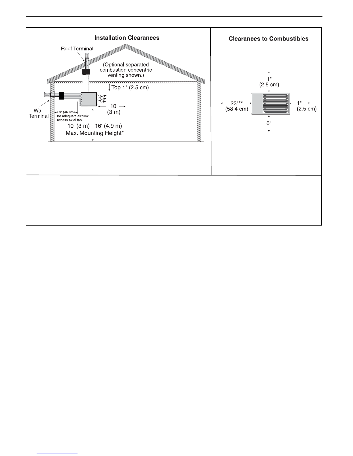
Figure 4: Installation Clearances and Clearances to Combustibles
* Recommended mounting height varies with heater input.
Heaters may be mounted at a higher level if destratification
fans are installed.
**23" (58.4 cm) minimum is
necessary for servicing.
Clearance to Vent: 2" (5 cm)
The heater must always be installed at least 6' (1.8 m) above the floor.
The vent pipe must have clearance from combustibles by 2" (5 cm).
If installed at low levels where individuals can come in contact with hot heat exchanger components,
adequate guarding must be provided.
All distances are minimum clearance requirements for service access, airflow and safety.
8 of 51
Page 17
SECTION 5: NATIONAL STANDARDS AND APPLICABLE CODES
SECTION 5: NATIONAL STANDARDS AND APPLICABLE CODES
5.1 Gas Codes
The type of gas appearing on the serial plate
must be the type of gas used. Installation must
comply with national and local codes and
requirements of the local gas company.
United States: Refer to NFPA 54/ ANSI Z223.1
- latest revision, National Fuel Gas Code.
Canada: Refer to CSA B149.1 Natural Gas and
Propane Installation Code.
5.2 Aircraft Hangars
Installation in aircraft hangars must be in
accordance with the following codes:
United States: Refer to Standard for Aircraft
Hangars, NFPA 409 - latest revision.
Canada: Refer to Natural Gas and Propane
Installation Code, Standard CSA B149.1 - latest
revision.
5.3 Parking Structures and Repair Garages
Installation in garages must be in accordance
with the following codes:
5.5 Venting
The venting must be installed in accordance
with the requirements within this manual and
the following codes:
United States: Refer to NFPA 54/ANSI Z223.1 latest revision, National Fuel Gas Code.
Canada: Refer to CSA B149.1 Natural Gas and
Propane Installation Code.
5.6 High Altitude
These heaters are approved (without
modifications) for installations up to 2000' (610
m) in US and Canada. Heaters installed above
2000' (610 m) must be de-rated. For
installations above 2000' (610 m) in US,
consult factory for information on burner derating. For installations from 2000' (610 m) to
4500' (1370 m) in Canada, high altitude
conversion kits are available. Heaters installed
over 4500' (1370 m) in Canada are not
approved and must be approved by the local or
provincial authority.
United States: Refer to Standard for Parking
Structures, NFPA 88A - latest revision or the
Code for Motor Fuel Dispensing Facilities and
Repair Garages, NFPA 30A - latest revision.
Canada: Refer to Natural Gas and Propane
Installation Code, Standard CSA B149.1 latest revision.
5.4 Electrical
The heater must be electrically grounded in
accordance with the following codes:
United States: Refer to National Electrical
®
Code
, NFPA 70 - latest revision. Wiring must
conform to the most current National Electrical
®
Code
, local ordinances and any special
diagrams furnished.
Canada: Refer to Canadian Electrical Code,
CSA C22.1 Part 1 - latest revision.
9 of 51
Page 18
UHA LOW PROFILE UNIT HEATER INSTALLATION OPERATION AND SERVICE MANUAL
SECTION 6: HEATER INSTALLATION
6.1 General
Heaters are designed for installation above 6'
(1.8 m). These heaters must be installed within the
heated space. Duct delivery systems are not
permitted with axial fan units. When handling or
supporting the heater from below, ensure that the
weight is taken at the support points.
The gas or electrical supply lines must not be used
to support the heater.
Do not locate the gas or electrical supply lines
directly over the path of the flue products from the
heater.
The heater must be installed in a location that is
readily accessible for servicing.
The heater must be installed in accordance with
clearances to combustibles as indicated on the wall
tag and this manual.
6.2 Shelf Mounting and Suspension
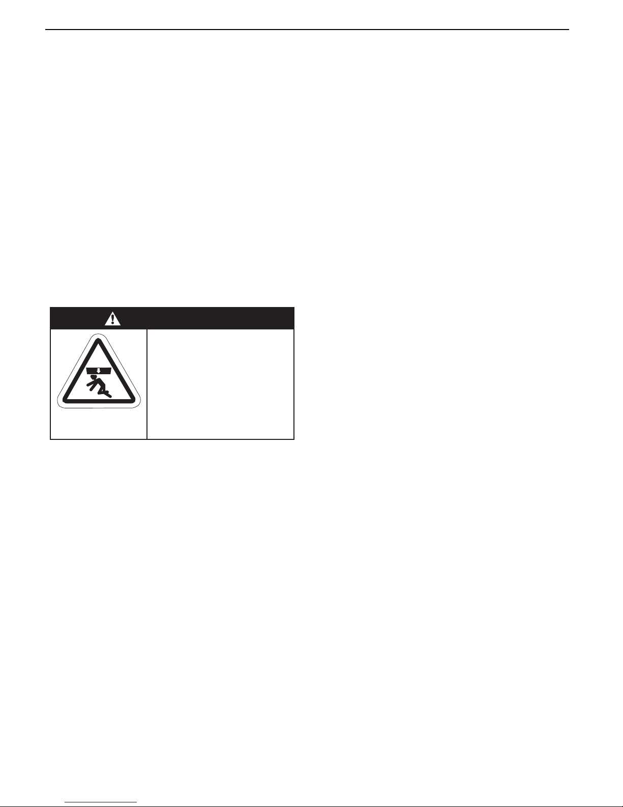
WARNING
Crush Hazard
Use 3/8" threaded rod
minimum.
Failure to follow these
instructions can result in
death, injury or property
damage.
For typical suspension, See Page 11, Figure 5.
For typical shelf mounting on existing shelf, See
Page 11, Figure 6.
6.3 Wall Mounting
For typical suspension, See Page 12, Figure 7. Wall
mounted heaters blowing parallel to the wall can
only be installed with the service door away from the
wall.
The wall mounting brackets must be attached to a
suitable wall using all mounting holes. Screw sizes
less than 3/8" may not be used. In order for the wall
mounting brackets to adequately carry the weight of
the heater, it must be installed according to best
building practices.
10 of 51
Page 19
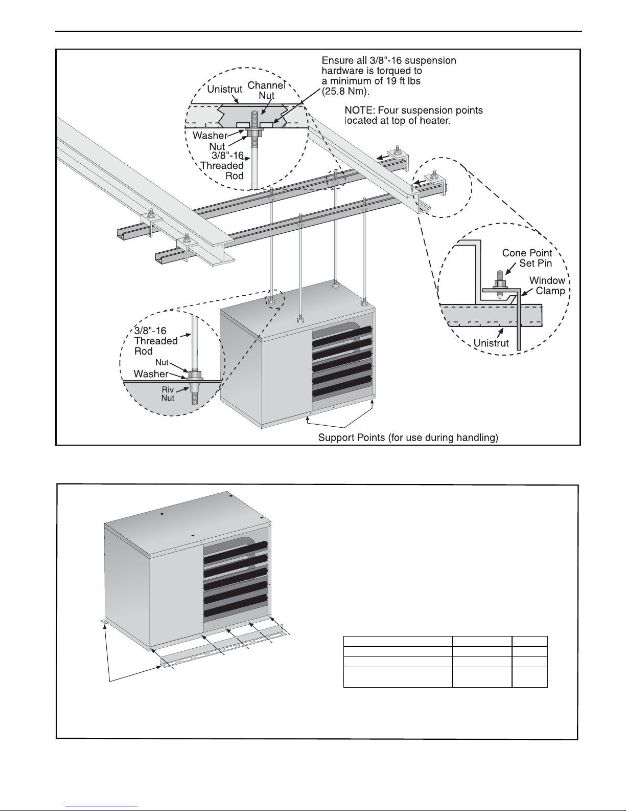
Figure 5: Suspension Methods
SECTION 6: HEATER INSTALLATION
Figure 6: Shelf-Mounting Methods
Shelf Mounting
Brackets
Existing cabinet screws must be re-used.
Description Part Number Qty.
Shelf Mounting Bracket Kit 12011000K 1
Shelf Mounting Bracket 111115 1 0 2
Screw #10 x 1/2"
Type AB Phil HWH Z
94311008 2
11 of 51
Page 20
UHA LOW PROFILE UNIT HEATER INSTALLATION OPERATION AND SERVICE MANUAL
Figure 7: Wall Shelf Mounting and Suspension
Description Part Number Qty.
Wall Shelf Mounting Bracket Kit 12011002K 1
Wall Suspension Mounting Bracket Kit 12011001K 1
Shelf Mounting Bracket Kit 12011000K 1
Description Part Number Qty.
Wall Suspension Mounting Bracket Kit 12011001K 1
Wall Mounting Bracket Arm Left 111WALL1L 1
Wall Mounting Bracket Arm Right 111WALL1R 1
Wall Mounting Bracket Vertical 111WALL2 2
Wall Mounting Bracket Diagonal 111WALL3 2
5/16" x 3 1/2" Bolt 97213925 6
5/16" Lock Nut with Nylon Insert 92114000 6
5/16" Flat Washer 95211600 6
5/16" Lockwasher 96411600 6
Hardware provided to construct mounting bracket assembly only.
12 of 51
Page 21

Figure 8: Vertical Louvers
Remove horizontal
louvers.
SECTION 6: HEATER INSTALLATION
Install vertical
louvers brackets
(top and bottom)
with supplied
screws.
Push in
louver and compress
spring to remove
(opposite end first)
Description Part Number Qty.
Vertical Louver Kit UHA[X][S] 30 &
UHA[X][S] 45
Vertical Louver Bracket 111119 0 3 2
#10 Screw 94311008 4
UHA[X][S] 30 - 45 Vertical Louvers 11111901 5
Louver Spring 90901200 2
Instruction Sheet 91040036 1
Description Part Number Qty.
Vertical Louver Kit UHA[X][S] 100 &
UHA[X][S] 125
Vertical Louver Bracket 111119 0 3 2
#10 Screw 94311008 4
UHA[X][S] 100 - 125 Vertical Louvers 111119 02 5
Instruction Sheet 91040036 1
12011003K 1
12011004K 1
Description Part Number Qty.
Vertical Louver Kit UHA[X][S] 60 &
UHA[X][S] 75
Vertical Louver Bracket 11111 90 3 2
#10 Screw 94311008 4
Instruction Sheet 91040036 1
For models UHA[X][S] 60 and UHA[X][S] 75, horizontal louvers are re-used.
Install vertical
louvers and springs
into brackets
with springs at top.
12011005K 1
13 of 51
Page 22
UHA LOW PROFILE UNIT HEATER INSTALLATION OPERATION AND SERVICE MANUAL
SECTION 7: VENTING
WARNING
Carbon Monoxide Hazard
Heaters must be vented
outdoors.
Heaters must be installed
according to the
installation manual.
Failure to follow these
instructions can result in
death or injury.
7.2.1 United States Requirements
Vent must terminate at least 3' (.9 m) above any
forced air inlet located within 10' (3.1 m).
Vent must terminate at least 4' (1.2 m) below,
4' (1.2 m) horizontally from, or 1' (.3 m) above any
door, operable window, or gravity air inlet into any
building.
NFPA 54/ANSI Z223.1 - latest revision, National
Fuel Gas Code specifies a 4' (1.2 m) horizontal vent
terminal clearance from gas and electric meters,
regulators and relief equipment.
7.1 Changing Vent and Air Intake Orientation
The heater is sold with rear horizontal vent and air
intake connections as standard (only separated
combustion models have air intake connection). If
vertical vent and air intake connections are required,
follow the instructions on Page 46, Section 15.6.
7.2 Venting
This heater must be vented in accordance with the
rules contained in this manual and with the following
national codes and any state, provincial or local
codes which may apply: United States: Refer to
NFPA 54/ANSI Z223.1 - latest revision, National
Fuel Gas Code; Canada: Refer to CSA B149.1
Natural Gas and Propane Installation Code.
Any portion of vent pipe passing through a
combustible wall must have a listed thimble to
conform with the above codes.
The bottom of the vent or air intake terminal shall not
be located less than 1' (.3 m) above grade level.
The vent shall not terminate less than 7' (2.1 m)
above grade where located adjacent to public
walkways.
Vent terminal must be installed at a height sufficient
to prevent blockage by snow and building materials
protected from degradation by flue gasses.
Vent terminal must be beyond any combustible
overhang.
Secure all joints with corrosion resistant #8 x 3/8"
sheet metal screws.
For single wall venting, pressure sensitive aluminum
tape or silicone sealant must be used to seal all
joints.
Aluminum tape shall have a minimum temperature
rating of 400° F (204° C) and meet SMACNA AFTS100-73 standards. High temperature silicone
sealant must have a minimum temperature rating of
480° F (250° C).
7.2.2 Canadian Requirements
The vent shall not terminate within 6' (1.8 m) of a
mechanical air supply inlet to any building.
The vent shall not terminate within 3' (.9 m) of a
window or door that can be opened in any building,
any non-mechanical air supply inlet to any building,
or of the combustion air inlet of any other piece of
equipment.
7.3 Vent Installation
Maintain clearances to combustibles at all times
for safety. Clearances are the required distances
that combustible objects must be away from the
heater to prevent serious fire hazard. See Page 8,
Figure 4. For vented units, the vent must terminate
outside of the building.
Vents must be fully sealed and correctly sized for
the model. If the vent passes through a wall or
ceiling of combustible material, it must be enclosed
by a listed thimble and be separated from the
thimble by at least a 2" (5 cm) air gap.
For separated combustion models, vents and air
intakes must be a fully sealed system and correctly
sized for the model. Vent should be assembled as
detailed on Page 17, Figure 9 through Page 20,
Figure 14. The joints between the vent terminal and
the roof or wall must be properly sealed.
Vents and air intakes must be adequately
supported so that the heater does not bear the
weight of the pipes.
For vent termination See Page 17, Figure 9 through
Page 20, Figure 14.
7.3.1 Standard Vented Heaters
(Models UHA[X] 30 - 125)
The vent must be fitted with a low resistance
terminal. See Page 17, Figure 9 through Page 18,
Figure 11. Standard vented heaters do not allow
outdoor air intake for combustion air.
14 of 51
Page 23

SECTION 7: VENTING
7.3.2 Separated Combustion Heaters
(Models UHA[X]S 30 - 125)
The heaters are designed to be installed as
separated combustion heaters. The vent and air
intake are run as separate pipes to the wall or roof
terminals. See Page 19, Figure 12. As an option, the
vent and air intake are run as separate pipes to a
concentric vent box and a concentric vent/air intake
pipe penetrates the wall or roof. See Page 19,
Figure 13 and Page 20, Figure 14.
For seperated combustion installation, the vent and
air intake must be fitted with an individual and
correctly sized sealed system and the vent and air
intake must terminate at approved wall and roof
terminals.
Seperated combustion units may not be common
vented.
7.4 Horizontal Venting
Horizontally vented heaters must be individually
vented, no common venting.
Vent pipe must be sloped ¼" (.6 cm) downward for
every 1' (.3 m) away from heater. For vent lengths
greater than 10' (3.0 m), condensation will form.
Insulation is recommended and condensation drains
may be desired. For vents pitched up towards the
vent terminal, place the condensation drain within
10' (3.0 m) of the heater.
In noncombustible walls only, vent terminal
(P/N 02537801-1P) may be used.
For 4'' (10 cm) vents in either combustible or
noncombustible walls, use vent terminal (P/N
90502100) or equivalent insulated vent terminal.
Follow the manufacturer's instructions for proper
installation.
Instead of an insulated vent terminal, a listed thimble
with 2" (5 cm) air gap may be used with a 4" (10 cm)
vent cap (P/N 90502102).
In the State of Massachusetts, the following
regulations apply to horizontally-vented heaters
certified for installation in structures used in whole or
in part for residential purposes (UHA 30-75 only)
and where the side wall exhaust vent termination is
less than seven (7) feet above finished grade in the
area of the venting, including but not limited to decks
and porches:
Installation of Carbon Monoxide Detectors: At the
time of installation of the side wall horizontal vented
gas fueled equipment, the installing plumber or
gasfitter shall observe that a hard wired carbon
monoxide detector with an alarm and battery backup is installed on the floor level where the gas
equipment is to be installed. In addition, the
installing plumber or gasfitter shall observe that a
battery operated or hard wired carbon monoxide
detector with an alarm is installed on each additional
level of the dwelling, building or structure served by
the side wall horizontal vented gas fueled
equipment. It shall be the responsibility of the
property owner to secure the services of qualified
licensed professionals for the installation of hard
wired carbon monoxide detectors
• In the event that the side wall horizontally vented
gas fueled equipment is installed in a crawl
space or an attic, the hard wired carbon
monoxide detector with alarm and battery backup may be installed on the next adjacent floor
level.
• In the event that the requirements of this
subdivision can not be met at the time of
completion of installation, the owner shall have a
period of thirty (30) days to comply with the
above requirements; provided, however, that
during said thirty (30) day period, a battery
operated carbon monoxide detector with an
alarm shall be installed.
Approved Carbon Monoxide Detectors: Each carbon
monoxide detector as required in accordance with
the above provisions shall comply with NFPA 720
and be ANSI/UL 2034 listed and IAS certified.
Signage: A metal or plastic identification plate shall
be permanently mounted to the exterior of the
building at a minimum height of eight (8) feet above
grade directly in line with the exhaust vent terminal
for the horizontally vented gas fueled heating piece
or equipment. The sign shall read, in print size no
less than one-half (1/2) inch in size, “GAS VENT
DIRECTLY BELOW. KEEP CLEAR OF ALL
OBSTRUCTIONS”.
Inspection: The state or local gas inspector of the
side wall horizontally vented gas fueled equipment
shall not approve the installation unless, upon
inspection, the inspector observes carbon monoxide
detectors and signage installed in accordance with
the provisions of 248 CMR 5.08(2)(a)1 through 4.
7.5 Vertical Venting
Vertically vented standard-vented heaters can be
common vented (up to 4 heaters).
For vent lengths greater than 10' (3.0 m),
condensation will form. Insulation is recommended
and condensation drains may be desired. Venting
through the top of the heater cabinet is not
recommended if vent lengths are longer than 10'
(3 m) UHA[X][S] 30-75 only. In this case, vent from
15 of 51
Page 24
UHA LOW PROFILE UNIT HEATER INSTALLATION OPERATION AND SERVICE MANUAL
the rear of the heater cabinet then run the vent
vertically and use a condensate drain at the bottom
of the vertical vent.
Vent pipe must be sloped 1/4'' (.6 cm) for every 1' (.3
m).
For 4'' (10 cm) common vent, an approved vent cap
(P/N 90502102) must be used.
For 6'' (15 cm) common vent, an approved vent cap
(P/N 90502103) must be used.
For common vertical venting of more than two
heaters, See Page 18, Figure 11.
A vent shall not extend less than 2' (.6 m) above the
highest point where it passes through a flat roof of a
building.
7.6 Length Requirements
If using vent lengths greater than 10' (3.0 m),
condensation will form in the vent pipe. Insulation
and additional sealing measures (high temperature
silicone at all seams) are required.
The entire vent should be insulated with foil faced
fiberglass insulation (1/2" thick, 1-1/2# density
minimum).
7.6.1 Maximum Vent Lengths Table
Model UHA[X][S]30 - 125 # of Elbows
30 ft (9.1 m) 1
25 ft (7.6 m) 2
20 ft (6.1 m) 3
15 ft (4.5 m) 4
10 ft (3.0 m) 5
7.7 Vent Material
Vent material may be single wall 26 ga. (minimum)
galvanized steel or equal thickness stainless steel.
Completely seal all joints, refer to Page 14, Section
7.3.
If penetrating a combustible wall or roof, a listed
thimble with 2" (5 cm) clearance must be used.
Where local codes permit, a single section of type
B-1 vent material may be used at the roof or wall
penetration instead of a thimble. Ensure vent
manufacturer's clearance from vent material is
maintained. Seal annular space of the type B-1 vent
as well as all joints in the remaining vent.
7.8 Replacing an Existing Heater in a Venting
System
When replacing an existing heater in a venting
system, the venting system may not be properly
sized to vent the new heater. The following steps
must be followed with each piece of equipment
connected to the venting system placed in
operation, while any other equipment connected to
the venting system are not in operation.
1. Seal any unused openings in the venting
system.
2. Inspect the venting system for proper size and
horizontal pitch, as required by the NFPA 54/
ANSI Z223.1 - latest revision, National Fuel
Gas Code (US) or Standard CSA B149.1
Natural Gas and Propane Installation Code
(Canada) and these instructions. Determine
that there is no blockage or restriction, leakage,
corrosion and other deficiencies which could
cause an unsafe condition.
3. Close all building doors and windows and all
doors between the space in which the piece(s)
of equipment connected to the venting system
are located and other spaces of the building.
Turn on clothes dryers and any exhaust fans,
such as range hoods and bathroom exhausts
so that they shall operate at maximum speed.
Do not operate a summer exhaust fan. Close
fireplace dampers.
4. Follow the lighting instructions. Place the
equipment being inspected in operation. Adjust
thermostat so that the equipment will operate
continuously.
5. For any equipment having a draft hood, test for
draft hood equipment spillage at the draft hood
relief opening after five minutes of main burner
operation. Use the flame of a match or candle.
6. After it has been determined that each piece(s)
of equipment connected to the venting system
properly vents when tested as outlined above,
return doors, windows, exhaust fans, fireplace
dampers and any other gas-burning piece(s) of
equipment to their previous conditions of use.
7. If improper venting is observed during any of
the above tests, the venting system must be
corrected by a contractor qualified in the
installation and service of gas-fired equipment
or your local gas supplier. If the venting must be
resized, use appropriate tables in (US)
Appendix G of NFPA 54/ANSI Z223.1 - latest
revision, National Fuel Gas Code (US) or
Standard CSA B149.1 Natural Gas and
Propane Installation Code (Canada) to
determine minimum size. All vent corrections
must be in accordance with the appropriate
local codes and the NFPA 54/ANSI Z223.1 latest revision, National Fuel Gas Code (US) or
Standard CSA B149.1 Natural Gas and
Propane Installation Code (Canada).
16 of 51
Page 25
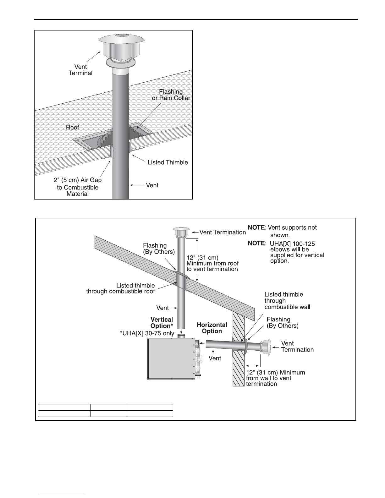
Figure 9: Vent and Roof Detail
SECTION 7: VENTING
Figure 10: Standard Vented Heater - Vertical and Horizontal Vent Termination
Model Vent Diameter Part Number
UHA[X] 30 - 125 4" (10 cm) 90502102
17 of 51
Page 26
UHA LOW PROFILE UNIT HEATER INSTALLATION OPERATION AND SERVICE MANUAL
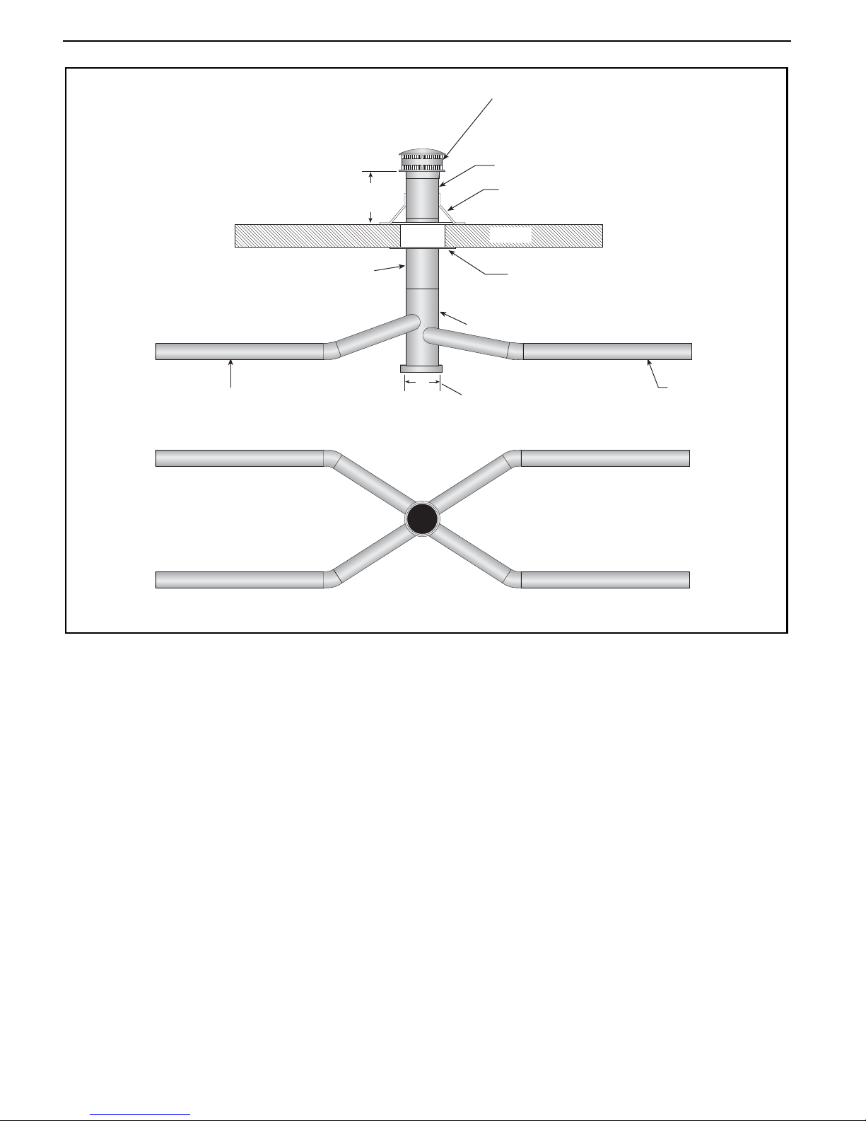
Figure 11: Standard Vented Heater - Common Vertical Vent Termination
Type "B" vent cap
(7" [18 cm] or 8" [20 cm]) may be
SIDE VIEW
2'(.6 m)
Minimum
used. (These are not available
from the manufacurer.)
Type "B" Vent Pipe
Roof
Flashing
Roof
The last section of vent pipe passing
through the roof or wall may be Type
"B" vent pipe. All other vent materials
in the building must be single wall
vent pipe.
4" (10 cm)
Single Wall Pipe
TOP VIEW
"D"
Approved
Thimble
(If Applicable)
Single Wall Pipe
"D" Area must equal sum
of open area of
individual vents.
4" (10 cm)
Single Wall Pipe
Requirements:
• Maximum of four heaters can be commonly vented through the roof.
• Heaters must be of the same BTU output.
• Heaters must be controlled by a common thermostat.
• Connections to a common stack must be positioned to avoid opposition between streams of
combustion gas.
18 of 51
Page 27
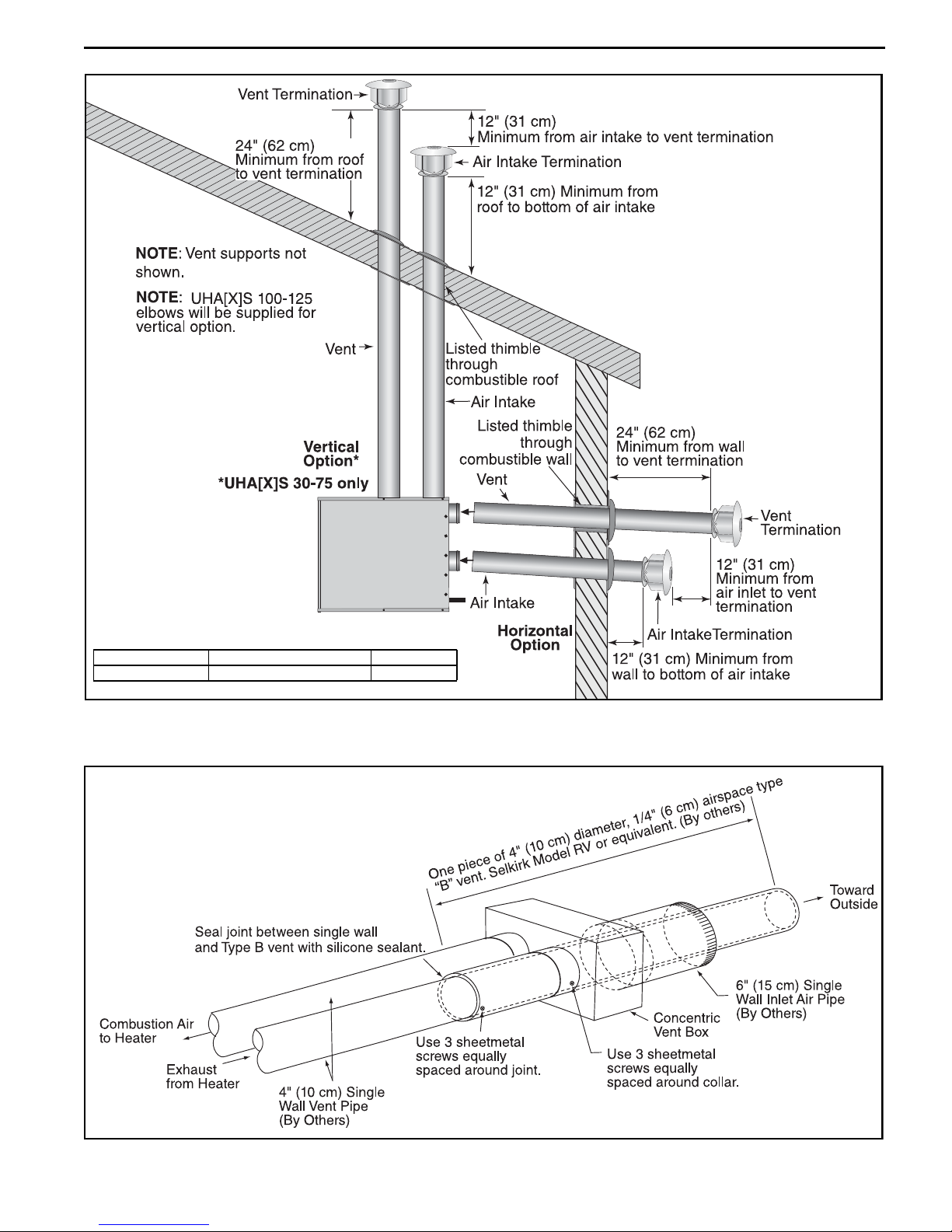
Figure 12: Separated Combustion Heater - Vertical and Horizontal Vent Termination
SECTION 7: VENTING
Model Air Intake & Vent Diameter Part Number
UHA[X]S 30 - 125 4" (10 cm) 90502102
Figure 13: Concentric Vent Box
19 of 51
Page 28
UHA LOW PROFILE UNIT HEATER INSTALLATION OPERATION AND SERVICE MANUAL
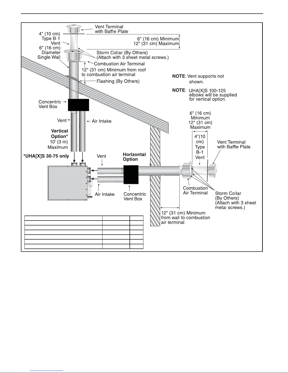
Figure 14: Concentric Vertical and Horizontal Vent Termination - Separated Combustion Heater
Description Part Number Qty.
Concentric Vent Kit UHVK1 1
Concentric Vent Box Top & Side Assembly 90504113 1
Concentric Vent Box Bottom Assembly 90504112 1
Screw #6 x 3/8 Self Drilling 91119100 14
4" (10 cm) Vent Terminal with Baffle Plate 90502102R 1
6" (16 cm) Combustion Air Terminal 90502103 1
20 of 51
Page 29
SECTION 8: AIR SUPPLY
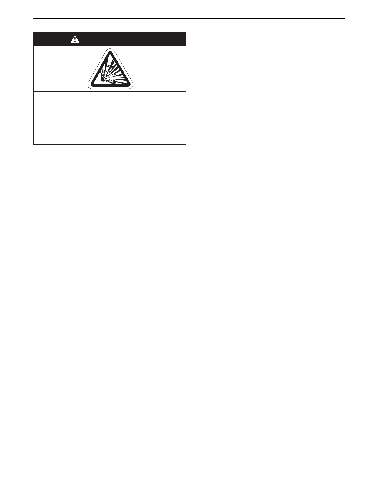
WARNING
Explosion Hazard
Equipment must have access to
uncontaminated air at all times.
Failure to follow these instructions can result
in death, injury or property damage.
8.1 Separated Combustion Installation
When installed as a separated combustion heater
(UHA[X]S), the air for combustion is drawn in from
outside the building. It is important to ensure that
there is adequate space around heater to provide air
for the axial air distribution fan.
SECTION 8: AIR SUPPLY
8.2 Building Ventilation
Where ventilation is required, air must be taken from
an outside point where it is not likely to be
contaminated or obstructed.
8.3 Outside Combustion Air Supply
If outside combustion air supply is required,
separated combustion model (UHA[X]S) heaters
must be used.
Caution: If the building has a slight negative
pressure or corrosive contaminants such as
halogenated hydrocarbons are present in the air, an
outside combustion air supply to the heater is
required. Seal all combustion air pipe joints.
The outside air terminal must not be more than 1'
(31 cm) above the vent terminal.
8.3.1 Length Requirements
Follow the constraints listed on Page 16, Section 7.6.
21 of 51
Page 30
UHA LOW PROFILE UNIT HEATER INSTALLATION OPERATION AND SERVICE MANUAL
SECTION 9: GAS PIPING
Canada: Rubber type 1 gas hose (Canadian
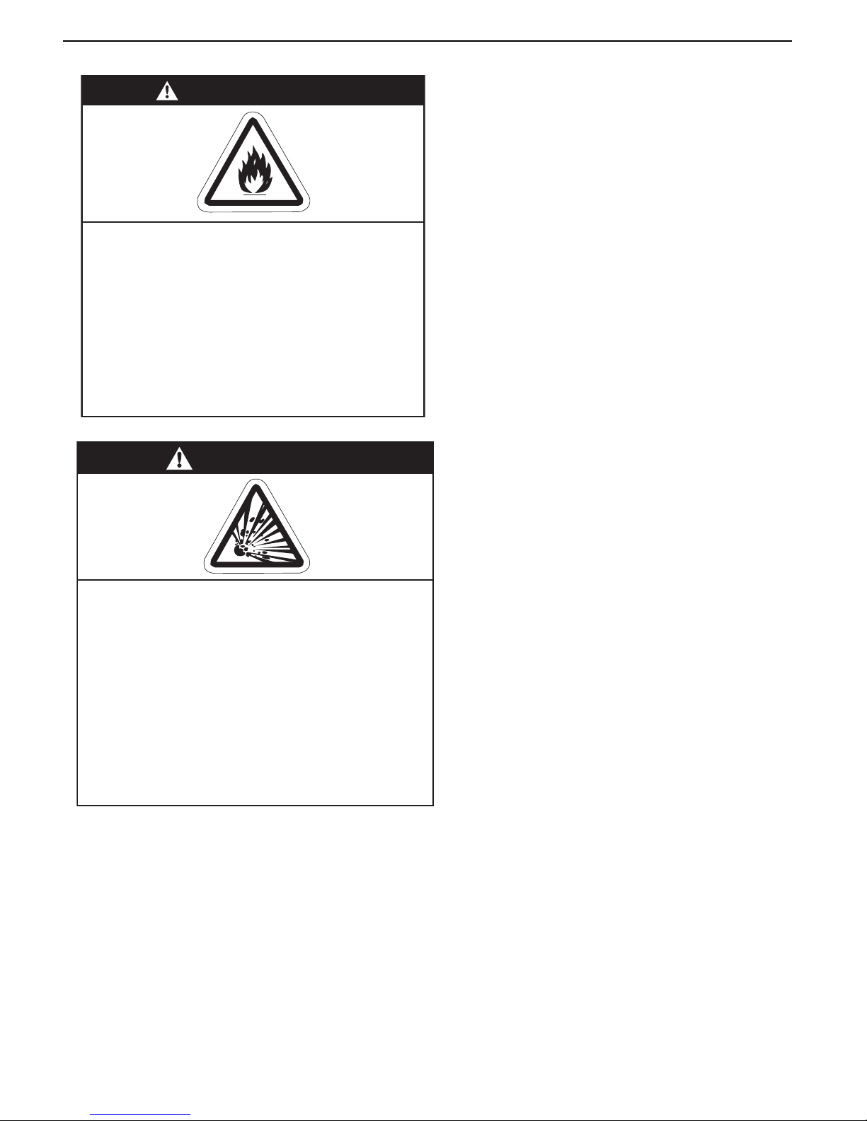
WARNING
Fire Hazard
Connect gas supply according to Figure 15.
Do not use gas supply pipe and electrical
connections to support heater’s weight.
Gas can leak if not installed properly.
Failure to follow these instructions can
result in death, injury or property damage.
WARNING
Explosion Hazard
Leak test all components of gas piping
before operation.
Gas can leak if piping is not installed
properly.
Do not high pressure test gas piping with
heater connected.
Failure to follow these instructions can result
in death, injury or property damage.
A gas meter is connected to the service pipe by the
gas supply company. An existing meter should be
checked, preferably by the company, to ensure that
the meter is adequate for the rate of gas supply
required.
Installation pipes must be fitted in accordance with
local and national codes. Pipes of smaller size than
the heater inlet gas connection should not be used.
Gas lines must meet applicable codes:
United States: Flexible stainless steel gas hose
(US models) is certified per the standard for
connectors for gas applications. ANSI Z21.21/CSA
6.10 – latest revision.
models) is certified as being in compliance with the
standard for elastomeric compostite hose and hose
couplings for conducting propane and natural gas,
CAN/CGA 8.1 – latest revision.
9.1 Connections
Connect the heater to the gas supply ensuring that
the final connections are as follows:
• Gas supply pipe work is run in medium or heavy
gauge tubing in compliance with local and
national codes.
• Meter and service must be large enough to
handle all the burners being installed plus any
other connected load. The gas pipe which feeds
the system must be large enough to supply the
required gas with a maximum pressure drop of
1/2 in wc. When gas piping is not included in the
layout drawing, contact the local gas supplier.
• An isolating valve and union connection should
be used and fitted into the supply adjacent to the
heater.
• A minimum 1/8" NPT plugged tapping
accessible for test connection must be installed
immediately upstream of the gas supply
connection to the heater.
• For suspended heaters, an approved metal
flexible connection between the isolating valve
and the heater may be used. To reduce
pressure loss, use one pipe size larger than
the heater gas connection.
IMPORTANT - The complete installation must be
purged and tested for gas soundness in accordance
with local and national codes.
Caution: Do not high pressure (in excess of 1/2 psi
[14 in wc]) test the gas piping with the burner
connected. Close manual shut-off valve during any
pressure testing equal to or less than 1/2 psi (14 in
wc).
Check the pipe and tubing ends for leaks before
placing heating equipment into service. When
checking for gas leaks, use a soap and water
solution; never use an open flame.
22 of 51
Page 31
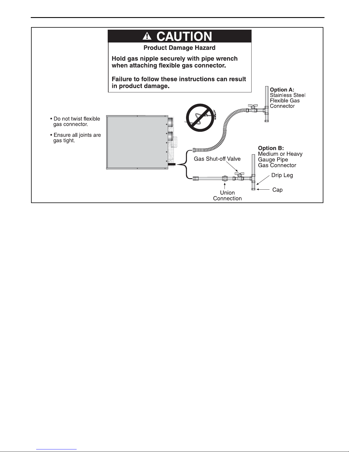
Figure 15: Gas Connection
SECTION 9: GAS PIPING
23 of 51
Page 32
UHA LOW PROFILE UNIT HEATER INSTALLATION OPERATION AND SERVICE MANUAL
SECTION 10: WIRING
Heater must be wired and electrically grounded in
DANGER
accordance with local codes. In the absence of local
codes in accordance with: United States: refer to
National Electrical Code
Canada: refer to Canadian Electrical Code CSA
C22.1 Part I - latest revision.
10.1 Positioning Thermostats
Electrical Shock Hazard
Disconnect electric before service.
A room thermostat should be mounted on a
vibration-free wall or column at a height of
approximately 5' (1.5 m) from the floor to measure
More than one disconnect switch may be
required to disconnect electric from
equipment.
Equipment must be properly grounded.
the ambient temperature. It should be clear of both
cold drafts and the direct path of warm air from the
heater.
Avoid mounting thermostat on outside walls or in
areas directly exposed to radiant heat or sunlight.
Failure to follow these instructions can result
in death or electrical shock.
Install wall tag in a visible location near thermostat
See Page 5, Section 2.1 for wall tag details.
®
NFPA 70 - latest revision;
All heater models require constant 120 V / 1Ø / 60
Hz power supply. Check heater serial plate for
electrical rating for proper circuit sizing. For
servicing, a disconnect switch of proper electrical
rating should be installed in the vicinity of the heater.
All heaters are equipped with thermostat
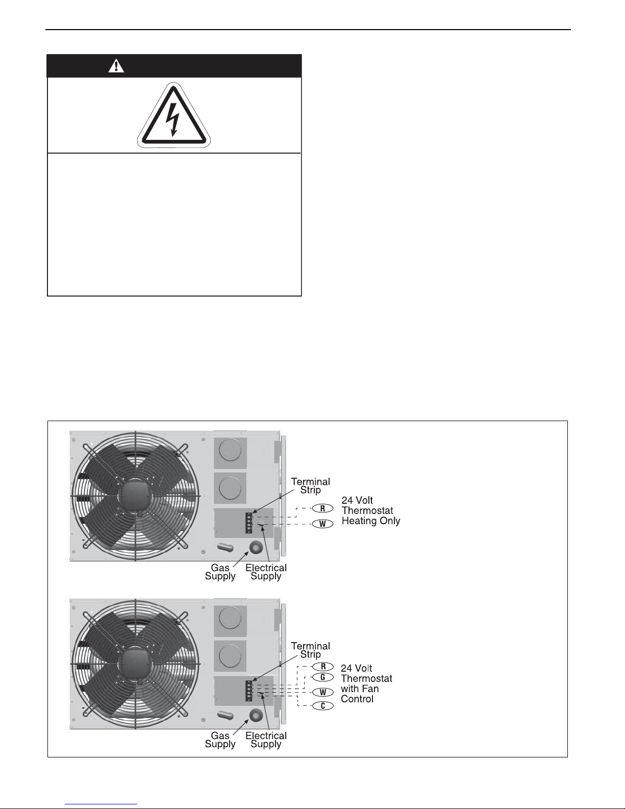
connections suitable to power a 24 V thermostat.
10.2 Low Voltage Thermostat with One Heater
10.1.1 Fan Control
The heater’s axial fan can be used during the off-
season for air circulation. A low-voltage
programmable thermostat with a fan switch (P/N
90425400) must be used.
For thermostat connection details, See Page 24,
Section 10.2.
24 of 51
Page 33
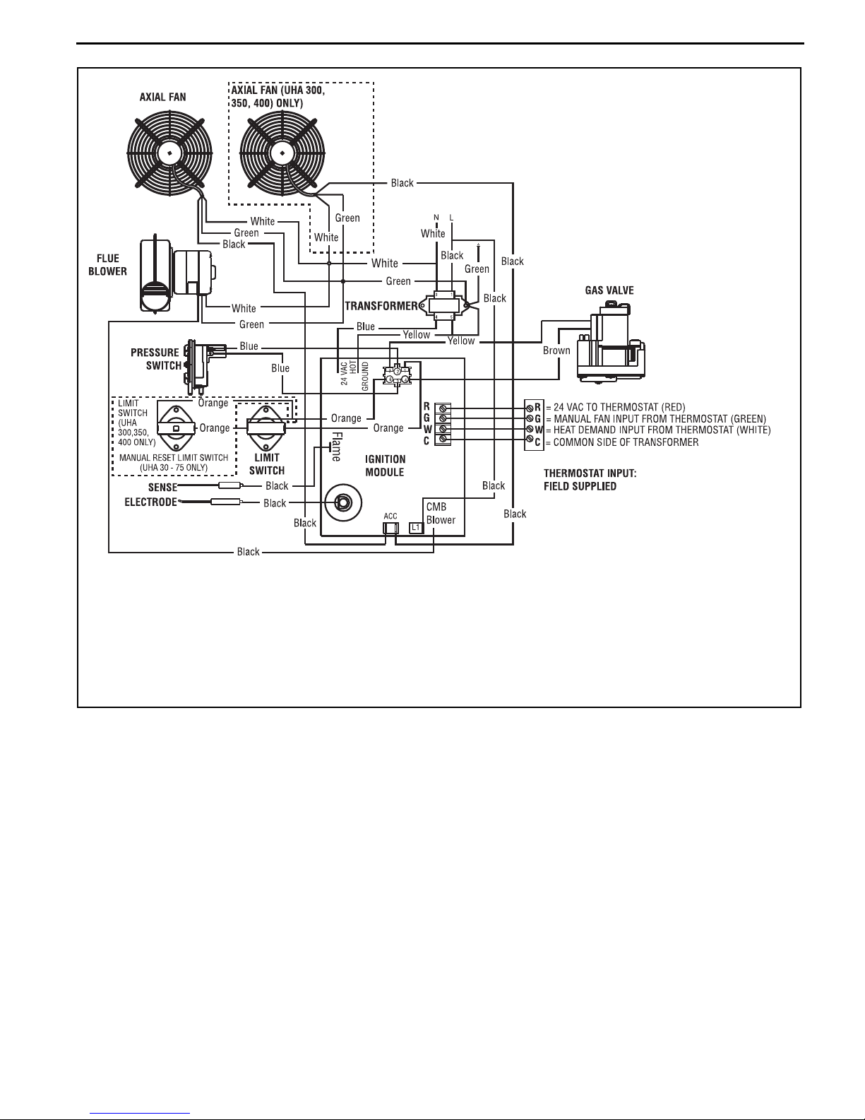
10.3 UHA[X][S] Internal Wiring Diagram
SECTION 10: WIRING
IMPORTANT:
For field wiring into service junction box, or if any of the original wire supplied with the heater
must be replaced, it must be replaced with wiring material having a temperature rating of at least 105° C
(221° F) and 600 volts. For supply connections, use No. 14 AWG or larger wires.
25 of 51
Page 34
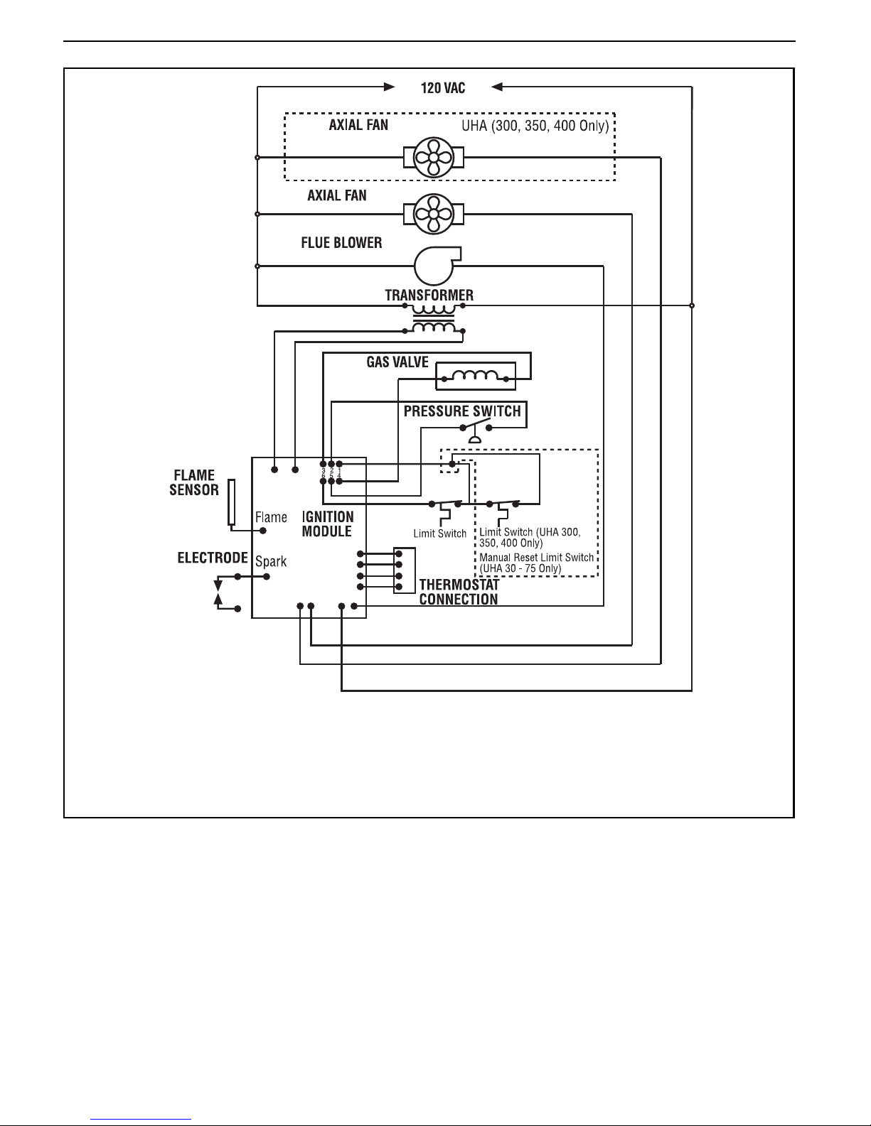
UHA LOW PROFILE UNIT HEATER INSTALLATION OPERATION AND SERVICE MANUAL
10.4 UHA[X][S] Ladder Wiring Diagram
IMPORTANT:
For field wiring into service junction box, or if any of the original wire supplied with the heater
must be replaced, it must be replaced with wiring material having a temperature rating of at least 105° C
(221° F) and 600 volts. For supply connections, use No. 14 AWG or larger wires.
26 of 51
Page 35
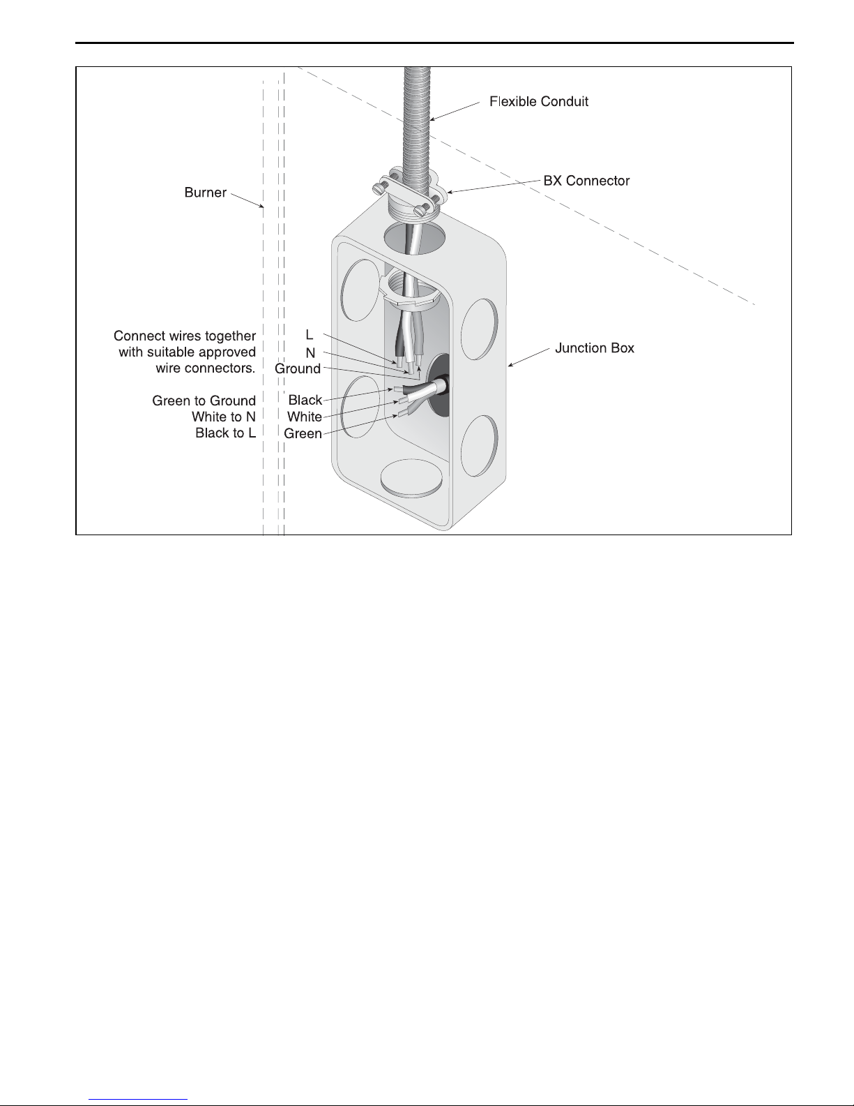
10.5 Electrical Connection to the Heater
SECTION 10: WIRING
IMPORTANT: Junction box is not provided with heater.
Conduit can also be attached directly to heater with wire junction made within the heater cabinet.
27 of 51
Page 36
UHA LOW PROFILE UNIT HEATER INSTALLATION OPERATION AND SERVICE MANUAL
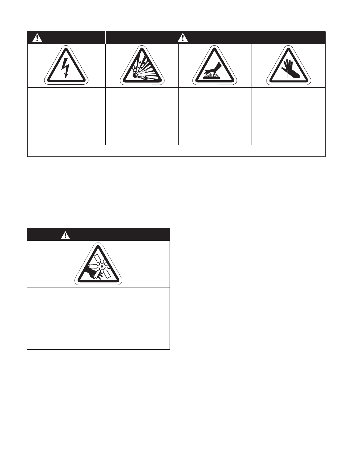
SECTION 11: OPERATION AND MAINTENANCE
DANGER
Electrical Shock Hazard
Disconnect electric
before service.
Heater must be
connected to a properly
grounded electrical
source.
Failure to follow these instructions can result in death, electric shock, injury or property damage.
Read this manual carefully before installation,
operation, or service of this equipment. All
components are accessed via the hinged door.
Opening the door exposes live electrical
connections and hot components.
Prior to any maintenance or service of the heater,
shut off, lockout and tagout the electrical disconnect
and gas valve that supplies the unit in accordance
with OSHA regulations.
Explosion Hazard
Turn off gas supply to
heater before service.
WARNING
WARNING
Burn Hazard
Allow heater to cool
before service.
Tubing may still be hot
after operation.
11.1.2 Electrical Checks
1. Check that all site wiring is connected in
accordance with the appropriate wiring diagram
on Page 25, Section 10.3.
11.1.3 Gas Supply
All aspects of the gas installation including the gas
meter must be inspected, tested for gas tightness
and purged in accordance with local and national
codes.
Ensure that the air is fully purged from the heater
inlet pipe up to the main gas valve inlet test nipple.
Cut/Pinch Hazard
Wear protective gear
during installation,
operation and service.
Edges are sharp.
Severe Injury Hazard
Turn off gas and electrical supply before
service.
Fan can start automatically at any time.
Failure to follow these instructions can
result in severe injury or product damage.
11.1 Pre-Start-Up Checks
All pre-start-up checks must be carried out before
lighting the heater.
Ensure that the heater and all controls are suitable
for the gas, pressure and electrical supply to which
they are to be connected.
11.1.1 Louvers
Where fitted, the air delivery louvers need to be set
during start-up to give the required air distribution
(optional vertical louvers).
11.1.4 Mechanical Checks
1. Check that the fan is free to run and delivery
louvers are turned to give required air
deflection.
2. Check that the flue (and air intake for separated
combustion units) is installed in accordance
with the instructions in this manual and local
regulations. See Page 14, Section 7.
11.2 Begin Start-Up
11.2.1 Before Operating the Heater
To ensure that all the controls are in safe working
order, operate the heater for the first time with the
isolating gas valve turned off and power supply
turned on.
1. Turn off the isolating gas valve.
2. Turn up the thermostat above room
temperature. The automatic ignition
sequence will now begin as described
on Page 29, Figure 16.
There will be no ignition of the burner and lockout
will occur, which proves the controls are operating
correctly.
28 of 51
Page 37
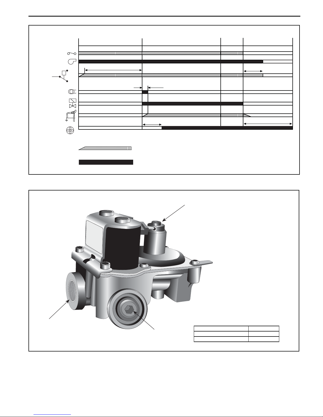
Figure 16: Automatic Burner Control Sequence
Burner Sequence for Ignition Control
START
Thermostat 24 V
SECTION 11: OPERATION AND MAINTENANCE
RUN
SHUT DOWN
Flue Blower
Pressure
Switch
Ignition Spark
Start Gas Valve
Flame Signal
Axial Fan
NO
P
C
NC
*Purge time begins at pressure switch change over.
30 Seconds Purge*
ts = 10 Seconds
30 Seconds Delay 90 Seconds Delay
Required Incoming Signals
Signals Output By Control
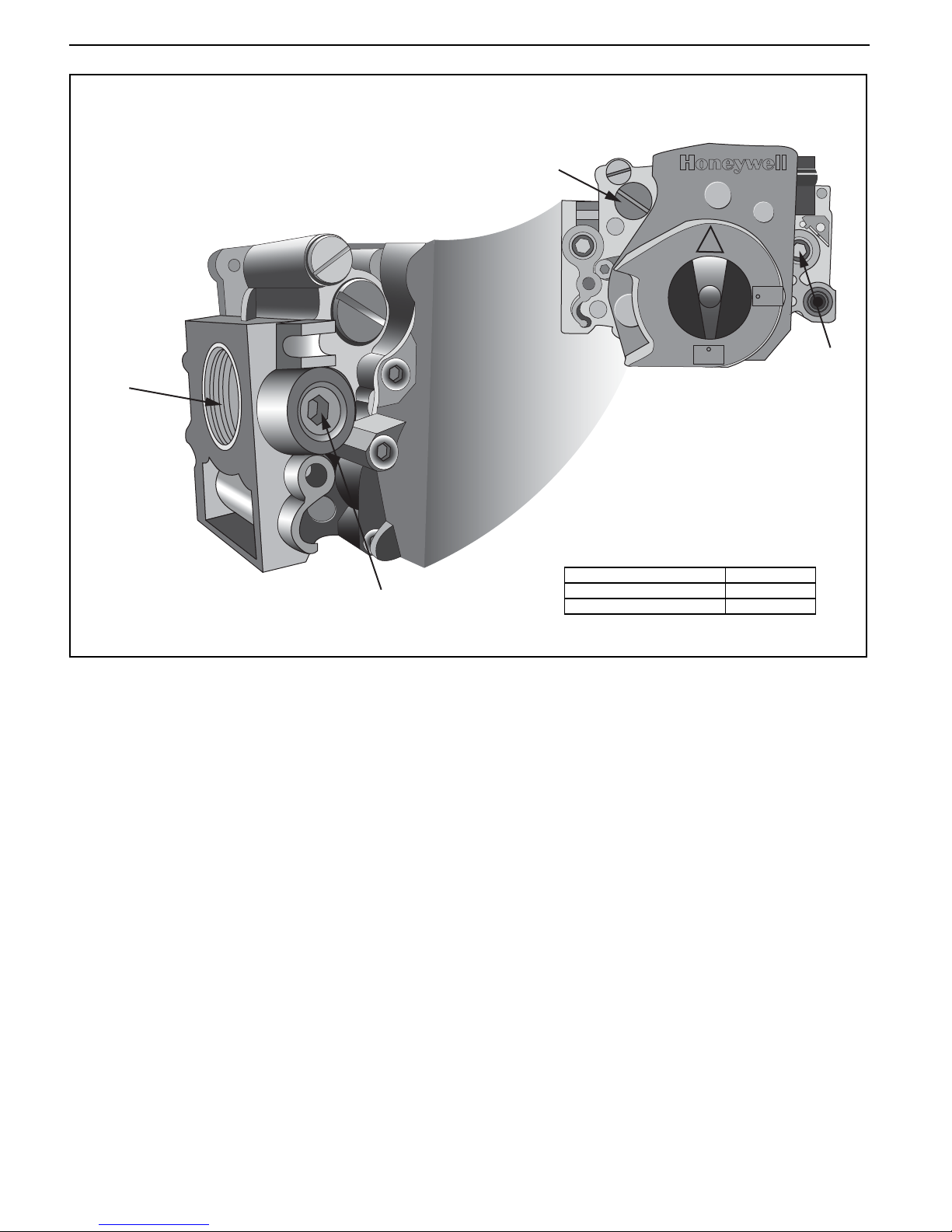
Figure 17: Gas Valve for Models UHA[X][S] 30 - 45
Pressure Regulator
30 Seconds Post Purge
If at any stage the flame fails, the control will retry
for ignition. The control has four trials for ignition
before a one hour lockout.
Gas Outlet
Outlet Pressure
Description Part Number
Gas Valve 30 - 45 NG 90034500
Gas Valve 30 - 45 LP 90034600
29 of 51
Page 38
UHA LOW PROFILE UNIT HEATER INSTALLATION OPERATION AND SERVICE MANUAL
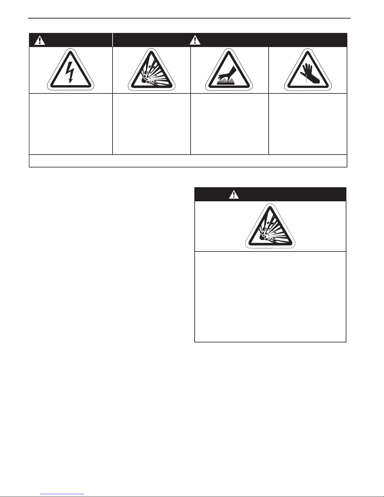
Figure 18: Gas Valve for Models UHA[X][S] 60 - 125
Regulator
TOP VIEW
Gas Inlet
END VIEW
Inlet Pressure
½PSI IN
C
ON
OFF
Description Part Number
Gas Valve 60 - 125 NG 90032505
Gas Valve 60 - 125 LP 90032506
Outlet
Pressure
11.2.2 Start-Up the Gas Valve (All Gases)
11.2.2.1 Check Burner Gas Pressure
1. Remove the plug in the outlet (burner) pressure
test point and connect a pressure tap and a
manometer.
2. With the burner firing, measure the pressure on
the manometer. To adjust the burner pressure,
remove the regulator cover from the valve and
turn the regulator adjustment screw to set the
required burner pressure as stated in the
Technical Data Table for the correct gas and
model on Page 50, Section 16.3.
NOTE: If the correct burner pressure cannot be
reached, then check the inlet pressure to the valve
with the burner firing. See Technical Data Table on
Page 50, Section 16.3 for inlet pressure
requirement.
Do not continue to adjust the regulator if the
pressure is not changing.
If the inlet pressure is too low to allow correct burner
pressure setting, then the gas inlet pressure must be
corrected before completing the start-up.
11.2.2.2 Check Gas Rate
1. After burner pressure adjustment, allow the
heater to operate for at least 15 minutes and
then re-check settings. Adjust pressure setting
if necessary.
2. Check gas flow rate at gas meter.
3. Turn off heater and electrical supply.
4. Remove the manometer and refit all covers to
the valve and tighten the screw of the outlet
pressure tap.
11.3 Pressure Switch
The pressure switch is factory pre-set for each
model and is not adjustable.
11.4 Turning Off the Heater
Set the thermostat to the "OFF" position or lowest
setting and the main burner will stop.
The fan will continue to run until it is stopped
automatically by the fan thermostat.
30 of 51
Page 39

Do not use a disconnect switch for control of
heater. Disconnect switch will turn off the fan.
Heat exchanger could be damaged. Warranty will
not cover damage to the heat exchanger if
operated improperly. Only use the disconnect
switch for turning off heater for service or during
off-season.
11.5 External Controls
External controls may include time switch, interlock
switch, room thermostat and frost thermostat.
Operate each control to ensure that they function
correctly. Set the switches (if fitted) and
thermostat(s) to the users’ requirements.
11.6 Complete Start-Up
Ensure that all covers are fitted correctly and all test
points are properly sealed.
11.7 Instruction to the User
Explain the controls of the heater to the user
including how to turn it on and off, using the controls
equipped on site.
Give this manual to the user.
Ensure that the user is shown and understands the
importance of maintaining clearances to
combustibles on Page 8, Figure 4, installer
responsibility on Page 5, Section 2 and user
instructions on Page 32, Section 12 and all
warnings defined in this manual.
SECTION 11: OPERATION AND MAINTENANCE
31 of 51
Page 40
UHA LOW PROFILE UNIT HEATER INSTALLATION OPERATION AND SERVICE MANUAL
SECTION 12: USER INSTRUCTIONS
DANGER
Electrical Shock Hazard
Disconnect electric
before service.
Heater must be
connected to a properly
grounded electrical
source.
Failure to follow these instructions can result in death, electric shock, injury or property damage.
The UHA[X][S] Series heaters are fully automatic
and operate from the external controls fitted on site.
The only user control at the heater is the Manual
Reset Limit Switch - See Page 32, Section 12.2.
See Page 44, Section 15.3 for manual reset limit
switch location inside control housing.
Explosion Hazard
Turn off gas supply to
heater before service.
WARNING
Burn Hazard
Allow heater to cool
before service.
Tubing may still be hot
after operation.
12.2 Common User Controls
12.2.1 Manual Reset Limit Switch
Cut/Pinch Hazard
Wear protective gear
during installation,
operation and service.
Edges are sharp.
WARNING
12.1 Heater Operation
When the heater has been switched on by the
thermostat installed on site, the main burner will
automatically turn on.
The burner control box will control the safe ignition
of the flame.
All heaters require a constant gas and electricity
supply which must not be interrupted during the
normal operation of this heater.
Should overheating occur, or the gas supply control
system fail to shut off the flow of gas, shut off the
manual gas valve to the utility heater before shutting
off the electrical supply.
Do not use this utility heater if any part has been
under water. Immediately call a qualified service
technician to inspect the heater and replace any gas
control which has been under water.
Explosion Hazard
Do not make more than one attempt to
restart the heater if manual reset limit switch
locks out.
The vent or heat exchanger may be blocked.
The fault must be traced and repaired.
Failure to follow these instructions can
result in death, injury or property damage.
On residentially approved models, the limit
thermostat is located inside the hinged access door
of the heater. See Page 44, Section 15.3. This
control protects against excessive heat build-up
inside the burner compartment.
32 of 51
Page 41
SECTION 12: USER INSTRUCTIONS
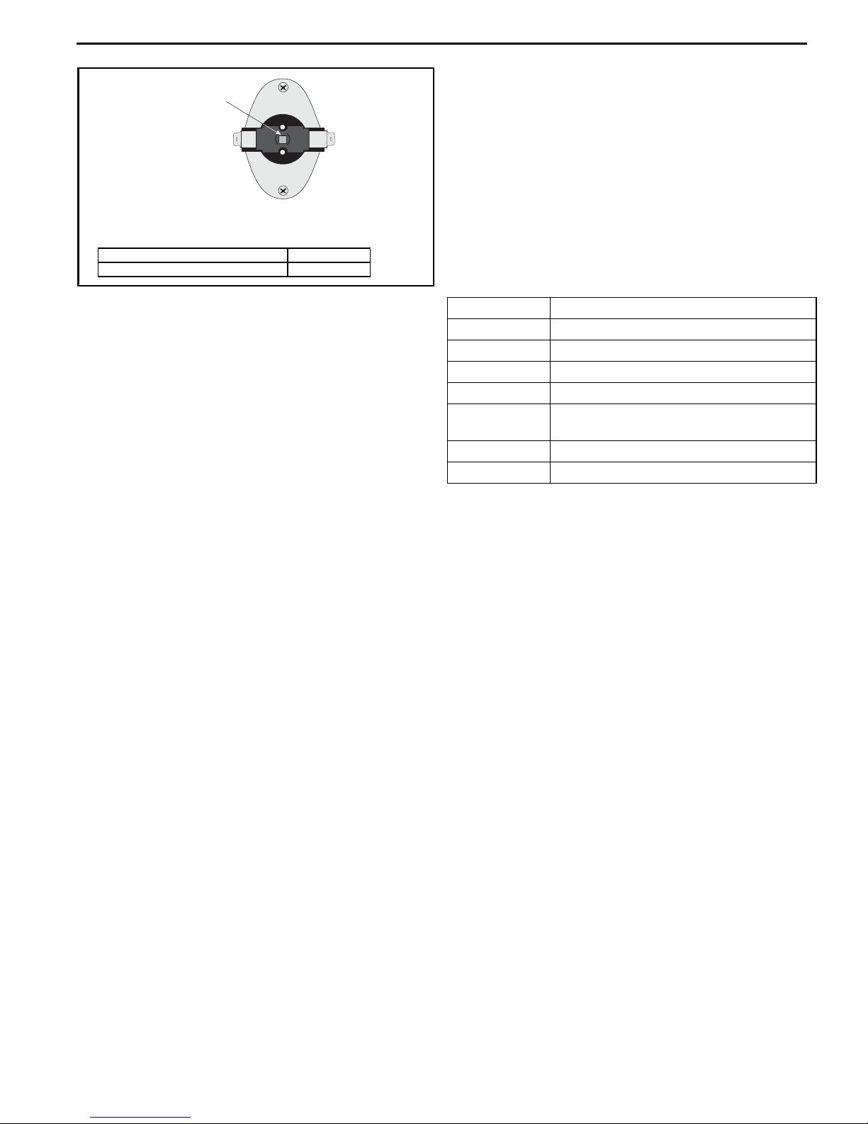
Figure 19: Manual Reset Limit Switch
Reset Button
To reset manual reset limit switch, press reset
button. NOTE: To reset, the switch must be cool.
Description Part Number
Manual Reset Limit Switch 90412106
12.3 Lighting Instructions
12.3.1 To Turn On Heater
1. Ensure that the electrical and gas supplies to
the heater are on. Check that the on site
controls are "ON".
IMPORTANT: The thermostat setting must be above
the ambient temperature for the heater to operate.
12.4.1 Simple Troubleshooting (Burner Faults)
If the burner fails to ignite for any reason, it will retry
for ignition (four trials total). After four unsuccessful
ignition trials, the control will put the heater into
lockout for one hour.
Lockout should not occur during normal operation of
the heater and indicates there is a fault condition
which must be corrected. There is an LED light on
the ignition control that flashes codes to assist in
fault correction. See Page 33, Figure 20 for LED
indication codes.
Figure 20: LED Diagnostic Codes
LED INDICATION FAULT MODE
Slow Flash Normal Operation - No call for heat.
Fast Flash Normal Operation - Call for heat.
2 Flashes Ignition Lockout - No flame detected.
3 Flashes Airflow Fault - Pressure switch open or closed.
4 Flashes Temperature Limit or
Manual Reset Limit Switch Open
5 Flashes Flame Sense Error - Gas valve not energized.
Steady On Internal Control Failure
2. The automatic firing sequence will begin as
described on Page 29, Figure 16. The heater
will now operate automatically under the control
of the on site controls.
12.3.2 To Turn Heater Off
Set the thermostat to the "OFF" position.
The burner will turn off immediately.
The fan will continue to run for 90 seconds.
To restart, turn the thermostat on or above room
temperature.
12.4 Simple Troubleshooting
Some possible reasons for the heater not operating
are:
1. Gas supply not "ON".
2. Electricity supply not "ON".
3. The time and/or temperature controls are not
"ON".
4. A limit switch may have operated. This may be
caused by an interruption of the electrical
supply, failure of the distribution fan or vent or
heat exchanger blockage.
If a temperature limit switch persistently trips, there
is a fault which must be investigated by a contractor
qualified in the installation and service of gas-fired
heating equipment.
33 of 51
Page 42
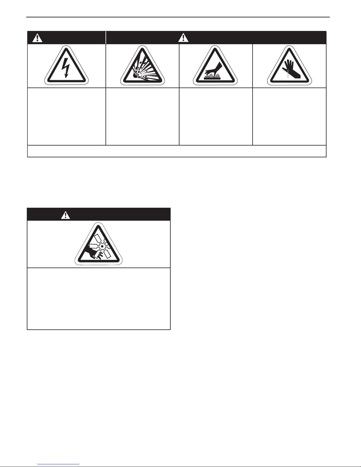
UHA LOW PROFILE UNIT HEATER INSTALLATION OPERATION AND SERVICE MANUAL
SECTION 13: SERVICING
DANGER
Electrical Shock Hazard
Disconnect electric
before service.
Heater must be
connected to a properly
grounded electrical
source.
Failure to follow these instructions can result in death, electric shock, injury or property damage.
13.1 Servicing Instructions
After start-up, the heater will require maintenance to
be carried out, at a minimum, annually. If the heater
is used in a dirty or dusty area, more frequent
maintenance may be required.
Explosion Hazard
Turn off gas supply to
heater before service.
WARNING
Burn Hazard
Allow heater to cool
before service.
Tubing may still be hot
after operation.
IMPORTANT: Check all gas pipes and pipe joints to
ensure there are no cracks or gas leaks. Any cracks
in the pipes or pipe joints must be repaired.
IMPORTANT: Inspect all suspended components
and hardware. Ensure that they are in good
condition, properly tightened, and corrosion free.
Cut/Pinch Hazard
Wear protective gear
during installation,
operation and service.
Edges are sharp.
WARNING
Severe Injury Hazard
Turn off gas and electrical supply before
service.
Fan can start automatically at any time.
Failure to follow these instructions can
result in severe injury or product damage.
IMPORTANT: Prior to any maintenance or service of
the heater, shut off, lockout and tagout the electrical
disconnect and gas valve that supplies the unit in
accordance with OSHA regulations. After any
maintenance or repair work, always test fire the
heater in accordance with the start-up instructions
on Page 28, Section 11 through Page 31, Section
11.7 to help ensure all safety systems are in working
order before leaving the heater to operate. Minor
faults may be traced by using the troubleshooting
charts on Page 37, Section 14 through Page 41,
Section 14.5.
13.2 Burner Maintenance
1. Open the hinged door and remove from the
hinges. Set door aside. See Page 43, Section
15.2.
2. Remove burner side panel. Electrode and
flame probe should remain attached. See Page
44, Section 15.3.
3. Remove burner assembly from cabinet via four
screws, two on top and two on bottom. Clean
any deposits from the main burner which may
have formed in the injectors or venturi of the
burner.
4. Check condition of ignition electrode and flame
probe. Clean off any deposits which may have
formed, check condition of ceramic insulators.
Replace as required. See Page 44, Section
15.3.
13.3 Fan/Motor Assembly Maintenance
The main fan bearings are permanently sealed and
do not need lubrication. Before cleaning, turn off gas
and electrical supply. Remove the fan and use a
small brush or duster to clean the fan blades from
each side. Replace fan when done. See Page 47,
Section 15.9.
34 of 51
Page 43
SECTION 13: SERVICING
13.4 Heat Exchanger Maintenance
The heat exchanger will remain clean unless a
problem has developed with combustion. Inspect the
heat exchanger. Look for signs of overheating at the
front tubes which may indicate burner over firing or
persistently low air flows.
13.5 Gas Valve Maintenance
No regular maintenance is required on this device.
To change gas control valves, See Page 42, Section
15.1.
Do not repair or disassemble gas valve.
Replace faulty gas valves with replacement parts
sold and supplied by Weather-Rite LLC.
13.6 Flue Blower
The flue blower should not require maintenance.
However, if the air pressure switch is causing burner
lockout, then remove the flue blower from the vent
box by unscrewing the screws at the mounting plate.
Screw quantity will vary by model size. Remove the
screws attaching the mounting plate to the fan inlet.
See Page 46, Section 15.6. Ensure that the fan is
free to run and that the fan wheel is clean.
13.7 Venting and Air Intake Pipe
Inspect all venting and air intake pipe. Ensure that
all seams are sealed and suspension points secure.
Repair suspension points if any part of the venting
or combustion air pipe is sagging. Check to make
sure any insulation is not missing or in poor
condition. Replace as necessary. Check all venting
and air intake components to ensure they are in
good condition, gas tight and corrosion-free.
13.8 Maintenance Checklist
Installation Code and Annual Inspections: All
installations and service of WEATHER-RITE
™
equipment must be performed by a contractor
qualified in the installation and service equipment
sold and supplied by Weather-Rite LLC and conform
to all requirements set forth in the WEATHER-RITE
™
manuals and all applicable governmental authorities
pertaining to the installation, service, operation and
labeling of the equipment.
To help facilitate optimum performance and safety,
Weather-Rite LLC recommends that a qualified
contractor conduct, at a minimum, annual
inspections of your WEATHER-RITE
™
equipment
and perform service where necessary, using only
replacement parts sold and supplied by WeatherRite LLC.
Annual Fall Start Up Follow entire start-up procedure at this time and check control settings and
operation.
The Vicinity of the Heater Do not store or use flammable objects, liquids or vapors near the heater.
Immediately remove these items if they are present.
See Page 6, Section 3.
Vehicles and Other
Objects
Maintain the clearances to combustibles.
Do not hang anything from, or place anything on, the heater.
Make sure nothing is lodged in between the heat exchanger or in the louvers.
Immediately remove objects in violation of the clearances to combustibles.
See Page 7, Section 4.
Vent Pipe/Terminals Venting must be intact. Using a flashlight, look for obstructions, cracks on the
pipe, gaps in the sealed areas or corrosion.
The area must be free of dirt and dust.
Remove any carbon deposits or scale using a wire brush.
If the vent terminal has a screen built in, remove any dirt, dust or deposits
from the screen.
See Page 14, Section 7 through Page 21, Section 8.
Cabinet Exterior After installation, touch up scratches. Periodic painting should be done there-
after as required. Warning labels and logo labels should be legible and accu-
™
rate. Please contact Weather-Rite LLC or WEATHER-RITE
independent
distributor if you need replacement warning labels or logo labels.
See Page 2, Figure 1 through Page 4, Figure 3.
35 of 51
Page 44
UHA LOW PROFILE UNIT HEATER INSTALLATION OPERATION AND SERVICE MANUAL
Combustion Air Intake
Pipe
Intake pipe and inlet must be intact. Look for obstructions, cracks on the pipe,
gaps in the sealed areas or corrosion.
The area must be free of dirt and dust.
Clean and reinstall as required.
See Page 21, Section 8.
Heat Exchanger Make sure there are no cracks.
Make sure there is no sagging, bending or distortion.
Clean or replace as required..
Gas Line and Shut-off
Valves
Burner Observation
Window
Flue Blower Scroll, Wheel
and Motor
Inshot Burners and
Orifices
Check for gas leaks.
See Page 22, Section 9.
Make sure it is clean and free of cracks or holes.
Clean and replace as required.
Compressed air or a vacuum cleaner may be used to clean dust and dirt.
Clear obstructions (even spider webs will cause problems).
Carefully remove any dust and debris from the burner.
Direct-Spark Igniter Replace if there are cracked ceramics, excessive carbon residue, or erosion
of the electrode.
The electrode gap should be 1/8" (3.2 mm).
Thermostat There should be no exposed wire or damage to the device or wiring.
See Page 24, Section 10.
Suspension Points Make sure the heater is hanging securely.
Look for signs of wear on the suspension materials or ceiling.
See Page 11, Figure 5.
Silicone Tubing Ensure tight, secure fit on all pressure fittings at pressure switch and vent box.
Gas Valve Verify that cap covering pressure regulator adjustment screw is secure and
has not been tampered with.
Verify all wiring connections.
Condensate Drain
(when installed)
Flush drain and clear any obstructions.
Wall Tag If wall tag is present, make sure it is legible and accurate. Please contact
Weather-Rite LLC or WEATHER-RITE
™
independent distributor if you need a
wall tag. See Page 5, Section 2.1.
36 of 51
Page 45
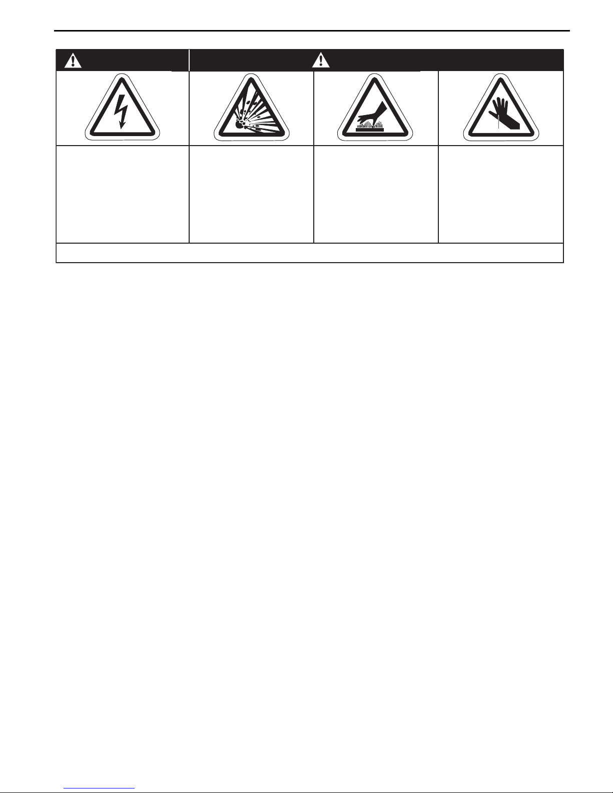
SECTION 14: TROUBLESHOOTING
SECTION 14: TROUBLESHOOTING
DANGER
Electrical Shock Hazard
Disconnect electric
before service.
Heater must be
connected to a properly
grounded electrical
source.
Failure to follow these instructions can result in death, electric shock, injury or property damage.
Explosion Hazard
Turn off gas supply to
heater before service.
WARNING
Burn Hazard
Allow heater to cool
before service.
Tubing may still be hot
after operation.
Cut/Pinch Hazard
Wear protective gear
during installation,
operation and service.
Edges are sharp.
37 of 51
Page 46
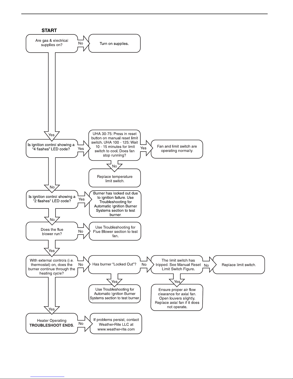
UHA LOW PROFILE UNIT HEATER INSTALLATION OPERATION AND SERVICE MANUAL
14.1 General
38 of 51
Page 47
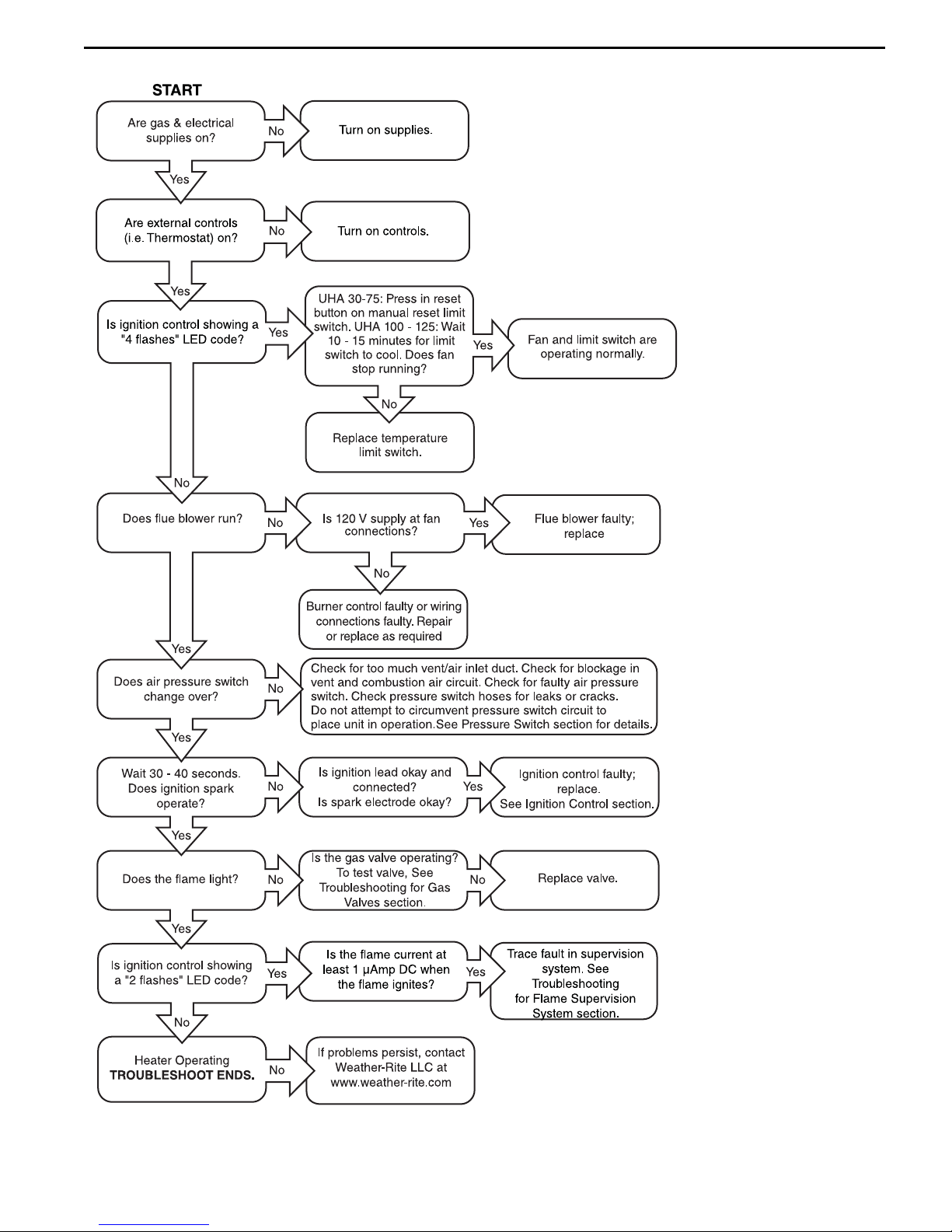
14.2 Troubleshooting For Automatic Ignition Burner Systems
SECTION 14: TROUBLESHOOTING
For optimum heater performance, use only replacement parts sold and supplied by Weather-Rite LLC.
Conduct start-up procedure as shown on Page 28, Section 11.
39 of 51
Page 48
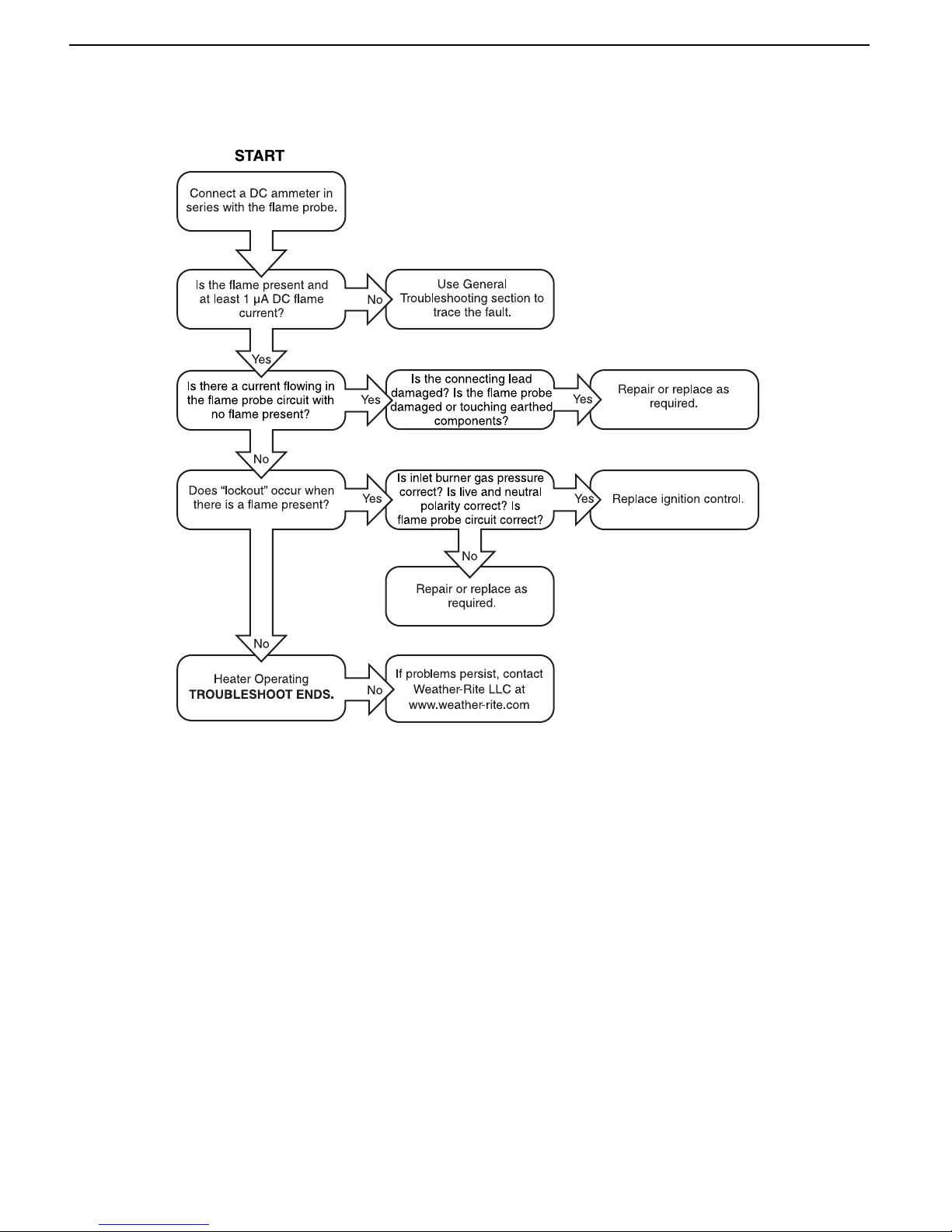
UHA LOW PROFILE UNIT HEATER INSTALLATION OPERATION AND SERVICE MANUAL
14.3 Troubleshooting for Flame Supervision System
To measure flame current, connect a 0 - 50 µA DC meter in series with the flame probe. If the meter
reads negative values, then reverse the test leads.
NOTE: Minimum flame probe current 1 µA DC. Typical flame probe current 3-5 µA DC.
40 of 51
Page 49
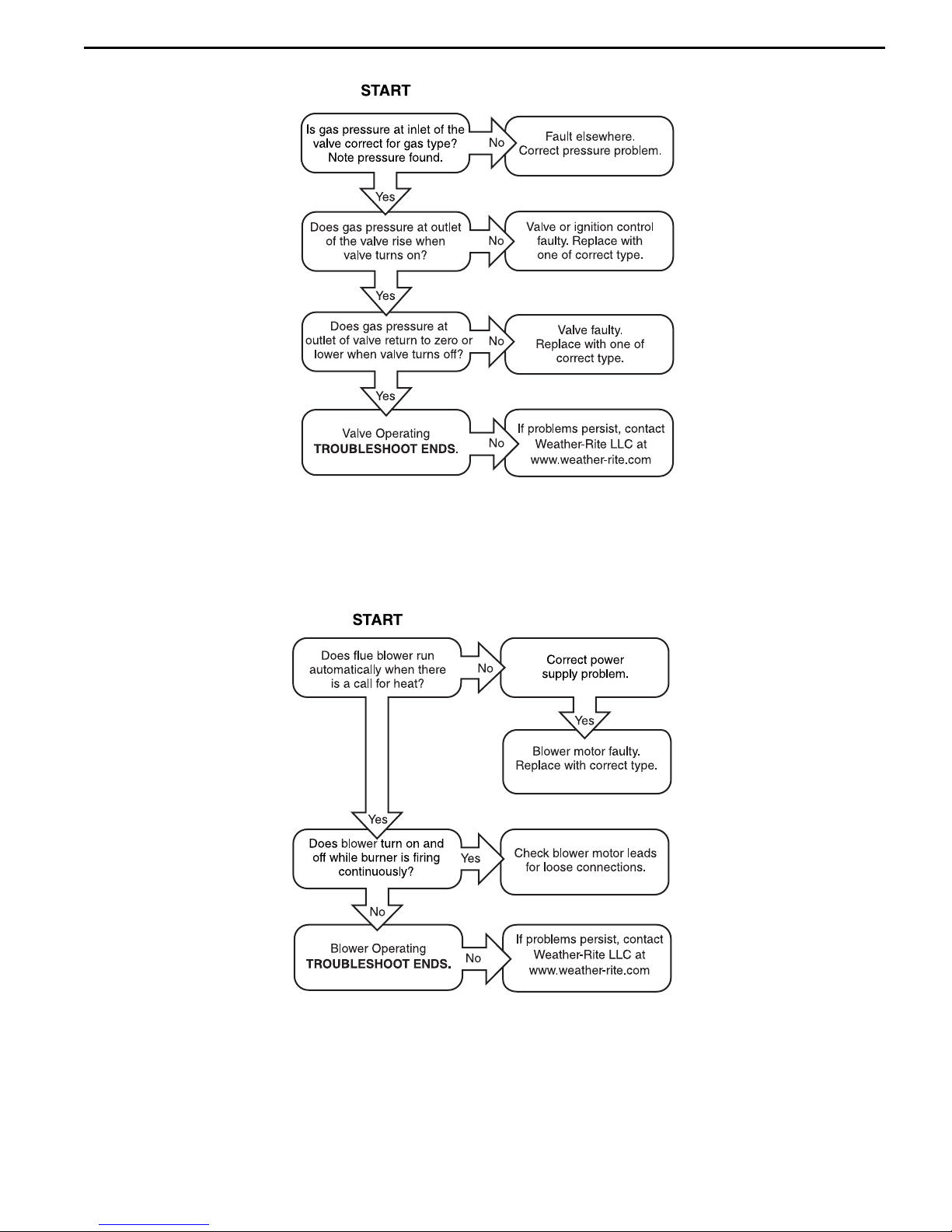
14.4 Troubleshooting for Gas Valves
SECTION 14: TROUBLESHOOTING
14.5 Troubleshooting for Flue Blower
For optimum heater performance, use only replacement parts sold and supplied by Weather-Rite LLC.
Conduct start-up procedure as shown on Page 28, Section 11.
41 of 51
Page 50
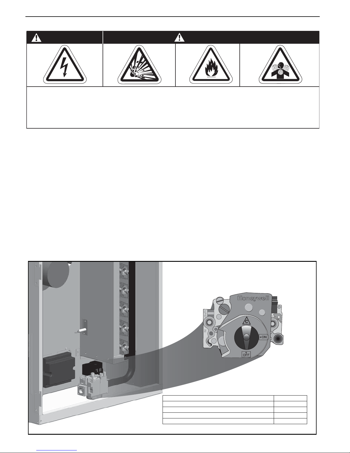
UHA LOW PROFILE UNIT HEATER INSTALLATION OPERATION AND SERVICE MANUAL
SECTION 15: REPLACEMENT PARTS
DANGER
Electrical Shock Hazard
Use only genuine WEATHER-RITE™ replacement parts per this installation, operation and service
manual.
Failure to follow these instructions can result in death, electric shock, injury or property damage.
See warnings and important information on Page
34, Section 13 before removing or replacing parts.
Burner Components
All serviceable burner parts are accessed by the
hinged door on the side of the heater.
Explosion Hazard
WARNING
Fire Hazard
15.1 Gas Valve
Remove the gas supply pipe at the heater inlet.
Follow instructions on Page 43, Section 15.2 to
remove gas valve/manifold.
Replace in reverse order. Verify that the gas flow
direction of the valve is correct. Use a minimum
amount of gas seal on the thread joint. Check that
all the joints are leak free. Reset gas valve. See
Page 30, Section 11.2.2.
IT IS IMPORTANT THAT ONLY THE CORRECT
GAS VALVE IS USED WHEN REPLACING THESE
CONTROLS.
Carbon Monoxide Hazard
42 of 51
Description Part Number
Gas Valve, NG (Models UHA[X][S] 30 - 45) 90034500
Gas Valve, LP (Models UHA[X][S] 30 - 45) 90034600
Gas Valve, NG (Models UHA[X][S] 60 - 125) 90032505
Gas Valve, LP (Models UHA[X][S] 60 - 125) 90032506
Page 51
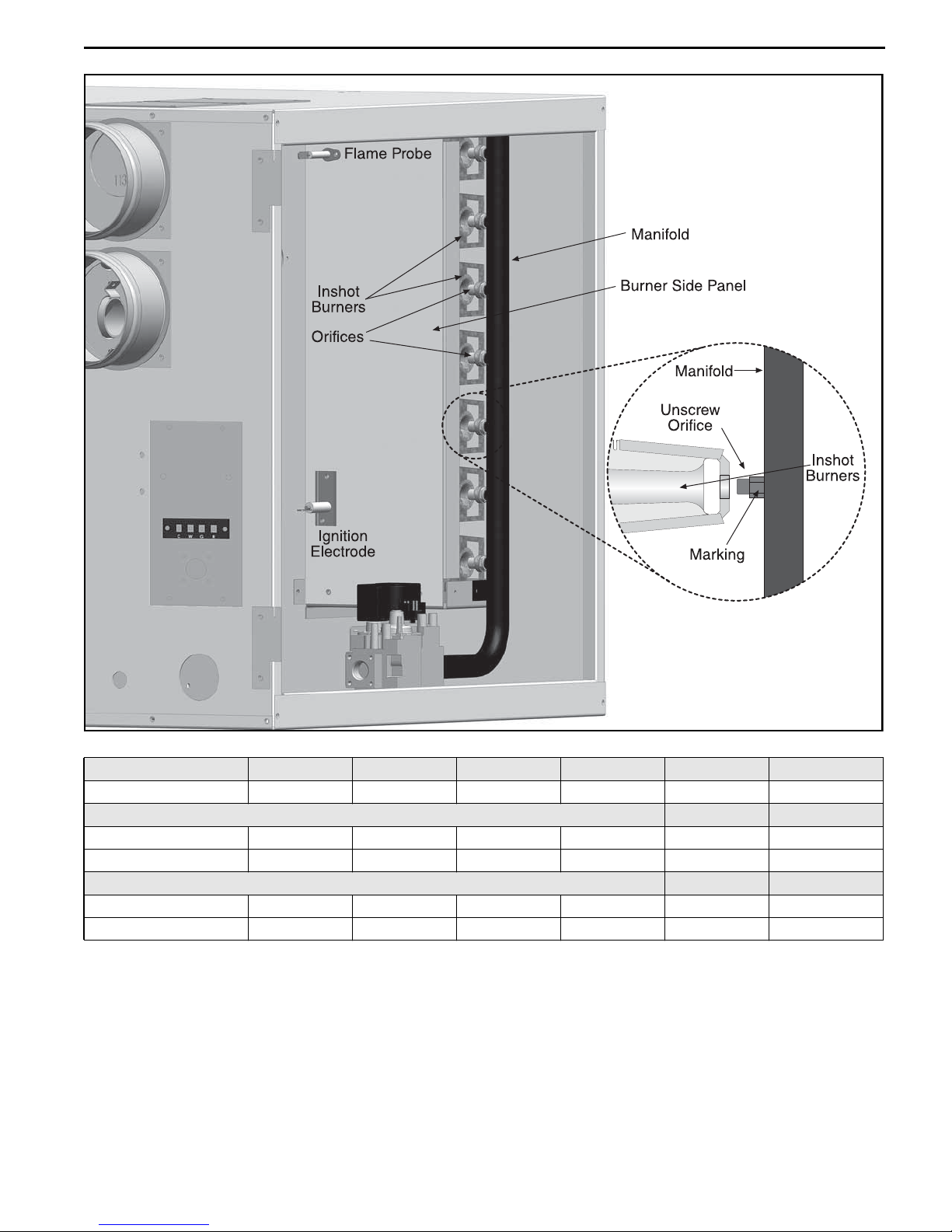
15.2 Burner Injectors
SECTION 15: REPLACEMENT PARTS
Remove four screws to remove
manifold.
Ensure gas tight fitting of injectors.
Ensure correct
alignment with
burners.
Ensure all pipe joints are gas tight.
MODEL UHA[X][S] 30 UHA[X][S] 45 UHA[X][S] 60 UHA[X][S] 75 UHA[X][S] 100 UHA[X][S] 125
Orifice Quantity 2 3 4 5 6 7
Natural Gas
Orifice Marking 49 49 49 49 46 46
P/N 91930049 91930049 91930049 91930049 91930046 91930046
Propane
Orifice Marking 56 56 56 1.15 mm 1.25 mm 1.25 mm
P/N 91930056 91930056 91930056 91930115 91930125 91930125
43 of 51
Page 52
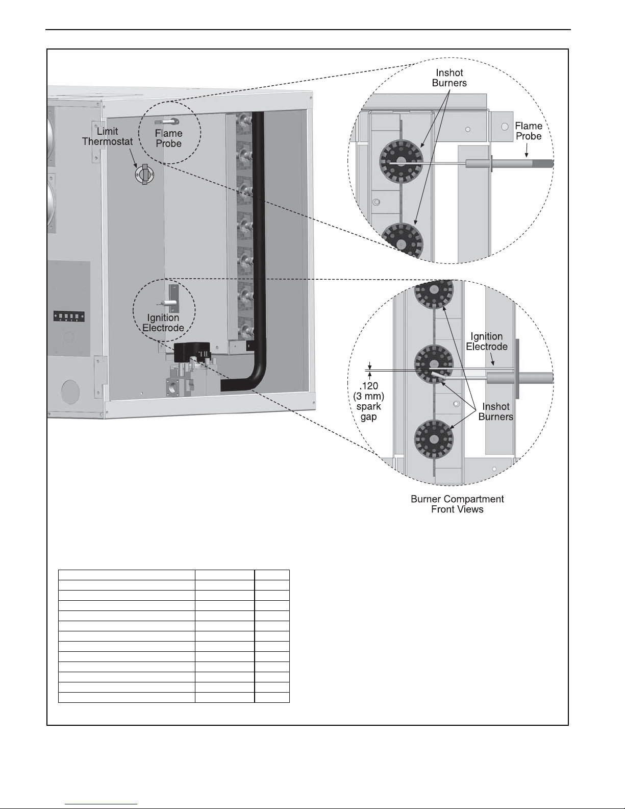
UHA LOW PROFILE UNIT HEATER INSTALLATION OPERATION AND SERVICE MANUAL
15.3 Ignition Electrode and Flame Probe
To replace the electrode or flame probe, remove the electrical lead and screw.
Pull out from mounting. Refit in reverse ensuring that the gap to burner is as shown in the front view of
the burner compartment.
Description Part Number Qty
Spark Electrode 90427411 1
Automatic Ignition Flame Probe 90439300 1
Transformer 90436900K 1
Ignition Module 90434008 1
Inshot Burners UHA[X][S] 30 92000002 2
Inshot Burners UHA[X][S] 45 92000002 3
Inshot Burners UHA[X][S] 60 92000002 4
Inshot Burners UHA[X][S] 75 92000002 5
Inshot Burners UHA[X][S] 100 92000002 6
Inshot Burners UHA[X][S] 125 92000002 7
Limit Switch 90412104 1
Manual Reset Limit Switch* 90412106 1
*UHA 30-75 only.
44 of 51
Page 53
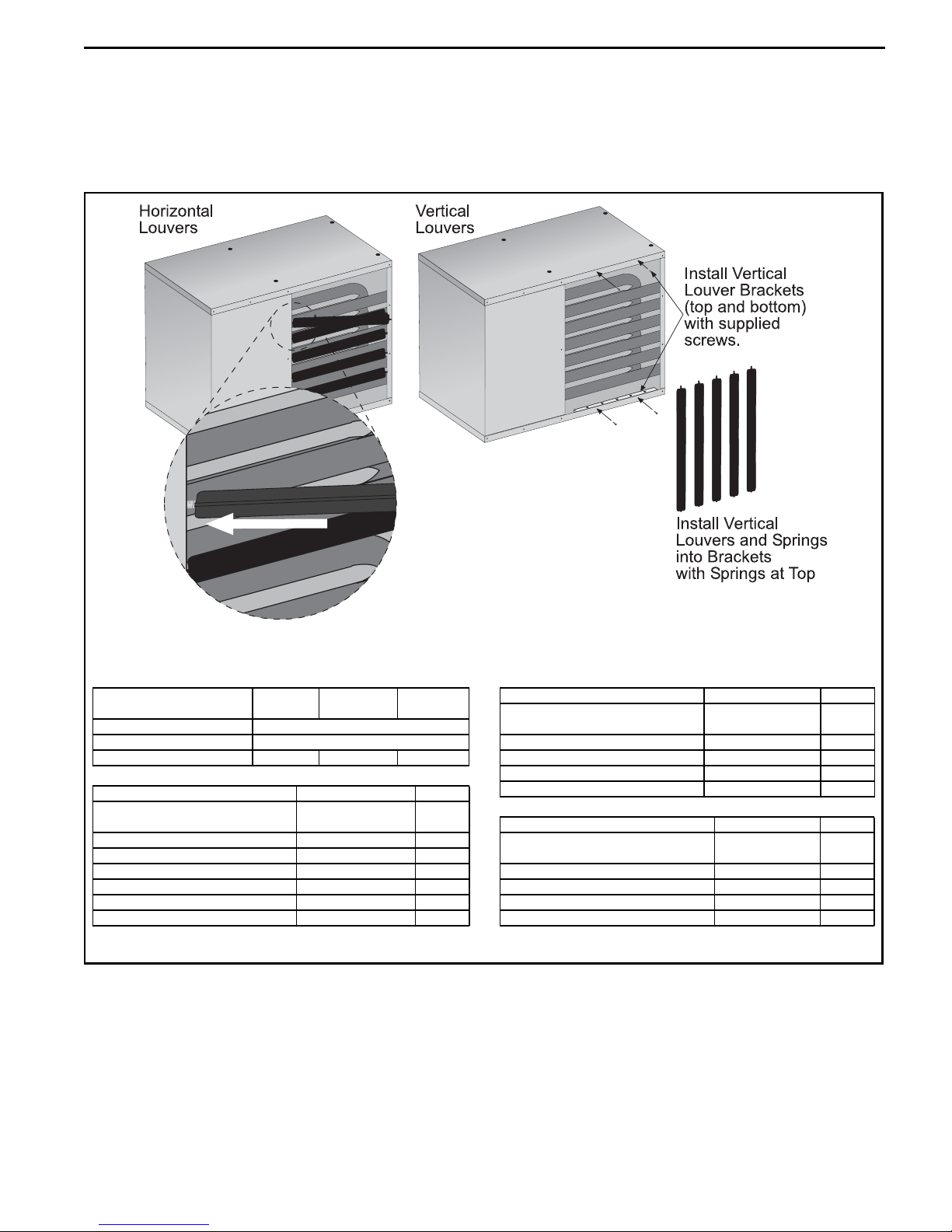
SECTION 15: REPLACEMENT PARTS
15.4 Heat Exchanger
The heat exchanger consists of a six-pass design with 1.5" outer diameter [aluminized steel][409 stainless
steel] tube. The tube plates are made of [aluminized steel][409 stainless steel]. The tube supports are
made of [aluminized steel] [409 stainless steel].
15.5 Louver and Louver Springs
For models UHA[X][S] 60 and UHA[X][S] 75, horizontal louvers are re-used.
Description
Horizontal Louvers P/N 11111900
Spring P/N 91901200
Quantity 3 5 7
Description Part Number Qty.
Vertical Louver Kit UHA[X][S] 30
& UHA[X][S] 45
Vertical Louver Bracket - 2
UHA[X][S] 30 - 45 Vertical Louvers - 4
Louver Spring - 5
Instruction Sheet - 2
#10 Screw - 1
#10 Screw - 4
UHA[X][S]
30 - 45
UHA[X][S]
60 - 75
12011003K
UHA[X][S]
100 - 125
Description Part Number Qty.
Vertical Louver Kit UHA[X][S] 60
& UHA[X][S] 75
Vertical Louver Bracket - 2
UHA[X][S] 60 - 75 Vertical Louvers - 5
Instruction Sheet - 1
#10 Screw - 4
Description Part Number Qty.
Vertical Louver Kit UHA[X][S] 100 &
UHA[X][S] 125
Vertical Louver Bracket - 2
UHA[X][S] 100 - 125 Vertical Louvers - 5
Instruction Sheet - 1
#10 Screw - 4
12011005K
12011004K
45 of 51
Page 54
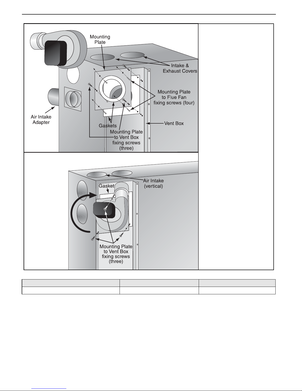
UHA LOW PROFILE UNIT HEATER INSTALLATION OPERATION AND SERVICE MANUAL
15.6 Flue Blower Vertical Installation for UHA[X][S] 30 - 75 Only
To remove the blower,
remove screws securing the
fan and mounting plate to
the vent box.
To remove the blower from
the mounting plate, remove
screws.
Refit in reverse order.
To change the vent and air
intake orientation from back
to top, remove the blower
and mounting plate as
above.
Remove intake and exhaust
covers from top of the
heater.
Rotate the blower, mounting
plate and gasket clockwise
until the flue adapter lines
up with the top hole. Secure
screws.
If applicable, remove the air
intake adapter from the back
of the heater and install in
the appropriate hole on top.
Install intake and exhaust
covers over the back holes.
Ensure sealed joints.
Ensure mounting plate
orifice is clear and not
obstructed.
MODEL UHA[X][S] 30 -75 UHA[X][S] 100 - 125
Flue Blower P/N 90710404 90710403
IT IS IMPORTANT THAT ONLY THE CORRECT FLUE BLOWER SPECIFIED FOR EACH MODEL TYPE
IS USED WHEN REPLACING THESE ITEMS.
Carry out a start-up after working on or changing an flue blower. See Page 28, Section 11.
46 of 51
Page 55
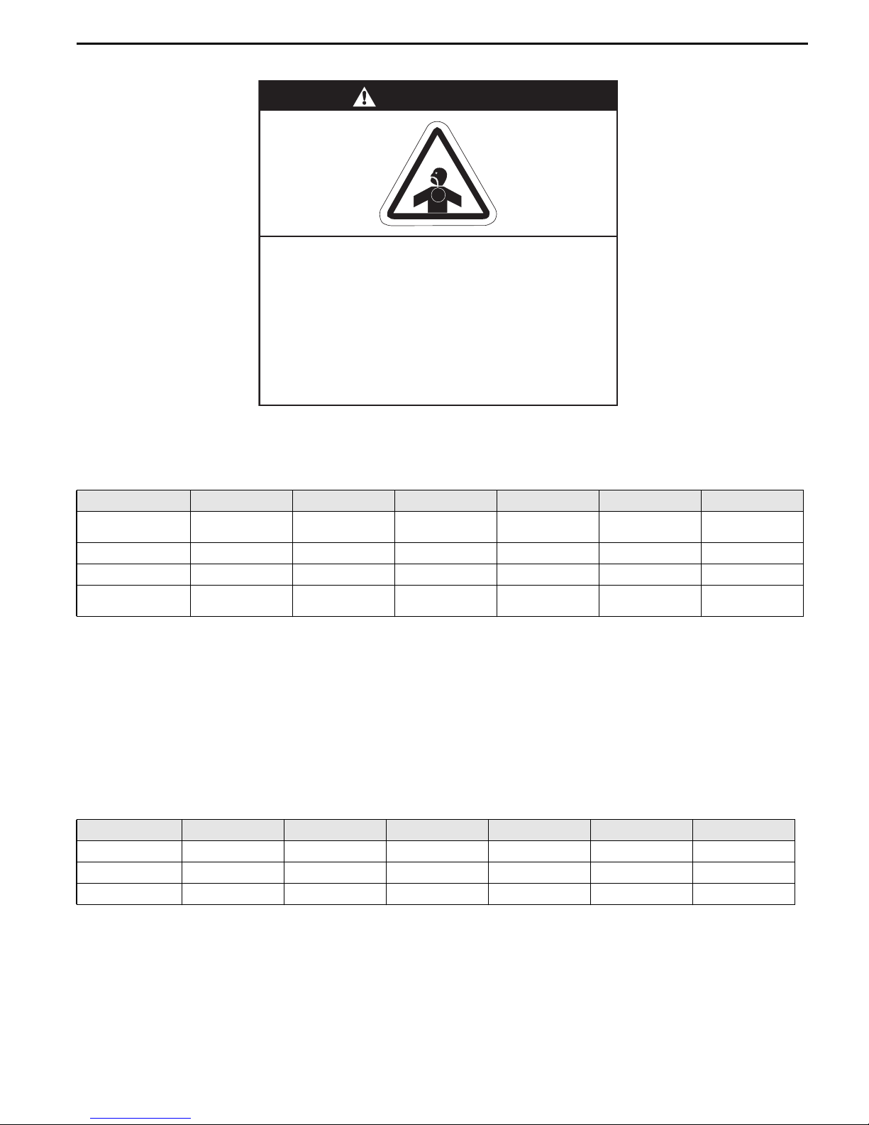
SECTION 15: REPLACEMENT PARTS
15.7 Pressure Switch
WARNING
Carbon Monoxide Hazard
Use correct pressure switch specified for each
model.
Use of incorrect pressure switch or disabling
pressure switch circuit could cause unsafe
condition.
Failure to follow these instructions can result in
death or serious injury.
Pull off 3 way connector. Spring open plastic clips of mounting cradle. Replace with correct type of pressure
switch for model. The pressure switches are color coded for each pressure setting. Carry out a start-up
after working on or changing a pressure switch. See Page 28, Section 11.
MODEL UHA[X][S] 30 UHA[X][S] 45 UHA[X][S] 60 UHA[X][S] 75 UHA[X][S] 100 UHA[X][S] 125
Pressure Switch
Kit P/N
Color Code
Set Point in. wc
Pressure Switch
Snap Ring P/N
90439804 90439804 90439804 90439804 90439805 90439803
white white white white blue grey
0.47 0.47 0.47 0.47 0.55 0.41
90439850 90439850 90439850 90439850 90439850 90439850
15.8 Ignition Control
The control mounts to the heat exchanger plate. Pull out ignition cable and wiring from board, noting their
positions. Release the four mounting standoffs. Refit in reverse. Ensure correct location of ignition cable
and all other wiring.
15.9 Axial Fan/Guard/Motor Assembly
The axial fan unit for the heater is supplied completely assembled and balanced.
MODEL UHA[X][S] 30 UHA[X][S] 45 UHA[X][S] 60 UHA[X][S] 75 UHA[X][S] 100 UHA[X][S] 125
Axial Fan Guard 91901103 91901103 91901102 91901102 91901102 91901102
Axial Fan Motor 90600104 90600104 90600105 90600105 90600106 90600106
Axial Fan Blade 90709004 90709003 90709002 90709001 90709001 90709001
47 of 51
Page 56
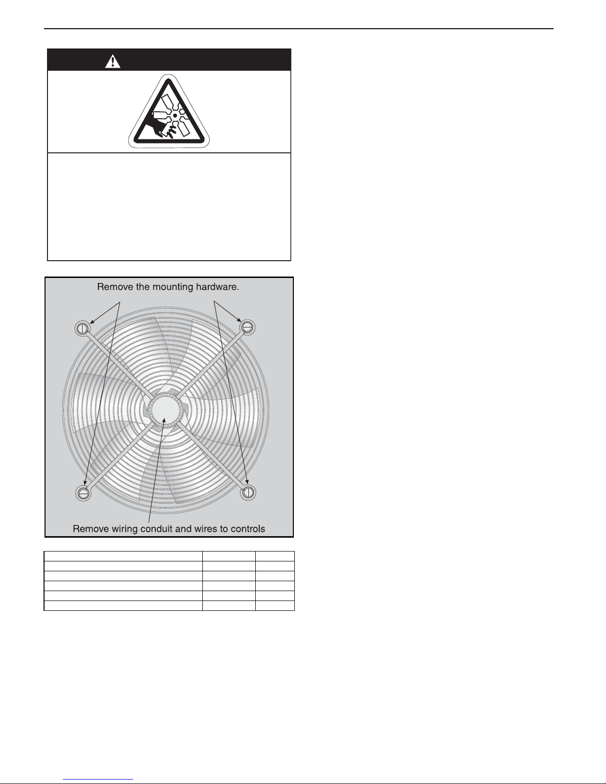
UHA LOW PROFILE UNIT HEATER INSTALLATION OPERATION AND SERVICE MANUAL
15.9.1 Fan Removal and Replacement
WARNING
Severe Injury Hazard
Turn off gas and electrical supply before
service.
Fan can start automatically at any time.
Failure to follow these instructions can
result in severe injury or product damage.
• Use only genuine replacement parts sold and
supplied by Weather-Rite LLC.
15.10 Limit Switches
15.10.1 Removal and Replacement
1. Remove the electrical connections to the
switch.
2. Unscrew the two screws securing the
switch.
3. Fit a new switch with two screws.
4. Reconnect the electrical connections and test
operation.
Description Part Number Quantity
Axial Fan UHA[X][S] 30 12011910 1
Axial Fan UHA[X][S] 45 12011911 1
Axial Fan UHA[X][S] 60 12011920 1
Axial Fan UHA[X][S] 75 12011921 1
Axial Fan UHA[X][S] 100 and UHA[X][S] 125 12011922 1
15.9.2 To Replace the Fan Assembly
To replace the fan assembly, reverse the procedure
shown above.
• Check that the fan blades are free to rotate
before turning on the power to the fan.
• Strictly comply with the color code of the fan
wires to ensure correct operation. See Page 25,
Section 10.3 wiring diagram.
48 of 51
Page 57
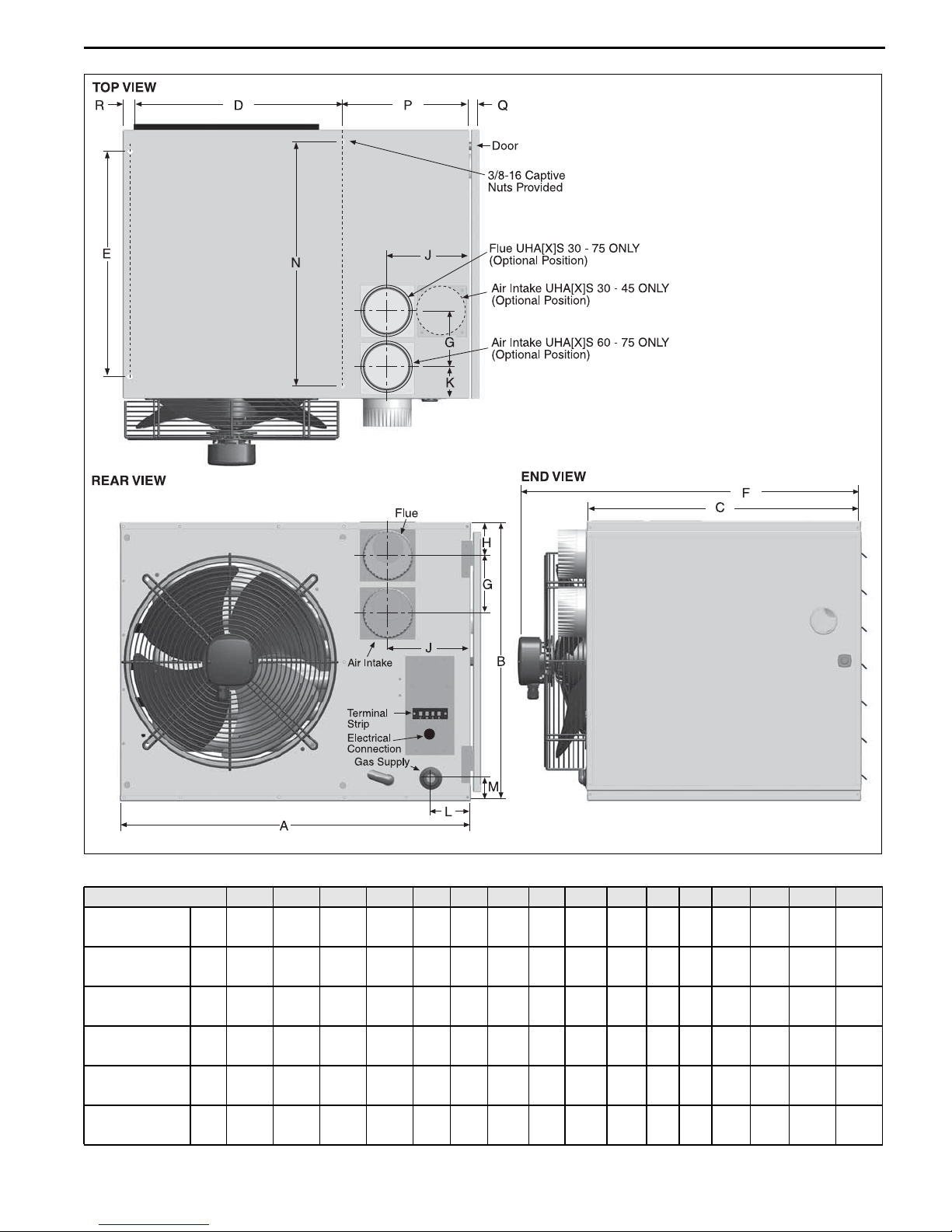
SECTION 16: SPECIFICATIONS
SECTION 16: SPECIFICATIONS
16.1 Dimension Data
Models A B C D E F G H J K L M N P Q R
UHA[X][S]30
in cm28.7
73.0
UHA[X][S]45
in cm28.7
73.0
UHA[X][S]60
in cm28.7
73.0
UHA[X][S]75
in cm28.7
73.0
UHA[X][S]100
in cm28.7
73.0
UHA[X][S]125
in cm28.7
73.0
11.9
30.2
11.9
30.2
17.7
45.0
17.7
45.0
22.7
57.6
22.7
57.6
22.3
56.6
22.3
56.6
22.3
56.6
22.3
56.6
22.3
56.6
22.3
56.6
17.6
44.7
17.6
44.7
17.6
44.7
17.6
44.7
17.6
44.7
17.6
44.7
18.6
28.0
47.2
71.1
18.6
28.0
47.2
71.1
18.6
28.0
47.2
71.1
18.6
28.0
47.2
71.1
18.6
28.0
47.2
71.1
18.6
28.0
47.2
71.1
4.8
2.6
12.1
6.6
4.8
2.6
12.1
6.6
5.0
2.8
12.7
7.1
5.0
2.8
12.7
7.1
4.7
8.6
11.9
21.8
4.7
8.6
11.9
21.8
7.2
5.8
18.3
14.7
7.2
5.8
18.3
14.7
6.8
7.5
17.3
19.1
6.8
7.5
17.3
19.1
6.8
17.3--
6.8
17.3--
3.3
8.4
3.3
8.4
3.3
8.4
3.3
8.4
3.3
8.4
3.3
8.4
1.6
4.1
1.6
4.1
1.9
4.8
1.9
4.8
1.9
4.8
1.9
4.8
20.3
10.4
51.6
26.4
20.3
10.4
51.6
26.4
20.3
10.4
51.6
26.4
20.3
10.4
51.6
26.4
20.3
10.4
51.6
26.4
20.3
10.4
51.6
26.4
0.6
1.5
0.6
1.5
0.6
1.5
0.6
1.5
0.6
1.5
0.6
1.5
49 of 51
0.5
1.4
0.5
1.4
0.5
1.4
0.5
1.4
0.5
1.4
0.5
1.4
Page 58
UHA LOW PROFILE UNIT HEATER INSTALLATION OPERATION AND SERVICE MANUAL
16.2 General Technical Data Table
Model
Full Load Amps @ 120 V A 3.0 3.0 4.1 4.1 5.8 5.8
Air Volume CFM 691 691 1376 1376 1902 1902
Flue and Air Intake
Flue and Air Intake Size in (cm) 4 (10) - All Models
*Maximum Straight Flue/Air Intake ft (m) 25 (7.6) 25 (7.6) 25 (7.6) 25 (12.2) 40 (12.2) 40 (12.2)
Weight (Net) lbs (kg) 65 (29.5) 70 (31.8) 85 (38.6) 90 (40.8) 105 (47.6) 110 (49.9)
UHA[X][S] 30UHA[X][S]45UHA[X][S] 60UHA[X][S] 75UHA[X][S]
100
UHA[X][S]
125
*Do not exceed the maximum length of flue stated or heater may not operate properly.
16.3 Technical Data Table
Model
Total Input (Btu/h) x (1000) 30 45 60 75 100 125
Total Output (Btu/h) x (1000) 24.6 36.9 49.2 61.5 82 102.5
UHA[X][S] 30UHA[X][S] 45UHA[X][S] 60UHA[X][S] 75UHA[X][S]
100
UHA[X][S]
125
Efficiency % 82 - All Models
Natural Gas Data - Inlet Pressure 5.0 in wc Min., 14 in wc Max.
Burner Pressure in wc 3.7 3.6 3.7 3.5 2.8 3.1
LPG / Propane Data - Inlet Pressure 12.0 in wc Min., 14 in wc Max.
Burner Pressure in wc 9.4 9.6 9.6 10.0 8.8 9.3
50 of 51
Page 59

™
SECTION 17: WEATHER-RITE
UHA-SERIES WARRANTY
WEATHER-RITE LLC WILL PAY FOR:
Within 24 months from date of purchase by buyer or 27
months from the date of shipment by Weather-Rite LLC
(whichever comes first), replacement parts will be
provided free of charge for any part of the product which
fails due to a manufacturing or material defect.
Weather-Rite LLC will require the part in question to be
returned to the factory. Weather-Rite LLC will, at its sole
discretion, repair or replace after determining the nature
of the defect and disposition of part in question.
WEATHER-RITE™ Replacement Parts are warranted for a
period of 18 months from date of shipment from WeatherRite LLC or the remaining WEATHER-RITE™ UHA-Series
warranty.
WEATHER-RITE LLC WILL NOT PAY FOR:
Service trips, service calls and labor charges.
Shipment of replacement parts.
Claims where the total price of the goods have not
been paid.
Damage due to:
• Improper installation, operation or maintenance.
• Misuse, abuse, neglect, or modification of the
WEATHER-RITE™ UHA-Series in any way.
• Use of the WEATHER-RITE™ UHA-Series for other
than its intended purpose.
• Incorrect gas or electrical supply, accident, fire, floods,
acts of God, war, terrorism, or other casualty.
• Improper service, use of replacement parts or
accessories not specified by Weather-Rite LLC.
• Failure to install or maintain the WEATHER-RITE™
UHA-Series as directed in the Installation, Operation
and Service manual.
• Relocation of the WEATHER-RITE™ UHA-Series after
initial installation
• The use of the WEATHER-RITE™ UHA-Series in a
corrosive atmosphere containing contaminants.
• The use of the WEATHER-RITE™ UHA-Series in the
vicinity of a combustible or explosive material.
• Any defect in the WEATHER-RITE™ UHA-Series
arising from a drawing, design, or specification
supplied by or on behalf of the consumer.
• Damage incurred during shipment. Claim must be
filed with carrier.
WARRANTY IS VOID IF:
The WEATHER-RITE™ UHA-Series is not installed by a
contractor qualified in the installation and service of gasfired heating equipment.
You cannot prove original purchase date and required
annual maintenance history.
The data plate and/or serial number are removed,
defaced, modified or altered in any way.
The ownership of the WEATHER-RITE™ UHA-Series is
moved or transferred. This warranty is nontransferable.
SECTION 17: WEATHER-RITE™ UHA-SERIES WARRANTY
Weather-Rite LLC is not permitted to inspect the
damaged controller and/or component parts.
READ YOUR INSTALLATION, OPERATION AND
SERVICE MANUAL
If you have questions about your controller, contact your
installing professional. Should you need Replacement
Parts or have additional questions, call or write:
Weather-Rite LLC
616 North 5th Street
Minneapolis, MN 55401
Telephone: +1.612.338.1401
Fax: +1.612.338.6783
Toll Free: 800.589.3691
www.weather-rite.com
Weather-Rite LLC' liability, and your exclusive
remedy, under this warranty or any implied warranty
(including the implied warranties of merchantability
and fitness for a particular purpose) is limited to
providing replacement parts during the term of this
warranty. Some jurisdictions do not allow limitations on
how long an implied warranty lasts, so this limitation may
not apply to you. There are no rights, warranties or
conditions, expressed or implied, statutory or otherwise,
other than those contained in this warranty.
Weather-Rite LLC shall in no event be responsible for
incidental or consequential damages or incur liability
for damages in excess of the amount paid by you for
the WEATHER-RITE™ UHA-Series. Some jurisdictions
do not allow the exclusion or limitation of incidental or
consequential damages, so this limitation or exclusion
may not apply to you. This warranty gives you specific
legal rights, and you may also have other rights which
vary from jurisdiction to jurisdiction.
Weather-Rite LLC shall not be responsible for failure to
perform under the terms of this warranty if caused by
circumstances out of its control, including but not limited
to war, fire, flood, strike, government or court orders, acts
of God, terrorism, unavailability of supplies, parts or
power. No person is authorized to assume for WeatherRite LLC any other warranty, obligation or liability.
LIMITATIONS ON AUTHORITY OF
REPRESENTATIVES:
No representative of Weather-Rite LLC, other than an
Executive Officer, has authority to change or extend these
provisions. Changes or extensions shall be binding only if
confirmed in writing by Weather-Rite LLC's duly
authorized Executive Officer.
51 of 51
Page 60

Page 61
Page 62

Page 63

Page 64
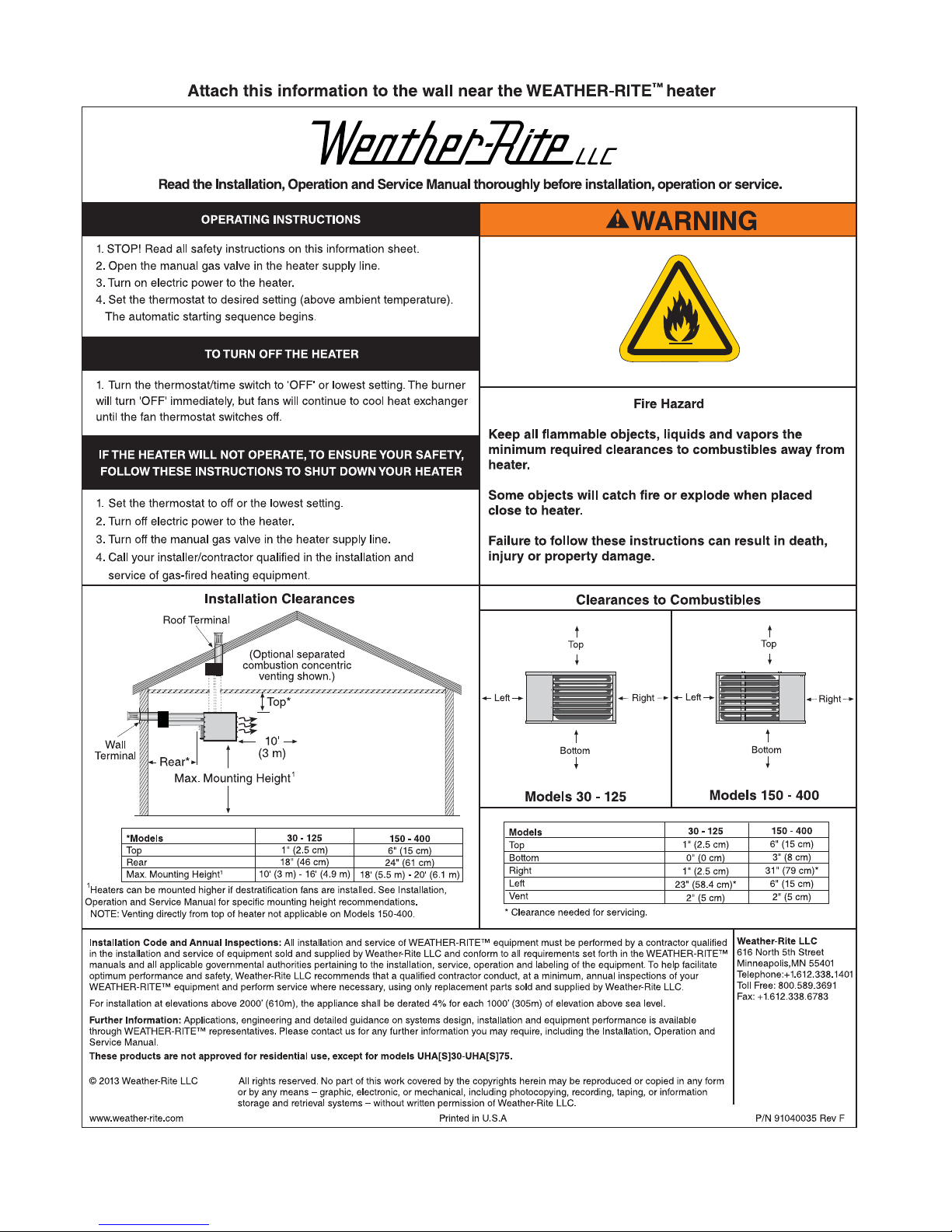
 Loading...