

Page 1
TRUCK STORAGE SOLUTIONS
FOR THE WAY YOU WORK™
INSTALLATION MANUAL
LO SIDE BOX ADD-ON KIT
For driver or passenger side congurations
Model: QDKSBDO1 -or- QDKSBP01
(passenger side)(driver side)
Weather Guard / Knaack 800-456-7865 Toll Free
420 E. Terra Cotta Ave 800-334-2981 Fax
Crystal Lake, IL 60014 USA Knaack.OrderEntry@wernerco.com
Weather Guard / Knaack 888-562-2251 Toll Free
185A Courtneypark Drive East 888-456-8460 Fax
Mississauga, ON I.5T 2T6 Knaack.OrderEntry.Canada@wernerco.com
Part No. 24-0327
Rev. A
ECN 5430
Page 2
ATTENTION: PLEASE READ AND UNDERSTAND ALL INSTRUCTIONS
AND WARNINGS BEFORE ASSEMBLING, INSTALLING OR USING THIS
PRODUCT.
CAUTION
Be safe - always wear protective eye wear to keep debris out of your eyes when
installing WEATHER GUARD® Truck Products
WARNING
Prior to drilling, check under vehicle for fuel, tanks, fuel lines, brake lines, electric wires,
etc. To avoid cutting or puncturing them. Do not use Blind Fasteners in these areas.
Tools Needed
• NEEDLE NOSE PLIERS
• PHILLIPS HEAD & STANDARD HEAD SCREWDRIVER
• WIRE STRIPPER
• 5/16” WRENCH OR SOCKET
• POWER DRILL
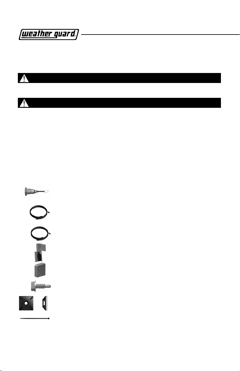
Installation Kit Includes:
WEATHER GUARD EXTREME PROTECTION® LOCK
QTY. 1 -CLIP, GASKET AND KEYS INCLUDE QTY. 1
WIRE HARNESS - 2 AVAILABLE:
DRIVER SIDE HARNESS (QDKSBD01 KIT) QTY. 1
ENGLISH
Page 2
PASSENGER SIDE HARNESS (QDKSBP01 KIT) QTY. 1
ACTUATOR, LATCH, LINK AGE & BRACKET ASSEMBLY QTY. 1
ACTUATOR ASSEMBLY COVER QTY. 1
SELF TAPPING MOUNTING SCREWS (#8-18 x 1/2”) QTY. 2
ADHESIVE SQUARES QTY. 8
WIRE TIES QTY. 8
Page 3

LO SIDE BOX
USER INSTRUCTIONS
Contents
I. SYSTEM MAINTENANCE .................................................................................4
II. MAXIMIZE THE PERFORMANCE OF YOUR SYSTEM ....................................5
III. QUICKDRAW SIDE BOX COMPATIBILITY .....................................................5
IV. MECHANICAL ASSEMBLY AND INSTALLATION .......................................... 5
V. SYSTEM CHECK ............................................................................................. 10
VI. FINAL INSTALLATION .................................................................................. 10
VII. OPERATING INSTRUCTIONS FOR REMOTE CONTROL .......................... 11
VIII. PAIRING THE FOB TO THE QUICKDRAW SYSTEM .................................. 12
Page 3
ENGLISH
Page 4

FCC:W99PI01, W99PI02 IC:8296A-PI01;8296A-PI02
This device complies with part 15 of the FCC Rules and Canada
license-exempt Rss-210 standard.
Operation is subject to the following two conditions
(1) THIS DEVICE MAY NOT CAUSE HARMFUL INTERFERENCE
(2) THIS DEVICE MUST ACCEPT ANY INTERFERENCE RECEIVED,
INCLUDING INTERFERENCE THAT MAY CAUSE UNDESIRED
OPERATION.
WARNING! SAFETY FIRST
The following safety warning must be observed at all times:
Due to the complexity of this system, installation of this product must only be performed
by an authorized Weather Guard dealer.
IMPORTANT INFORMATION
Congratulations on purchasing your QuickDraw™ Keyless Entry System. Due to the
complexity of this system, it must be installed by an authorized dealer only. Installation
of this product by anyone other than an authorized dealer voids the warranty.
By carefully reading this Owner’s Manual prior to using your system, you will maximize
the use of this system and its features. You can print additional or replacement copies of
this manual by accessing our web site at www.weatherguard.com.
I. System Maintenance
The system requires no specic maintenance. Your QuickDraw
remote is powered by a small coin cell lightweight 3-volt lithium
battery (CR2032) that lasts approximately 3 years under normal
use. When the battery begins to weaken, the operating range is
reduced.
ENGLISH
Page 4
Page 5
LO SIDE BOX
USER INSTRUCTIONS
II. Maximize the Performance of Your System
Never put the key fob together with a cellphone as this may affect
the range and its performance.
Additional antennas can be installed to extend the range of the
active zone. The installation must be done by technicians who
are trained or certied by Weather Guard dealers (optional parts
and extra labor required). Refer to your authorized dealer for more
information.
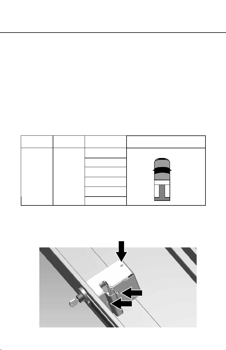
III. QuickDraw Side Box Compatibility
QuickDraw
Model
QDKSBD01 175
Driver
Weather Guard
Box Type Model
Lo Side 184
174
176
Conguration
2 side boxes with a saddle box*
Tru ck
QDKSBP01 185
Passenger
186
*Requires installation of QuickDraw saddle box
starter kit model # QDSKSA01 (sold separately)
IV. Mechanical Assembly and Installation
a. Remove the screws holding the top and side cover plates as shown
in Figures 1 & 2. Safely store cover plates and screws for use at the
end of installation.
Figure 1
ENGLISH
Page 5
Page 6

Figure 2
b. Remove the lock retaining clip holding the lock in place and pull the
lock out as shown in Figures 3 and 4. Save the retaining clip and
gasket, for use with the new lock.
Figure 3
ENGLISH
Page 6
Figure 4
Page 7

LO SIDE BOX
USER INSTRUCTIONS
c. Remove QuickDraw system module protective cover box. Save
screws for use at the end of installation.
d. Connect side box harness 4-pin connector to the corresponding
4-pin connector of the system module, see Figure 5.
Figure 5
e. Feed harness through partition wall hole at the top, and down
through gas strut protective housing. See Figure 6.
Figure 6
Page 7
ENGLISH
Page 8

f. Feed side box harness into side box through rubber grommet, see
Figure 7.
Figure 7
g. Remove the wire ties from the actuator/latch bracket assembly
provided. Connect actuator 2-pin connector with the wire harness
2-pin connector located approximately 12” from the end of the
harness, see gure 8. Pull remaining 2-pin connector plug and
harness up through the inside of the assembly (to be connected
later). Position bracket assembly into place and fasten into place
loosely using the side cover plate screws from step A as shown in
Figure 9.
Figure 8 Figure 9
ENGLISH
Page 8
Page 9

LO SIDE BOX
USER INSTRUCTIONS
h. Insert the new lock with switch and secure in place using retaining
clip and gasket as shown in Figures 10 & 11. Connect lock 2-pin
Connector with the wire harness 2-pin connector, and fully tighten
down bracket assembly.
Figure 11Figure 10
i. Secure the metal cover with the (2) screws provided and replace
the plastic top cover and secure with the screw removed in step #1.
See Figure 12.
Figure 12
Page 9
ENGLISH
Page 10

V. System Check
Testing the QuickDraw Remote (FOB)
The QuickDraw starter kit comes complete with 1 FOB, which is
pre-programmed to the System module included. If additional FOBs
are desired for the system, please see “FOB programming”.
a. Test 1: Proximity hands-free operation
1. Bring the QuickDraw remote into range (within 5ft of box).
2. Ensure truck box lid is closed and all push button locks are
in locked position.
3. Test one of the QuickDraw proximity function by depressing
and holding push button lock for approximately 2 seconds.
• If truck box opens correctly, proceed to test push the
other button lock. If both push button locks work correctly,
proceed with test 2.
• If truck box does not open correctly, double-check all
electrical connections and repeat testing.
b. Test 2: Push Button Remote Operation
1. Ensure truck box lid is closed and all push button locks are
in locked position, and QuickDraw FOB is within 100 ft of the
truck.
2. Test QuickDraw push button remote function
by depressing and holding button 1.
• If truck box opens correctly, proceed with
nal installation steps. (Buttons 2 and 3
can be programmed for optional lo-side
QuickDraw Boxes)
• If truck box does not open correctly, double-check all
electrical connections and repeat testing.
VI. Final Installation
Use velcro to attach the system module to the saddle box and use
wire ties and adhesive squares to hold the wire harness in place
where needed.
ENGLISH
Page 10
Page 11

LO SIDE BOX
USER INSTRUCTIONS
Replace the system module protective cover see gure 13.
Figure 13
VII. Operating Instructions for Remote Control (FOB)
Your QuickDraw Remote comes equipped with dual-mode
Functionality: PKE & RKE
a. Proximity Keyless Entry (PKE) “Hands-Free” Mode.
1. Directional Transmitter (inside truck box) communicates
with FOB
2. Transmitter range has up to a 5 foot Range* from the
saddle box
3. When box is in locked position, user can open box by depressing
one of the extreme protection® lock buttons.
Figure 14
Page 11
ENGLISH
Page 12

b. Remote Keyless Entry (RKE) “Remote Open” Mode
1. Remote FOB has 100+ foot range* from vehicle
2. Button #1 is used to open the saddle box.
3. Buttons 2 and 3 can be programmed to open optional lo-side
boxes (boxes and quick draw kits sold separately).
* To optimize signal strength keep the FOB from direct contact
with cell phones and other similar items which can cause signal
interference.
VIII. Pairing the FOB to the QuickDraw System
The QuickDraw FOB comes pre-paired to the system module.
Repairing may be required in the follow scenarios:
a. Additional FOBs are desired (up to 10 total per brain box)
Figure 15
b. Lost or stolen FOB (all systems FOBs must be re-paired at the
ENGLISH
Page 12
same time) to program a FOB to the QuickDraw system:
1. Ensure system module dip switches are in correct position
Factory Settings
DIP 1 2 3 4
Position OFF OFF ON OFF
2. Enter “Learning Mode” by locating and programming button 3x
until red LED activates (see Figure 16)
4. Press Button 1 on the QuickDraw FOB, the LED indicator will
ash and then remain solid
5. The FOB has now been paired
6. System will automatically exit Learning Mode within 30 seconds
Page 13

LO SIDE BOX
USER INSTRUCTIONS
3x
c. To pair multiple FOBs to QuickDraw system module:
1. Fob 1: perform steps 1-4 above for rst FOB
2. Fob 2 through 10: perform same steps 1-4 within 30 seconds of
each other until all FOBs have been paired.
3. System will automatically exit learning mode within 30 seconds
NOTE: FOB memory is cleared every time the system begins
learning mode. In this case, all corresponding FOBs will need to
be re-paired by following sequence above.
d. Additional features
The FOB buttons can be programmed to work in one of three ways:
1. Single press - Press FOB button once to open desired box
2. Double click - Press FOB button quickly twice
3. 3 second hold - Press and hold FOB button for 3 seconds
Figure 16
To program 1-3 FOBs, make sure DIP switches are in the following
orientation:
Dip Positions
Button
Operation Options
Single press
settings)
Double-click ON OFF ON OFF
3 second hold OFF ON ON OFF
(factory
1 2 3 4
OFF OFF ON OFF
Page 13
ENGLISH
Page 14

To program 4 or more FOBs (up to 10), make sure DIP switches are
in the following orientation:
Dip Positions
1 2 3 4
Single Press OFF OFF OFF OFF
Double-click ON OFF OFF OFF
3 second hold OFF ON OFF OFF
-NOTICE-
Any modication or unintended use of this product shall immediately void all
manufacturers warranties. Manufacturer disclaims all liability for injuries to persons or
property resulting from any modication to, or unintended use of this product.
WEATHER GUARD® LLC LIMITED LIFETIME WARRANTY FOR
WEATHER GUARD® QUICKDRAW SYSTEM MODULE
WEATHER GUARD® Products – X Year Warranty
Knaack, LLC (the “manufacturer”) warrants to the original purchaser only that WEATHER GUARD
QuickDraw™ system (the WEATHERGUARD
workmanship from the date of installation and continuing for 3 years. A copy of the original sales
receipt must be supplied to the Manufacturer at the time a warranty claim is made. This warranty
terminates if the original purchaser transfers the WEATHER GUARD
What is Covered
QuickDraw™ module
What We Will Do to Correct Problems
Subject to the limitations and exclusions described in this limited warranty. The Manufacturer will
remedy defects in material or workmanship by providing one of the following remedies at its option
without charge to the original purchaser for parts or labor. (a) Repairing the defective portion of the
WEATHER GUARD
the manufacturer may elect at its option, not to repair or replace the WEATHER GUARD
but rather issue to the original purchaser a refund equal to the purchase price paid for the WEATHER
®
Product or a credit to be used toward the purchase of new WEATHER GUARD® Product.
GUARD
Installation: Must be performed by authorized Weather Guard Distributor/Installer
This limited warranty expressly excludes:
• Defects caused by normal wear and tear, cosmetic rust, scratches, accidents, unlawful vehicle
ENGLISH
operation, or modication to the product, or any typos of repair of a WEATHER GUARD
®
Product or (b) replacing the entire WEATHER GUARD® Product. In addition,
®
Product) will be free from defects in material and
®
Product to any other person.
®
Product,
®
Product
®
Page 14
Page 15

LO SIDE BOX
USER INSTRUCTIONS
other than those authorized or Provided by the Manufacturer.
• Defects resulting from conditions beyond the Manufacturer’s control including, but not limited to
misuse, overloading, or failure to assemble, mount or use the WEATHER GUARD
accordance with the Manufacture’s written instructions or guidelines included with the WEATHER
®
Product or made available to the original purchaser.
GUARD
• TO THE EXTENT PERMITTED BY LAW, IN NO EVENT SHALL THE MANUFACTURER BE LIABLE
FOR ANY INCIDENTAL, SPECIAL, INDIRECT OR CONSEQUENTIAL DAMAGES, INCLUDING
ANY ECONOMIC LOSS, WHETHER RESULTING FROM NONPERFORMANCE, USE, MISUSE
OR INABILITY TO USE THE WEATHER GUARD
NEGLIGENCE.
No Other Express Warranty Applies.
This Limited Lifetime Warranty is the sol and exclusive warranty for WEATHER GUARD
QuickDraw™. No employee, agent, dealer, or other person is authorized to after this warranty or
make any other warranty on behalf of Knaack LLC.
Notication Procedures
®
If the WEATHER GUARD
original owner must promptly notify the Manufacturer in writing upon discover of the nonconformity.
In order to receive the remedies under this limited warranty, the warranty claim must describe the
nature of the nonconformity, and a copy of the original sales receipt, invoice, bill or other proof of
purchase must accompany the claim. Repairs or modications made to the WEATHER GUARD
Product by other than the Manufacturer or its authorized agent will nullify this limited warranty.
Coverage under this limited warranty is conditioned at all times upon the owner’s compliance with
these required notication and repair procedures. Warranty claims must include reciprocal contact
information and may be made via certied mail to:
Knaack LLC
ATTN: Warranty Claims
420 E. Tera Cotta Avenue
Crystal Lake, IL 60014
Product does not conrm with the terms of this limited warranty, the
®
PRODUCT OR THE MANUFACTURER’S
®
Product in
®
®
If you have any questions please, call toll free at 1-800-456-7856.
© 2012 Knaack LLC
ENGLISH
Page 15
Page 16

If you have any questions, please call toll free at 1-800-456-7856.
GM7211 ©2014 Werner Co. 4/14
KnaackLLC
ATTN:Warranty Claims
420 E. Terra Cotta Avenue Crystal Lake, IL 60014
www.knaack.com
©2013 Knaack LLC
 Loading...