

Page 1
ASSEMBLY and INSTALLATION INSTRUCTIONS for
VAN SHELVING and SECURE STORAGE UNITS
WWW.WEATHERGUARD.COM
VAN STORAGE SOLUTIONS
FOR THE WAY YOU WORK
TM
Weather Guard / Knaack 800-456-7865 (Toll Free)
420 E. Terra Cotta Ave. 800-334-2981 (Fax)
Crystal Lake, IL 60014 USA Knaack.OrderEntry@wernerco.com
Weather Guard / Knaack 888-562-2251 (Toll Free)
9133 Leslie St. Unit 105 888-456-8460 (Fax)
Richmond Hill, ON L4B4N1 Knaack.OrderEntry.Canada@wernerco.com
WWW.WEATHERGUARD.COM
*24-0308*
1
Part No. 24-0405 REV. B ECO 102731 04/16
Page 2
ATTENTION: PLEASE READ AND UNDERSTAND ALL INSTRUCTIONS AND WARNINGS
BEFORE ASSEMBLING, INSTALLING OR USING THIS PRODUCT.
PLAN YOUR VAN (TIPS FOR FASTER INSTALLATION)
• Follow these instructions when installing your WEATHER GUARD® shelving unit.
• Take into consideration any REDZONE end panel mounted accesories to be used and the desired mounting location.
The shelves can be easily adjusted.
• Look for convenient mounting points when placing the shelf unit in the van. Double check the location for mounting
straps on top before drilling holes in the floor.
• Blind fasteners can speed up installation. CAUTION: Check location before drilling to avoid damaging fuel tanks, lines,
or a cable harness.
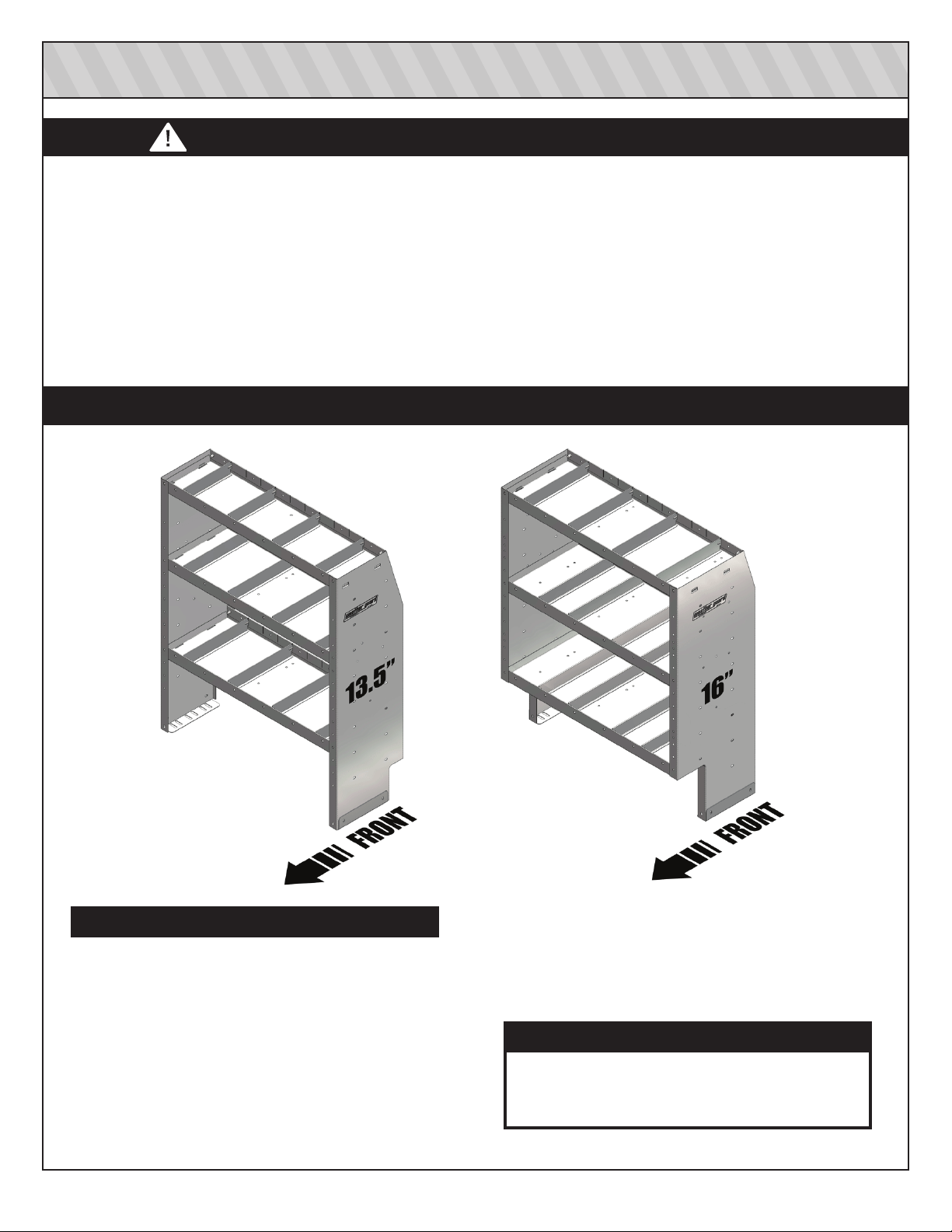
ATTENTION: 13.5” SHELF vs 16” SHELF NOTCH LOCATION
TOOLS REQUIRED
• Electric drill-driver or impact wrench
• Pencil or marker
• Rubber Mallet
• Center punch
• 1” hole saw
• Hack saw blade or sharp knife
• 3/8“ and/or 1/4” drive ratchet wrench
• 7/16” and 3/8“ sockets
• Drill bits: 1/8”, 3/8”
• Level
• Carpenter’s square
• Open end wrenches 7/16” and 9/16”
CAUTION
Be safe - always wear protective eyewear to
keep debris out of your eyes when installing
WEATHER GUARD Van Products.
2
®
Page 3
PLAN YOUR VAN SHELVING INSTALLTION
Bottom Shelf
(All Shelves)
CHEVY Explres s /
GMC Savana
CHEVY City Express/
NISSAN NV200
5
Bottom Shelf Spacing for Wheel Wells
6
5
4
3
2
1
Shelf Spacing for Shelf Doors Shelf Spacing for Cabinet Accessories
7
Van
Location
FORD Transit 4
FORD E-Series 4
FORD Transit Connect ANY
RAM Promaster 6
RAM Promaster City 6
NISSAN NV
Sprinter 4
8
5
4
1
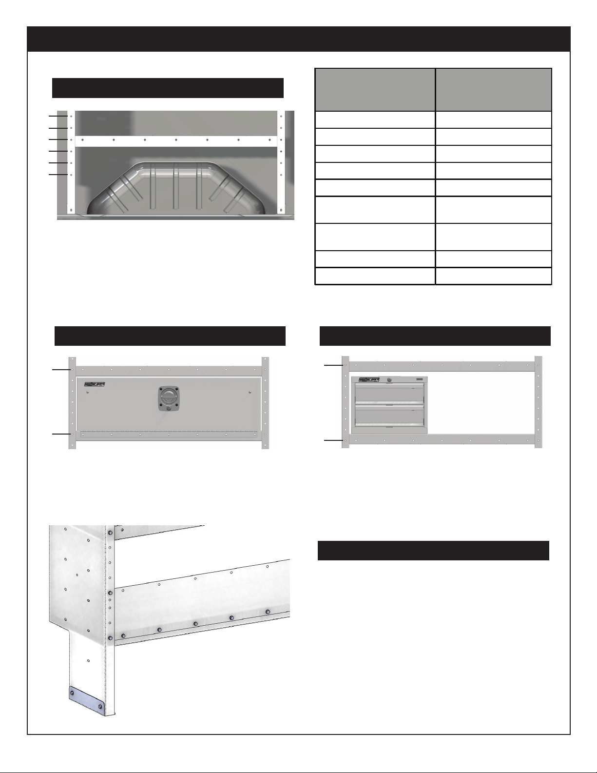
Allow seven mounting spots between
shelves for a shelf door accessory.
1
Allow eightmounting spots between shelves
for a shelf mounted cabinet accessory.
Back Panel Installation
Position back panels between shelf and end
panel edges to better secure back panel in
shelf unit, especially when using back panels
behind the top shelf. Use 1/4-20 x 3/4” bolts,
1/4“ flat washers, and nylon lock nuts.
3
Page 4

SHELF ASSEMBLY INSTRUCTIONS
STEP 1. With the end panels resting on the floor, insert the
top shelf into the bayonet clips. Mount the shelf
such that the square hole faces front of the shelf
unit.
STEP 2. Install the shelves working from the lowest shelf
upward using 1/4-20 x 3/4” bolts. Consider wheel
well height and clearance for tools or equipment
when placing lowest shelf.
STEP 3. Loosely assemble a mounting bracket to each end
panel using 1/4-20 x 3/4” bolts, 1/4“ flat washers,
and nylon lock nuts. Mount the bracket Under the
edge of the end panel.
STEP 4. Install dividers (optional).
*NOTE: Shelves need to be spaced seven(7) end panel holes
apart (bolt to bolt) for the door to fit correctly.
(13.5” deep shelf shown on the right.)
SECURE STORAGE ASSEMBLY INSTRUCTIONS
STEP 1. With the Secure Storage Module resting, place end
panel on each side of the Secure Storage Module
at the required position and bolt it in places using
four 1/4-20 x 3/4” bolts.
STEP 2. Insert the top shelf into the bayonet clips. Mount the
shelf such that the square hole faces front of the
shelf unit.
STEP 3. Carefully raise the shelf unit to an upright position
and bolt the Secure Storage Module in place with
four more 1/4-20 x 3/4” bolts.
STEP 4. Bolt down the top shelf using four 1/4-20 x 3/4” bolts.
Mounting bracket should overlap and support
end panel. It can be mounted on either side.
STEP 5. Loosely assemble a mounting bracket to each end
panel using 1/4-20 x 3/4” bolts, 1/4“ flat washers,
and nylon lock nuts. Mount the bracket under the
edge of the end panel.
STEP 6. Install dividers (optional).
*NOTE: All Secure Storage Modules are 16” deep.
Mounting brackets install the same way on all
shelving units.
4
Page 5

SHELF UNIT INSTALLATION INSTRUCTIONS
WEATHER GUARD Van Shelving provides vehicle mounting flexibility to customize the up-fit for the needs of
®
tradesmen and professionals.
STEP 1. Verify where the shelves are to be placed in the van, taking into account all equipment being installed, shelf
sizes, and the most convinient floor and wall mounting points. Check for clearance around wheel wells, tire
jack, fuel tank, fuel filler, brake lines, and wiring harness.
PLAN PLACEMENT AND VERIFY POSITION IN VAN BEFORE DRILLING!
STEP 2. Place assembled shelves in the van and check for alignment using a level and/or carpenter’s square.
STEP 3. WEATHER GUARD van shelving provides multiple points to attach wall mounting straps to the shelf unit.
®
Loosely pre-asemble and attach mounting straps to end panels now to make shelf positioning easier.
Mount two mounting angle brackets to one end of the mounting strap using a 1/4-20 x 3/4” bolt with a
washer and nylon lock nut. Attach mounting strap using one 1/4-20 x 3/4” bolt with a washer and nylon
lock nut.
It is important to make sure that the mounting straps are attached on the end panels perpendicular to the
van walls. The mounting strap needs to be bolted at two points at minimum where the strap and the end
panel meets. Attach the mounting strap to end panel using a exisintng obround hole such that the strap
can pivot and is long enough to reach the van wall. Use a 1/4-20 x 3/4” bolt with washer and a nylon lock
nut but do not tighten at this time.
5
Page 6

SHELF UNIT INSTALLATION INSTRUCTIONS
STEP 4. Mark floor and wall mounting locations. Two moungint bolts per bracket is recommended. Verify that
mounting locations will not puncture the fuel tank or break fuel lines, brake lines, and wiring harness.
STEP 5. Move the shelf unit out of the way and drill the floor mounting holes. Verify again that mounting locations do
not interfere with any of the aforementioned parts of the van. If the van has a floor liner mat, cut 1” diameter
holes using a hole saw to install blind fasteners directly to the sheetmetal floor.
STEP 6. Install blind fasteners in the floor. When shelf units mount next to each other, one mounting bracket can be
shared to simplify installation without sacrificing structural integrity. DO NOT USE BLIND FASTENERS IF
THERE IS A RISK OF THE BLIND FASTENER PUNCTURING A FUEL TANK. Instead, through-bolt to the
floor using 1/4-20 x 1-1/2“ bolt with a nylon lock nut and flat washers fon both sides of the floor.
- Place a drop of oil on the black oxide bolt before assembling as shown.
- Place the Blind Fastener in the hole and use a 7/16” wrench or socket
to tighten the bolt until the Blind Fastener is fully sedated.
- When setting the bolt, it will start out hard. As the Blind Fastener “bulbs”
out it will get easier, until it bottoms out or sets.
- Use a 9/16“ wrench to make sure the Blind Fastener and installation tool
do not turn during installation.
STEP 7. Reposition the assembled shelf unit and check for alignment. Mount shelf unit to floor. Use a washer and the
1/4-20 x 1-1/2” mounting bolts into the blind fasteners. Use floor spacers as required to level the shelf unit
ensuring a solid connection to the van floor. Wait until the shelf unit is attached to the walls before completely
tightening the floor mounting bolts.
*Note: Use mounting kit 9720-3-01 for Nissan NV.
6
Page 7

SHELF UNIT INSTALLATION INSTRUCTIONS
STEP 8. Finish installing the mounting straps by aligning then drilling additional hole for the second attachment point
mentioned in STEP 3. Use a 1/4-20 x 3/4” bolt with washer and a nylon lock nut. Mounting straps can be
trimmed or bent to get the best fit to the inside wall of the van.
Existing
obround
Drill here
Install middle mounting point when possible. You can bend the mounting strap to create a triangular
mounting to strengthen the shelf unit.
Triangluar Mount
Middle Mount
7
Page 8

SHELF UNIT INSTALLATION INSTRUCTIONS
STEP 9. Verify the wall mounting locations and install blind fasteners. Existing holes may be used to install blind
fasteners if they are located near the mounting straps. If not, they may still be used for ADDITIONAL
mounting points using extra mounting straps. We recommend using two mounting angles on the strap
joining two shelf units. One mounting foot can be shared between two shelf units.
Double blind fasteners MUST
be used on upper mounting
points on FORD vehicles and
is recommended on all other
vehicles.
STEP 10. Assemble a lock washer and a flat washer to each 1/4-20 x 1-1/4” mounting bolt, and loosely attach the
shelf unit to the blind fasteners in the van wall through the mounting angles. Once all brackets and
mounting bolts are in place, re-check for alignement and tighten all bolts to 24 in-lbs.
*Note: Some accessories, like shelf doors, back panels, and retainer lips may be easier to install prior to
installing the shelf unit in the van.
60“ x 16” shelf units include a center support bracket. It can be mounted in front of, or behind the
shelf unit. The support bracket does not need to be centered. Load on the shelf will need to be
reduced if the unsupported span exceeds 48” or if the support is not used.
8
Page 9

VAN SHELVING ACCESSORIES AND SERVICE PARTS
Part No. Part Name Descripon
Specialty shelf unit mounting kits speed installation by
uzing existing mounting features.
9503-3-01 Shelf Door, 36 in
9504-3-01 Shelf Door, 42 in
9505-3-01 Shelf Door, 52 in
9506-3-01 Shelf Door, 60 in
9603-3-02 Accessory Back Panel, 36 in
9604-3-02 Accessory Back Panel, 42 in
9605-3-02 Accessory Back Panel, 52 in
9606-3-02 Accessory Back Panel, 60 in
9703-3-02 Retainer Lip, 36 in
9704-3-02 Retainer Lip, 42 in
9705-3-02 Retainer Lip, 52 in
9706-3-02 Retainer Lip, 60 in
Shelf Doors and Back Panels help secure shelf
contents.
Retainer lips for mounng a shelf door at floor level
or keeping parts in place under shelf units.
9730-3-01 Shelf Support for 36 in high sh
9740-3-01 Shelf Support for 44 in high shelf units
9760-3-01 Shelf Support for 60 in high shelf units
9820 Bin Dividers, 10 in
9823 Bin Dividers, 13 in
9825 Bin Dividers, 13 1/2 in
9826 Bin Dividers, 16 in
8841 Shelf Mat for 13-1/2 in deep shelves
9832 Shelf Mat for 13 in deep shelves
9836 Shelf Mat for 16 in deep shelves
9720-3-01 Nissan NV floor mounting adapter kit
70221 Replacement Bolt Kit For Van Shelf End Panel
70222 Replacement Bolt Kit For Van Shelf Kit
70201 Replacement Shelf End Panel Cap
70202 Replacement Cam Handle Set
70203 Replacement Back Panel Fastener Kit
7601 T Bracket Shelf Unit Mounting Kit
7604 1/4 In Thick Aluminum Mounting Spacer Kit (50 Pcs)
70136 White touch-up paint (½ ounce brush tip)
886-1CN White aerosol touch-up paint (12 ounce aerosol)
954-1CN Red
7998-10PK 1/4 in Blind Fasteners kit, 10 pack
7998-20PK 1/4 in Blind Fasteners kit, 20 pack
7998-50BG 1/4 in Blind Fasteners kit, 50 pack
7998-100BG 1/4 in Blind Fasteners 100 pack
999-10PK 5/16 in Blind Fasteners kit, 10 pack
999-20PK 5/16 in Blind Fasteners kit, 20 pack
999-50BG 5/16 in Blind Fasteners kit, 50 pack
999-100BG 5/16 in Blind Fasteners 100 pack
aerosol touch-up paint (12 ounce aerosol)
elf units
Shelf supports increase the load capacity of Weather
Guard shelves.
Shelf mats and extra divider sets provide more
organizaon opons.
Van Shelving Replacement parts kits
9
Page 10

WARNING
This product can reduce the driver’s ability to clearly see roadways, vehicular or pedestrian traffic and other objects through the rear and
side windows of the vehicle, which can cause an accident. Extra precautions should be taken when driving a vehicle with this product. Make
all adjustments necessary to ensure maximum visibility, including but not limited to, changing mirror and seating positions. State and local
laws may prohibit obstruction of windows in a moving vehicle.
These instructions are to be followed using the parts and fasteners supplied for proper installation. Any modifications or improper installation
of this product will create a hazardous condition that could result in death, serious personal injury and/or property damage.
CAUTION
Prior to drilling, so as not to cut electric wires, fuel lines, brake lines, etc., check behind and underneath drilling and mounting locations. To keep
debris out of your eyes when checking the underside of the vehicle, or when drilling, always wear protective eye wear. Failure to heed this warning
will result in death or serious injury.
– NOTICE –
Any modification or unintended use of this product shall imediately void all manufacturers warranties. Manufacturer disclaims all liability for injuries
to persons or property resulting from any modification to, or unintended use of this product.
KNAACK LLC LIMITED LIFETIME WARRANTY FOR WEATHER GUARD® PRODUCTS
WEATHER GUARD® Products — Limited Lifetime Warranty
(Purchased on or after 1/1/2009)
®
Knaack LLC (the “Manufacturer”) warrants to the original purchaser only that WEATHER GUARD
(the “WEATHER GUARD
the WEATHER GUARD
terminates if the original purchaser transfers the WEATHER GUARD
What is Covered
All WEATHER GUARD
What We Will Do to Correct Problems
Subject to the limitations and exclusions described in this limited warranty, the Manufacturer will remedy defects in materials or workmanship by providing
one of the following remedies at its option and
®
GUARD
Product or (b) replacing the entire WEATHER GUARD® Product. In addition, the manufacturer may elect at its option, not to repair or replace the
WEATHER GUARD
be used toward the purchase of new WEATHER GUARD
What is Not Covered
This limite
No
This Limited Lifetime Warranty is the sole and exclusive warranty for WEATHER GUARD
alter this warranty or make any other warranty on behalf of Knaack LLC.
Noti
If the WEATHER GUARD
discovery of the nonconformity. In order to receive the remedies under this limited warranty, the warranty claim must describe the nature of the nonconformity, and
a copy of the original sales receipt, invoice, bill or other proof of purchase must accompany the claim. Repairs or modificatio ns made to the WEATHER GUARD
Product by ot
the owner ’s compliance with these required notification and repair procedures. Warranty claims must include reciprocal contact information and may be made via
certified mail to:
d warranty expressly excludes:
• Defects caused by normal wear and tear, cosmetic rust, scratches, accidents, unlawful vehicle operation, or modification to the product, or any types or
repair of a WEATHER GUARD
• Defects resulting from conditions beyond the Manufacturer’s control including, but not limited to misuse, overloading, or failure to assemble, mount or use
the WEATHER GUARD
made available to the original purchaser.
• Damage to the contents of the box or vehicle.
• TO THE EXTENT PERMITTED BY LAW, IN NO EVENT SHALL THE MANUFACTURER BE LIABLE FOR ANY INCIDENTAL, SPECIAL, INDIRECT,
OR CONSEQUENTIAL DAMAGES, INCLUDING ANY ECONOMIC LOSS, WHETHER RESULTING FROM NONPERFORMANCE, USE, MISUSE OR
INABILITY TO USE THE WEATHER GUARD
Other Express Warranty Applies
cation Pro cedures
her than the Manufacturer or its authorized agent will nullify this limited warranty. Coverage under this limited warranty is conditioned at all times upon
®
Product”) will be free from defects in material and workmanship from the date of purchase and continuing for the expected life time of
®
Product. A copy of the original sales receipt must be supplied to the Manufacturer at the time a warranty claim is made. This warranty
®
Products identified above that are purchased on or after January 1, 2009.
without charge to the original purchaser for parts or labor: (a) repairing the defective portion of the WEATHER
®
Product, but rather issue to the original purchaser a refund equal to the purchase price paid for the WEATHER GUARD® Product or a credit to
®
Product other than those authorized or provided by the Manufacturer.
®
Product in accordance with the Manufacturer’s written instructions or guidelines included with the WEATHER GUARD® Product or
®
Product does not conform with the terms of this limited warranty, the original owner must promptly notify the Manufacturer in writing upon
®
Product.
®
PRODUCT OR THE MANUFACTURER’S NEGLIGENCE.
®
Product to any other person.
Knaack LLC
ATTN: Warranty Claims
420 E. Terra Cotta Avenue Crystal Lake, IL 60014
Truck and Van Products
®
products. No employee, agent, dealer, or other person is authorized to
®
*24-0308*
If you have any questions, please call toll free at 1-800-456-7865
©2016 Knaack LLC
10
Part No. 24-0405 REV. B ECO 102731 04/16
 Loading...