

Page 1
JUMBO VAN SHELVING
INSTALLATION MANUAL
ATTENTION: PLEASE READ AND UNDERSTAND ALL INSTRUCTIONS AND WARNINGS BEFORE ASSEMBLING, INSTALLING OR USING THIS PRODUCT.
DANGER
Danger of explosion. Do not use this product for storing or
transporting flammables, explosives, hazardous materials, or
hazardous waste, such as containers of gasoline, solvents, gun
powder, dynamite, propane tanks, acetylene tanks and cutting
torches. This product is only intended and safe for use in storing
and transporting small tools, equipment and other similar materials.
Any modifications made to, or unintended use of this product,
could create a hazardous condition that can cause death, serious
personal injury or property damage.
Approximate Assembly and Installation Time:
60-80 min. (1 to 1.3 hours) depending on number of shelf
units and van equipment installation experience.
TOOLS REQUIRED
• Electric Drill
• Drill Bits: 13/32", 5/16", 1/8"
• Open End Wrenches: (2) 7/16", 9/16"
• 1" Hole Saw
E
WARNING
These instructions are to be followed using the parts and fasteners
supplied for proper installation. Any modifications or improper
installation of this product will create a hazardous condition that
can cause property damage, serious personal injury or death.
– NOTICE –
Any modification or unintended use of this product shall immediately
void all manufacturers warranties. Manufacturer disclaims all liability
for injuries to persons or property resulting from any modification
to, or unintended use of this product.
8380
8320
8332
8342
8352
#32-0162 #32-0162 #32-0163 #32-0183
8381
8383
8384
8390
8393
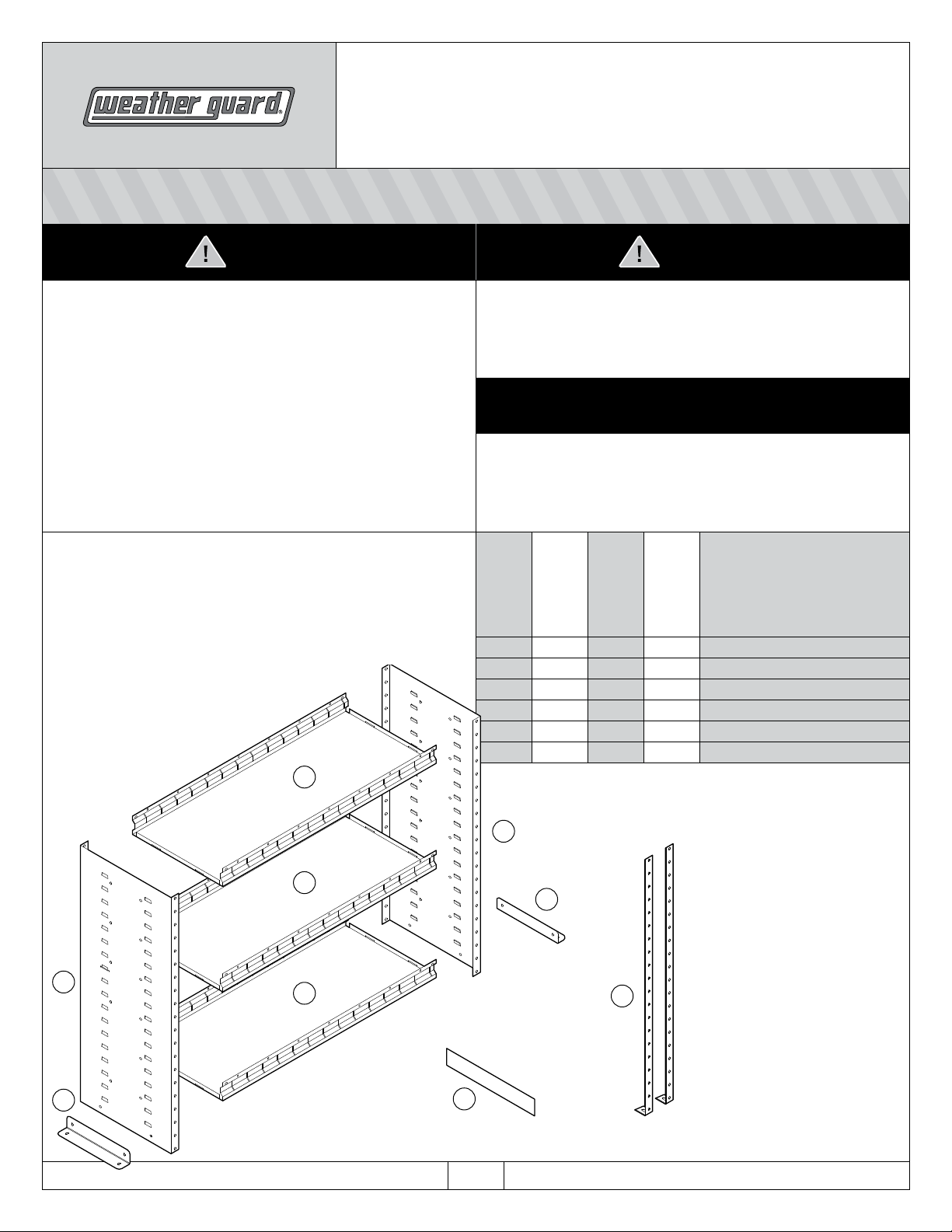
2 2 2 2 A Floor Mounting Brackets
0 0 2 0 B Center Supports
8 12 12 0 C Shelf Dividers
2 2 2 2 D End Panels
2 3 3 0 E Shelves
8385
8391
8394
8395
8345
8957
8958
8959
Parts List
Bolt Kit
D
E
A
D
A
E
C
PAGE 1IF YOU HAVE ANY QUESTI ONS, PLEASE CONTACT U S TOLL-FREE AT 1.800.4 56.7865 24-0245 R EV. A 07/06
B
Page 2
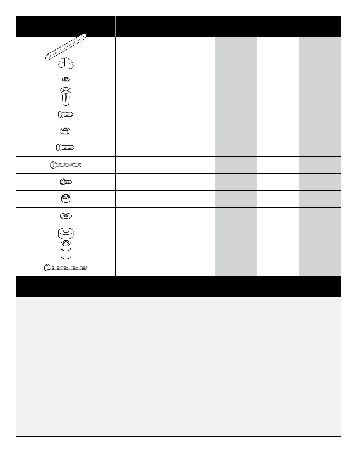
NOTE: Depending on your application you may end up
with extra hardware after installation is complete.
DESCRIPTION
Mounting Straps 3 3 3
Mounting Strap Angles 3 3 3
1/4" Lock Washers 4 4 4
1/4-20 Blind Fasteners 4 4 4
1/4-20 x 5/8" Hex Head Bolts 10 10 10
1/4-20 Serrated Nuts 12 12 0
1/4-20 x 3/4" Hex Head Bolts 7 13 7
1/4-20 x 1-1/4" Hex Head Bolts 4 6 4
1/4-20 x 1/2" Hex Head Screws 12 12 0
BOLT KIT #32-0162
QTY.
BOLT KIT #32-0163
QTY.
BOLT KIT #32-0183
QTY.
1/4-20 Nylon Lock Nuts 18 26 18
1/4" Flat Washers 18 22 18
Floor Mounting Spacers 4 6 4
Blind Fastener Installation Tool 1 1 1
1/4-20 x 2-1/4" Hex Head Black Bolt 1 1 1
KNAACK MANUFACTURING COMPANY LIMITED WARRANTY
This LIMITED WARRANTY is made by Knaack Manufacturing Company, 420 E. Terra Cotta Ave., Crystal Lake, Illinois to the original retail purchaser
of KNAACK® Products.
KNAACK MANUFACTURING COMPANY WARRANTS THAT KNAACK PRODUCTS WILL BE FREE FROM DEFECTS IN MATERIAL AND WORKMANSHIP
FOR A PERIOD OF THREE (3) YEARS FROM DATE OF PURCHASE BY THE ORIGINAL RETAIL PURCHASER.
If, before the expiration of the Warranty period, purchaser discovers that the KNAACK Product fails to fulfill the Warranty, purchaser shall contact Knaack
Manufacturing Company to make arrangements for an inspection of the product. If Knaack Mfg. Co. determines a defect exists, Knaack Mfg. Co. shall,
at its option and expense, repair or replace any defective part. All Warranty repairs shall be made by an authorized KNAACK Product dealer or Knaack
Mfg. Co. approved service company.
This Warranty shall not apply if the KNAACK Product has been subjected to misuse, abnormal service or handling, improper maintenance, or alterations
made by anyone other than a KNAACK Product dealer or a Knaack Mfg. Co. approved service company.
THE WARRANTY PRINTED ABOVE IS THE ONLY WARRANTY APPLICABLE TO THIS PURCHASE. ALL OTHER WARRANTIES, EXPRESS OR
IMPLIED, INCLUDING BUT NOT LIMITED TO THE IMPLIED WARRANTIES OF MERCHANTABILITY AND FITNESS FOR A PARTICULAR PURPOSE
ARE HEREBY DISCLAIMED.
KNAACK MANUFACTURING COMPANY SHALL NOT BE LIABLE FOR ANY INCIDENTAL OR CONSEQUENTIAL DAMAGES ARISING OUT OF
ANY BREACH OF THIS WARRANTY. NOR SHALL THE DAMAGES EXCEED THE RETURN AMOUNT OF THE PURCHASE PRICE PAID BY THE
ORIGINAL PURCHASER.
This Warranty is in lieu of all Warranties express or implied. The terms of this Warranty shall not be modified by any party, their successors or assigns.
This Warranty gives you specific legal rights, and you may also have other rights which vary from state to state.
PAGE 2IF YOU HAVE ANY QUESTI ONS, PLEASE CONTACT U S TOLL-FREE A T 1.800.456.7865 24-0245 R EV. A 07/ 06
Page 3

CAUTION WARNING
Prior to drilling, so as not to cut or puncture fuel tanks, fuel lines,
brake lines, electric wires, etc., check behind or underneath drilling
and mounting locations.
To keep debris out of your eyes when checking the underside of
the vehicle, or when drilling, always wear protective eyewear.
1 After determining shelf spacing, assemble
each Shelf to the End Panels by pushing the
Shelf down, with the End Panel tab entering
the pierced opening on the Shelf edge.
Fasten the Shelves to the End Panels using
four (4) 1/4-20 x 1/2" Hex Head Bolts and
1/4-20 Serrated Nuts.
All floor mounting bolts near the fuel tank area should be installed
from the underside of the vehicle, to guard against the fuel tank
being punctured in the event of a collision. This would mean not
using Blind Fasteners in this area. Holes in this area should be 5/16".
Ensure ample space in roof ribs and sidewall ribs for mounting
screws so as not to puncture exterior roof or wall.
2 Attach the Floor Mounting Brackets to both
ends of the unit using four (4) 1/4-20 x 3/4"
Hex Head Bolts, 1/4" Flat Washers and
1/4-20 Nylon Lock Nuts.
NOTE: Floor Mounting Brackets can be
installed on the outside or inside ends of the
units. When installing two units side by side
or connecting to a Bulkhead, only one Floor
Mounting Bracket is required and should be
installed inside.
If installing more than one shelf unit, holes
in the end panels are provided for throughbolting into the next unit for greater rigidity.
PAGE 3IF YOU HAVE ANY QUESTI ONS, PLEASE CONTACT U S TOLL-FREE A T 1.800.456.7865 24-0245 R EV. A 07/ 06
Page 4

3 Place the unit into your selected position
in the van, as close to the wall as possible.
Mark the four floor mounting holes where
the Floor Mounting Bracket comes in
contact with the floor ribs.
NOTE: 60" & 69" SHELF UNITS: Center
Support Legs have been added to these
units to strengthen these shelves because
of their length. (Go to step 6). If Center
Supports are needed, then mark their floor
mounting holes also. The Center Support
can face towards the unit or away from the
unit and should also contact the floor rib.
Remove the unit and pre-drill the floor
mounting locations with an 1/8" drill bit, then
re-drill the hole with a 5/16" drill bit. If there
is a floor mat, then Floor Mounting Spacers
are required. Cut the floor mat around the
5/16" holes with the 1" hole saw, allowing
Floor Mounting Spacers to rest against the
metal floor. DO NOT DRILL THROUGH
THE VAN FLOOR WITH THE HOLE SAW.
4 Move the unit back into position. Fasten unit
to van floor using four (4) 1/4-20 x 1-1/4"
Hex Head Bolts, 1/4" Flat Washers, Floor
Mounting Spacers (if applicable), second set
of 1/4" Flat Washers and 1/4-20 Nylon Lock
Nuts. (See example bolting solutions below).
NOTE: One (1) Blind Fastener and Lock
Washer have been provided in case throughbolting is impossible due to heat shields, floor
channels, fuel lines, etc. If Blind Fastener
installation is necessary, redrill the 5/16"
mounting holes with 13/32" drill bit. See
INSTALLATION INSTRUCTIONS FOR BLIND
FASTENERS on page 6.
NOTE: The floor bolting
solution could be a variation
on any of these three examples
with or without the floor mat.
TOP DOWN INSTALLATION THROUGH
FLOOR MAT AND VAN FLOOR
BOTTOM UP INSTALLATION THROUGH
FLOOR MAT AND VAN FLOOR
PAGE 4IF YOU HAVE ANY QUESTI ONS, PLEASE CONTACT U S TOLL-FREE A T 1.800.456.7865 24-0245 R EV. A 07/ 06
BLIND FASTENER INSTALLATION THROUGH
FLOOR MAT AND VAN FLOOR (SEE PAGE 5)
Page 5

5 Three (3) Mounting Straps and Mounting
Strap Angles are provided. The Mounting
Straps can be bent to any shape and/or
used with the Mounting Angles. The
Mounting Straps should be attached to the
upper portion of the shelf unit in a manner
that would minimize movement of the unit
both front to rear and side to side. Attach
the Mounting Straps to the shelf unit through
existing holes (or drill new holes using a
5/16" drill bit) and fasten with three (3) 1/420 x 5/8" Hex Head Bolts and 1/4-20 Nylon
Lock Nuts.
Fasten the other end of the Mounting
Straps by installing two to three (2-3) Blind
Fasteners in the wall or wall ribs at the
Mounting Strap locations by pre-drilling
1/8" holes and then re-drill the holes with
a 13/32" drill bit. Set the Blind Fasteners
in the holes per the INSTALLATION
INSTRUCTIONS FOR BLIND FASTENERS
on page 6.
Realign the Mounting Straps/Mounting Strap
Angles on top of the Blind Fasteners and
secure them to the wall or wall rib using two
to three (2-3) 1/4-20 x 3/4" Hex Head Bolts
and 1/4" Lock Washers.
INSTALLATION IS COMPLETE.
6 60" & 69" SHELF UNITS: Fasten the
Support Leg(s) in the center of the Shelf
using three (3) 1/4-20 x 3/4" Hex Head
Bolts, and 1/4-20 Nylon Lock Nuts.
Return to step 3.
NOTE: If installing doors on these units,
the Support Leg will need to be installed
off-center on the shelf. Positioning of the
Support Leg can easily be found by holding
the door in position on the shelf. The
notched out area of the hinge is where
to locate the Support Leg.
A second leg can also be fastened to the
back of the unit.
NOTE: The Center Support Leg may need
to be trimmed depending on application. If
the Support Leg is cut, remove burrs and
apply paint.
PAGE 5IF YOU HAVE ANY QUESTI ONS, PLEASE CONTACT U S TOLL-FREE A T 1.800.456.7865 24-0245 R EV. A 07/ 06
Page 6

7 Insert the Shelf Dividers into the shelf slots.
NOTE: The side panels of the units have
pre-punched holes conveniently located for
installation of accessory items or to fasten
to other shelf units for additional strength.
Extra 1/4-20 x 5/8" bolts and lock nuts have
been provided in the bolt kit for this purpose.
WARNING
Prior to drilling, so as not to cut or puncture fuel tanks, fuel lines,
brake lines, electric wires, etc., check behind or underneath
drilling and mounting locations.
CAUTION
To keep debris out of your eyes when checking the underside of
the vehicle, or when drilling, always wear protective eyewear.
Place a drop of oil on the black oxide bolt before assembling as
shown on right. Place the Blind Fastener in the hole and use a
7/16" wrench to tighten black hex bolt until the Blind Fastener is
fully seated. When setting black hex bolt, it will start out hard.
As the Blind Fastener “bulbs” out it will get easier, until it bottoms
out or sets. Make sure the Blind Fastener and Installation Tool
do not turn during installation.
INSTALLATION INSTRUCTIONS FOR BLIND FASTENERS
7/16” Wrench
(Or 7/16” Socket)
Black Oxide Bolt
Flat Washer
9/16” Wrench
Installation Tool
Blind Fastener
WEATHER GUARD® products are protected by one or more of the following trademarks: U.S. 842268, 1661625, 1663369, 2228051, 2362167; Canada - 282725; U.K. - 1400720; N.Z. - 296049; Aus.- 761964
PAGE 6IF YOU HAVE ANY QUESTI ONS, PLEASE CONTACT U S TOLL-FREE A T 1.800.456.7865 24-0245 R EV. A 07/ 06
 Loading...