

Page 1
ASSEMBLY AND INSTALLATION INSTRUCTIONS
BED RAT® Sliding Platform Model 3100 3200 3300 3400
IMPORTANT
BEFORE YOU BEGIN
DANGER
Read these instructions and warnings
completely before installing.
WARNING
These instructions are to be followed for
proper installation of this product. Improper
installation or any modifications made to this
product, could create a hazardous condition
that can cause serious personal injury or
property damage.
Approximate Assembly and Installation time:
5 hours per unit (5.0 hrs.)
Depending on Van equipment
installation experience.
Danger of explosion. Do not use this product
for storing or transporting flammables, explosives, hazardous materials, or hazardous
waste, such as containers of gasoline, solvents, gun powder, dynamite, propane tanks,
acetylene tanks, cutting torches and gas
powered equipment. This product is only intended and safe for use in storing and transporting small tools, equipment and other
similar materials. Any modifications made
to, or unintended use of this product, will
create a hazardous condition that will cause
death, serious personal injury or property
damage.
- Load Rating 750 lbs.
evenly distributed
TOOLS REQUIRED
Electric Drill
3/16", 5/16", 3/8" and 1/2" Drill Bits
1/2" Open or Box End Wrench
7/16" Open or Box End Wrench (2)
9/16" Open or Box End Wrench
Part No. 24-3201 REV. H ECN 5282 03/13
Page 2
BOLT KITS - The following are provided with each
model:
Model 3100 3300
3200 3400
Description
Bolt Kit 32-3200 32-3400
8 12 5/16-18 x 1-1/2" Bolt, Hex
22 22 5/16-18 x 1-1/4" Carriage Bolt
4 4 1/4-20 x 5/8" Bolt, Hex
4 4 1/4-20 Whiz Nut
12 16 5/16" Flat Washer
8 12 5/16-18 Blind Fastener
1 1 5/16-18 x 2-1/4" Blk. Ox. Bolt
8 12 5/16 Lock Washer
22 22 5/16-18 Whiz Nut
1 1 Installation Tool
2 2 3/8 x 4 Stop Pin
4 4 5/16-18 Nylon Lock Nut
4 0 Spacers
Left Side Retainer
3100 p/n 20-3620
3200 p/n 20-3603
3300 p/n 20-3605
3400 p/n 20-3607
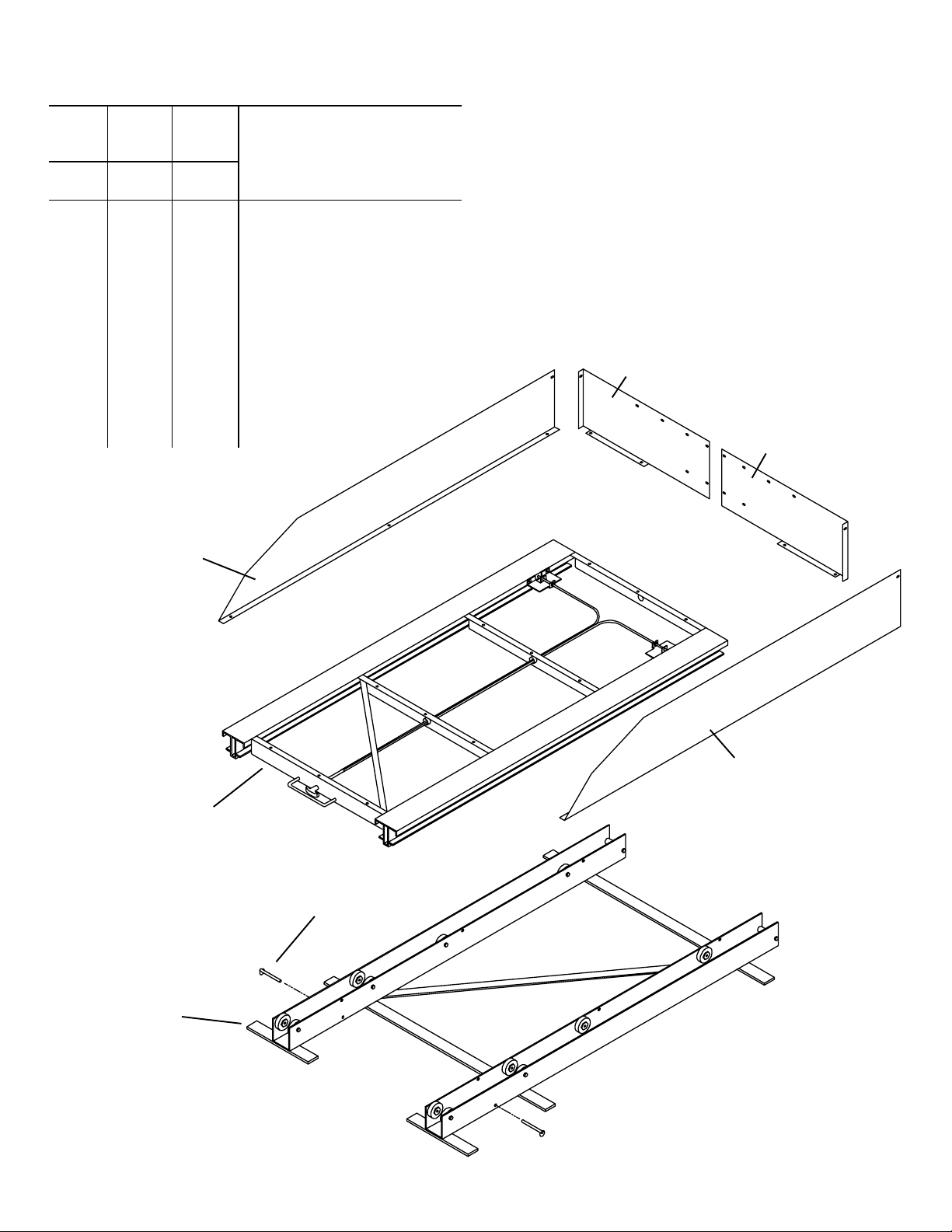
PARTS LIST
1 Deck Assembly
1 Base Assembly
1 Left End Retainer
1 Right End Retainer
1 Left Side Retainer
1 Right Side Retainer
Left End Retainer
p/n 20-3609
Right End Retainer
p/n 20-3608
Deck Assembly
3100 p/n 25-3101
3200 p/n 25-3201
3300 p/n 25-3301
3400 p/n 25-3401
Base Assembly
3100 p/n 25-3100
3200 p/n 25-3200
3300 p/n 25-3300
3400 p/n 25-3400
2
Right Side Retainer
3100 p/n 20-3619
3200 p/n 20-3602
3300 p/n 20-3604
3400 p/n 20-3606
3/8" x 4"
Stop Pin
Figure 1. Parts Identification
Page 3

ASSEMBLY INSTRUCTIONS for
Models 3200 3300 3400
(see back page for Model 3100)
NOTE: To prevent rust from occurring, touch-up any
drilled holes.
1. Place the Base Assembly centered in the vehicle. See
Figure 1. for correct location. Close the tailgate or doors to
make sure the unit is properly placed. If installing a Model
3100 out a van side door(s), make sure to take into account
the door opening width. If installing a bulkhead, this should
be done first.
2. Mark hole locations on the mounting bars, centering the
holes on the bars and on the top portion of the floor ribs if
possible. If it is not possible, four Spacers have been provided to fill the space between the mounting bars and the
lower part of the floor ribs. NOTE: Twelve holes are required
for Models 3300 & 3400, eight holes for Model 3200 (see
Figure 2. for mounting holes) and four for Model 3100 (see
Figure 3.). Drill through the mounting bar and the floor at
one rear location, and insert a 5/16-18 x 1-1/2" Hex Hd. Bolt
into the hole. Drill one front mounting bar location, and insert
a bolt. Drill the rest of the mounting bar/floor holes.
WARNING
CAUTION
To keep debris out of your eyes when checking
the underside of the vehicle, or when drilling,
always wear protective eyewear.
WARNING
Prior to drilling, so as not to cut or puncture fuel
tanks, fuel lines, brake lines, electrical lines, etc.,
check under vehicle for locations.
All floor mounting bolts near the gas tank area
should be installed from the underside of the vehicle, to guard against the gas tank being punctured in the event of a collision. This would mean
not using Blind Fastener in this area. Holes drilled
in this area should be 3/8".
3. Remove the Base Assembly and re-drill the floor holes
using a 1/2" drill bit.
2" For most Pickups
and all Vans
No Holes
Required
Inside edge of
tailgate or van
doors
Figure 2. Base Assembly marking/drilling (Model 3400 shown)
3/8" Hole
1/2" Hole
3
Page 4

5/16 Flat
Washer
5/16-18 x 1-1/2"
Hex Hd. Bolt
5/16 Lock
Washer
Figure 3. Model 3100 marking/drilling
4. Install Blind Fastener in the floor holes. See the Blind Fastener installation instructions on the back page. Replace the
Base Assembly in the vehicle and fasten it to the floor (see
Figure 4.).
5. To determine the size of the deck for pickups, the width
must clear between the wheel wells, and the length must be
just short of the inside length of the bed with the tailgate
closed. For vans, the width must clear not only the wheel
wells, but also any shelving or cabinetry fastened to the
sides of the van and fit out the rear doors. The length must
be just short of the inside length of the load area with the
doors closed. In either case, the size of the deck may be
considerably wider than the width of the bed rails, depending
on the space available. We suggest using 3/4" plywood that
is 2" less than the inside length of the pickup bed. In full size
vans, the width should be 1" less than the inside dimension
of the rear doors when fully open.
Mounting
5/16-18 Whiz Lock Nut
(12 places)
(6 places Model 3100)
Angles
Spacer (used only if
mounting through
the lower part of the
floor ribs as shown)
Figure 4. Fastening
6. Lay the decking material across two sawhorses. With the
help of another person, place the Deck Assembly upside
down on the deck material, 1" from the rear edge, and centered side to side. Using the Deck Assembly mounting angle
holes as a drilling template, drill 5/16" holes through the
deck material. Bolt the Deck Assembly to decking material
(see Figure 5.).
Installed
Blind
Fastener
Plywood should
extend 1" past
upper unit.
5/16-18 x 1-1/4"
Carriage Bolt
(12 places)
(6 places Model 3100)
4
Figure 5. Decking drilling and fastening
Page 5

7. With the Deck Assembly fastened to the decking material
and still upside down, place a Side Retainer lip on the decking, flush with the front of the decking. Mark the Side Retainer mounting holes. Repeat this for the other Side
Retainer. Place a Front Retainer on the decking at the front,
with the flange butted up to the decking side. Mark the Front
Retainer mounting holes. Repeat this for the other Front Retainer. Drill all marks with a 5/16" drill bit. Bolt the Side and
Front Retainers to the Deck Assembly. Bolt the Side and
Front Retainers together at the corners. The Front Retainers
have slotted holes at the center that will align to bolt them
together if using a decking with a width of 28", 30", 32", 35",
39", 40", 44" or 48". If using a decking with a non-standard
width, it will be necessary to drill a set of 5/16" holes to fasten the Front Retainers together. Bolt the Front Retainers
together (see Figure 6.).
8. With the help of another person, upright the Deck Assembly and slide it into the Base Assembly while holding the
black release handle out. Install the two 3/8" x 4" Safety
Stop Pins in the Base Assembly (see Figure 1.).
WARNING
Both safety stop pins must be installed in the
lower base to keep the upper deck unit from
rolling off the lower base unit, which could result
in serious personal injury or property damage.
5/16" Holes
(10 places)
5/16-18
Whiz Nut
(10 places)
5/16-18 x 1-1/4"
Carriage Bolt
(10 places)
1/4-20 x 5/8"
Hex Head Bolt
(4 places)
1/4-20 Nylon
Lock Nut
(4 places)
Figure 6. Side and End Retainer drilling and fastening
5
Page 6

INSTALLATION PROCEDURE USING BLIND FASTENERS
WARNING
Prior to drilling, so as not to cut
or puncture fuel tanks, fuel
lines, brake lines, electrical
wires, etc., check under vehicle
for locations.
Place a drop of oil on the
black oxide bolt before
assembling as shown on
right. Place the Blind Fastener in the hole and use
a 1/2 or 7/16 wrench to
tighten black hex bolt until
the blind fastener is fully
seated. When setting
black hex bolt, it will start
out hard. As the Blind
Fastener bulbs out it will
get easier, until it bottoms
out or sets. Make sure the
Blind Fastener and Installation Tool do not turn during installation.
Black
Oxide
Bolt
Flat
Washer
9/16
Wrench
Installation
Tool
Blind
Fastener
- NOTICE -
Any modification or unintended use of this product shall immediately void all manufacturers warranties.
Manufacturer disclaims all liability for injuries to persons or property resulting from any modification to, or
unintended use of this product.
WEATHER GUARD® products are protected by one or more of the following trademarks:
U.S. - 842268, 1661625, 1663369, 1840451, 1901674, 2228051, 2362167; Canada - 282725; U.K. - 1400720; N.Z. - 296049 other trademarks pending.
Knaack LLC
ATTN: War
0 E. Terra Cotta Avenue
42
Crystal Lake, IL 60014
If you have any questions, ple
ranty Claims
ase call toll free at 1-800-456-7865.
©2013 Knaack LLC
Part No. 24-3201 REV. H ECN 5282 03/13
 Loading...