

Page 1
MODEL 283 EZ-GLIDE™SYSTEM
8' HIGH CUBE VAN DRIVER SIDE
ALUMINUM DROP DOWN LADDER RACK
–ATTENTION–
Read and understand all instructions and warnings before operating or using this product.
WARNING
This product is only intended and only safe for transporting ladders. It is the responsibility of the user to secure these
materials to the rack before transporting.
Ladders must be secured per ANSI standard A142.2-1990 paragraph 8.4.4. Ladder damage will occur from road shock
and vehicle vibration if the ladder is not properly secured to the ladder rack. Bouncing and side to side motion of an
improperly secured ladder will cause wear and weaken the ladder. Using a damaged ladder could lead to structural collapse resulting in serious injury or death. Place ladder in a raised position before transporting. Driving with rack in lowered
position may cause serious injury or damage to vehicle, ladder, rack or persons.
–NOTICE–
Any modification or unintended use of this product shall immediately void all manufacturers warranties. Manufacturer disclaims all liability for injuries to persons or property resulting from any modification to, or unintended use of this product.
CAUTION
Never load your rack to exceed the safe capacity of your vehicle. Heavy loads when carried high can dangerously alter the
center of gravity.
Loads should be approximately centered front to rear. Failure to do this will cause damage to the vehicle roof. Long loads
that extend out the rear of the vehicle will prevent the rear hatch from fully opening and cause damage if attempted.
ASSEMBLY INSTRUCTIONS
TOOLS REQUIRED
• Open or Box End Wrench
9/16" - 1/2" - 7/16"
• 3/8" Drive Socket
9/16" - 1/2" - 7/16"
• 3/8" Drive Ratchet
• Phillips Screwdriver (Large)
• Needle Nose Pliers
• 3/8” Drive Torque Wrench (in. lbs.)
• Tape Measure
• Flat Screwdriver (Small)
• Electric Drill
• 5/16" Drill Bit
PARTS LIST
• Drive Shaft/Handle Assembly
• Lower Handle Section
• Upper Handle Section
• Cylinder
• Front Drive T
• Center Drive Tube
• 2 Ladder Supports
• 2 Ladder Stops
• 4 -Mounting Bases
• 2 -Mounting Tubes
• 2 - Black Plastic Bushings
• 2 - White Plastic Bushings
• Tube E-6000 Sealant
• 15-1" Dia. Vinyl Hole Covers
• Front Cross-Member Assembly
• Rear Cross-Member Assembly
• 1 - Tube Loctite 290
See Page 2
ube
120 min. per unit (2 hrs.) depending on van equipment and installer experience.
Read these instructions and warnings completely before installation.
Check these kits to be sure the following parts are included.
1 HRR ROTATION KIT:
2 3/8-16 x 2-1/4" Hex Hd. Bolt
2 3/8-16 Nylon Lock Nut
7 3/8" Flat Washer
4 5/16-18 x 2" Hex Hd. Bolt
10 5/16-18 Nylon Lock Nut
16 5/16" Flat Washer
1 5/16-18 x 4-1/2" Hex Hd. Bolt
1 5/16-18 x 1" Hex Hd. Bolt
1 Aluminum Bushing
1 Clevis Pin (1")
1 Clevis Pin (1-1/2")
1 Cotter Pin
1 Bushing Lubricant Tube
2 5/16-18 x 2-1/2" Phillips Flat Hd.
Screw
2 5/16-18 x 2-3/4" Hex Hd. Bolt
Approximate assembly and Installation time:
IMPORTANT BEFORE YOU BEGIN
HARDWARE KITS
See Page 3
1 HRR ROOF BASE KIT:
4 5/16-18 x 4" Hex Hd. Bolt
8 5/16-18 x 1-1/4" Hex Hd. Bolt
12 5/16-18 Nylon Lock Nut
8 5/16" Flat Washer
8 5/16” Rubber Washer
8 1-1/2” Fender Washer
8 Rubber Pads
8 3/8” Flat Washer
1
Part No. 24-0137 REV. E ECN 5315 05/13
Page 2
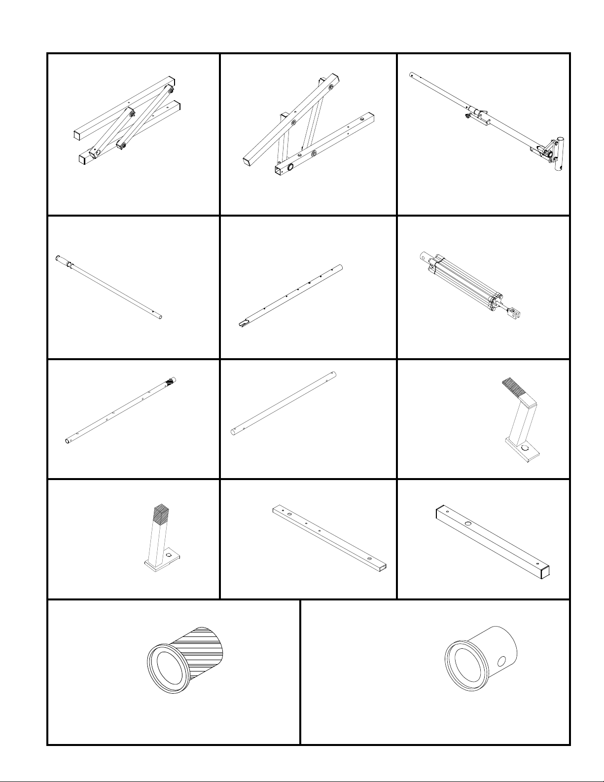
Front Cross-Member Assembly
Qty. 1
Rear Cross-Member Assembly
Qty. 1
Driveshaft/Handle Assembly
Qty. 1
Lower Handle Section
Qty. 1
Upper Handle Section
Qty. 1
Cylinder
Qty. 1
Black Plastic Bushings
Qty. 2
White Plastic Bushings
Qty. 2
Front Drive Tube
Qty. 1
Center Drive Tube
Qty. 1
Ladder Supports
Qty. 2
Ladder Stops
Qty. 2
Mounting Bases
Qty. 4
Mounting Tubes
Qty. 2
3
2
Page 3
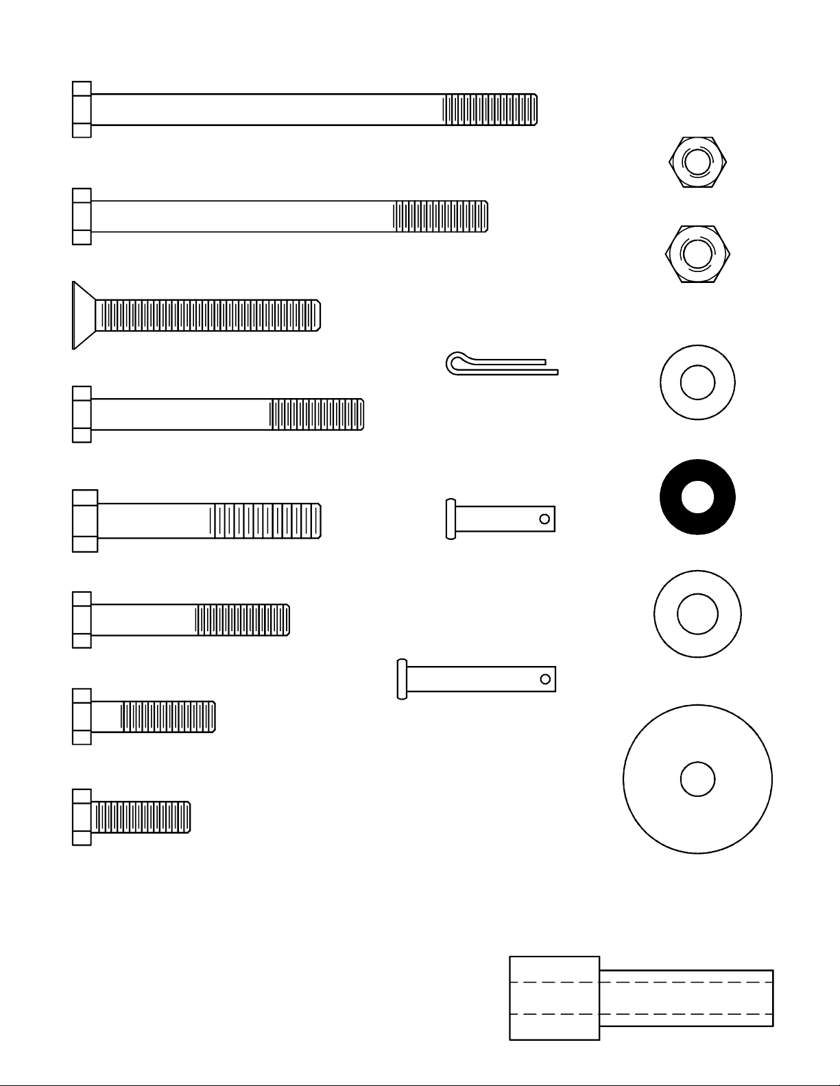
FASTENER CHART
5/16-18 x 4-1/2" Hex Hd. Bolt
3/8-16 x 2-1/4" Hex Hd. Bolt
5/16-18 x 2-3/4" Hex Hd. Bolt
5/16-18 x 4" Hex Hd. Bolt
5/16-18 x 2-1/2" Phillips Flat Hd. Screw
Aluminum Bushing
Cotter Pin
Clevis Pin (1")
Clevis Pin (1-1/2")
5/16-18 Nylon Lock Nut
3/8-16 Nylon Lock Nut
3/8" Flat Washer
5/16-18 x 1" Hex Hd. Bolt
5/16-18 x 1-1/4" Hex Hd. Bolt
5/16" Flat Washer
5/16-18 x 2" Hex Hd. Bolt
5/16" Rubber Washer
1-1/2" Fender Washer
3
Page 4
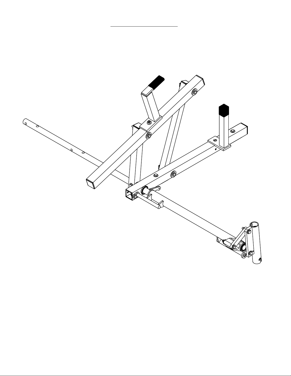
REAR ROTATION ASSEMBLY
5
4
Page 5
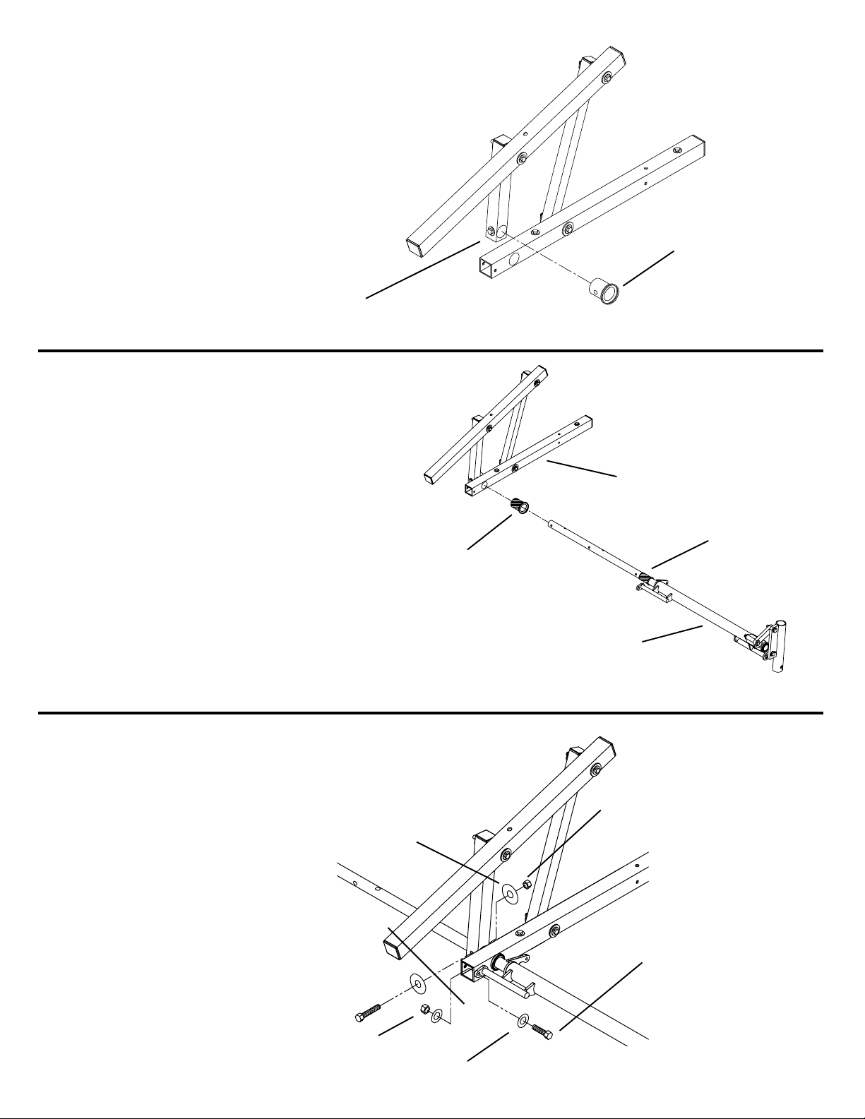
STEP 1
Slide a White Plastic Bushing (A)
into the Pivot Arm (B) as shown.
(A)
(B)
STEP 2
Use the supplied lubricant and coat the pre-assembled
Black Plastic Bushing (A). Insert the Driveshaft/Handle
Assembly (B) into the larger Black Plastic Bushing (C)
in the Rear Cross-Member Assembly (D) and through the
White Plastic Bushing in the Pivot Arm (Step 1) so that the
black bushings are fully seated.
(B)
(C)
(D)
STEP 3
Align holes in the Pivot Arm, White Plastic Bushing, and
Rear Drive Tube. Install the 3/8-16 x 2-1/4" Fastener. Next
install the 5/16-18 x 1" Fastener as shown.
* 3/8-16 x 2-1/4"
Hex Hd. Bolt
(A)
5/16-18 x 1"
Hex Hd. Bolt
3/8-16 Nylon
Lock Nut
(2) 3/8"
Flat Washer
5/16-18 Nylon
Lock Nut
(2) 5/16"
Flat Washer
NOTE: Tighten all marked (*)
fasteners to 200 in. lbs.
6
5
Page 6
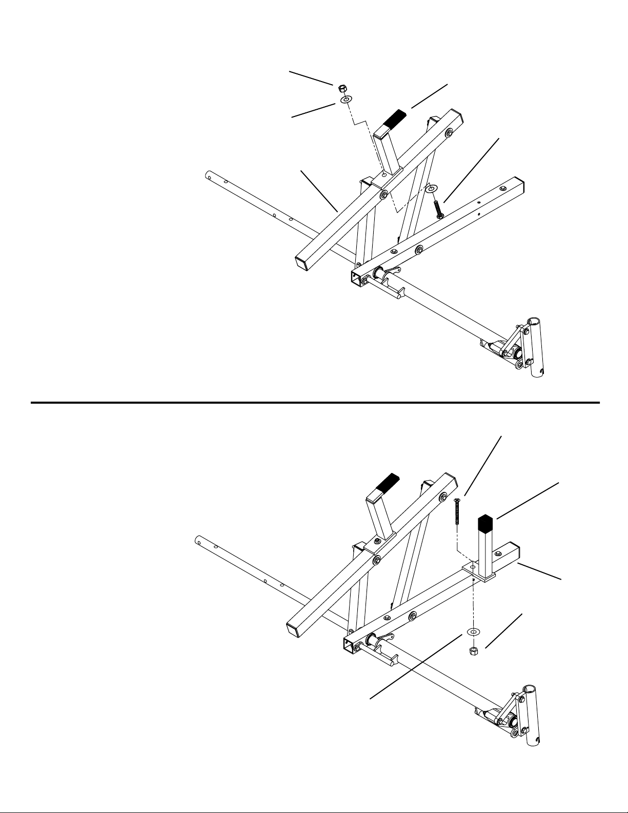
STEP 4
P
lace the Ladder Support (A) on top of
the Connecting Tube (B) and install the
5/16-18 x 2-3/4" Fastener.
(A)
(B)
5/16-18 x 2-3/4"
H
ex Hd. Bolt
(
2) 5/16" Flat
Washer
5/16-18 Nylon
Lock Nut
STEP 5
Place the Ladder Stop (A) on top of the
Cross-Member (B) and install the 5/1618 x 2-1/2" Fastener (Flat Hd. Screw).
(A)
(B)
5/16-18 x 2-1/2"
Flat Hd. Screw
5/16" Flat
Washer
5/16-18 Nylon
Lock Nut
6
Page 7

FRONT ROTATION ASSEMBLY
8
7
Page 8

S
TEP 6
Slide a White Plastic Bushing (A)
i
nto the Pivot Arm (B) as shown.
(
A)
(B)
STEP 7
Use the supplied lubricant and coat the pre-assembled
Black Plastic Bushing (A). Insert the Front Drive Tube (B)
into the larger Black Plastic Bushing (C) in the Front CrossMember Assembly (D) and through the White Plastic Bushing in the Pivot Arm (Step 4) so that the black bushings are
fully seated.
(A)
(B)
(C)
(D)
STEP 8
Align holes in the Pivot Arm, White Plastic Bushing, and
Front Drive Tube. Install the 3/8-16 x 2-1/4" Fastener.
* 3/8-16 x 2-1/4"
Hex Hd. Bolt
(2) 3/8" Flat
Washer
3/8-16 Nylon
Lock Nut
NOTE: Tighten all marked (*)
fasteners to 200 in. lbs.
9
8
Page 9

STEP 9
Place the Ladder Support (A) on top of
t
he Connecting Tube (B) and install the
5/16-18 x 2-3/4" Fastener.
(A)
(B)
5/16-18 x 2-3/4"
Hex Hd. Bolt
(
2) 5/16"
Flat Washer
5/16-18 Nylon
Lock Nut
STEP 10
Place the Ladder Stop (A) on top of the Cross-Member (B)
and install the 5/16-18 x 2-1/2" Fastener (Flat Hd. Screw).
(B)
5/16-18 x 2-1/2"
Flat Hd. Screw
5/16" Flat
Washer
5/16-18 Nylon
Lock Nut
(A)
9
Page 10

Cotter Pin
Clevis Pin
NOTE: Turn the Flow Control
counter clockwise to release
pressure. Adjust Flow Control Screw Per Instruction Decal On Handle Tube after
final assembly and installation.
(3) 3/8" Flat
Washer
5/16-18 x 4-1/2"
Hex Hd. Bolt
(A)
STEP 11
I
nsert Aluminum Bushing (A) into Rear
Cross-Member (B). Attach back of Cylinder (C)
to crossmember by installing 5/16-18 x 4-1/2"
Fastener. NOTE: After installing Bolt, apply
Loctite 290 to threads, then install the nut.
(C)
STEP 12
Attach front of Cylinder as shown. Bend over
Cotter Pin after inserting it through Clevis Pin.
5/16-18 Nylon
Lock Nut
(B)
CYLINDER INSTALLATION
11
10
Page 11

U
SE THESE HOLES FOR DESIRED LENGTH
8'
5
'
6'
7'
Front Pivot Arm
Rear Pivot Arm
S
TEP 13
Determine the length of rack you need.
FRONT TO REAR DRIVE TUBE ASSEMBLY
STEP 14
Locate desired front to rear length (5' or 6' or 7' or 8') and install
5/16-18 x 2" Fasteners (Tighten fasteners to 200 in. lbs.)
(4) 5/16-18
Nylon Lock
Nut
(8) 5/16" Flat
Washer
(4) 5/16-18 x 2"
Hex Hd. Bolt
STEP 15
Cover any exposed holes on Front and Rear Drive Tubes
with the 1" Dia. Vinyl Hole Covers
STEP 16
Seal the ends of the Center Drive Tube, the four 5/16-18 Fasteners, and the two 3/8-16 Fasteners with the tube of sealant supplied.
11
Page 12

VEHICLE MOUNTING PROCEDURE
12
Page 13

Unit will need to be placed on roof in a
position where the handle will be between 3" - 6" behind van. There are a
few preliminary steps you need to take
t
o make sure you use the correct holes
in mounting base. THIS RACK WAS
DESIGNED TO FIT VANS WITH
ROOF RIBS SPACED 24" APART. IF
YOUR VAN DOES NOT HAVE THIS
SPACING, YOU MUST SUPPLY
PROPER REINFORCEMENT ON INSIDE OF VEHICLE.
3" - 6"
STEP 17
Place a Mounting Base up on roof with
the two large holes facing up. These
two holes will be used to mount to the
roof ribs. One of the three small holes
will be used to mount the rotation kit to
the Mounting Base.
22-1/2" - 25-1/2"
STEP 18
Line up large holes so they are centered on roof ribs closest to the back of
the van. To get proper handle clearance of 3" to 6" from the back of van,
you will need to locate one of the small
holes so that it is between 22-1/2" to
25-1/2" from hole to back of the van
(See Illustration).
It may be necessary to rotate mounting
base so a small hole is in that range.
Roof Ribs
Mounting Base
Large
h
oles
Small
holes
Might have to flip
ends to get needed
dimension
STEP 19
After you have found the correct small
hole, remove Mounting Base from roof
and attach rear end of Rotation Kit to
the Mounting Bases using 5/16-18 x 4"
long Hex Hd. Bolt. Flat Washer and Nylon Lock Nut will mount through large
hole on bottom, onto bolt.
(2) Mounting Base
(2) 5/16-18 x 4" Hex
Hd. Bolt
(2) 5/16-18 Nylon
Lock Nut
(2) 3/8 Flat Washer
Back of van
Mounting Tube
13
Page 14

STEP 20
Determine what small hole to mount Front
Rotation with after lining Mounting Base up
with Roof Ribs toward front of van. Attach
F
ront Rotation Assembly to the Mounting
Bases with 5/16-18 x 4" Hex Hd. Bolts. Flat
Washer and Nylon Lock Nut will mount
through large hole on bottom onto bolt.
(2) Mounting Base
(
2) 5/16-18 x 4" Hex
Hd. Bolt
(2) 5/16-18 Nylon
Lock Nut
(2) 3/8 Flat Washer
STEP 21
WITH HELP! Place entire unit on vehicle in desired position. Check to verify that the Handle clears the rear of the van.
15
Mounting Tube
14
Page 15

STEP 22 (8 Places)
W
ith unit centered side to side, mark the holes in the Mounting
base (A). Move the unit out of the way enough to drill the 5/16"
dia. holes. Reposition unit and secure to the van roof with the
5/16-18 x 1-1/4" Fasteners.
CAUTION
To keep debris out of your
eyes when drilling, always
wear protective eyewear.
NOTE: Seal the top of the bolts that go
through the roof with the sealant that is
s
upplied.
(A)
(8) 5/16
Rubber Washer
(8) 5/16"
Flat Washer
(8) Mounting
Pad-Rubber
(
8) 5/16-18 x 1-1/4"
Hex Hd. Bolt
(8) 5/16-18
Nylon Lock Nut
(8) 1-1/2" OD
Fender Washer
Roof Rib
16
STEP 23
Assemble Upper Handle Section to Lower Handle
Section, Snap into position at a convenient height.
Handle is removable and should not stay on rack
when vehicle is in motion.
Store Handle inside vehicle when transporting
Insert Handle Assembly into rack and
turn clockwise to lock into place. To
remove from rack, push up, turn counterclockwise, and pull.
adjust to desired length
and snap into place.
15
Page 16

17
16
Page 17

REPLACEMENT PARTS
All Replacement Parts Include Mounting Hardware
ID# PART NUMBER DESCRIPTION USE WITH QUANTITY
1 7360 Hydraulic Cylinder All Models Except 254 1
2 7363 Ladder Stop All Models Except 254 1
3 7364 Ladder Support All Models Except 254 1
4 7366 Bushing Kit All Models Except 254 1
5 7581 Driver side drive shaft for high roof vehicles 283, 284, 286, 287 1
6 7489 Handle for high roof racks 280, 281, 282, 283, 284, 285, 286, 287 1
7 7490 Mounting Base for hi-cube vans 281, 282, 283, 284 1
8 7491 Mounting Tube for hi-cube vans 281, 282, 283, 284 1
1 2 34
5
Center Drive TubeFront Drive Tube
Drive shaft/Handle Assembly
6
Upper Handle Section Lower Handle Section
7 8
This LIMITED WARRANTY is made by Knaack LLC, 420 E. Terra Cotta Ave., Crystal Lake, Illinois to the original retail purchaser of KNAACK® or WEATHER
GUARD® products.
KNAACK LLC WARRANTS THAT KNAACK OR WEATHER GUARD PRODUCTS WILL BE FREE FROM DEFECTS IN MATERIAL AND WORKMANSHIP FOR A
PERIOD OF TWO (2) YEARS FROM DATE OF PURCHASE BY
If, before the
Knaack
replace
This Warranty shall not apply if the KNAACK or WEATHER GUARD product has been subjected to misuse, abnormal service or handling, improper maintenance, or
alterations made by anyone other than a KNAACK or WEATHER GUARD Product dealer or a Knaack LLC approved service company.
THE WARRANTY PRINTED ABOVE IS THE ONLY WARRANTY APPLICABLE TO THIS PURCHASE. ALL OTHER WARRANTIES, EXPRESS OR IMPLIED, INCLUDING BUT NOT LIMITED TO THE IMPLIED WARRANTIES OF MERCHANTABILITY AND FITNESS FOR A PARTICULAR PURPOSE ARE HEREBY DISCLAIMED.
KNAACK LLC SHALL NOT BE LIABLE FOR ANY INCIDENTAL OR CONSEQUENTIAL DAMAGES ARISING OUT OF ANY BREACH OF THIS WARRANTY. NOR
SHALL THE DAMAGES EXCEED THE RETURN AMOUNT OF THE PURCHASE PRICE PAID BY THE ORIGINAL PURCHASER.
This Warranty is in lieu of all Warranties express or implied. The terms of this Warranty shall not be modified by any party, their successors or assigns. This Warranty
gives you specific legal rights, and you may also have other rights which vary from state to state.
expiration of the Warranty
LLC to make arrangements for an inspection of the product. If Knaack
any defective part. All Warranty repairs shall be made by an authorized
period, purchaser discovers that the KNAACK or WEATHER GUARD product fails to fulfill the Warranty, purchaser shall contact
LIMITED WARRANTY
THE ORIGINAL
RETAIL
PURCHASER.
determines a defect exists, Knaack LLC shall, at its
LLC
KNAACK Product dealer or Knaack LLC approved service company.
option and expense, repair
or
Product fits based on vehicle design available at the revision date. Vehicle manufacturers may change specs after the revision date, so if you have a
vehicle produced with a model year date after the revision date, please contact your distributor or Knaack LLC to verify fitting of product to vehicle.
If you have any questions, please call our customer service department at 1-800-456-7865. WEATHER GUARD Products are protected by one or
more of the following patents: U.S. 5145087, 5308126, 4509787, 4573731, 4618083, D-346355, D-346994, D-353574; Canada 1218968, 1224230,
1235100 and; U.K. 2233036. Other patents pending.
420 E. Terra Cotta Ave, Crystal Lake, IL 60014, 815-459-6020, info@knaack.com
KNAACK LLC
©2002 Knaack LLC
17
Part No. 24-0137 REV. E ECN 5315 05/13
 Loading...