

Page 1
I N S T A L L A T I O N M A N U A L
HIGH ROOF SPRINTER PASSENGER SIDE EZ-GLIDE®
SYSTEM ALUMINUM DROP DOWN LADDER RACK
MODEL 280-3-01
-ATTENTION-
Read and understand all WARNINGS, DANGERS, NOTICES and instructions before assembly and installation.
WARNING
This product is only intended and only safe for transporting ladders. It is the responsibility of the user to secure these
materials to the rack before transporting.
Ladders must be secured per ANSI standard A142.2-1990 paragraph 8.4.4. Ladder damage will occur from road shock
and vehicle vibration if the ladder is not properly secured to the ladder rack. Bouncing and side to side motion of an
improperly secured ladder will cause wear and weaken the ladder. Using a damaged ladder could lead to structural collapse
resulting in serious injury or death. Place ladder in a raised position before transporting. Driving with rack in lowered
position may cause serious injury or damage to vehicle, ladder, rack or persons.
-NOTICE-
Any modification or unintended use of this product shall immediately void all manufacturers warranties. Manufacturer disclaims all liability for injuries to persons or property resulting from any modification to, or unintended use of this product.
CAUTION
Never load your rack to exceed the safe capacity of your vehicle. Heavy loads when carried high can dangerously alter the
center of gravity.
Loads should be approximately centered front to rear. Failure to do this will cause damage to the vehicle roof. Long loads
that extend out the rear of the vehicle will prevent the rear hatch from fully opening and cause damage if attempted.
TOOLS REQUIRED
• Open or Box End Wrench 9/16", 1/2"
• 3/8" Drive Socket 9/16", 1/2"
• 3/8" Drive Ratchet
• Phillips Screwdriver (Large)
• Needle Nose Pliers
• 3/8" Drive Torque Wrench (in. lbs.)
• Tape Measure
• Flat Screwdriver (Small)
PARTS LIST
See Page 2
• Front Cross-Member Assembly
• Rear Cross-Member Assembly
• Drive shaft/Handle Assembly
• Lower Handle Section
• Upper Handle Section
• Cylinder
• Front Drive Tube
• Center Drive Tube
• Ladder Support
• Ladder Stop
• 4-Mounting Brackets
• 2-Black Plastic Bushings
• 2-White Plastic Bushings
• Tube E-6000 Sealant
• 15- 1" Dia. Vinyl Hole Covers
ASSEMBLY INSTRUCTONS
Approximate Assembly and Installation time:
120 min. per unit (2 hr.) Depending on van equipment installation experience
IMPORTANT BEFORE YOU BEGIN
Read these instructions and warnings completely before installation.
HARDWARE KITS
See Page 3
Check these kits to be sure the following parts are included:
1 HRR ROTATION KIT:
2 3/8-16 x 2-1/4" Hex Hd. Bolt
2 3/8-16 Nylon Lock Nut
7 3/8" Flat Washer
4 5/16-18 x 2" Hex Hd. Bolt
10 5/16-18 Nylon Lock Nut
16 5/16" Flat Washer
1 5/16-18 x 4-1/2" Hex Hd. Bolt
1 5/16-18 x 1" Hex Hd. Bolt
1 Aluminum Bushing
1 Clevis Pin (1")
1 Clevis Pin (1-1/2")
1 Cotter Pin
1 Bushing Lubricant Tube
2 5/16-18 x 2-1/4" Phillips Flat Hd.
Screw
2 5/16-18 x 2-3/4" Hex Hd. Bolt
1 CHANNEL MOUNTING KIT:
8 5/16-18 x 2-1/2" Hex Hd. Bolt
4 5/16-18 x 1-1/4" Hex Hd. Bolt
8 5/16-18 Nylon Lock Nut
20 5/16" Flat Washer
4 Strip Nuts
4 5/16" Lock Washer
1
Part No. 24-0265 REV. B ECN 5315 05/13
Page 2
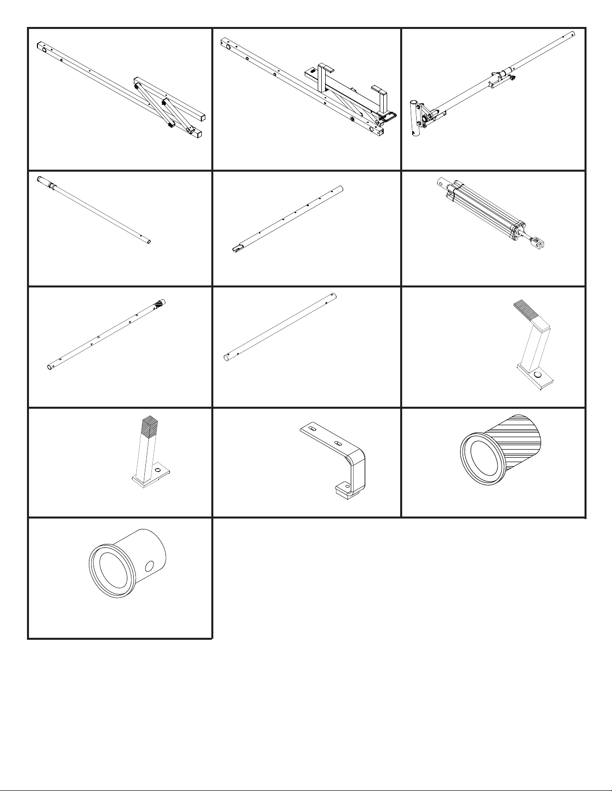
Front Cross-Member Assembly
Qty. 1
Rear Cross-Member Assembly
With Rear Slide Down
Qty. 1
Driveshaft/Handle Assembly
Qty. 1
Lower Handle Section
Qty. 1
Front Drive Tube
Qty. 1
Ladder Stop
Qty. 1
Upper Handle Section
Qty. 1
Center Drive Tube
Qty. 1
Mounting Brackets
Qty. 4
Cylinder
Qty. 1
Ladder Support
Qty. 1
Black Plastic Bushings
Qty. 2
White Plastic Bushings
Qty. 2
2
Page 3
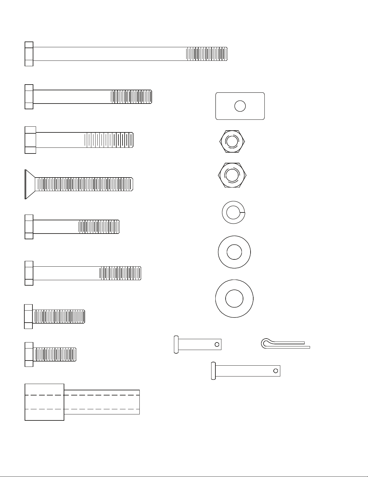
5/16-18 x 4-1/2" Hex Hd. Bolt
5/16-18 x 2-3/4" Hex Hd. Bolt
3/8-16 x 2-1/4" Hex Hd. Bolt
FASTENER CHART
Strip Nut
5/16-18 Nylon Lock Nut
5/16-18 x 2-1/4" Phillips Flat Hd. Screw
5/16-18 x 2" Hex Hd. Bolt
5/16-18 x 2-1/2" Hex Hd. Bolt
5/16-18 x 1-1/4" Hex Hd. Bolt
5/16-18 x 1" Hex Hd. Bolt
Clevis Pin (1")
3/8-16 Nylon Lock Nut
5/16" Lock Washer
5/16" Flat Washer
3/8" Flat Washer
Cotter Pin
Aluminum Bushing
Clevis Pin (1-1/2")
3
Page 4
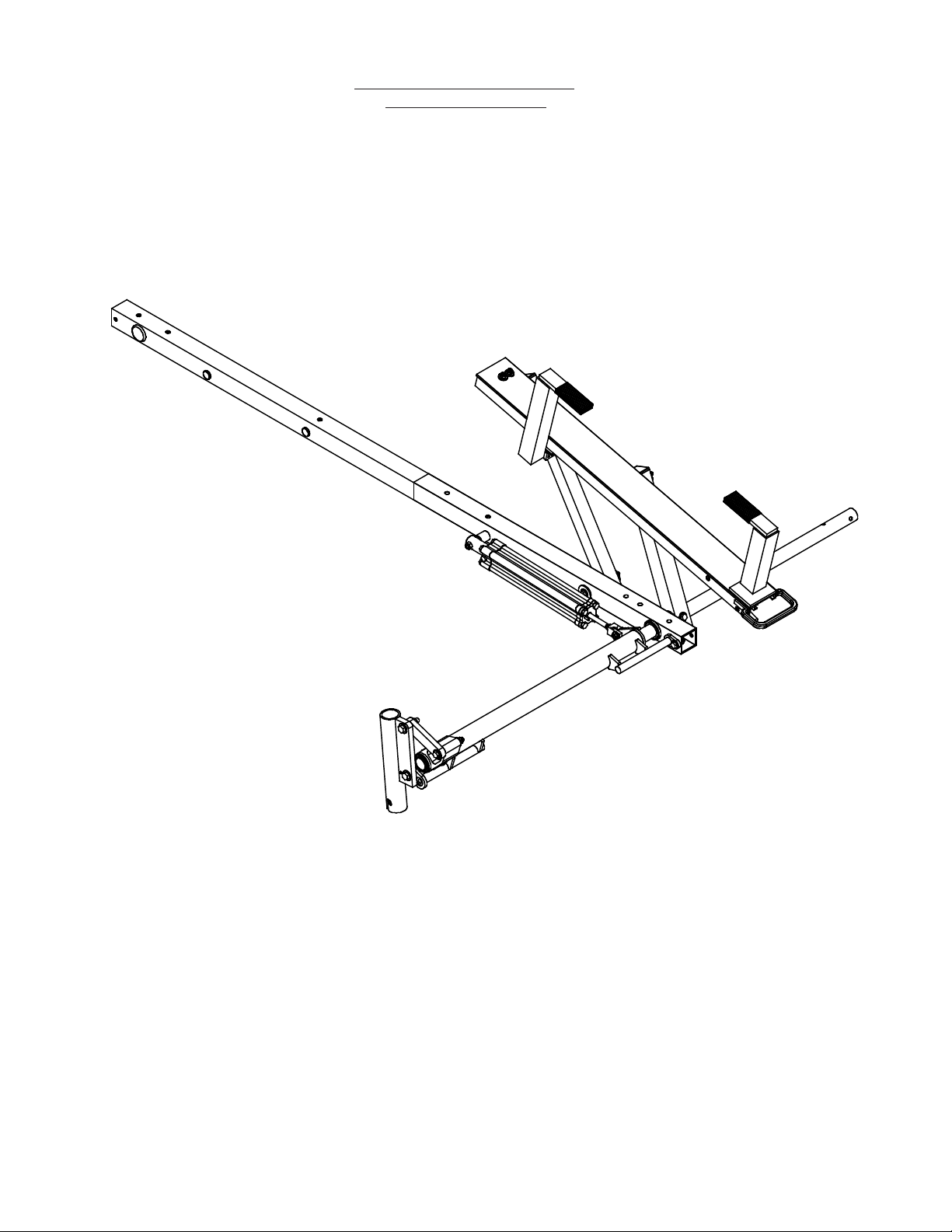
REAR ROTATION ASSEMBLY
With Rear Slide Down
4
Page 5
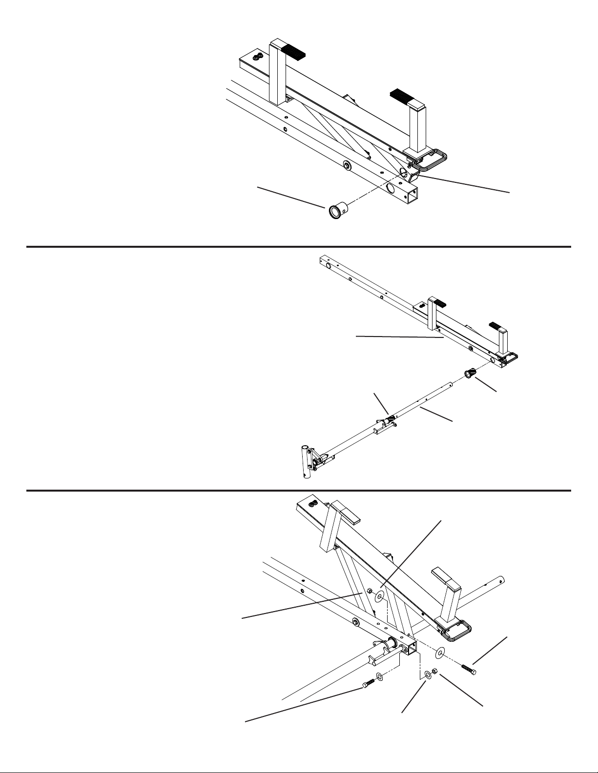
STEP 1
Slide a White Plastic Bushing (A)
into the Pivot Arm (B) as shown.
(A)
STEP 2
Use the supplied lubricant and coat the pre-assembled
Black Plastic Bushing (A). Insert the Driveshaft/Handle
Assembly (B) into the larger Black Plastic Bushing (C)
in the Rear Cross-Member Assembly (D) and through the
White Plastic Bushing in the Pivot Arm (Step 1) so that the
black bushings are fully seated.
(B)
(D)
(A)
(C)
(B)
STEP 3
Align holes in the Pivot Arm, White Plastic Bushing, and
Rear Drive Tube. Install the 3/8-16 x 2-1/4" Fastener. Next
install the 5/16-18 x 1" Fastener as shown.
3/8-16 Nylon
Lock Nut
NOTE: Tighten all marked (*)
fasteners to 200 in. lbs.
5/16-18 x 1"
Hex Hd. Bolt
(2) 3/8"
Flat Washer
* 3/8-16 x 2-1/4"
Hex Hd. Bolt
5/16-18 Nylon
5/16" Flat
Washer
Lock Nut
5
Page 6

STEP 4
Insert Aluminum Bushing (A) into Rear
Cross-Member (B). Attach back of Cylinder (C)
to cross member by installing 5/16-18 x 4-1/2"
Fastener. NOTE: After installing Bolt, apply
Loctite 290 to threads, then install the nut.
5/16-18 Nylon
Lock Nut
(B)
CYLINDER INSTALLATION
(3) 3/8" Flat
Washer
5/16-18 x 4-1/2"
Hex Hd. Bolt
STEP 5
Attach front of Cylinder as shown. Bend over
Cotter Pin after inserting it through Clevis Pin.
(A)
(C)
Cotter Pin
NOTE: Turn the Flow Control
counter clockwise to release
pressure. Adjust Flow Control Screw Per Instruction
Decal On Handle Tube after
final assembly and installation.
6
1" Clevis Pin
Page 7

FRONT ROTATION ASSEMBLY
7
Page 8

STEP 6
Slide a White Plastic Bushing (A)
into the Pivot Arm (B) as shown.
(B)
STEP 7
Use the supplied lubricant and coat the pre-assembled
Black Plastic Bushing (A). Insert the Front Drive Tube (B)
into the larger Black Plastic Bushing (C) in the Front CrossMember Assembly (D) and through the White Plastic Bushing in the Pivot Arm (Step 4) so that the black bushings are
fully seated.
(A)
(A)
(D)
STEP 8
Align holes in the Pivot Arm, White Plastic Bushing, and
Front Drive Tube. Install the 3/8-16 x 2-1/4" Fastener.
3/8-16 Nylon
Lock Nut
(C)
(B)
NOTE: Tighten all marked (*)
fasteners to 200 in. lbs.
(2) 3/8" Flat
Washer
* 3/8-16 x 2-1/4"
Hex Hd. Bolt
8
Page 9

STEP 9
Place the Ladder Support (A) on top of
the Connecting Tube (B) and install the
5/16-18 x 2-3/4" Fastener.
5/16-18 x 2-3/4"
Hex Hd. Bolt
(A)
5/16-18 Nylon
Lock Nut
(2) 5/16" Flat
Washer
(B)
STEP 10
Place the Ladder Stop (A) on top of the Cross-Member (B)
and install the 5/16-18 x 2-1/4" Fastener (Flat Hd. Screw).
5/16-18 x 2-1/4"
Flat Hd. Screw
5/16" Flat
Washer
5/16-18 Nylon
Lock Nut
(A)
(B)
9
Page 10

HOW TO DETERMINE RACK LENGTH FOR YOUR VAN
Rear Pivot Arm
FRONT TO REAR DRIVE TUBE ASSEMBLY
STEP 11
Determine desired front to rear length
from the chart shown above
(5' or 6' or 7' or 8') and install
5/16-18 x 2" Fasteners
(Tighten fasteners to 200 in. lbs.)
USE THESE HOLES FOR DESIRED
LENGTH
5'
6'
7'
8'
Front Pivot Arm
(4) 5/16-18
Nylon Lock
Nut
STEP 12
Cover any exposed holes on Front and Rear Drive Tubes with the 1" Dia. Vinyl Hole Covers
(8) 5/16" Flat
Washer
(4) 5/16-18 x 2"
Hex Hd. Bolt
STEP 13
Seal the ends of the Center Drive Tube, the four 5/16-18 Fasteners, and the two 3/8-16 Fasteners with the tube of sealant
supplied.
10
Page 11

STEP 14
Slide Lower Handle Section (A)
into Upper Handle Section (B) and
locate desired handle length. Align
holes and insert 1-1/2" Clevis Pin
(C).
HANDLE INSTALLATION PROCEDURE
(D)
(B)
(C)
(A)
11
Page 12

VEHICLE MOUNTING PROCEDURE
12
Page 13

STEP 15 (4 Places)
Attach the Mounting Bracket (A) to the CrossMember (B) (Drivers Side Shown) with the
5/16-18 Fasteners.
(B)
Note: Holes on top of Mounting
Brackets are OBROUND for adjustability when mounting Ladder
Rack Assembly to Sprinter. Hardware my have to be loosened to
position the Mounting Bracket directly over the roof channels. Retighten all hardware after Ladder
Rack Assembly is affixed to roof.
(4) 5/16-18
Flat Washer
(2) 5/16-18 x 2-1/2"
Hex Hd. Bolt
These two holes not used in
the High Roof Application
(2) 5/16-18
Nylon Lock Nut
STEP 16
WITH HELP! Place the ladder rack assembly on the vehicle on top of the factory installed roof channels. Insert Handle into
the Handle Receiver. Adjust placement of ladder rack assembly on the roof so the Handle clears the rear doors by 3”.
STEP 17
To attach the ladder rack assembly to the
Sprinter:
Insert two Strip Nuts into each of the factory installed roof channels from the rear
and place them directly below the four
mounting brackets. Fasten the Mounting
Bracket to the roof channel with the 5/1618 X 1-1/4” Hex Head Bolts, 5/16 Lock
Washers and 5/16 Flat Washers into the
Strip Nut in four places.
Important: Tighten all four 5/16-18
X 1-1/4” Hex Head Bolts to 150 inchpounds of torque.
(4) Strip Nut
(4) 5/16-18
Lock Washer
(4) 5/16-18
Flat Washer
(A)
(4) 5/16-18 x 1-1/4"
Hex Hd. Bolt
13
Page 14

DOWN
HANDLE ROTATION
UP
FINAL ASSEMBLY
LADDER & CYLINDER ADJUSTMENTS
STEP 18
Using the handle rotate rack to the
down position. Because the ladder
rack is not under the load of a ladder,
you may have to pull the front and rear
rotation assemblies down by hand after
moving the handle to the down position.
STEP 19
Actuating the release mechanism on
the rear slide down, lower the assembly. Place the ladder onto the ladder
rack and raise only the rear slide down
to the upper position. Do not rotate the
rack to the up position at this time.
Once the release lever is
pushed, you must support
the full weight of the ladder
RELEASE
CAUTION
and the ladder slide.
STEP 20
With the side of the ladder sitting on
the ladder support of the rear slide
down assembly in the up position,
adjust the ladder stop so that it is approximately 1/4" above the ladder and
tighten the fastener firmly.
LADDER STOP
RELEASE
LADDER SUPPORT
UP
REAR SLIDE DOWN
DOWN
STEP 21
Adjust the flow control screw on the
cylinder per the instruction decal on the
drive shaft handle tube until the ladder
operates smoothly as you rotate the
ladder up and down.
14
Page 15

Replacement Parts
ID# PART NUMBER DESCRIPTION USE WITH QTY
1 7325 Passenger Side Rear Slide Down 280,282 1
2 7360 Hydraulic Cylindge All Models Except 254 1
3 7363 Ladder Stop All Models Except 254 1
4 7364 Ladder Support All Models Except 254 1
5 7366 Bushing Kit All Models Except 254 1
6 7461 Passenger Side Drive Shaft for High Roof Vehicles 280,281,282,285 1
7 7489 Handle for High Roof Racks 280,281,282,283,284,285,286,287 1
8 70018 Mounting Brackets 280, 285 4
1
2
3
5
4
6
7
8
LIMITED WARRANTY
This LIMITED WARRANTY is made by Knaack LLC, 420 E. Terra Cotta Ave., Crystal Lake, Illinois to the original retail purchaser of KNAACK® or WEATHER
GUARD® products.
KNAACK LLC WARRANTS THAT KNAACK OR WEATHER GUARD PRODUCTS WILL BE FREE FROM DEFECTS IN MATERIAL AND WORKMANSHIP FOR A
PERIOD OF THREE (3) YEARS FROM DATE OF PURCHASE BY THE ORIGINAL RETAIL PURCHASER.
If, before the expiration of the Warranty period, purchaser discovers that the KNAACK or WEATHER GUARD product fails to fulfill the Warranty, purchaser shall contact
Knaack LLC to make arrangements for an inspection of the product. If Knaack LLC determines a defect exists, Knaack LLC shall, at its option and expense, repair or
replace any defective part. All Warranty repairs shall be made by an authorized KNAACK Product dealer or Knaack LLC approved service company.
This Warranty shall not apply if the KNAACK or WEATHER GUARD product has been subjected to misuse, abnormal service or handling, improper maintenance, or
alterations made by anyone other than a KNAACK or WEATHER GUARD Product dealer or a Knaack LLC approved service company.
THE WARRANTY PRINTED ABOVE IS THE ONLY WARRANTY APPLICABLE TO THIS PURCHASE. ALL OTHER WARRANTIES, EXPRESS OR IMPLIED, INCLUDING BUT NOT LIMITED TO THE IMPLIED WARRANTIES OF MERCHANTABILITY AND FITNESS FOR A PARTICULAR PURPOSE ARE HEREBY DISCLAIMED.
KNAACK LLC SHALL NOT BE LIABLE FOR ANY INCIDENTAL OR CONSEQUENTIAL DAMAGES ARISING OUT OF ANY BREACH OF THIS WARRANTY. NOR
SHALL THE DAMAGES EXCEED THE RETURN AMOUNT OF THE PURCHASE PRICE PAID BY THE ORIGINAL PURCHASER.
This Warranty is in lieu of all Warranties express or implied. The terms of this Warranty shall not be modified by any party, their successors or assigns. This Warranty
gives you specific legal rights, and you may also have other rights which vary from state to state.
Product fits based on vehicle design available at the revision date. Vehicle manufacturers may change specs after the revision date, so if
you have a vehicle produced with a model year date after the revision date, please contact your distributor or Knaack LLC to verify fitting
of product to vehicle.
If you have any questions, please call our customer service department at 1-800-456-7865. WEATHER GUARD Products are protected
by one or more of the following patents: U.S. 5145087, 5308126, 4509787, 4573731, 4618083, D-346355, D-346994, D-353574; Canada
1218968, 1224230, 1235100 and; U.K. 2233036. Other patents pending.
KNAACK
420 E. Terra Cotta Ave, Crystal Lake, IL 60014, 815-459-6020, info@knaack.com
©2002 Knaack LLC
Made In China
Refer to www.weatherguard.com for list of replacement parts for these racks.
15
LLC
Part No. 24-0265 REV. B ECN 5315 05/13
 Loading...